
Audi
Audi
Vorsprung durch Technik
Service Training
48
6
Audi A6 ’11
All rights reserved.
Technical specifi cations are subject to
change.
Copyright
AUDI AG
I/VK-35
AUDI AG
D-85045 Ingolstadt
Technical status 02/11
Printed in Germany
A11.5S00.80.20
Self Study Programme 486
2
Learning objectives of this Self Study Programme:
This Self Study Programme provides you with general information
about the Audi A6 ’11. Once you have worked your way through
this Self Study Programme, you will be ready to answer the follow-
ing questions:
• From which materials is the body assembled?
• Which engine-gearbox combinations are installed?
• How is 'seat occupied' indication implemented for the rear seat
row?
• Which type of steering is used on the Audi A6 ’11?
• Which sound systems are integrated?
• Which aspects of the air conditioning system have changed?
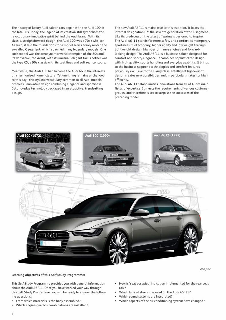
The history of luxury Audi saloon cars began with the Audi 100 in
the late 60s. Today, the legend of its creation still symbolises the
revolutionary innovative spirit behind the Audi brand. With its
classic, straightforward design, the Audi 100 was a 70s style icon.
As such, it laid the foundations for a model series fi rmly rooted the
so-called C segment, which spawned many legendary models. One
such model was the aerodynamic world champion of the 80s and
its derivative, the Avant, with its unusual, elegant tail. Another was
the type C5, a 90s classic with its taut lines and soft rear contours.
Meanwhile, the Audi 100 had become the Audi A6 in the interests
of a harmonised nomenclature. Yet one thing remains unchanged
to this day - the stylistic vocabulary common to all Audi models:
timeless, innovative design combining elegance and sportiness.
Cutting-edge technology packaged in an attractive, trendsetting
design.
The new Audi A6 ’11 remains true to this tradition. It bears the
internal designation C7: the seventh generation of the C segment.
Like its predecessor, the latest off spring is designed to inspire.
The Audi A6 ’11 stands for more safety and comfort, contemporary
sportiness, fuel economy, higher agility and low weight through
lightweight design, high-performance engines and forward-
looking design. The Audi A6 ’11 is a business saloon designed for
comfort and sporty elegance. It combines sophisticated design
with high quality, sporty handling and everyday usability. It brings
to the business segment technologies and comfort features
previously exclusive to the luxury class. Intelligent lightweight
design creates new possibilities and, in particular, makes for high
effi ciency.
The Audi A6 ’11 saloon unifi es innovations from all of Audi's main
fi elds of expertise. It meets the requirements of various customer
groups, and therefore is set to surpass the successes of the
preceding model.
486_064
3
!
IntroductionIn brief _______________________________________________________________________________________________________________________________________________________ 4
BodyOverview _____________________________________________________________________________________________________________________________________________________ 6
Occupant protectionIntroduction _________________________________________________________________________________________________________________________________________________ 8
Components _________________________________________________________________________________________________________________________________________________ 9
EnginesPetrol engines ______________________________________________________________________________________________________________________________________________12
Diesel engines ______________________________________________________________________________________________________________________________________________16
Engine/gearbox combinations ____________________________________________________________________________________________________________________________25
Power transmissionOverview ____________________________________________________________________________________________________________________________________________________26
ATF heating/cooling _______________________________________________________________________________________________________________________________________28
ATF cooling _________________________________________________________________________________________________________________________________________________30
Gear recognition sensor G604 ____________________________________________________________________________________________________________________________32
ChassisIntroduction ________________________________________________________________________________________________________________________________________________34
Axles _________________________________________________________________________________________________________________________________________________________35
adaptive air suspension (aas) _____________________________________________________________________________________________________________________________36
Steering system ____________________________________________________________________________________________________________________________________________37
Brake system _______________________________________________________________________________________________________________________________________________38
Wheels and tyres ___________________________________________________________________________________________________________________________________________41
adaptive cruise control (ACC) _____________________________________________________________________________________________________________________________41
Electrical systemAudi drive select ____________________________________________________________________________________________________________________________________________42
Vehicle electrical system __________________________________________________________________________________________________________________________________45
Topology ____________________________________________________________________________________________________________________________________________________46
Exterior lighting ____________________________________________________________________________________________________________________________________________48
Headlight ___________________________________________________________________________________________________________________________________________________50
Tail lights ____________________________________________________________________________________________________________________________________________________63
Air conditioningVersions of the air conditioning system _________________________________________________________________________________________________________________66
effi ciency mode _____________________________________________________________________________________________________________________________________________68
Air improvement system __________________________________________________________________________________________________________________________________69
InfotainmentOverview of versions _______________________________________________________________________________________________________________________________________70
Sound systems _____________________________________________________________________________________________________________________________________________72
Aerial systems ______________________________________________________________________________________________________________________________________________73
ServiceInspection and maintenance ______________________________________________________________________________________________________________________________74
AnnexSelf Study Programmes ___________________________________________________________________________________________________________________________________75
The Self Study Programme teaches a basic knowledge of the design and functions of new models, new auto-
motive components or new technologies.
It is not a Repair Manual! Figures are given for explanatory purposes only and refer to the data valid at the
time of preparation of the SSP.
For maintenance and repair work, always refer to the current technical literature.
Note
Reference
Contents
4
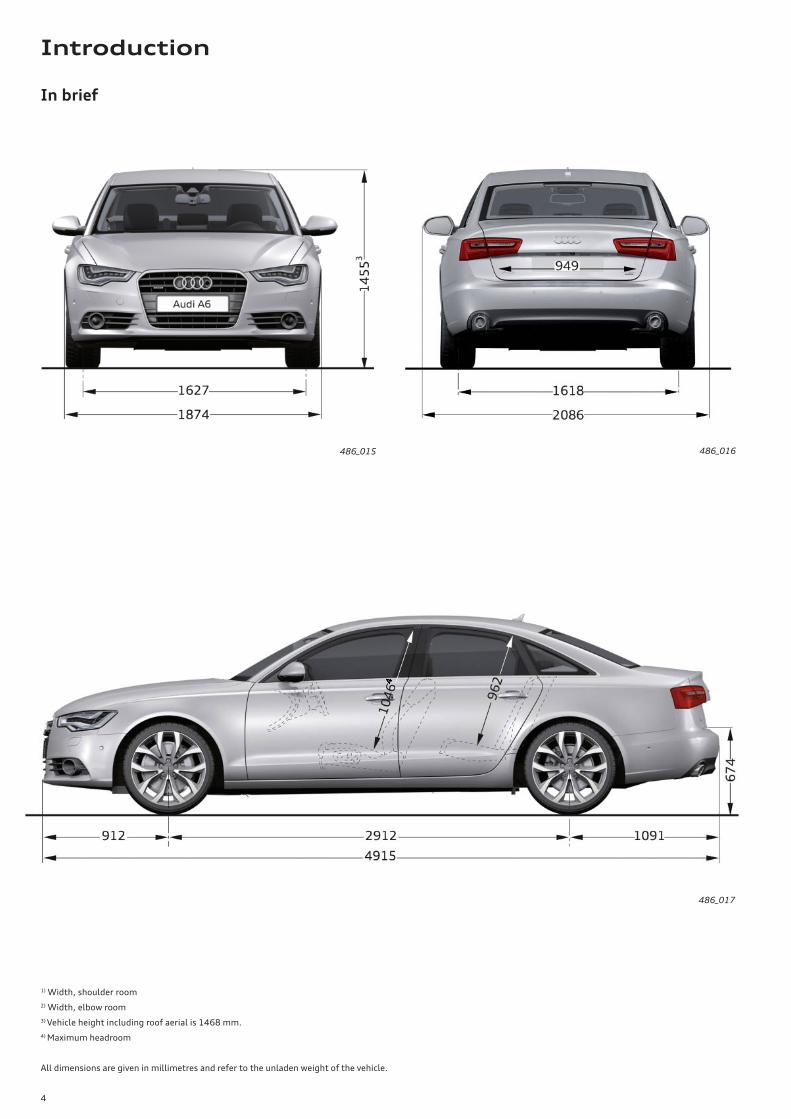
In brief
486_015
486_017
486_016
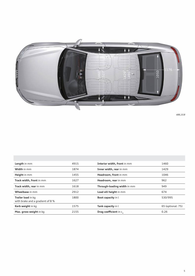
1) Width, shoulder room
2) Width, elbow room
3) Vehicle height including roof aerial is 1468 mm.
4) Maximum headroom
All dimensions are given in millimetres and refer to the unladen weight of the vehicle.
Introduction
5
Length in mm 4915 Interior width, front in mm 1460
Width in mm 1874 Inner width, rear in mm 1429
Height in mm 1455 Headroom, front in mm 1046
Track width, front in mm 1627 Headroom, rear in mm 962
Track width, rear in mm 1618 Through-loading width in mm 949
Wheelbase in mm 2912 Load sill height in mm 674
Trailer load in kg
with brake and a gradient of 8 %
1800 Boot capacity in l 530/995
Kerb weight in kg 1575 Tank capacity in l 65 (optional: 75)
Max. gross weight in kg 2155 Drag coeffi cient in cw
0.26
486_018
6
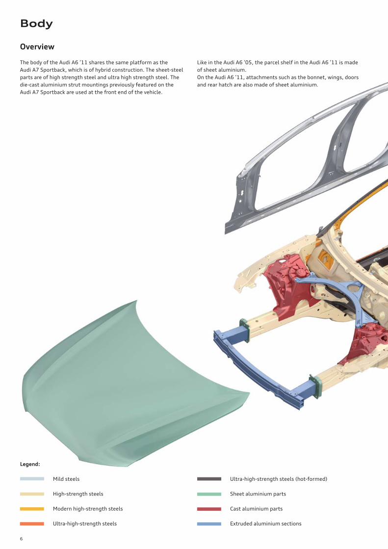
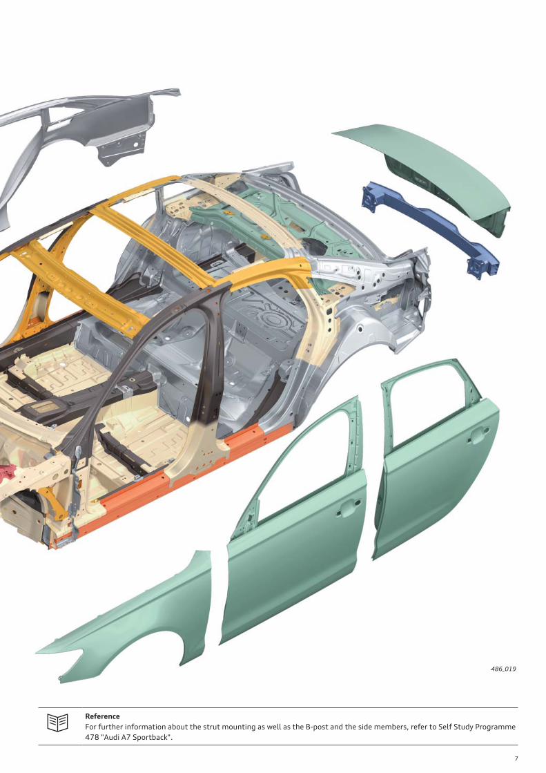
Overview
The body of the Audi A6 ’11 shares the same platform as the
Audi A7 Sportback, which is of hybrid construction. The sheet-steel
parts are of high strength steel and ultra high strength steel. The
die-cast aluminium strut mountings previously featured on the
Audi A7 Sportback are used at the front end of the vehicle.
Like in the Audi A6 ’05, the parcel shelf in the Audi A6 ’11 is made
of sheet aluminium.
On the Audi A6 ’11, attachments such as the bonnet, wings, doors
and rear hatch are also made of sheet aluminium.
Legend:
Mild steels
High-strength steels
Modern high-strength steels
Ultra-high-strength steels
Ultra-high-strength steels (hot-formed)
Sheet aluminium parts
Cast aluminium parts
Extruded aluminium sections
Body
7
486_019
Reference
For further information about the strut mounting as well as the B-post and the side members, refer to Self Study Programme
478 "Audi A7 Sportback".
8
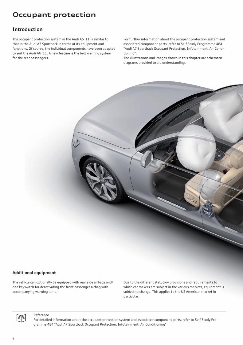
Introduction
The occupant protection system in the Audi A6 ’11 is similar to
that in the Audi A7 Sportback in terms of its equipment and
functions. Of course, the individual components have been adapted
to suit the Audi A6 ’11. A new feature is the belt warning system
for the rear passengers.
For further information about the occupant protection system and
associated component parts, refer to Self Study Programme 484
"Audi A7 Sportback Occupant Protection, Infotainment, Air Condi-
tioning".
The illustrations and images shown in this chapter are schematic
diagrams provided to aid understanding.
Additional equipment
The vehicle can optionally be equipped with rear side airbags and/
or a keyswitch for deactivating the front passenger airbag with
accompanying warning lamp.
Due to the diff erent statutory provisions and requirements to
which car makers are subject in the various markets, equipment is
subject to change. This applies to the US American market in
particular.
Reference
For detailed information about the occupant protection system and associated component parts, refer to Self Study Pro-
gramme 484 "Audi A7 Sportback Occupant Protection, Infotainment, Air Conditioning".
Occupant protection
9
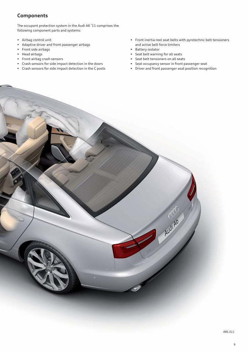
Components
The occupant protection system in the Audi A6 ’11 comprises the
following component parts and systems:
• Airbag control unit
• Adaptive driver and front passenger airbags
• Front side airbags
• Head airbags
• Front airbag crash sensors
• Crash sensors for side impact detection in the doors
• Crash sensors for side impact detection in the C posts
• Front inertia-reel seat belts with pyrotechnic belt tensioners
and active belt force limiters
• Battery isolator
• Seat belt warning for all seats
• Seat belt tensioners on all seats
• Seat occupancy sensor in front passenger seat
• Driver and front passenger seat position recognition
486_011

10
Legend of fi gure on page 11:
E24 Seat belt switch, driver side
E25 Seat belt switch, front passenger side
E224 Airbag disabling switch, passenger side (optional)
E258 Rear belt switch, driver side
E259 Rear belt switch, front passenger side
E609 Seat occupied sensor, front passenger side
G128 Seat occupancy sensor, front passenger side
G179 Side airbag crash sensor, driver side (driver door)
G180 Side airbag crash sensor, front passenger side (front pas-
senger door)
G256 Rear side airbag crash sensor, driver side (C post)
G257 Rear side airbag crash sensor, driver side (C post)
G283 Front airbag crash sensor, driver side (left front end)
G284 Front airbag crash sensor, front passenger side
(right front end)
G551 Belt force limiter, driver side
G552 Belt force limiter, front passenger side
G553 Seat position sensor, driver side
G554 Seat position sensor, front passenger side
Rear seat belt reminder
Rear seat belt reminder
After turning on the ignition, the status of the seat belts (fas-
tened/not fastened) is indicated on the centre display of the dash
panel insert for 31 seconds.
Every change in status is indicated for a further 31 seconds. If a
rear passenger removes his/her seat belt while the vehicle is travel-
ling at a speed of greater than 25 kph, an acoustic warning sounds
once and the relevant indicator on the centre display begins fl ash-
ing for 31 seconds.
The airbag control unit J234 receives information on whether the
seat belts are fastened from the rear belt switches, driver side
E258, front passenger side E259 and centre E609.
486_012
486_013
on
not
worn
active
active
off
worn
lights up
31 sec.
fl ashes
31 sec.
lights up
31 sec.off
off
> 25 kph
< 25 kph
Seat belt
Terminal 15
Visual
display
Seat belt not
fastened
Seat belt
fastened
Acoustic
warning
Speed
J234 Airbag control unit
J285 Control unit in dash panel insert
J533 Data bus diagnostic interface (gateway)
K19 Seat belt reminder warning lamp
K75 Passenger airbag off
K145 Passenger airbag off warning lamp
(PASSENGER AIRBAG OFF) (optional)
N95 Driver side airbag igniter
N131 Front passenger side airbag igniter 1
N153 Driver side seat belt pretensioner 1
N154 Front passenger side belt pretensioner 1
N199 Side airbag igniter, driver side
N200 Side airbag igniter, front passenger side
N251 Head airbag igniter, driver side
N252 Head airbag igniter, front passenger side
N253 Battery isolation igniter
N490 Driver airbag relief valve igniter
N491 Front passenger airbag relief valve igniter
T16 16 pin connector, diagnostic port
11
486_014
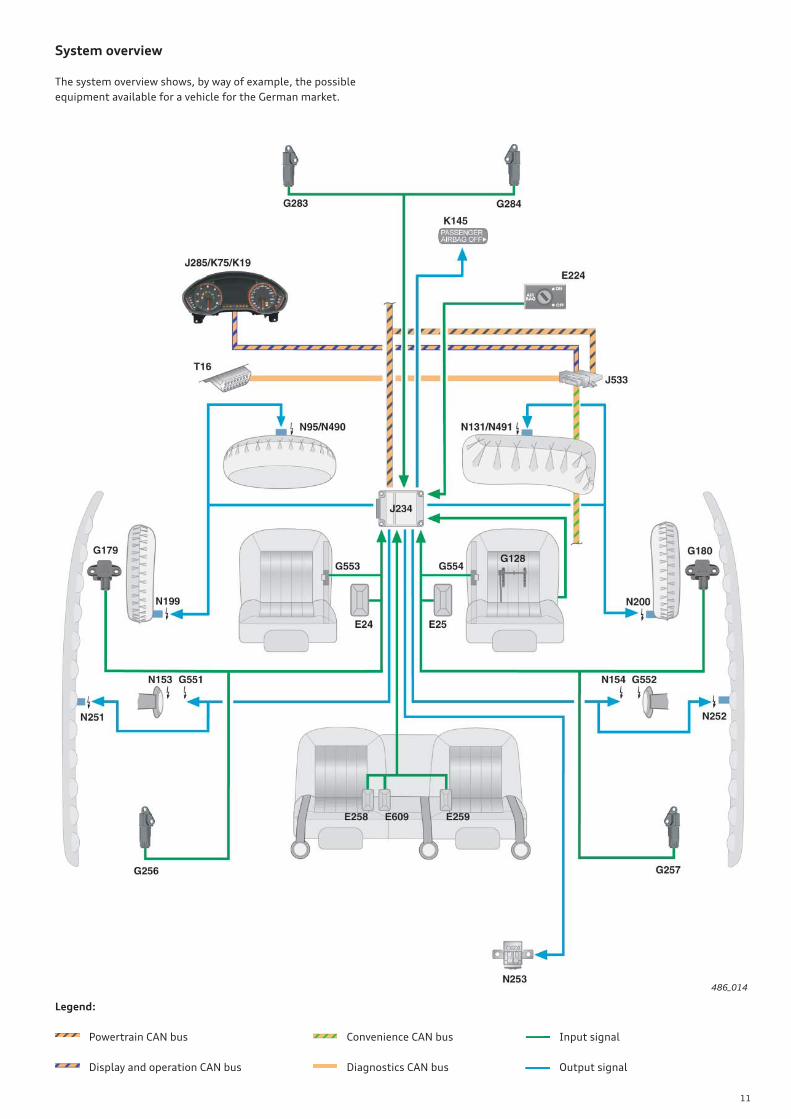
System overview
The system overview shows, by way of example, the possible
equipment available for a vehicle for the German market.
Legend:
Powertrain CAN bus
Display and operation CAN bus
Input signal
Output signal
Convenience CAN bus
Diagnostics CAN bus
12
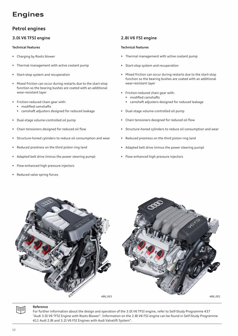
3.0l V6 TFSI engine
Technical features
• Charging by Roots blower
• Thermal management with active coolant pump
• Start-stop system and recuperation
• Mixed friction can occur during restarts due to the start-stop
function so the bearing bushes are coated with an additional
wear-resistant layer
• Friction-reduced chain gear with:
• modifi ed camshafts
• camshaft adjusters designed for reduced leakage
• Dual-stage volume-controlled oil pump
• Chain tensioners designed for reduced oil fl ow
• Structure-honed cylinders to reduce oil consumption and wear
• Reduced prestress on the third piston ring land
• Adapted belt drive (minus the power steering pump)
• Flow-enhanced high pressure injectors
• Reduced valve spring forces
Reference
For further information about the design and operation of the 3.0l V6 TFSI engine, refer to Self-Study Programme 437
"Audi 3.0l V6 TFSI Engine with Roots Blower". Information on the 2.8l V6 FSI engine can be found in Self-Study Programme
411 Audi 2.8l and 3.2l V6 FSI Engines with Audi Valvelift System".
486_001
2.8l V6 FSI engine
Technical features
• Thermal management with active coolant pump
• Start-stop system and recuperation
• Mixed friction can occur during restarts due to the start-stop
function so the bearing bushes are coated with an additional
wear-resistant layer
• Friction-reduced chain gear with:
• modifi ed camshafts
• camshaft adjusters designed for reduced leakage
• Dual-stage volume-controlled oil pump
• Chain tensioners designed for reduced oil fl ow
• Structure-honed cylinders to reduce oil consumption and wear
• Reduced prestress on the third piston ring land
• Adapted belt drive (minus the power steering pump)
• Flow-enhanced high pressure injectors
486_003
Petrol engines
Engines
13
486_134486_002
Engine speed [rpm]Engine speed [rpm]
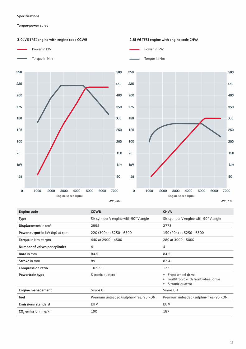
Engine code CGWB CHVA
Type Six cylinder V engine with 90° V angle Six cylinder V engine with 90° V angle
Displacement in cm3 2995 2773
Power output in kW (hp) at rpm 220 (300) at 5250 – 6500 150 (204) at 5250 – 6500
Torque in Nm at rpm 440 at 2900 – 4500 280 at 3000 – 5000
Number of valves per cylinder 4 4
Bore in mm 84.5 84.5
Stroke in mm 89 82.4
Compression ratio 10.5 : 1 12 : 1
Powertrain type S tronic quattro • Front wheel drive
• multitronic with front wheel drive
• S tronic quattro
Engine management Simos 8 Simos 8.1
fuel Premium unleaded (sulphur-free) 95 RON Premium unleaded (sulphur-free) 95 RON
Emissions standard EU V EU V
CO2 emission in g/km 190 187
Specifi cations
Torque-power curve
3.0l V6 TFSI engine with engine code CGWB
Power in kW
Torque in Nm
2.8l V6 TFSI engine with engine code CHVA
Power in kW
Torque in Nm
14
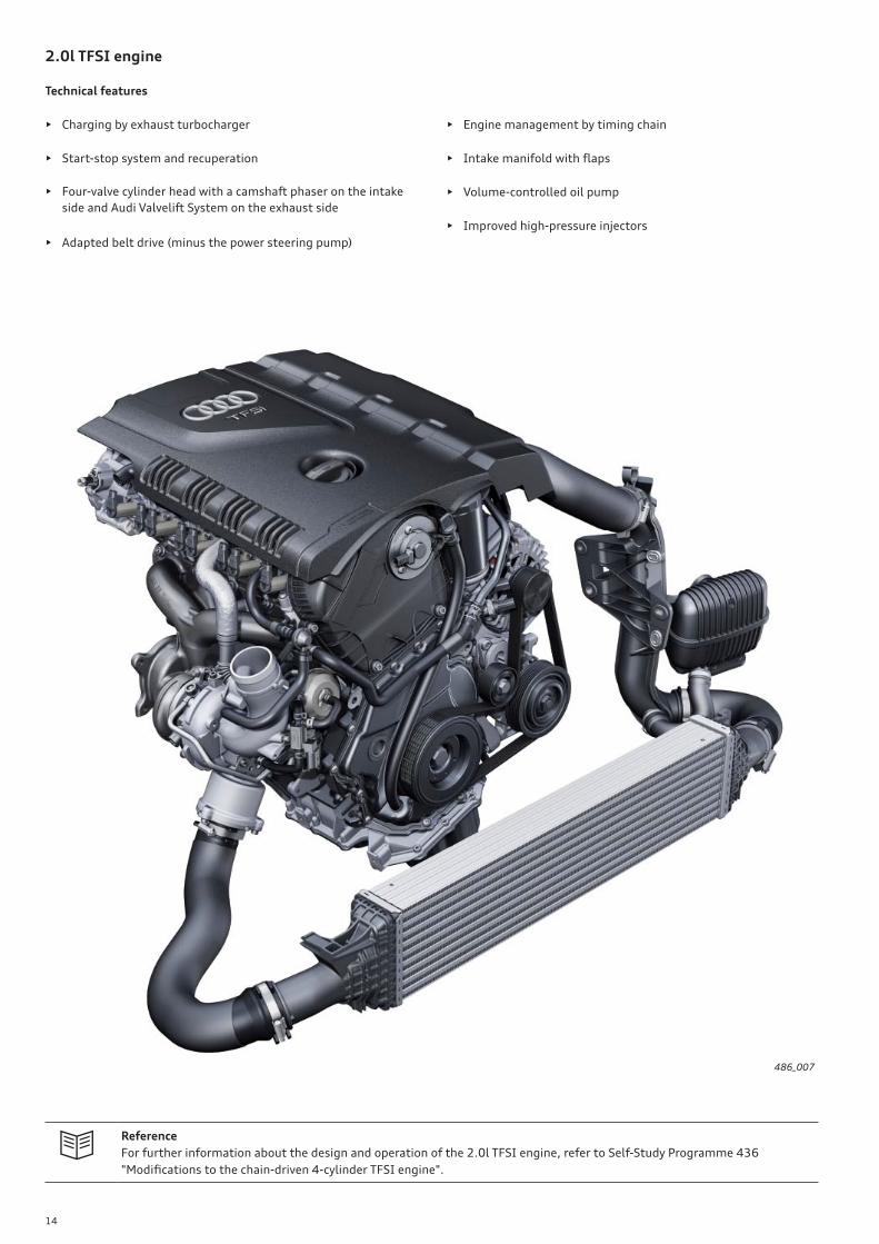
2.0l TFSI engine
Technical features
• Charging by exhaust turbocharger
• Start-stop system and recuperation
• Four-valve cylinder head with a camshaft phaser on the intake
side and Audi Valvelift System on the exhaust side
• Adapted belt drive (minus the power steering pump)
Reference
For further information about the design and operation of the 2.0l TFSI engine, refer to Self-Study Programme 436
"Modifi cations to the chain-driven 4-cylinder TFSI engine".
486_007
• Engine management by timing chain
• Intake manifold with fl aps
• Volume-controlled oil pump
• Improved high-pressure injectors
15
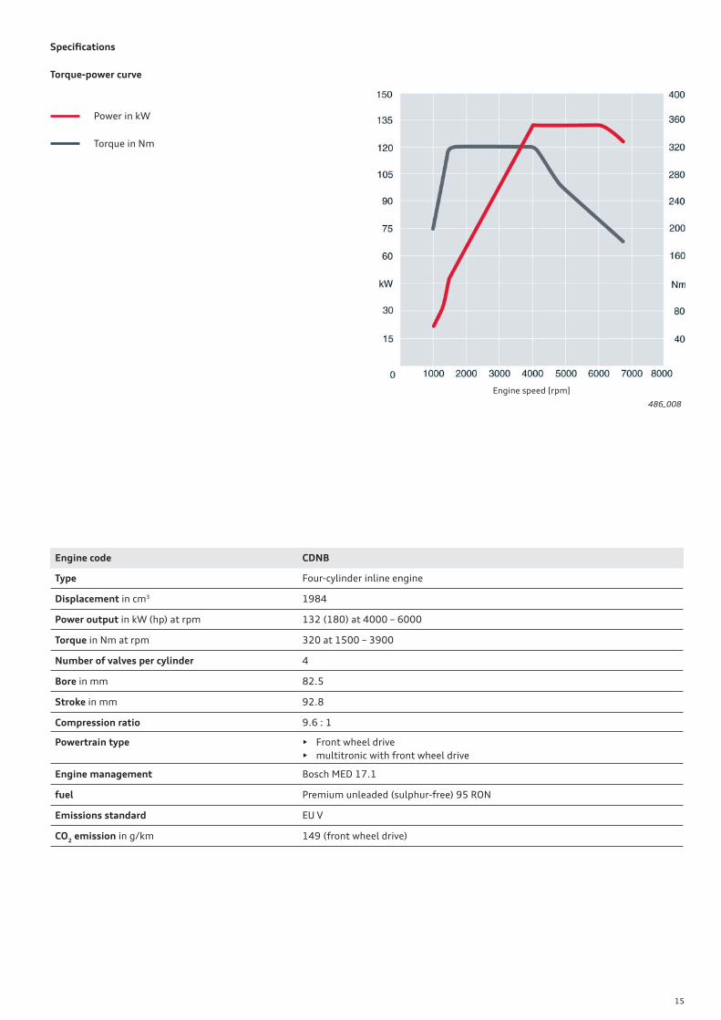
486_008
Specifi cations
Torque-power curve
Power in kW
Torque in Nm
Engine speed [rpm]
Engine code CDNB
Type Four-cylinder inline engine
Displacement in cm3 1984
Power output in kW (hp) at rpm 132 (180) at 4000 – 6000
Torque in Nm at rpm 320 at 1500 – 3900
Number of valves per cylinder 4
Bore in mm 82.5
Stroke in mm 92.8
Compression ratio 9.6 : 1
Powertrain type • Front wheel drive
• multitronic with front wheel drive
Engine management Bosch MED 17.1
fuel Premium unleaded (sulphur-free) 95 RON
Emissions standard EU V
CO2 emission in g/km 149 (front wheel drive)
16
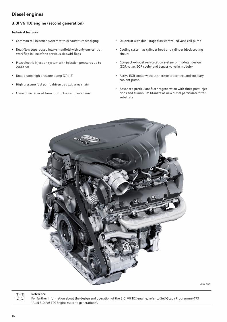
Reference
For further information about the design and operation of the 3.0l V6 TDI engine, refer to Self-Study Programme 479
"Audi 3.0l V6 TDI Engine (second generation)".
Diesel engines
3.0l V6 TDI engine (second generation)
Technical features
• Common rail injection system with exhaust turbocharging
• Dual-fl ow superposed intake manifold with only one central
swirl fl ap in lieu of the previous six swirl fl aps
• Piezoelectric injection system with injection pressures up to
2000 bar
• Dual-piston high pressure pump (CP4.2)
• High pressure fuel pump driven by auxiliaries chain
• Chain drive reduced from four to two simplex chains
486_005
• Oil circuit with dual-stage fl ow controlled vane cell pump
• Cooling system as cylinder head and cylinder block cooling
circuit
• Compact exhaust recirculation system of modular design
(EGR valve, EGR cooler and bypass valve in module)
• Active EGR cooler without thermostat control and auxiliary
coolant pump
• Advanced particulate fi lter regeneration with three post-injec-
tions and aluminium titanate as new diesel particulate fi lter
substrate

17
Specifi cations
Torque-power curve
Engine with code CDUC
Power in kW
Torque in Nm
Engine speed [rpm]
486_075
Engine code CDUC CLAB, CLAA
Type Six cylinder V engine with 90° V angle Six cylinder V engine with 90° V angle
Displacement in cm3 2967 2967
Power output in kW (hp) at rpm 180 (245) at 4000 – 4500 150 (204) at 3750 – 4500 (front wheel drive)
150 (204) at 3250 – 4500 (quattro)
Torque in Nm at rpm 500 at 1400 – 3250 400 at 1250 – 3500 (front wheel drive)
450 at 1250 – 3000 (quattro)
Number of valves per cylinder 4 4
Bore in mm 83 83
Stroke in mm 91.4 91.4
Compression ratio 16.8 : 1 16.8 : 1
Powertrain type S tronic quattro • Front wheel drive
• multitronic with front wheel drive
• S tronic quattro
Engine management Bosch EDC 17 Bosch EDC 17
fuel Diesel to EN 590 Diesel to EN 590
Maximum injection pressure in bar 1800 2000
Emissions standard EU V EU V
CO2 emission in g/km 158 137 (front wheel drive)
149 (quattro)
Engine with code CLAB
Power in kW
Torque in Nm
Engine with code CLAA
Power in kW
Torque in Nm
Engine speed [rpm]
486_006
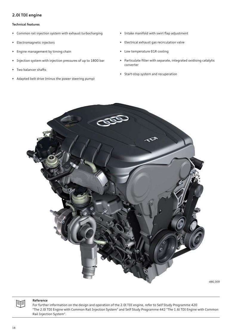
18
2.0l TDI engine
Technical features
• Common rail injection system with exhaust turbocharging
• Electromagnetic injectors
• Engine management by timing chain
• Injection system with injection pressures of up to 1800 bar
• Two balancer shafts
• Adapted belt drive (minus the power steering pump)
• Intake manifold with swirl fl ap adjustment
• Electrical exhaust gas recirculation valve
• Low temperature EGR cooling
• Particulate fi lter with separate, integrated oxidising catalytic
converter
• Start-stop system and recuperation
Reference
For further information on the design and operation of the 2.0l TDI engine, refer to Self Study Programme 420
"The 2.0l TDI Engine with Common Rail Injection System" and Self Study Programme 442 "The 1.6l TDI Engine with Common
Rail Injection System".
486_009
19
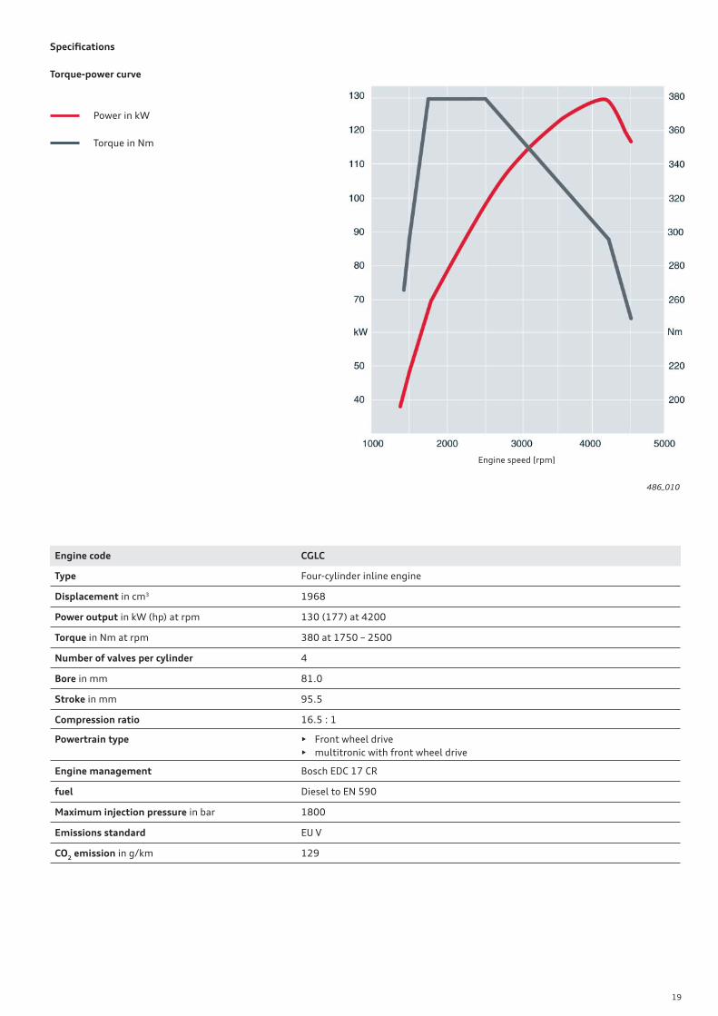
Specifi cations
Torque-power curve
Power in kW
Torque in Nm
Engine speed [rpm]
486_010
Engine code CGLC
Type Four-cylinder inline engine
Displacement in cm3 1968
Power output in kW (hp) at rpm 130 (177) at 4200
Torque in Nm at rpm 380 at 1750 – 2500
Number of valves per cylinder 4
Bore in mm 81.0
Stroke in mm 95.5
Compression ratio 16.5 : 1
Powertrain type • Front wheel drive
• multitronic with front wheel drive
Engine management Bosch EDC 17 CR
fuel Diesel to EN 590
Maximum injection pressure in bar 1800
Emissions standard EU V
CO2 emission in g/km 129

20
Fuel system on the 2.0l TDI engine
Fuel metering valve
N290
High pressure pump
CP4.1
Fuel temperature sender
G81Non-return valve
(throttle device)
Fuel fi lter
Fuel pressure sensor
G247
to e
ng
ine
co
ntr
ol
un
it J
62
3
Ba
tte
ry (
po
siti
ve)
Fuel high pressure 230 — 1800 bar
Fuel supply pressure approx. 5 bar
Fuel return pressure from the
injectors approx. 2 bar
Colour key:
approx. 5 bar
approx. 2 bar
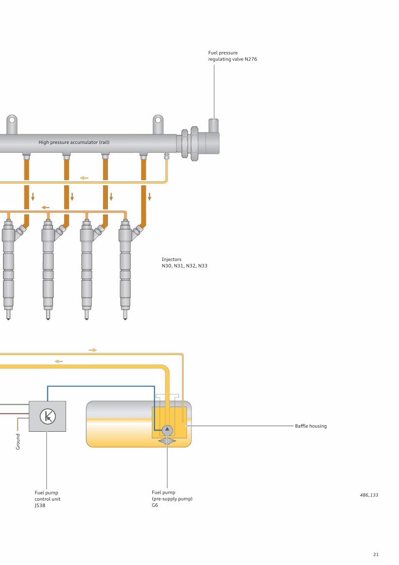
21
486_133
High pressure accumulator (rail)
Fuel pressure
regulating valve N276
Injectors
N30, N31, N32, N33
Baffl e housing
Fuel pump
(pre-supply pump)
G6
Fuel pump
control unit
J538
Gro
un
d
22
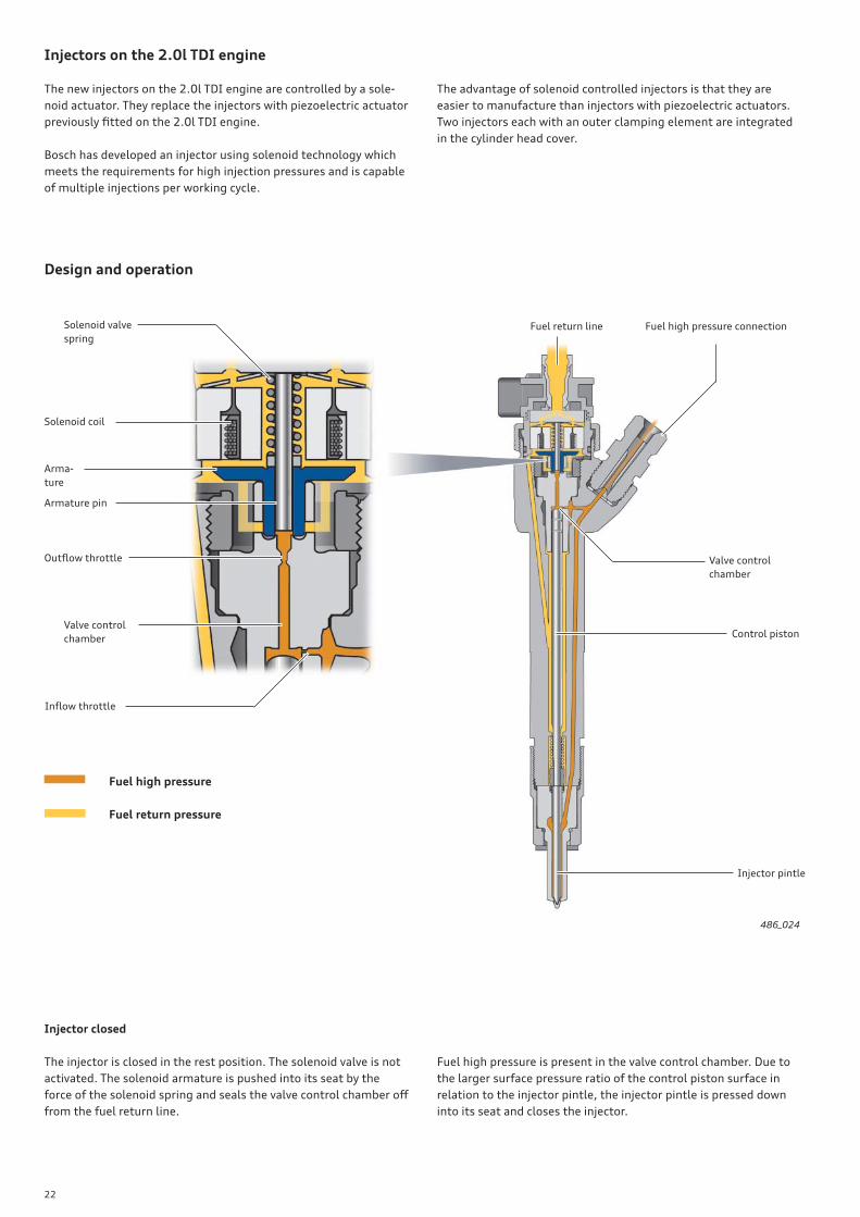
Injectors on the 2.0l TDI engine
The new injectors on the 2.0l TDI engine are controlled by a sole-
noid actuator. They replace the injectors with piezoelectric actuator
previously fi tted on the 2.0l TDI engine.
Bosch has developed an injector using solenoid technology which
meets the requirements for high injection pressures and is capable
of multiple injections per working cycle.
The advantage of solenoid controlled injectors is that they are
easier to manufacture than injectors with piezoelectric actuators.
Two injectors each with an outer clamping element are integrated
in the cylinder head cover.
Design and operation
486_024
Arma-
ture
Solenoid coil
Solenoid valve
spring
Armature pin
Outfl ow throttle
Valve control
chamber
Infl ow throttle
Fuel return line Fuel high pressure connection
Valve control
chamber
Control piston
Injector pintle
Fuel high pressure
Fuel return pressure
Injector closed
The injector is closed in the rest position. The solenoid valve is not
activated. The solenoid armature is pushed into its seat by the
force of the solenoid spring and seals the valve control chamber off
from the fuel return line.
Fuel high pressure is present in the valve control chamber. Due to
the larger surface pressure ratio of the control piston surface in
relation to the injector pintle, the injector pintle is pressed down
into its seat and closes the injector.
23
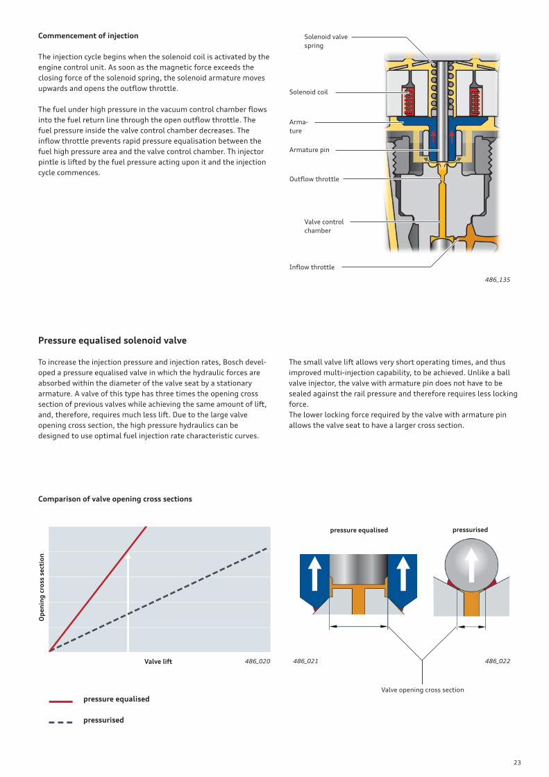
Commencement of injection
The injection cycle begins when the solenoid coil is activated by the
engine control unit. As soon as the magnetic force exceeds the
closing force of the solenoid spring, the solenoid armature moves
upwards and opens the outfl ow throttle.
The fuel under high pressure in the vacuum control chamber fl ows
into the fuel return line through the open outfl ow throttle. The
fuel pressure inside the valve control chamber decreases. The
infl ow throttle prevents rapid pressure equalisation between the
fuel high pressure area and the valve control chamber. Th injector
pintle is lifted by the fuel pressure acting upon it and the injection
cycle commences.
Pressure equalised solenoid valve
To increase the injection pressure and injection rates, Bosch devel-
oped a pressure equalised valve in which the hydraulic forces are
absorbed within the diameter of the valve seat by a stationary
armature. A valve of this type has three times the opening cross
section of previous valves while achieving the same amount of lift,
and, therefore, requires much less lift. Due to the large valve
opening cross section, the high pressure hydraulics can be
designed to use optimal fuel injection rate characteristic curves.
The small valve lift allows very short operating times, and thus
improved multi-injection capability, to be achieved. Unlike a ball
valve injector, the valve with armature pin does not have to be
sealed against the rail pressure and therefore requires less locking
force.
The lower locking force required by the valve with armature pin
allows the valve seat to have a larger cross section.
Comparison of valve opening cross sections
Op
en
ing
cro
ss s
ect
ion
Valve lift
pressure equalised
pressurised
486_020
pressurisedpressure equalised
Valve opening cross section
486_021 486_022
486_135
Arma-
ture
Solenoid coil
Solenoid valve
spring
Armature pin
Outfl ow throttle
Valve control
chamber
Infl ow throttle
24
!
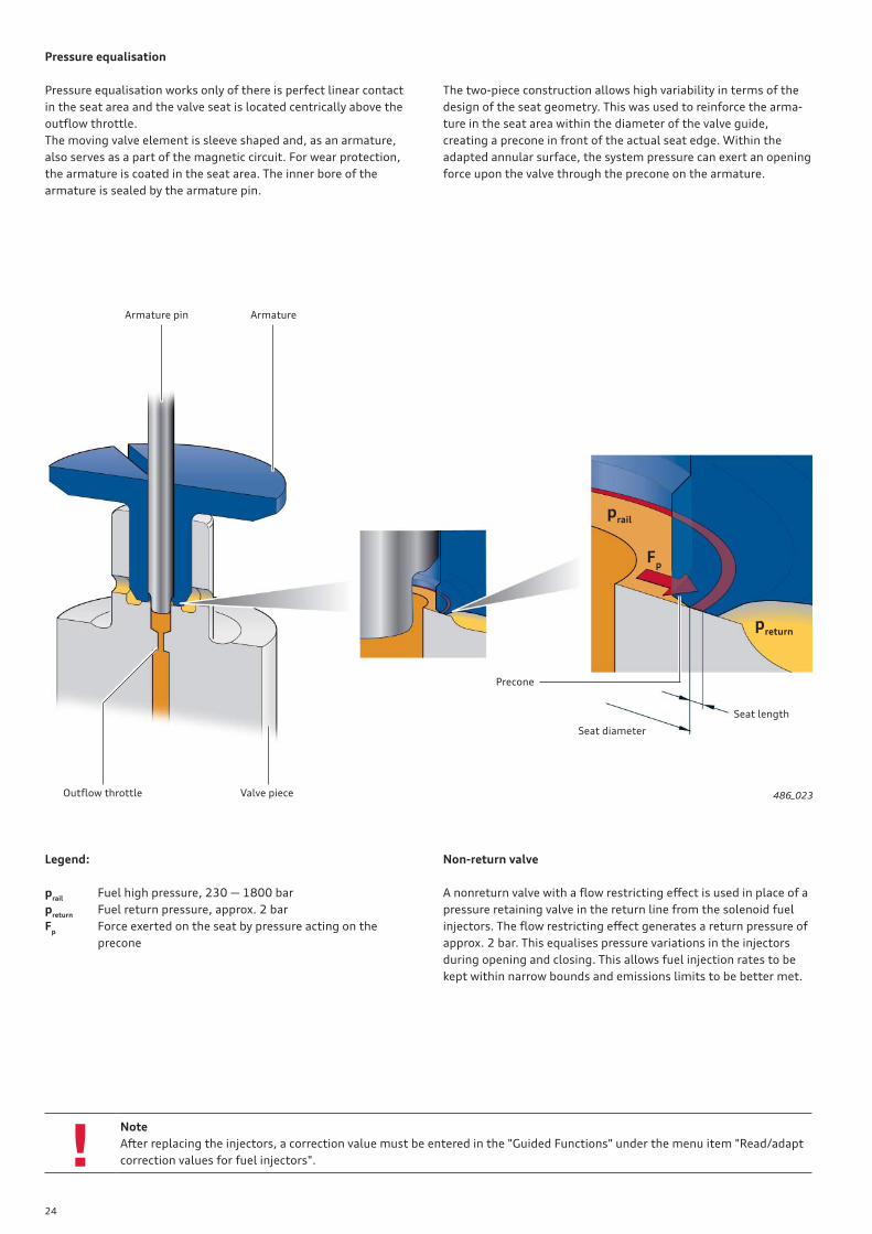
Pressure equalisation
Armature pin Armature
Outfl ow throttle Valve piece
Seat length
Seat diameter
Precone
486_023
Pressure equalisation works only of there is perfect linear contact
in the seat area and the valve seat is located centrically above the
outfl ow throttle.
The moving valve element is sleeve shaped and, as an armature,
also serves as a part of the magnetic circuit. For wear protection,
the armature is coated in the seat area. The inner bore of the
armature is sealed by the armature pin.
The two-piece construction allows high variability in terms of the
design of the seat geometry. This was used to reinforce the arma-
ture in the seat area within the diameter of the valve guide,
creating a precone in front of the actual seat edge. Within the
adapted annular surface, the system pressure can exert an opening
force upon the valve through the precone on the armature.
prail
preturn
Fp
Legend:
prail
Fuel high pressure, 230 — 1800 bar
preturn
Fuel return pressure, approx. 2 bar
Fp Force exerted on the seat by pressure acting on the
precone
Non-return valve
A nonreturn valve with a fl ow restricting eff ect is used in place of a
pressure retaining valve in the return line from the solenoid fuel
injectors. The fl ow restricting eff ect generates a return pressure of
approx. 2 bar. This equalises pressure variations in the injectors
during opening and closing. This allows fuel injection rates to be
kept within narrow bounds and emissions limits to be better met.
Note
After replacing the injectors, a correction value must be entered in the "Guided Functions" under the menu item "Read/adapt
correction values for fuel injectors".
25
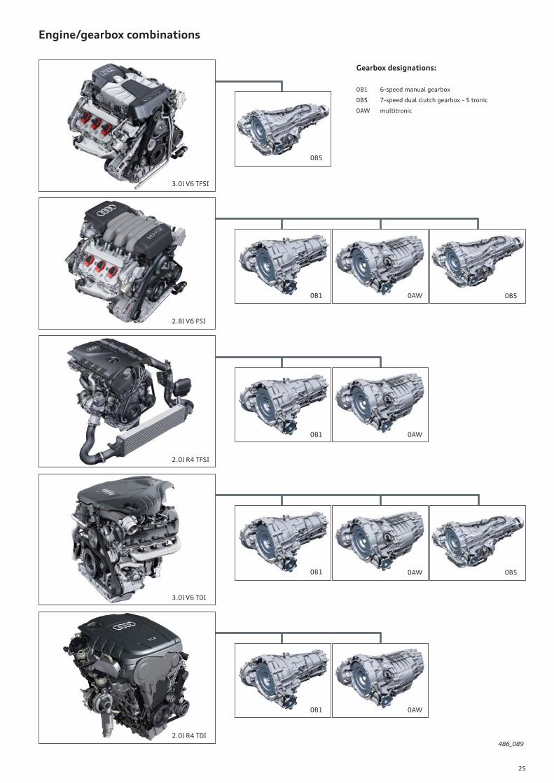
Engine/gearbox combinations
3.0l V6 TFSI
2.0l R4 TDI
3.0l V6 TDI
2.8l V6 FSI
2.0l R4 TFSI
0B1 0B50AW
0B1 0AW
0B5
0B1 0AW
0B1 0B50AW
Gearbox designations:
0B1 6-speed manual gearbox
0B5 7-speed dual clutch gearbox – S tronic
0AW multitronic
486_089
26
Reference
The drive concept of the Audi A6 ’11 is identical to that of the Audi A7 Sportback and also, in many respects, to that of the B8
series (Audi A4 ’08/A5). For information about the axle position and the new sealing and assembly concept of the axle fl ange
for the rear axle diff erential, refer to SSPs 392 and 409 as well as Audi iTV programme "Audi A5 Power Transmission" (broad-
cast 02.2010). This information also applies to the Audi A6 ’11 and represents basic knowledge of this topic.
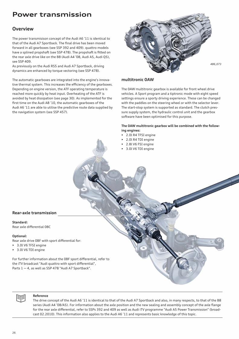
Overview
The power transmisison concept of the Audi A6 ’11 is identical to
that of the Audi A7 Sportback. The fi nal drive has been moved
forward in all gearboxes (see SSP 392 and 409). quattro models
have a splined propshaft (see SSP 478). The propshaft is fi tted on
the rear axle drive like on the B8 (Audi A4 ’08, Audi A5, Audi Q5),
see SSP 409.
As previously on the Audi RS5 and Audi A7 Sportback, driving
dynamics are enhanced by torque vectoring (see SSP 478).
The automatic gearboxes are integrated into the engine's innova-
tive thermal system. This increases the effi ciency of the gearboxes.
Depending on engine version, the ATF operating temperature is
reached more quickly by heat input. Overheating of the ATF is
avoided by heat dissipation (see page 30). As implemented for the
fi rst time on the Audi A8 ’10, the automatic gearboxes of the
Audi A6 ’11 are able to utilise the predictive route data supplied by
the navigation system (see SSP 457).
Rear-axle transmission
Standard:
Rear axle diff erential 0BC
Optional:
Rear axle drive 0BF with sport diff erential for:
• 3.0l V6 TFSI engine
• 3.0l V6 TDI engine
For further information about the 0BF sport diff erential, refer to
the iTV broadcast "Audi quattro with sport diff erential",
Parts 1 — 4, as well as SSP 478 "Audi A7 Sportback".
486_073
multitronic 0AW
The 0AW multitronic gearbox is available for front wheel drive
vehicles. A Sport program and a tiptronic mode with eight speed
settings ensure a sporty driving experience. These can be changed
with the paddles on the steering wheel or with the selector lever.
The start-stop system is supported as standard. The clutch pres-
sure supply system, the hydraulic control unit and the gearbox
software have been optimised for this purpose.
The 0AW multitronic gearbox will be combined with the follow-
ing engines:
• 2.0l R4 TFSI engine
• 2.0l R4 TDI engine
• 2.8l V6 FSI engine
• 3.0l V6 TDI engine
Power transmission
27
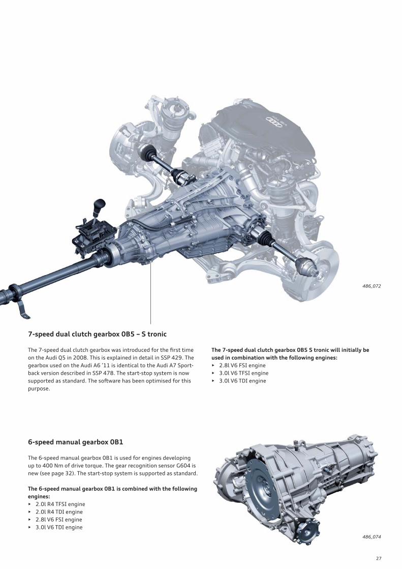
7-speed dual clutch gearbox 0B5 – S tronic
The 7-speed dual clutch gearbox was introduced for the fi rst time
on the Audi Q5 in 2008. This is explained in detail in SSP 429. The
gearbox used on the Audi A6 ’11 is identical to the Audi A7 Sport-
back version described in SSP 478. The start-stop system is now
supported as standard. The software has been optimised for this
purpose.
486_072
486_074
6-speed manual gearbox 0B1
The 6-speed manual gearbox 0B1 is used for engines developing
up to 400 Nm of drive torque. The gear recognition sensor G604 is
new (see page 32). The start-stop system is supported as standard.
The 6-speed manual gearbox 0B1 is combined with the following
engines:
• 2.0l R4 TFSI engine
• 2.0l R4 TDI engine
• 2.8l V6 FSI engine
• 3.0l V6 TDI engine
The 7-speed dual clutch gearbox 0B5 S tronic will initially be
used in combination with the following engines:
• 2.8l V6 FSI engine
• 3.0l V6 TFSI engine
• 3.0l V6 TDI engine

28
ATF heating/cooling
The software for the innovative thermal management system is
installed in engine control unit J623. The ATF temperature is
indicated to the software by the gearbox control unit J217.
The innovative thermal management system controls heating and
cooling of the ATF. For this purpose, the engine control unit
instructs the gearbox control unit to open or close the gearbox oil
cooling valve N509.
486_068
On models with the following engines, the innovative thermal
management system facilitates both ATF cooling and heating.
• 2.0l R4 TDI engine
• 3.0l V6 TDI engine
• 2.8l V6 FSI engine
• 3.0l V6 TFSI engine
The coolant circuit of the 3.0l V6 TDSI engine is shown here for
explanatory purposes:
Legend:
G62 Coolant temperature sender
G694 Temperature sender for engine temperature control
F265 Mapped engine cooling thermostat1)
(initial opening temperature: 87 °C)
J293 Radiator fan control unit1)
J671 Radiator fan control unit 21)
N489 Cylinder head coolant valve1), 4)
N509 Gearbox oil cooling valve 2)
V50 Coolant circulation pump3)
V188 Charge air cooling pump1)
1) activated by the engine control unit J6232) activated by the gearbox control unit J2173) activated by the Climatronic control unit J2554) actuates the coolant pump
1
2 V50
G694
4
2
6
G62F265
V188
N489
8
J671 J293
7
3
N509
5
2
5
9
10
11
1 Heater heat exchanger
2 Vent screw
3 Quicker coupler, black5)
4 ATF heat exchanger
5 Charge air cooler
6 Coolant expansion tank
7 Active coolant pump
8 Engine oil cooler
9 Radiator
10 Low temperature radiator
11 Auxiliary low temperature radiator
5) On models with a 2.8l V6 FSI engine, a grey quick coupler
with throttle is located in this position (see page 31).
Cooled coolant
Hot coolant
ATF
Cooled coolant
(charge air cooling)
Warm coolant
(charge air cooling)
29
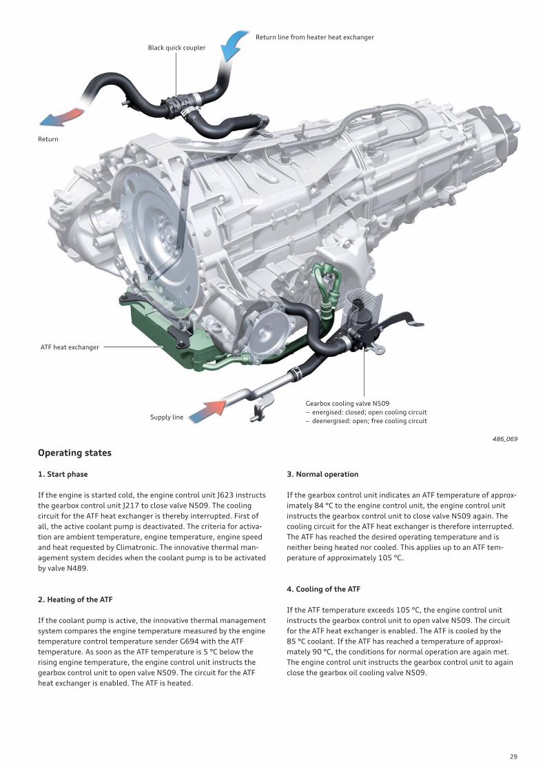
486_069
1. Start phase
If the engine is started cold, the engine control unit J623 instructs
the gearbox control unit J217 to close valve N509. The cooling
circuit for the ATF heat exchanger is thereby interrupted. First of
all, the active coolant pump is deactivated. The criteria for activa-
tion are ambient temperature, engine temperature, engine speed
and heat requested by Climatronic. The innovative thermal man-
agement system decides when the coolant pump is to be activated
by valve N489.
2. Heating of the ATF
If the coolant pump is active, the innovative thermal management
system compares the engine temperature measured by the engine
temperature control temperature sender G694 with the ATF
temperature. As soon as the ATF temperature is 5 °C below the
rising engine temperature, the engine control unit instructs the
gearbox control unit to open valve N509. The circuit for the ATF
heat exchanger is enabled. The ATF is heated.
3. Normal operation
If the gearbox control unit indicates an ATF temperature of approx-
imately 84 °C to the engine control unit, the engine control unit
instructs the gearbox control unit to close valve N509 again. The
cooling circuit for the ATF heat exchanger is therefore interrupted.
The ATF has reached the desired operating temperature and is
neither being heated nor cooled. This applies up to an ATF tem-
perature of approximately 105 °C.
4. Cooling of the ATF
If the ATF temperature exceeds 105 °C, the engine control unit
instructs the gearbox control unit to open valve N509. The circuit
for the ATF heat exchanger is enabled. The ATF is cooled by the
85 °C coolant. If the ATF has reached a temperature of approxi-
mately 90 °C, the conditions for normal operation are again met.
The engine control unit instructs the gearbox control unit to again
close the gearbox oil cooling valve N509.
Black quick coupler
Return line from heater heat exchanger
ATF heat exchanger
Supply line
Gearbox cooling valve N509
− energised: closed; open cooling circuit
− deenergised: open; free cooling circuit
Return
Operating states
30
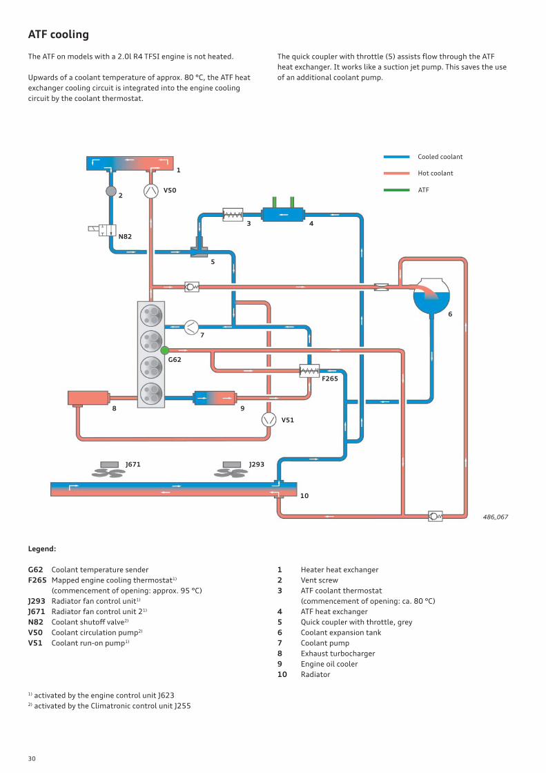
The ATF on models with a 2.0l R4 TFSI engine is not heated.
Upwards of a coolant temperature of approx. 80 °C, the ATF heat
exchanger cooling circuit is integrated into the engine cooling
circuit by the coolant thermostat.
The quick coupler with throttle (5) assists fl ow through the ATF
heat exchanger. It works like a suction jet pump. This saves the use
of an additional coolant pump.
486_067
Legend:
G62 Coolant temperature sender
F265 Mapped engine cooling thermostat1)
(commencement of opening: approx. 95 °C)
J293 Radiator fan control unit1)
J671 Radiator fan control unit 21)
N82 Coolant shutoff valve2)
V50 Coolant circulation pump2)
V51 Coolant run-on pump1)
1) activated by the engine control unit J6232) activated by the Climatronic control unit J255
1 Heater heat exchanger
2 Vent screw
3 ATF coolant thermostat
(commencement of opening: ca. 80 °C)
4 ATF heat exchanger
5 Quick coupler with throttle, grey
6 Coolant expansion tank
7 Coolant pump
8 Exhaust turbocharger
9 Engine oil cooler
10 Radiator
ATF cooling
1
2V50
N82
3 4
5
6
7
G62
F265
V51
8 9
J671 J293
10
Cooled coolant
Hot coolant
ATF
31
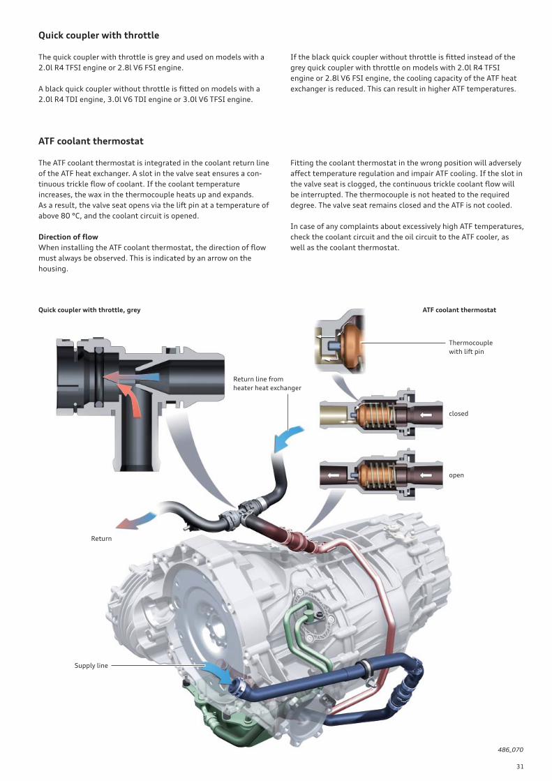
Quick coupler with throttle
The quick coupler with throttle is grey and used on models with a
2.0l R4 TFSI engine or 2.8l V6 FSI engine.
A black quick coupler without throttle is fi tted on models with a
2.0l R4 TDI engine, 3.0l V6 TDI engine or 3.0l V6 TFSI engine.
ATF coolant thermostat
The ATF coolant thermostat is integrated in the coolant return line
of the ATF heat exchanger. A slot in the valve seat ensures a con-
tinuous trickle fl ow of coolant. If the coolant temperature
increases, the wax in the thermocouple heats up and expands.
As a result, the valve seat opens via the lift pin at a temperature of
above 80 °C, and the coolant circuit is opened.
Direction of fl ow
When installing the ATF coolant thermostat, the direction of fl ow
must always be observed. This is indicated by an arrow on the
housing.
486_070
Quick coupler with throttle, grey
Return
Return line from
heater heat exchanger
ATF coolant thermostat
Supply line
If the black quick coupler without throttle is fi tted instead of the
grey quick coupler with throttle on models with 2.0l R4 TFSI
engine or 2.8l V6 FSI engine, the cooling capacity of the ATF heat
exchanger is reduced. This can result in higher ATF temperatures.
Fitting the coolant thermostat in the wrong position will adversely
aff ect temperature regulation and impair ATF cooling. If the slot in
the valve seat is clogged, the continuous trickle coolant fl ow will
be interrupted. The thermocouple is not heated to the required
degree. The valve seat remains closed and the ATF is not cooled.
In case of any complaints about excessively high ATF temperatures,
check the coolant circuit and the oil circuit to the ATF cooler, as
well as the coolant thermostat.
closed
open
Thermocouple
with lift pin

32
Gear recognition sensor G604
The gear recognition sensor G604 is used in 6-speed manual
gearbox 0B1 for the fi rst time with the Audi A6 ’11.
Tasks
The gear recognition sensor G604 assumes the previous functions
of the gear recognition switch F2081) and the gearbox neutral
position sender G701. It supports the following functions and
control units:
• Activation of the reversing lights
• Auto-dimming interior rearview mirror/external mirror and
external mirror fold-back function
• ParkAssist
• Trailer control unit
• Hill Start Assist (electrical parking brake)
• Audi hold assist (ESP)
• Recognition of neutral position for start-stop function
New features:
• Direct recognition of selected gear
• Gear recognition for the gearshift indicator (the selected gear
does not, however, appear on the driver information system
display until the clutch has closed)
• Enhanced shift comfort
1) was originally reversing light switch F4,
see SSP 392.
Functional principle
In the neutral position of the selector shaft, the gear recognition
sensor G604 is located directly over the centre member of the
diaphragm. This strengthens the magnetic fi eld of the sensor
considerably. The electronics can thus recognise the neutral posi-
tion.
When a gear is selected, the diaphragm section responsible for the
gear is located under the sensor.
The diaphragm sections assigned to each of the gears have diff er-
ent contours. The magnetic fi eld in the sensor is thus defl ected in
diff erent directions. In this way, the electronics can detect which
gear is selected.
If the shift cylinder diaphragm is damaged, the gears can no longer
be assigned clearly.
486_071
Gear recognition sensor
G604
Shift cylinder
Contour for locking bushes
Trim
Direction of magnetic fi eldCentre member
R 1 3 5
2 4 6
33
Enhanced shift comfort
The selected gear is now indicated quickly and directly to the
engine control unit J623. It no longer has to be computed from the
engine speed and vehicle speed. This has its advantages. When the
clutch closes, engine speed can now be adapted to the synchro-
nous speed depending on the speed of the vehicle. This allows a
signifi cant improvement in shift comfort.
For example, when shifting down from fourth into third gear on
models with a 2.8l V6 FSI engine, engine speed is initially reduced
to idle speed after fourth gear is disengaged. As soon as third gear
is determined to be engaged and the clutch starts to close, engine
speed is increased by the engine control unit up to the synchronous
speed corresponding to third gear. Closing of the clutch is detected
by the clutch position sender G476.
Diagnostics
Diagnostics are performed by the engine control unit J623. The
gear information is validated for the forward gears when the clutch
is closed and while vehicle speed is stable relative to engine speed.
The information for reverse gear is validated by the ESP signal
"reversing". The neutral position is validated when the vehicle is
stationary, the clutch is closed and the engine is idling.
Loss of signal or an entry into the event memory of the engine
control unit has the following eff ects:
• Start-stop function is not available
• Gear recognition for the gearshift indicator is delayed because it
is computed from the engine speed and the vehicle speed.
• Electronic parking brake is not released automatically when
driving away
• Audi hold assist is not available (see SSP 392)
• Reversing lights and park assist systems are not functional
• Shift comfort is reduced
• Event memory entries are made in the following control units:
• Control unit in dash panel insert J285
• Onboard power supply control unit J519
• Special vehicle control unit J608
If a gear is explicitly recognised after a loss of signal, the event
memory entry is set to "sporadic". Apart from supporting the
start-stop function, all tasks of the sensor are now executed. The
start-stop function is not supported until the next driving cycle.
Measured values
• Gear position sensor, raw value: Duty factor of PWM signal
• Neutral position 85.5 % — 86.5 %
• 1st gear 37.5 % — 38.5 %
• 2nd gear 53.5 % — 54.5 %
• 3rd gear 69.5 % — 70.5 %
• 4th gear 29.5 % — 30.5 %
• 5th gear 45.5 % — 46.5 %
• 6th gear 61.5 % — 62.5 %
• Reverse 13.5 % — 14.5 %
• Intermediate position1) 77.5 % — 78.5 %
• Internal sensor error 21.5 % — 22.5 % > replace sensor
• Gear position sensor, current value:
the gear currently recognised by the sensor, but still not set to
"valid" status
• Gear position sensor, last valid value:
the last gear evaluated as valid by the sensor
• Gear position sensor, gear position valid:
the gear recognised by the sensor and set to "valid" status
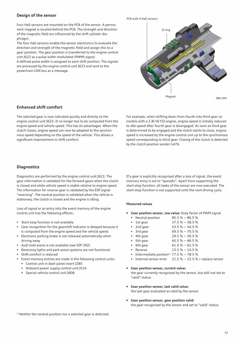
Design of the sensor
Four Hall sensors are mounted on the PCB of the sensor. A perma-
nent magnet is located behind the PCB. The strength and direction
of the magnetic fi eld are infl uenced by the shift cylinder dia-
phragm.
The four Hall sensors enable the sensor electronics to evaluate the
direction and strength of the magnetic fi eld and assign this to a
gear position. The gear position is transferred to the engine control
unit J623 as a pulse width modulated (PWM) signal.
A defi ned pulse width is assigned to each shift position. The signals
are processed by the engine control unit J623 and sent to the
powertrain CAN bus as a message.
486_093
O-ring
Magnet
PCB with 4 Hall sensors
1) Neither the neutral position nor a selected gear is detected.
34
Introduction
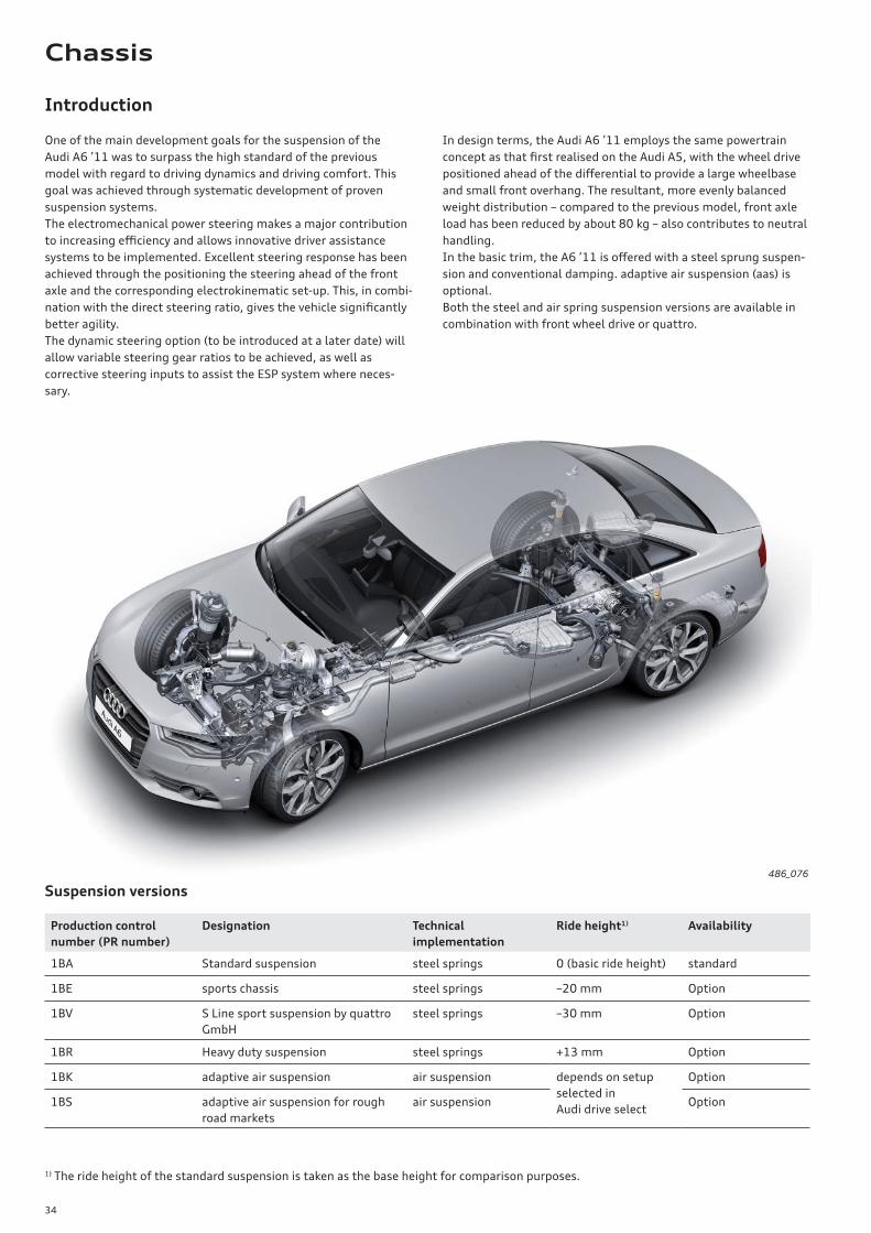
One of the main development goals for the suspension of the
Audi A6 ’11 was to surpass the high standard of the previous
model with regard to driving dynamics and driving comfort. This
goal was achieved through systematic development of proven
suspension systems.
The electromechanical power steering makes a major contribution
to increasing effi ciency and allows innovative driver assistance
systems to be implemented. Excellent steering response has been
achieved through the positioning the steering ahead of the front
axle and the corresponding electrokinematic set-up. This, in combi-
nation with the direct steering ratio, gives the vehicle signifi cantly
better agility.
The dynamic steering option (to be introduced at a later date) will
allow variable steering gear ratios to be achieved, as well as
corrective steering inputs to assist the ESP system where neces-
sary.
In design terms, the Audi A6 ’11 employs the same powertrain
concept as that fi rst realised on the Audi A5, with the wheel drive
positioned ahead of the diff erential to provide a large wheelbase
and small front overhang. The resultant, more evenly balanced
weight distribution – compared to the previous model, front axle
load has been reduced by about 80 kg – also contributes to neutral
handling.
In the basic trim, the A6 ’11 is off ered with a steel sprung suspen-
sion and conventional damping. adaptive air suspension (aas) is
optional.
Both the steel and air spring suspension versions are available in
combination with front wheel drive or quattro.
Production control
number (PR number)
Designation Technical
implementation
Ride height1) Availability
1BA Standard suspension steel springs 0 (basic ride height) standard
1BE sports chassis steel springs –20 mm Option
1BV S Line sport suspension by quattro
GmbH
steel springs –30 mm Option
1BR Heavy duty suspension steel springs +13 mm Option
1BK adaptive air suspension air suspension depends on setup
selected in
Audi drive select
Option
1BS adaptive air suspension for rough
road markets
air suspension Option
486_076
Suspension versions
1) The ride height of the standard suspension is taken as the base height for comparison purposes.
Chassis
35
Axles
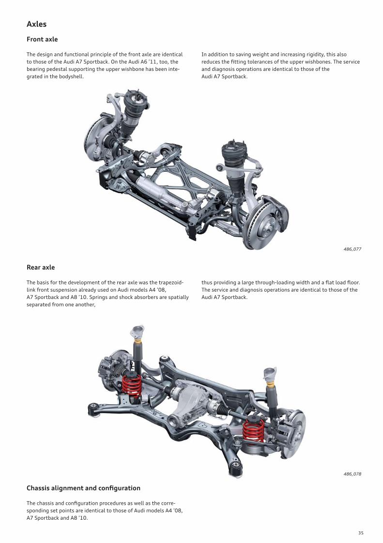
Front axle
The design and functional principle of the front axle are identical
to those of the Audi A7 Sportback. On the Audi A6 ’11, too, the
bearing pedestal supporting the upper wishbone has been inte-
grated in the bodyshell.
In addition to saving weight and increasing rigidity, this also
reduces the fi tting tolerances of the upper wishbones. The service
and diagnosis operations are identical to those of the
Audi A7 Sportback.
Rear axle
The basis for the development of the rear axle was the trapezoid-
link front suspension already used on Audi models A4 ’08,
A7 Sportback and A8 ’10. Springs and shock absorbers are spatially
separated from one another,
thus providing a large through-loading width and a fl at load fl oor.
The service and diagnosis operations are identical to those of the
Audi A7 Sportback.
486_078
486_077
Chassis alignment and confi guration
The chassis and confi guration procedures as well as the corre-
sponding set points are identical to those of Audi models A4 ’08,
A7 Sportback and A8 ’10.
36
486_079
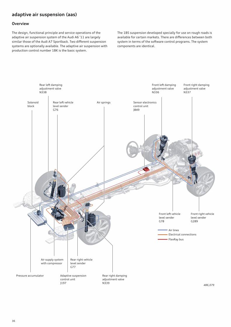
Solenoid
block
Rear left vehicle
level sender
G76
Sensor electronics
control unit
J849
Rear left damping
adjustment valve
N338
Air springs
Front right damping
adjustment valve
N337
Adaptive suspension
control unit
J197
Rear right damping
adjustment valve
N339
Front right vehicle
level sender
G289
Pressure accumulator
Rear right vehicle
level sender
G77
Air supply system
with compressor
Front left vehicle
level sender
G78
Front left damping
adjustment valve
N336
adaptive air suspension (aas)
Overview
The design, functional principle and service operations of the
adaptive air suspension system of the Audi A6 ’11 are largely
similar those of the Audi A7 Sportback. Two diff erent suspension
systems are optionally available. The adaptive air suspension with
production control number 1BK is the basic system.
The 1BS suspension developed specially for use on rough roads is
available for certain markets. There are diff erences between both
system in terms of the software control programs. The system
components are identical.
Electrical connections
Air lines
FlexRay bus
37
Steering system
Overview
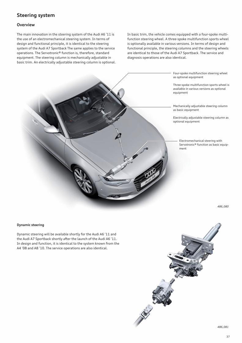
The main innovation in the steering system of the Audi A6 ’11 is
the use of an electromechanical steering system. In terms of
design and functional principle, it is identical to the steering
system of the Audi A7 Sportback The same applies to the service
operations. The Servotronic® function is, therefore, standard
equipment. The steering column is mechanically adjustable in
basic trim. An electrically adjustable steering column is optional.
In basic trim, the vehicle comes equipped with a four-spoke multi-
function steering wheel. A three-spoke multifunction sports wheel
is optionally available in various versions. In terms of design and
functional principle, the steering columns and the steering wheels
are identical to those of the Audi A7 Sportback. The service and
diagnosis operations are also identical.
486_080
Electromechanical steering with
Servotronic® function as basic equip-
ment
Mechanically adjustable steering column
as basic equipment
Electrically adjustable steering column as
optional equipment
Four-spoke multifunction steering wheel
as optional equipment
Three-spoke multifunction sports wheel is
available in various versions as optional
equipment
486_081
Dynamic steering
Dynamic steering will be available shortly for the Audi A6 ’11 and
the Audi A7 Sportback shortly after the launch of the Audi A6 ’11.
In design and function, it is identical to the system known from the
A4 ’08 and A8 ’10. The service operations are also identical.
38
Brake system
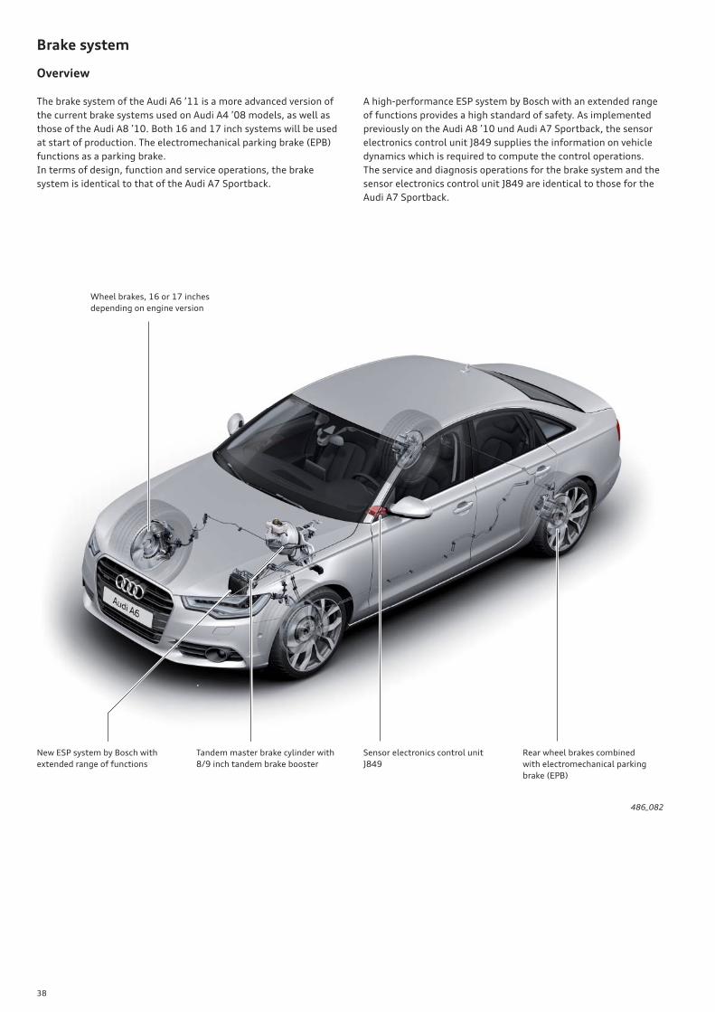
Overview
The brake system of the Audi A6 ’11 is a more advanced version of
the current brake systems used on Audi A4 ’08 models, as well as
those of the Audi A8 ’10. Both 16 and 17 inch systems will be used
at start of production. The electromechanical parking brake (EPB)
functions as a parking brake.
In terms of design, function and service operations, the brake
system is identical to that of the Audi A7 Sportback.
A high-performance ESP system by Bosch with an extended range
of functions provides a high standard of safety. As implemented
previously on the Audi A8 ’10 und Audi A7 Sportback, the sensor
electronics control unit J849 supplies the information on vehicle
dynamics which is required to compute the control operations.
The service and diagnosis operations for the brake system and the
sensor electronics control unit J849 are identical to those for the
Audi A7 Sportback.
486_082
New ESP system by Bosch with
extended range of functions
Rear wheel brakes combined
with electromechanical parking
brake (EPB)
Sensor electronics control unit
J849
Tandem master brake cylinder with
8/9 inch tandem brake booster
Wheel brakes, 16 or 17 inches
depending on engine version

39
Wheel brakes
16 and 17 inch brake systems are used depending on engine
power.
This brake system delivers outstanding braking performance.
Engine type 2.0l R4 TFSI – 132 kW
2.8l V6 FSI – 150 kW
2.0l R4 TDI – 130 kW
3.0l V6 TDI – 150 kW
3.0l V6 TDI – 180 kW 3.0l V6 TFSI – 220 kW
Brake type TRW FBC 60 16“ TRW FBC 60 17“ Teves FNR 42 AL
Minimum wheel size 16 inch 17 inch 17 inch
Number of pistons 1 1 2
Piston diameter 60 mm 60 mm 42 mm
Brake disc diameter 320 mm 345 mm 356 mm
Front wheel brake
Depending on engine version, three diff erent brake systems are
used on the front axle.
Rear wheel
Depending on engine version, two diff erent brake systems are used
on the rear axle.
Engine type 2.0l R4 TFSI – 132 kW
2.8l V6 FSI – 150 kW
2.0l R4 TDI – 130 kW
3.0l V6 TDI – 150 kW
3.0l V6 TFSI – 220 kW
3.0l V6 TDI – 180 kW
Brake type CII 43, EPB 16“ CII 43, EPB 17“
Minimum wheel size 16 inch 17 inch
Number of pistons 1 1
Piston diameter 43 mm 43 mm
Brake disc diameter 300 mm 330 mm
486_083
486_084
40
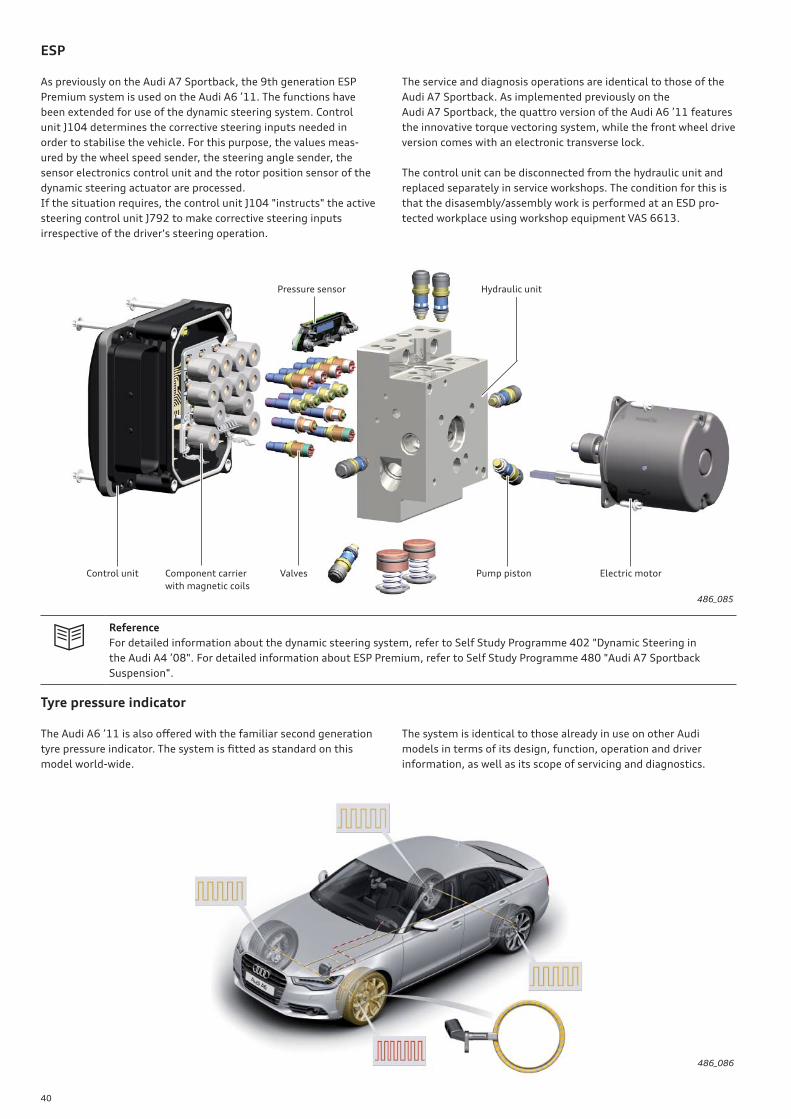
ESP
As previously on the Audi A7 Sportback, the 9th generation ESP
Premium system is used on the Audi A6 ’11. The functions have
been extended for use of the dynamic steering system. Control
unit J104 determines the corrective steering inputs needed in
order to stabilise the vehicle. For this purpose, the values meas-
ured by the wheel speed sender, the steering angle sender, the
sensor electronics control unit and the rotor position sensor of the
dynamic steering actuator are processed.
If the situation requires, the control unit J104 "instructs" the active
steering control unit J792 to make corrective steering inputs
irrespective of the driver's steering operation.
The service and diagnosis operations are identical to those of the
Audi A7 Sportback. As implemented previously on the
Audi A7 Sportback, the quattro version of the Audi A6 ’11 features
the innovative torque vectoring system, while the front wheel drive
version comes with an electronic transverse lock.
The control unit can be disconnected from the hydraulic unit and
replaced separately in service workshops. The condition for this is
that the disasembly/assembly work is performed at an ESD pro-
tected workplace using workshop equipment VAS 6613.
486_085
Reference
For detailed information about the dynamic steering system, refer to Self Study Programme 402 "Dynamic Steering in
the Audi A4 ’08". For detailed information about ESP Premium, refer to Self Study Programme 480 "Audi A7 Sportback
Suspension".
Pressure sensor Hydraulic unit
Electric motorPump pistonValvesComponent carrier
with magnetic coils
Control unit
Tyre pressure indicator
The Audi A6 ’11 is also off ered with the familiar second generation
tyre pressure indicator. The system is fi tted as standard on this
model world-wide.
The system is identical to those already in use on other Audi
models in terms of its design, function, operation and driver
information, as well as its scope of servicing and diagnostics.
486_086
41
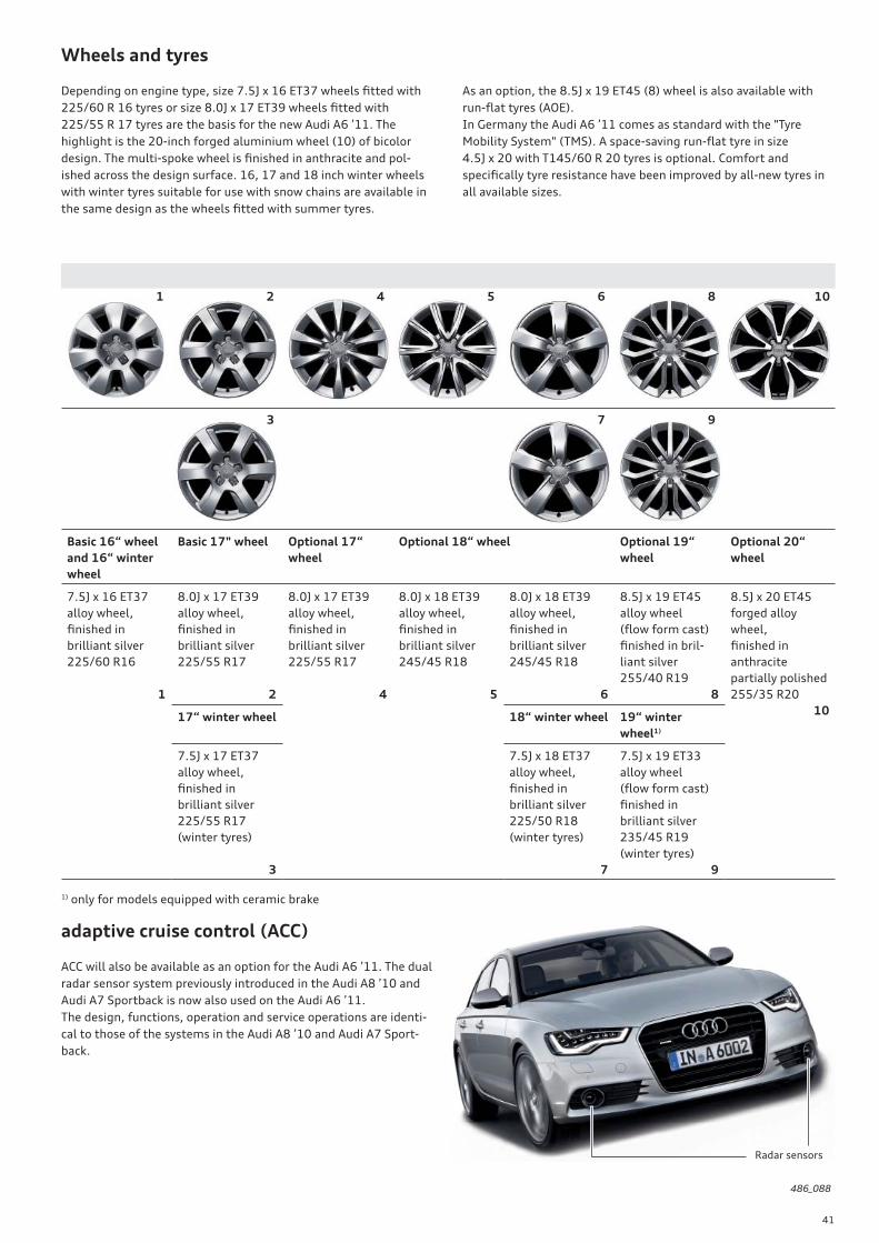
Wheels and tyres
Depending on engine type, size 7.5J x 16 ET37 wheels fi tted with
225/60 R 16 tyres or size 8.0J x 17 ET39 wheels fi tted with
225/55 R 17 tyres are the basis for the new Audi A6 ’11. The
highlight is the 20-inch forged aluminium wheel (10) of bicolor
design. The multi-spoke wheel is fi nished in anthracite and pol-
ished across the design surface. 16, 17 and 18 inch winter wheels
with winter tyres suitable for use with snow chains are available in
the same design as the wheels fi tted with summer tyres.
Basic 16“ wheel
and 16“ winter
wheel
Basic 17" wheel Optional 17“
wheel
Optional 18“ wheel Optional 19“
wheel
Optional 20“
wheel
7.5J x 16 ET37
alloy wheel,
fi nished in
brilliant silver
225/60 R16
1
8.0J x 17 ET39
alloy wheel,
fi nished in
brilliant silver
225/55 R17
2
8.0J x 17 ET39
alloy wheel,
fi nished in
brilliant silver
225/55 R17
4
8.0J x 18 ET39
alloy wheel,
fi nished in
brilliant silver
245/45 R18
5
8.0J x 18 ET39
alloy wheel,
fi nished in
brilliant silver
245/45 R18
6
8.5J x 19 ET45
alloy wheel
(fl ow form cast)
fi nished in bril-
liant silver
255/40 R19
8
8.5J x 20 ET45
forged alloy
wheel,
fi nished in
anthracite
partially polished
255/35 R20
1017“ winter wheel 18“ winter wheel 19“ winter
wheel1)
7.5J x 17 ET37
alloy wheel,
fi nished in
brilliant silver
225/55 R17
(winter tyres)
3
7.5J x 18 ET37
alloy wheel,
fi nished in
brilliant silver
225/50 R18
(winter tyres)
7
7.5J x 19 ET33
alloy wheel
(fl ow form cast)
fi nished in
brilliant silver
235/45 R19
(winter tyres)
9
2 4 5
3
1
adaptive cruise control (ACC)
ACC will also be available as an option for the Audi A6 ’11. The dual
radar sensor system previously introduced in the Audi A8 ’10 and
Audi A7 Sportback is now also used on the Audi A6 ’11.
The design, functions, operation and service operations are identi-
cal to those of the systems in the Audi A8 ’10 and Audi A7 Sport-
back.
486_088
As an option, the 8.5J x 19 ET45 (8) wheel is also available with
run-fl at tyres (AOE).
In Germany the Audi A6 ’11 comes as standard with the "Tyre
Mobility System" (TMS). A space-saving run-fl at tyre in size
4.5J x 20 with T145/60 R 20 tyres is optional. Comfort and
specifi cally tyre resistance have been improved by all-new tyres in
all available sizes.
6
7
8
9
10
Radar sensors
1) only for models equipped with ceramic brake
42
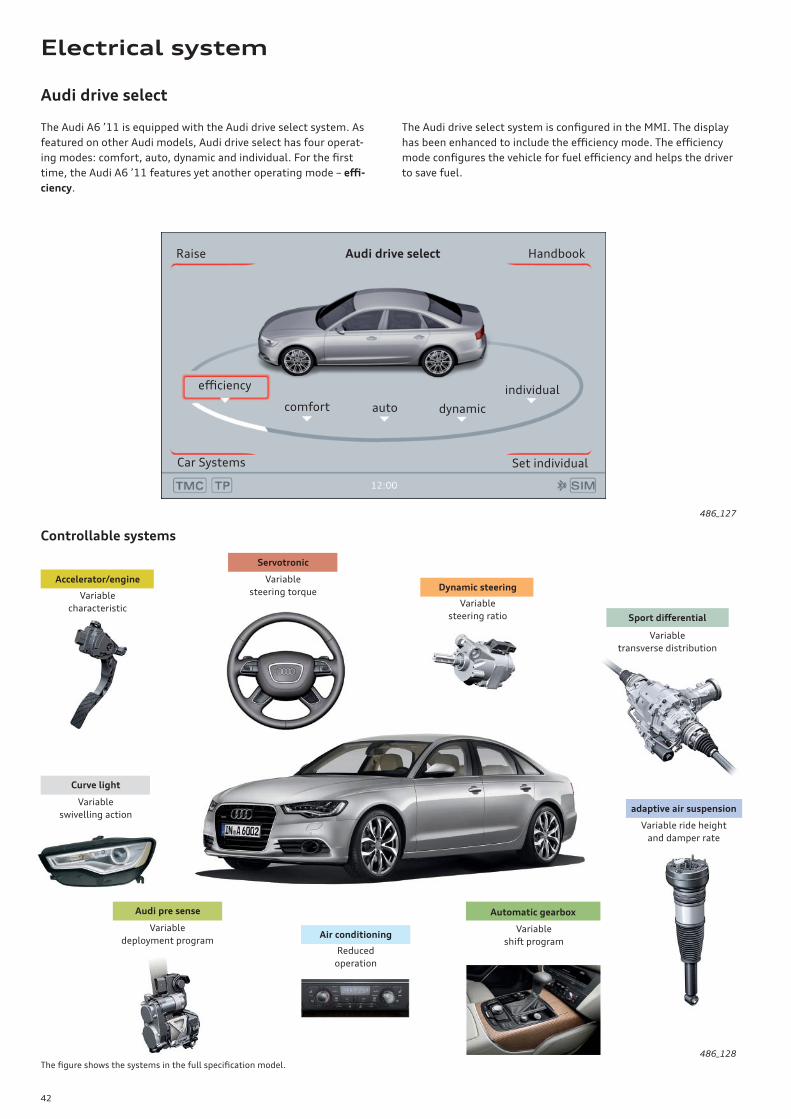
Audi drive select
The Audi drive select system is confi gured in the MMI. The display
has been enhanced to include the effi ciency mode. The effi ciency
mode confi gures the vehicle for fuel effi ciency and helps the driver
to save fuel.
The Audi A6 ’11 is equipped with the Audi drive select system. As
featured on other Audi models, Audi drive select has four operat-
ing modes: comfort, auto, dynamic and individual. For the fi rst
time, the Audi A6 ’11 features yet another operating mode – effi -
ciency.
Controllable systems
486_127
486_128
Audi pre sense
Sport diff erential
Automatic gearbox
Curve light
Accelerator/engine
adaptive air suspension
Servotronic
Variable
deployment program
Variable
transverse distribution
Variable
shift program
Variable
swivelling action
Variable
characteristic
Variable ride height
and damper rate
Variable
steering torque
The fi gure shows the systems in the full specifi cation model.
Air conditioning
Reduced
operation
Dynamic steering
Variable
steering ratio
autocomfort
Car Systems
Raise
effi ciency
dynamic
individual
Handbook
Set individual
Audi drive select
Electrical system
43
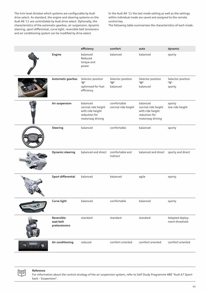
The trim level dictates which systems are confi gurable by Audi
drive select. As standard, the engine and steering systems on the
Audi A6 ’11 are controllable by Audi drive select. Optionally, the
characteristics of the automatic gearbox, air suspension, dynamic
steering, sport diff erential, curve light, reversible belt tensioners
and air conditioning system can be modifi ed by drive select.
In the Audi A6 ’11 the last mode setting as well as the settings
within individual mode are saved and assigned to the remote
control key.
The following table summarises the characteristics of each mode.
effi ciency comfort auto dynamic
Engine balanced
Reduced
torque and
power
balanced balanced sporty
Automatic gearbox Selector position
"E"
optimised for fuel
effi ciency
Selector position
"D"
balanced
Selector position
"D"
balanced
Selector position
"S"
sporty
Air suspension balanced
normal ride height
with ride height
reduction for
motorway driving
comfortable
normal ride height
balanced
normal ride height
with ride height
reduction for
motorway driving
sporty
low ride height
Steering balanced comfortable balanced sporty
Dynamic steering balanced and direct comfortable and
indirect
balanced and direct sporty and direct
Sport diff erential balanced balanced agile sporty
Curve light balanced comfortable balanced sporty
Reversible
seat-belt
pretensioners
standard standard standard Adapted deploy-
ment threshold
Air conditioning reduced comfort oriented comfort oriented comfort oriented
Reference
For information about the control strategy of the air suspension system, refer to Self Study Programme 480 "Audi A7 Sport-
back – Suspension".
44
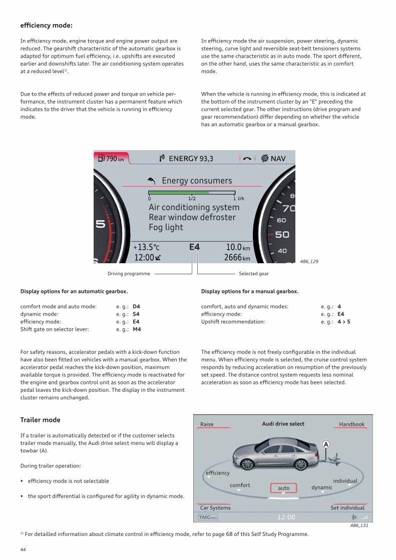
Due to the eff ects of reduced power and torque on vehicle per-
formance, the instrument cluster has a permanent feature which
indicates to the driver that the vehicle is running in effi ciency
mode.
In effi ciency mode, engine torque and engine power output are
reduced. The gearshift characteristic of the automatic gearbox is
adapted for optimum fuel effi ciency, i.e. upshifts are executed
earlier and downshifts later. The air conditioning system operates
at a reduced level1).
Display options for an automatic gearbox.
comfort mode and auto mode: e. g.: D4
dynamic mode: e. g.: S4
effi ciency mode: e. g.: E4
Shift gate on selector lever: e. g.: M4
Display options for a manual gearbox.
comfort, auto and dynamic modes: e. g.: 4
effi ciency mode: e. g.: E4
Upshift recommendation: e. g.: 4 > 5
Trailer mode
If a trailer is automatically detected or if the customer selects
trailer mode manually, the Audi drive select menu will display a
towbar (A).
During trailer operation:
• effi ciency mode is not selectable
• the sport diff erential is confi gured for agility in dynamic mode.
effi ciency mode:
In effi ciency mode the air suspension, power steering, dynamic
steering, curve light and reversible seat-belt tensioners systems
use the same characteristic as in auto mode. The sport diff erent,
on the other hand, uses the same characteristic as in comfort
mode.
When the vehicle is running in effi ciency mode, this is indicated at
the bottom of the instrument cluster by an "E" preceding the
current selected gear. The other instructions (drive program and
gear recommendation) diff er depending on whether the vehicle
has an automatic gearbox or a manual gearbox.
486_129
486_131
1) For detailled information about climate control in effi ciency mode, refer to page 68 of this Self Study Programme.
For safety reasons, accelerator pedals with a kick-down function
have also been fi tted on vehicles with a manual gearbox. When the
accelerator pedal reaches the kick-down position, maximum
available torque is provided. The effi ciency mode is reactivated for
the engine and gearbox control unit as soon as the accelerator
pedal leaves the kick-down position. The display in the instrument
cluster remains unchanged.
The effi ciency mode is not freely confi gurable in the individual
menu. When effi ciency mode is selected, the cruise control system
responds by reducing acceleration on resumption of the previously
set speed. The distance control system requests less nominal
acceleration as soon as effi ciency mode has been selected.
autocomfort dynamic
individual
Handbook
Car Systems Set individual
Raise
effi ciency
Selected gearDriving programme
E4
Energy consumers
Air conditioning systemRear window defrosterFog light
Audi drive select
45
486_132
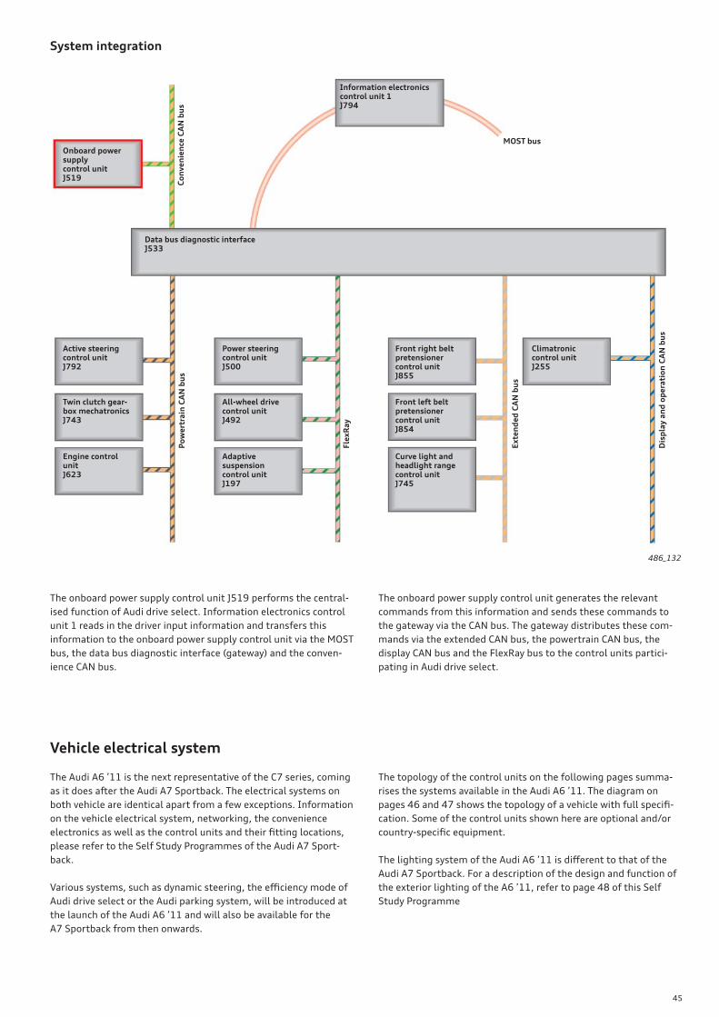
System integration
Onboard power supply control unitJ519
Data bus diagnostic interfaceJ533
Information electronicscontrol unit 1J794
Front right beltpretensioner control unit J855
Front left beltpretensioner control unit J854
Curve light and headlight rangecontrol unitJ745
All-wheel drivecontrol unitJ492
Adaptive suspensioncontrol unitJ197
Engine control unitJ623
Active steering control unitJ792
Twin clutch gear-box mechatronicsJ743
Co
nv
en
ien
ce C
AN
bu
sP
ow
ert
rain
CA
N b
us
Fle
xR
ay
Ex
ten
de
d C
AN
bu
s
MOST bus
Power steering control unitJ500
Climatronic control unitJ255
Dis
pla
y a
nd
op
era
tio
n C
AN
bu
s
The onboard power supply control unit J519 performs the central-
ised function of Audi drive select. Information electronics control
unit 1 reads in the driver input information and transfers this
information to the onboard power supply control unit via the MOST
bus, the data bus diagnostic interface (gateway) and the conven-
ience CAN bus.
The onboard power supply control unit generates the relevant
commands from this information and sends these commands to
the gateway via the CAN bus. The gateway distributes these com-
mands via the extended CAN bus, the powertrain CAN bus, the
display CAN bus and the FlexRay bus to the control units partici-
pating in Audi drive select.
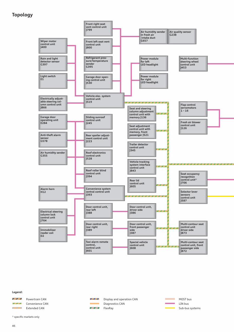
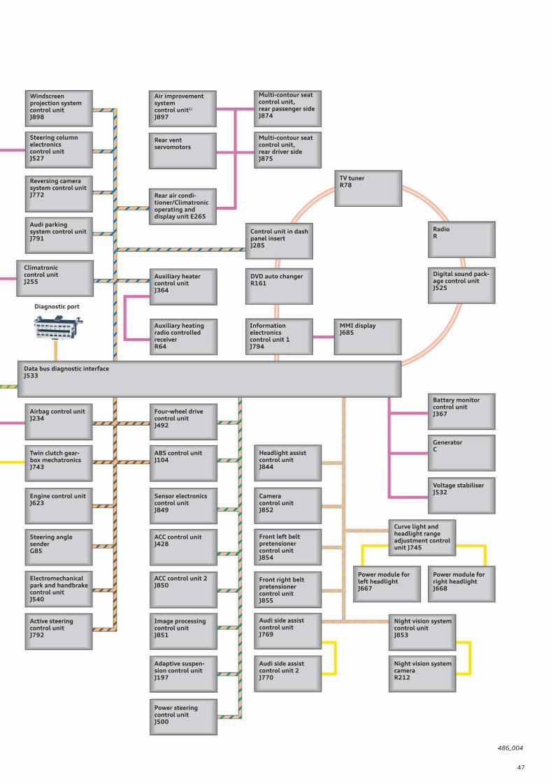
The topology of the control units on the following pages summa-
rises the systems available in the Audi A6 ’11. The diagram on
pages 46 and 47 shows the topology of a vehicle with full specifi -
cation. Some of the control units shown here are optional and/or
country-specifi c equipment.
The lighting system of the Audi A6 ’11 is diff erent to that of the
Audi A7 Sportback. For a description of the design and function of
the exterior lighting of the A6 ’11, refer to page 48 of this Self
Study Programme
The Audi A6 ’11 is the next representative of the C7 series, coming
as it does after the Audi A7 Sportback. The electrical systems on
both vehicle are identical apart from a few exceptions. Information
on the vehicle electrical system, networking, the convenience
electronics as well as the control units and their fi tting locations,
please refer to the Self Study Programmes of the Audi A7 Sport-
back.
Various systems, such as dynamic steering, the effi ciency mode of
Audi drive select or the Audi parking system, will be introduced at
the launch of the Audi A6 ’11 and will also be available for the
A7 Sportback from then onwards.
Vehicle electrical system
46
Topology
Convenience CAN
Powertrain CAN Display and operation CAN
Diagnostics CAN
Extended CAN FlexRay
MOST bus
LIN bus
Sub-bus systems
Wiper motor control unitJ400
Rear spoiler adjust-ment control unitJ223
Sliding sunroof control unitJ245
Vehicle elec. system control unitJ519
Garage door open-ing control unitJ530
Refrigerant pres-sure/temperature senderG395
Air quality sensorG238
Air humidity sender in fresh air intake ductG657
Immobiliser reader coilD2
Electrical steering column lock control unitJ764
Alarm hornH12
Air humidity senderG355
Anti-theft alarm sensorG578
Garage door operating unitE284
Electrically adjust-able steering col-umn control unitJ866
Light switchE1
Rain and light detector sensor G397
Selector lever sensors control unitJ587
Special vehicle control unitJ608
Door control unit, driver sideJ386
Rear lid control unitJ605
Vehicle tracking system interface control unitJ843
Trailer detector control unitJ345
Seat adjustment control unit with memory, front passenger J521
Seat and steering column adjustment control unit with memory J136
Taxi alarm remote control, control unitJ601
Door control unit, rear rightJ389
Door control unit, rear leftJ388
Convenience system central control unitJ393
Roof roller blind control unitJ394
Roof electronics control unitJ528
Door control unit, front passenger sideJ387
Multi-contour seat control unitdriver sideJ873
Multi-contour seat control unit, front passenger sideJ872
Fresh air blower control unitJ126
Flap control servomotors1 – 16
Multi-function steering wheel control unitJ453
Power module for right LED headlight
Power module for left LED headlight
Front right seat vent control unitJ799
Front left seat vent control unitJ800
Seat occupancy recognition control unit1)
J706
1) specifi c markets only
Legend:
47
486_004
Audi parking system control unitJ791
Reversing camera system control unitJ772
Steering column electronics control unitJ527
Windscreen projection system control unitJ898
Front left belt pretensioner control unitJ854
Camera control unitJ852
Headlight assist control unitJ844
Adaptive suspen-sion control unitJ197
Image processing control unitJ851
ACC control unit 2J850
ACC control unitJ428
Sensor electronics control unitJ849
ABS control unitJ104
Four-wheel drivecontrol unitJ492
Night vision system cameraR212
Night vision system control unitJ853
Power module for right headlightJ668
Power module for left headlightJ667
Curve light and headlight range adjustment control unit J745
Voltage stabiliserJ532
GeneratorC
Battery monitor control unitJ367
Twin clutch gear-box mechatronicsJ743
Electromechanical park and handbrake control unitJ540
Steering angle senderG85
Engine control unitJ623
Power steering control unitJ500
MMI displayJ685
Digital sound pack-age control unitJ525
RadioR
Information electronics control unit 1J794
DVD auto changerR161
Control unit in dash panel insertJ285
Auxiliary heater control unitJ364
TV tunerR78
Rear air condi-tioner/Climatronic operating and display unit E265
Rear vent servomotors
Airbag control unitJ234
Data bus diagnostic interfaceJ533
Climatronic control unitJ255
Audi side assist control unit 2J770
Audi side assist control unitJ769
Front right belt pretensioner control unitJ855
Auxiliary heating radio controlled receiverR64
Diagnostic port
Active steering control unitJ792
Air improvement system control unit1)
J897
Multi-contour seat control unit, rear passenger side J874
Multi-contour seat control unit, rear driver sideJ875
48
Exterior lighting
486_048
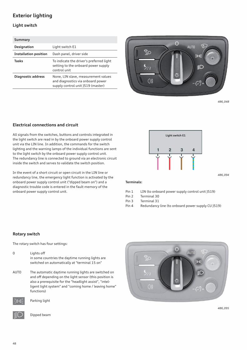
Summary
Designation Light switch E1
Installation position Dash panel, driver side
Tasks To indicate the driver's preferred light
setting to the onboard power supply
control unit
Diagnostic address None, LIN slave, measurement values
and diagnostics via onboard power
supply control unit J519 (master)
Lights off
in some countries the daytime running lights are
switched on automatically at "terminal 15 on"
The automatic daytime running lights are switched on
and off depending on the light sensor (this position is
also a prerequisite for the "headlight assist", "intel-
ligent light system" and "coming home / leaving home"
functions)
Parking light
Dipped beam
0
AUTO
Electrical connections and circuit
All signals from the switches, buttons and controls integrated in
the light switch are read in by the onboard power supply control
unit via the LIN line. In addition, the commands for the switch
lighting and the warning lamps of the individual functions are sent
to the light switch by the onboard power supply control unit.
The redundancy line is connected to ground via an electronic circuit
inside the switch and serves to validate the switch position.
In the event of a short circuit or open circuit in the LIN line or
redundancy line, the emergency light function is activated by the
onboard power supply control unit ("dipped beam on") and a
diagnostic trouble code is entered in the fault memory of the
onboard power supply control unit.
Terminals:
Pin 1 LIN (to onboard power supply control unit J519)
Pin 2 Terminal 30
Pin 3 Terminal 31
Pin 4 Redundancy line (to onboard power supply CU J519)
486_094
Light switch E1
Rotary switch
The rotary switch has four settings:
Light switch
486_095
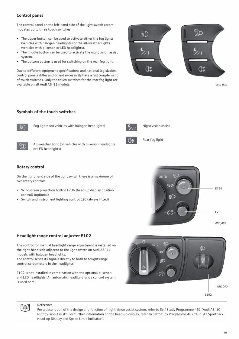
49
Control panel
The control panel on the left-hand side of the light switch accom-
modates up to three touch switches:
• The upper button can be used to activate either the fog lights
(vehicles with halogen headlights) or the all-weather lights
(vehicles with bi-xenon or LED headlights).
• The middle button can be used to activate the night vision assist
system.
• The bottom button is used for switching on the rear fog light.
Due to diff erent equipment specifi cations and national legislation,
control panels diff er and do not necessarily have a full complement
of touch switches. Only the touch switches for the rear fog light are
available on all Audi A6 ’11 models.
Fog lights (on vehicles with halogen headlights)
All-weather light (on vehicles with bi-xenon headlights
or LED headlights)
Reference
For a description of the design and function of night vision assist system, refer to Self Study Programme 462 "Audi A8 ’10
Night Vision Assist". For further information on the head-up display, refer to Self Study Programme 482 "Audi A7 Sportback
Head-up Display and Speed Limit Indicator".
486_040
486_097
486_096
Symbols of the touch switches
Night vision assist
Rear fog light
Rotary control
On the right hand side of the light switch there is a maximum of
two rotary controls:
• Windscreen projection button E736 (head-up display position
control) (optional)
• Switch and instrument lighting control E20 (always fi tted)
Headlight range control adjuster E102
The control for manual headlight range adjustment is installed on
the right-hand side adjacent to the light switch on Audi A6 ’11
models with halogen headlights.
The control sends its signals directly to both headlight range
control servomotors in the headlights.
E102 is not installed in combination with the optional bi-xenon
and LED headlights. An automatic headlight range control system
is used here.
E102
E20
E736
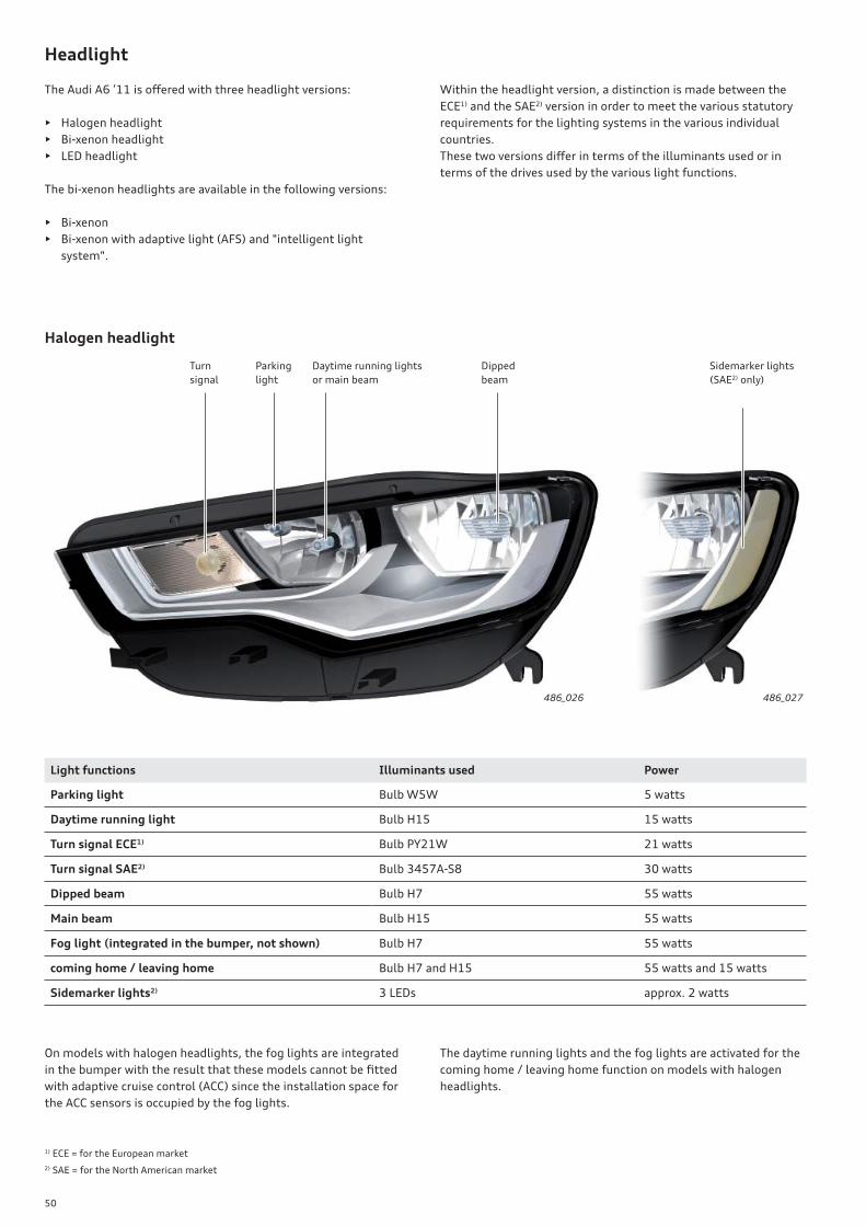
50
Headlight
The Audi A6 ’11 is off ered with three headlight versions:
• Halogen headlight
• Bi-xenon headlight
• LED headlight
The bi-xenon headlights are available in the following versions:
• Bi-xenon
• Bi-xenon with adaptive light (AFS) and "intelligent light
system".
Within the headlight version, a distinction is made between the
ECE1) and the SAE2) version in order to meet the various statutory
requirements for the lighting systems in the various individual
countries.
These two versions diff er in terms of the illuminants used or in
terms of the drives used by the various light functions.
Halogen headlight
Parking
light
Dipped
beam
Turn
signal
Daytime running lights
or main beam
Sidemarker lights
( SAE2) only)
1) ECE = for the European market
2) SAE = for the North American market
486_026 486_027
On models with halogen headlights, the fog lights are integrated
in the bumper with the result that these models cannot be fi tted
with adaptive cruise control (ACC) since the installation space for
the ACC sensors is occupied by the fog lights.
The daytime running lights and the fog lights are activated for the
coming home / leaving home function on models with halogen
headlights.
Light functions Illuminants used Power
Parking light Bulb W5W 5 watts
Daytime running light Bulb H15 15 watts
Turn signal ECE1) Bulb PY21W 21 watts
Turn signal SAE2) Bulb 3457A-S8 30 watts
Dipped beam Bulb H7 55 watts
Main beam Bulb H15 55 watts
Fog light (integrated in the bumper, not shown) Bulb H7 55 watts
coming home / leaving home Bulb H7 and H15 55 watts and 15 watts
Sidemarker lights2) 3 LEDs approx. 2 watts
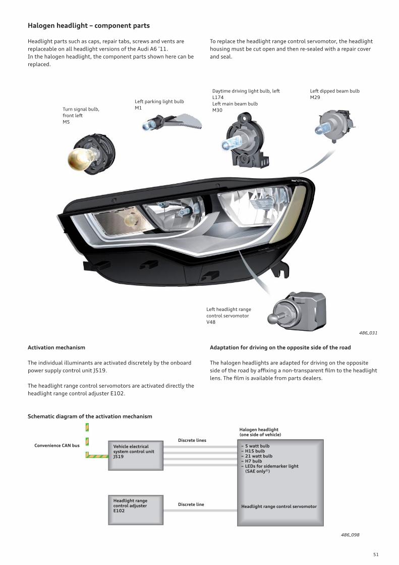
51
Halogen headlight – component parts
486_031
Turn signal bulb,
front left
M5
Daytime driving light bulb, left
L174
Left main beam bulb
M30
Left headlight range
control servomotor
V48
Left dipped beam bulb
M29Left parking light bulb
M1
Headlight parts such as caps, repair tabs, screws and vents are
replaceable on all headlight versions of the Audi A6 ’11.
In the halogen headlight, the component parts shown here can be
replaced.
To replace the headlight range control servomotor, the headlight
housing must be cut open and then re-sealed with a repair cover
and seal.
Activation mechanism
The individual illuminants are activated discretely by the onboard
power supply control unit J519.
The headlight range control servomotors are activated directly the
headlight range control adjuster E102.
Adaptation for driving on the opposite side of the road
The halogen headlights are adapted for driving on the opposite
side of the road by affi xing a non-transparent fi lm to the headlight
lens. The fi lm is available from parts dealers.
Schematic diagram of the activation mechanism
486_098
Convenience CAN bus – 5 watt bulb – H15 bulb– 21 watt bulb– H7 bulb– LEDs for sidemarker light (SAE only2))
Headlight range control servomotor
Headlight range control adjusterE102
Discrete lines
Halogen headlight(one side of vehicle)
Vehicle electrical system control unitJ519
Discrete line
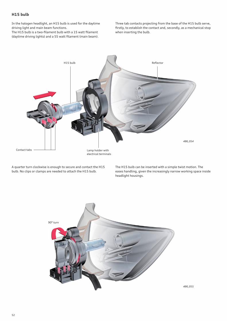
52
486_054
486_055
H15 bulb
In the halogen headlight, an H15 bulb is used for the daytime
driving light and main beam functions.
The H15 bulb is a two-fi lament bulb with a 15 watt fi lament
(daytime driving lights) and a 55 watt fi lament (main beam).
Three tab contacts projecting from the base of the H15 bulb serve,
fi rstly, to establish the contact and, secondly, as a mechanical stop
when inserting the bulb.
A quarter turn clockwise is enough to secure and contact the H15
bulb. No clips or clamps are needed to attach the H15 bulb.
The H15 bulb can be inserted with a simple twist motion. The
eases handling, given the increasingly narrow working space inside
headlight housings.
Contact tabs Lamp holder with
electrical terminals
H15 bulb Refl ector
90° turn
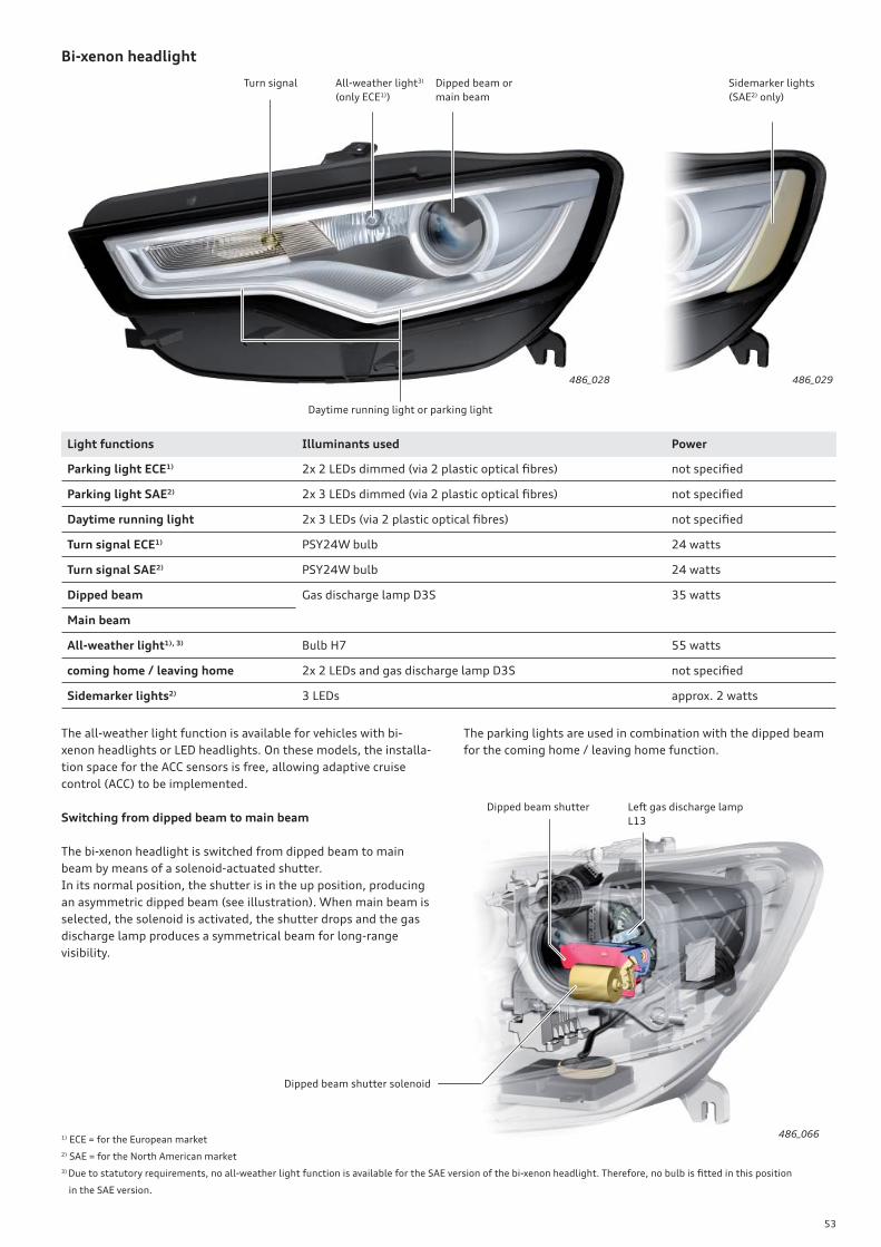
53
Bi-xenon headlight
Dipped beam or
main beam
Daytime running light or parking light
All-weather light3)
(only ECE1))
Light functions Illuminants used Power
Parking light ECE1) 2x 2 LEDs dimmed (via 2 plastic optical fi bres) not specifi ed
Parking light SAE2) 2x 3 LEDs dimmed (via 2 plastic optical fi bres) not specifi ed
Daytime running light 2x 3 LEDs (via 2 plastic optical fi bres) not specifi ed
Turn signal ECE1) PSY24W bulb 24 watts
Turn signal SAE2) PSY24W bulb 24 watts
Dipped beam Gas discharge lamp D3S 35 watts
Main beam
All-weather light1), 3) Bulb H7 55 watts
coming home / leaving home 2x 2 LEDs and gas discharge lamp D3S not specifi ed
Sidemarker lights2) 3 LEDs approx. 2 watts
Turn signal Sidemarker lights
( SAE2) only)
486_028 486_029
486_066
Left gas discharge lamp
L13
Dipped beam shutterSwitching from dipped beam to main beam
The bi-xenon headlight is switched from dipped beam to main
beam by means of a solenoid-actuated shutter.
In its normal position, the shutter is in the up position, producing
an asymmetric dipped beam (see illustration). When main beam is
selected, the solenoid is activated, the shutter drops and the gas
discharge lamp produces a symmetrical beam for long-range
visibility.
The all-weather light function is available for vehicles with bi-
xenon headlights or LED headlights. On these models, the installa-
tion space for the ACC sensors is free, allowing adaptive cruise
control (ACC) to be implemented.
The parking lights are used in combination with the dipped beam
for the coming home / leaving home function.
1) ECE = for the European market
2) SAE = for the North American market
3) Due to statutory requirements, no all-weather light function is available for the SAE version of the bi-xenon headlight. Therefore, no bulb is fi tted in this position
in the SAE version.
Dipped beam shutter solenoid
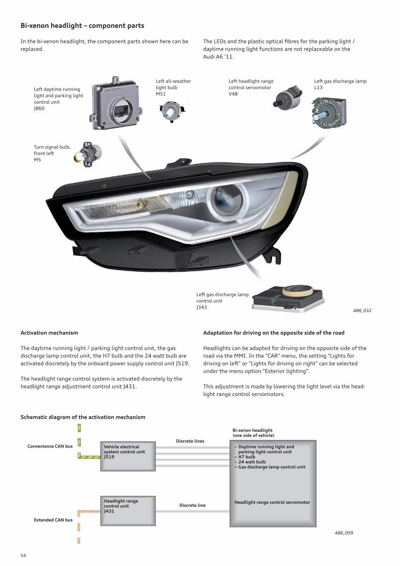
54
Bi-xenon headlight – component parts
In the bi-xenon headlight, the component parts shown here can be
replaced.
The LEDs and the plastic optical fi bres for the parking light /
daytime running light functions are not replaceable on the
Audi A6 ’11.
486_032
Left daytime running
light and parking light
control unit
J860
Turn signal bulb,
front left
M5
Left all-weather
light bulb
M51
Left headlight range
control servomotor
V48
Left gas discharge lamp
L13
Left gas discharge lamp
control unit
J343
Activation mechanism
The daytime running light / parking light control unit, the gas
discharge lamp control unit, the H7 bulb and the 24 watt bulb are
activated discretely by the onboard power supply control unit J519.
The headlight range control system is activated discretely by the
headlight range adjustment control unit J431.
Adaptation for driving on the opposite side of the road
Headlights can be adapted for driving on the opposite side of the
road via the MMI. In the "CAR" menu, the setting "Lights for
driving on left" or "Lights for driving on right" can be selected
under the menu option "Exterior lighting".
This adjustment is made by lowering the light level via the head-
light range control servomotors.
Schematic diagram of the activation mechanism
486_099
Convenience CAN bus – Daytime running light and parking light control unit– H7 bulb– 24 watt bulb– Gas discharge lamp control unit
Headlight range control servomotorHeadlight range control unitJ431
Discrete lines
Bi-xenon headlight(one side of vehicle)
Vehicle electrical system control unitJ519
Discrete line
Extended CAN bus
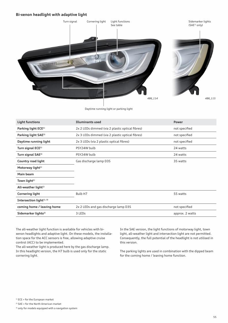
55
Bi-xenon headlight with adaptive light
Light functions
See table
Daytime running light or parking light
Cornering lightTurn signal Sidemarker lights
( SAE1) only)
486_114 486_115
Light functions Illuminants used Power
Parking light ECE1) 2x 2 LEDs dimmed (via 2 plastic optical fi bres) not specifi ed
Parking light SAE2) 2x 3 LEDs dimmed (via 2 plastic optical fi bres) not specifi ed
Daytime running light 2x 3 LEDs (via 2 plastic optical fi bres) not specifi ed
Turn signal ECE1) PSY24W bulb 24 watts
Turn signal SAE2) PSY24W bulb 24 watts
Country road light Gas discharge lamp D3S 35 watts
Motorway light1)
Main beam
Town light1)
All-weather light1)
Cornering light Bulb H7 55 watts
Intersection light1), 3)
coming home / leaving home 2x 2 LEDs and gas discharge lamp D3S not specifi ed
Sidemarker lights2) 3 LEDs approx. 2 watts
The all-weather light function is available for vehicles with bi-
xenon headlights and adaptive light. On these models, the installa-
tion space for the ACC sensors is free, allowing adaptive cruise
control (ACC) to be implemented.
The all-weather light is produced here by the gas discharge lamp.
In this headlight version, the H7 bulb is used only for the static
cornering light.
1) ECE = for the European market
2) SAE = for the North American market
3) only for models equipped with a navigation system
In the SAE version, the light functions of motorway light, town
light, all-weather light and intersection light are not permitted.
Consequently, the full potential of the headlight is not utilised in
this version.
The parking lights are used in combination with the dipped beam
for the coming home / leaving home function.
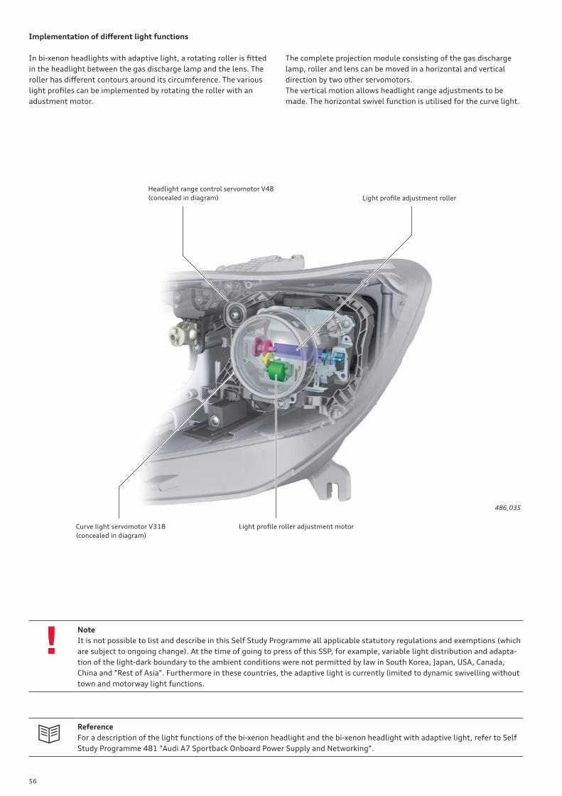
56
!
Implementation of diff erent light functions
In bi-xenon headlights with adaptive light, a rotating roller is fi tted
in the headlight between the gas discharge lamp and the lens. The
roller has diff erent contours around its circumference. The various
light profi les can be implemented by rotating the roller with an
adustment motor.
Reference
For a description of the light functions of the bi-xenon headlight and the bi-xenon headlight with adaptive light, refer to Self
Study Programme 481 "Audi A7 Sportback Onboard Power Supply and Networking".
The complete projection module consisting of the gas discharge
lamp, roller and lens can be moved in a horizontal and vertical
direction by two other servomotors.
The vertical motion allows headlight range adjustments to be
made. The horizontal swivel function is utilised for the curve light.
486_035
Light profi le roller adjustment motor
Light profi le adjustment roller
Curve light servomotor V318
(concealed in diagram)
Headlight range control servomotor V48
(concealed in diagram)
Note
It is not possible to list and describe in this Self Study Programme all applicable statutory regulations and exemptions (which
are subject to ongoing change). At the time of going to press of this SSP, for example, variable light distribution and adapta-
tion of the light-dark boundary to the ambient conditions were not permitted by law in South Korea, Japan, USA, Canada,
China and "Rest of Asia". Furthermore in these countries, the adaptive light is currently limited to dynamic swivelling without
town and motorway light functions.
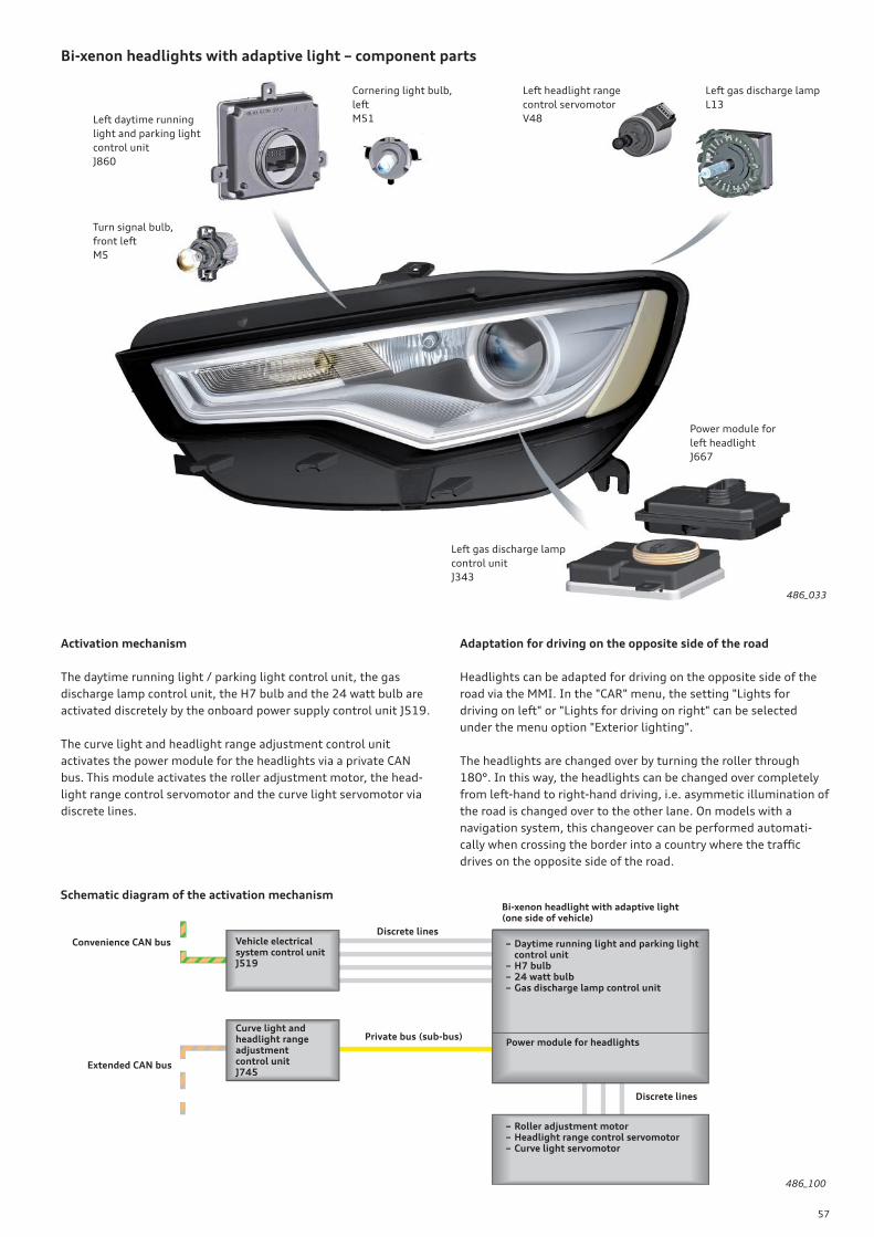
57
Bi-xenon headlights with adaptive light – component parts
Left daytime running
light and parking light
control unit
J860
Power module for
left headlight
J667
Turn signal bulb,
front left
M5
Cornering light bulb,
left
M51
Left headlight range
control servomotor
V48
Left gas discharge lamp
L13
Left gas discharge lamp
control unit
J343
486_033
Activation mechanism
The daytime running light / parking light control unit, the gas
discharge lamp control unit, the H7 bulb and the 24 watt bulb are
activated discretely by the onboard power supply control unit J519.
The curve light and headlight range adjustment control unit
activates the power module for the headlights via a private CAN
bus. This module activates the roller adjustment motor, the head-
light range control servomotor and the curve light servomotor via
discrete lines.
Adaptation for driving on the opposite side of the road
Headlights can be adapted for driving on the opposite side of the
road via the MMI. In the "CAR" menu, the setting "Lights for
driving on left" or "Lights for driving on right" can be selected
under the menu option "Exterior lighting".
The headlights are changed over by turning the roller through
180°. In this way, the headlights can be changed over completely
from left-hand to right-hand driving, i.e. asymmetic illumination of
the road is changed over to the other lane. On models with a
navigation system, this changeover can be performed automati-
cally when crossing the border into a country where the traffi c
drives on the opposite side of the road.
Schematic diagram of the activation mechanism
486_100
Bi-xenon headlight with adaptive light(one side of vehicle)
– Daytime running light and parking light control unit– H7 bulb– 24 watt bulb– Gas discharge lamp control unit
Curve light and headlight range adjustment control unitJ745
Private bus (sub-bus)
Discrete lines
Power module for headlights
– Roller adjustment motor– Headlight range control servomotor– Curve light servomotor
Discrete lines
Convenience CAN bus
Extended CAN bus
Vehicle electrical system control unitJ519
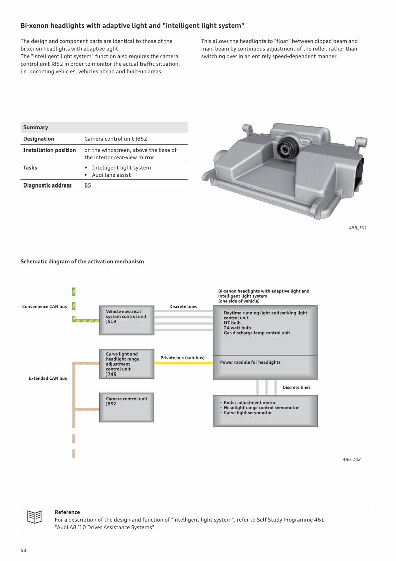
58
Bi-xenon headlights with adaptive light and "intelligent light system"
The design and component parts are identical to those of the
bi-xenon headlights with adaptive light.
The "intelligent light system" function also requires the camera
control unit J852 in order to monitor the actual traffi c situation,
i.e. oncoming vehicles, vehicles ahead and built-up areas.
This allows the headlights to "fl oat" between dipped beam and
main beam by continuous adjustment of the roller, rather than
switching over in an entirely speed-dependent manner.
Schematic diagram of the activation mechanism
486_101
486_102
Summary
Designation Camera control unit J852
Installation position on the windscreen, above the base of
the interior rear-view mirror
Tasks • Intelligent light system
• Audi lane assist
Diagnostic address 85
Reference
For a description of the design and function of "intelligent light system", refer to Self Study Programme 461
"Audi A8 ’10 Driver Assistance Systems".
– Daytime running light and parking light control unit– H7 bulb– 24 watt bulb– Gas discharge lamp control unit
Curve light and headlight range adjustment control unitJ745
Private bus (sub-bus)
Discrete lines
Power module for headlights
– Roller adjustment motor– Headlight range control servomotor– Curve light servomotor
Discrete lines
Camera control unitJ852
Convenience CAN bus
Extended CAN bus
Vehicle electrical system control unitJ519
Bi-xenon headlights with adaptive light andintelligent light system(one side of vehicle)
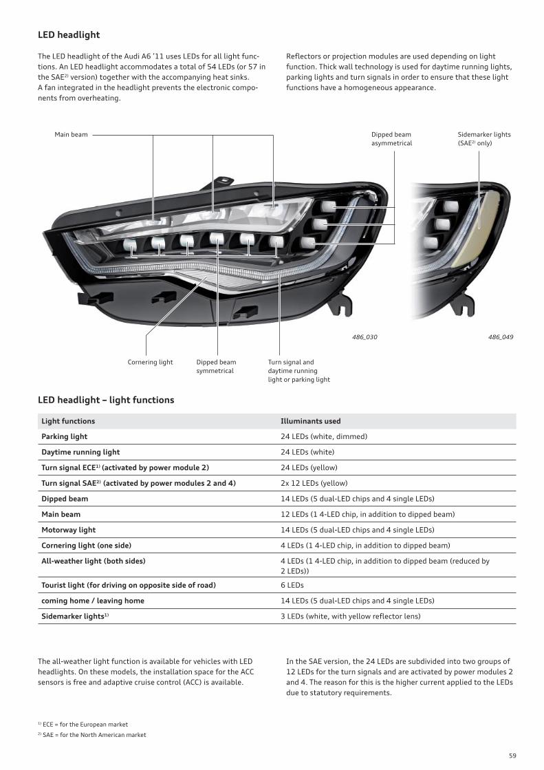
59
LED headlight
The LED headlight of the Audi A6 ’11 uses LEDs for all light func-
tions. An LED headlight accommodates a total of 54 LEDs (or 57 in
the SAE2) version) together with the accompanying heat sinks.
A fan integrated in the headlight prevents the electronic compo-
nents from overheating.
Turn signal and
daytime running
light or parking light
Main beam Dipped beam
asymmetrical
Cornering light
Light functions Illuminants used
Parking light 24 LEDs (white, dimmed)
Daytime running light 24 LEDs (white)
Turn signal ECE1) (activated by power module 2) 24 LEDs (yellow)
Turn signal SAE2) (activated by power modules 2 and 4) 2x 12 LEDs (yellow)
Dipped beam 14 LEDs (5 dual-LED chips and 4 single LEDs)
Main beam 12 LEDs (1 4-LED chip, in addition to dipped beam)
Motorway light 14 LEDs (5 dual-LED chips and 4 single LEDs)
Cornering light (one side) 4 LEDs (1 4-LED chip, in addition to dipped beam)
All-weather light (both sides) 4 LEDs (1 4-LED chip, in addition to dipped beam (reduced by
2 LEDs))
Tourist light (for driving on opposite side of road) 6 LEDs
coming home / leaving home 14 LEDs (5 dual-LED chips and 4 single LEDs)
Sidemarker lights1) 3 LEDs (white, with yellow refl ector lens)
486_030 486_049
Dipped beam
symmetrical
Sidemarker lights
( SAE2) only)
1) ECE = for the European market
2) SAE = for the North American market
LED headlight – light functions
Refl ectors or projection modules are used depending on light
function. Thick wall technology is used for daytime running lights,
parking lights and turn signals in order to ensure that these light
functions have a homogeneous appearance.
The all-weather light function is available for vehicles with LED
headlights. On these models, the installation space for the ACC
sensors is free and adaptive cruise control (ACC) is available.
In the SAE version, the 24 LEDs are subdivided into two groups of
12 LEDs for the turn signals and are activated by power modules 2
and 4. The reason for this is the higher current applied to the LEDs
due to statutory requirements.
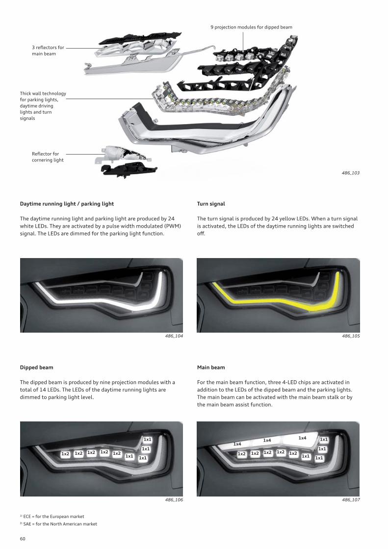
60
Daytime running light / parking light
The daytime running light and parking light are produced by 24
white LEDs. They are activated by a pulse width modulated (PWM)
signal. The LEDs are dimmed for the parking light function.
Dipped beam
The dipped beam is produced by nine projection modules with a
total of 14 LEDs. The LEDs of the daytime running lights are
dimmed to parking light level.
Turn signal
The turn signal is produced by 24 yellow LEDs. When a turn signal
is activated, the LEDs of the daytime running lights are switched
off .
Main beam
For the main beam function, three 4-LED chips are activated in
addition to the LEDs of the dipped beam and the parking lights.
The main beam can be activated with the main beam stalk or by
the main beam assist function.
486_104
486_106 486_107
486_105
486_103
Refl ector for
cornering light
Thick wall technology
for parking lights,
daytime driving
lights and turn
signals
9 projection modules for dipped beam
3 refl ectors for
main beam
1) ECE = for the European market
2) SAE = for the North American market
1x2 1x2 1x21x21x2
1x1
1x1
1x1
1x11x2 1x2 1x21x21x2
1x1
1x1
1x1
1x1
1x41x4
1x4
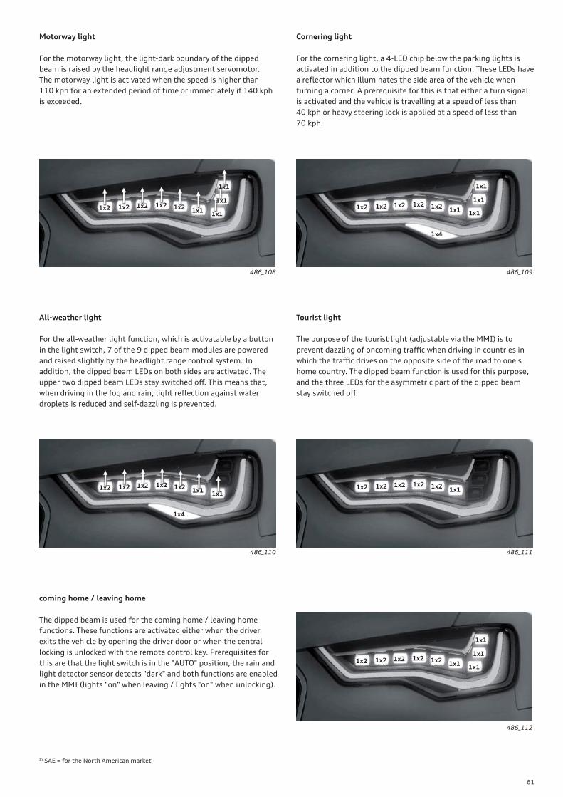
61
All-weather light
For the all-weather light function, which is activatable by a button
in the light switch, 7 of the 9 dipped beam modules are powered
and raised slightly by the headlight range control system. In
addition, the dipped beam LEDs on both sides are activated. The
upper two dipped beam LEDs stay switched off . This means that,
when driving in the fog and rain, light refl ection against water
droplets is reduced and self-dazzling is prevented.
Tourist light
The purpose of the tourist light (adjustable via the MMI) is to
prevent dazzling of oncoming traffi c when driving in countries in
which the traffi c drives on the opposite side of the road to one's
home country. The dipped beam function is used for this purpose,
and the three LEDs for the asymmetric part of the dipped beam
stay switched off .
coming home / leaving home
The dipped beam is used for the coming home / leaving home
functions. These functions are activated either when the driver
exits the vehicle by opening the driver door or when the central
locking is unlocked with the remote control key. Prerequisites for
this are that the light switch is in the "AUTO" position, the rain and
light detector sensor detects "dark" and both functions are enabled
in the MMI (lights "on" when leaving / lights "on" when unlocking).
Motorway light
For the motorway light, the light-dark boundary of the dipped
beam is raised by the headlight range adjustment servomotor.
The motorway light is activated when the speed is higher than
110 kph for an extended period of time or immediately if 140 kph
is exceeded.
Cornering light
For the cornering light, a 4-LED chip below the parking lights is
activated in addition to the dipped beam function. These LEDs have
a refl ector which illuminates the side area of the vehicle when
turning a corner. A prerequisite for this is that either a turn signal
is activated and the vehicle is travelling at a speed of less than
40 kph or heavy steering lock is applied at a speed of less than
70 kph.
486_109486_108
486_110 486_111
486_112
2) SAE = for the North American market
1x2 1x2 1x21x21x2
1x1
1x1
1x1
1x11x2 1x2 1x21x21x2
1x1
1x1
1x1
1x1
1x2 1x2 1x21x21x2
1x11x1
1x2 1x2 1x21x21x21x1
1x4
1x4
1x2 1x2 1x21x21x2
1x1
1x1
1x1
1x1
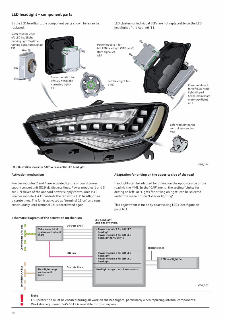
62
!
LED headlight – component parts
In the LED headlight, the component parts shown here can be
replaced.
Left headlight fan
V407
Power module 3 for
left LED headlight
(cornering light)
A33
Power module 2 for
left LED headlight
(parking light/daytime
running light, turn signal)
A32
Power module 4 for
left LED headlight (SAE only2))
(turn signal 2)
A34
486_034
Left headlight range
control servomotor
V48
LED clusters or individual LEDs are not replaceable on the LED
headlight of the Audi A6 ’11.
Activation mechanism
Powder modules 2 and 4 are activated by the onboard power
supply control unit J519 via discrete lines. Power modules 1 and 3
are LIN slaves of the onboard power supply control unit J519.
Powder module 1 A31 controls the fan in the LED headlight via
discrete lines. The fan is activated at "terminal 15 on" and runs
continuously until terminal 15 is deactivated again.
Adaptation for driving on the opposite side of the road
Headlights can be adapted for driving on the opposite side of the
road via the MMI. In the "CAR" menu, the setting "Lights for
driving on left" or "Lights for driving on right" can be selected
under the menu option "Exterior lighting".
This adjustment is made by deactivating LEDs (see fi gure on
page 61).
The illustration shows the SAE2) version of the LED headlight
Power module 1
for left LED head-
light (dipped
beam, main beam,
motorway light)
A31
Schematic diagram of the activation mechanismLED headlight(one side of vehicle)
Vehicle electrical system control unitJ519
– Power module 2 for left LED headlight– Power module 4 for left LED headlight (SAE only2))
Discrete lines
– Power module 3 for left LED headlight– Power module 1 for left LED headlight
486_113
LED headlight fan
LIN bus
Discrete lines
Co
nv
en
ien
ce C
AN
bu
s
Headlight range control servomotorDiscrete lines
Headlight range control unitJ431
Ex
ten
de
d C
AN
bu
s
Note
ESD protection must be ensured during all work on the headlights, particularly when replacing internal components.
Workshop equipment VAS 6613 is available for this purpose.
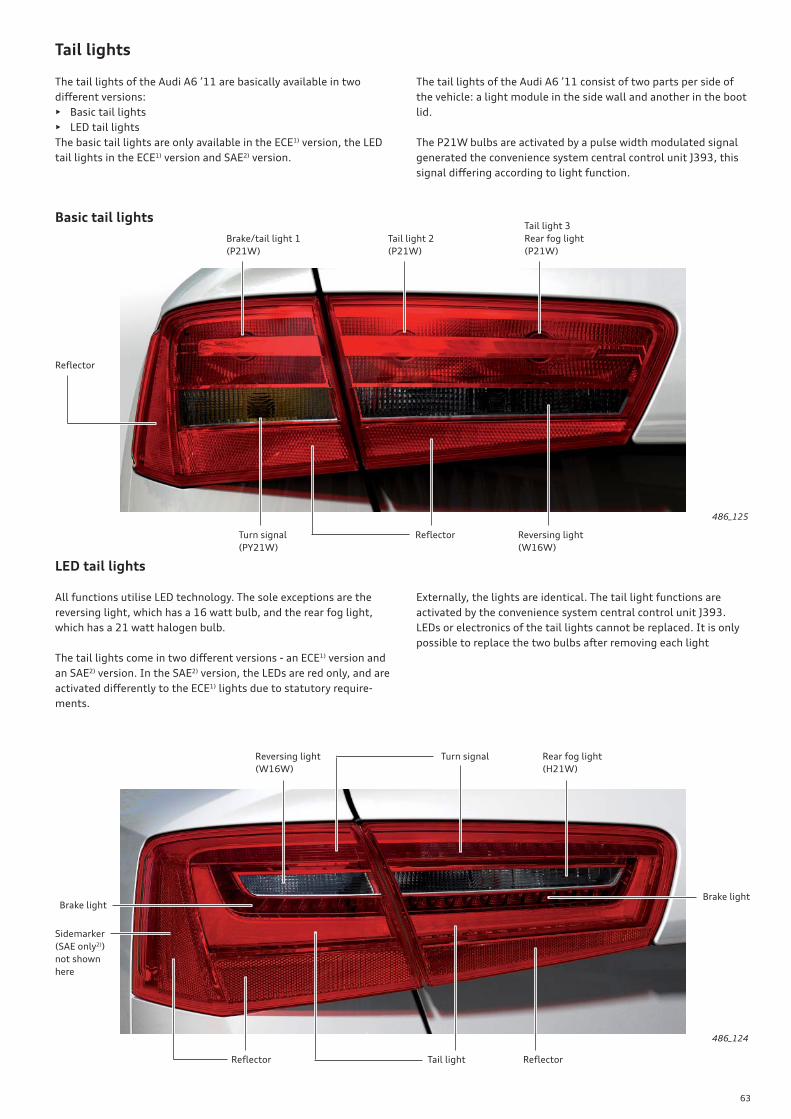
63
LED tail lights
486_124
Tail lights
The tail lights of the Audi A6 ’11 are basically available in two
diff erent versions:
• Basic tail lights
• LED tail lights
The basic tail lights are only available in the ECE1) version, the LED
tail lights in the ECE1) version and SAE2) version.
The tail lights of the Audi A6 ’11 consist of two parts per side of
the vehicle: a light module in the side wall and another in the boot
lid.
The P21W bulbs are activated by a pulse width modulated signal
generated the convenience system central control unit J393, this
signal diff ering according to light function.
All functions utilise LED technology. The sole exceptions are the
reversing light, which has a 16 watt bulb, and the rear fog light,
which has a 21 watt halogen bulb.
The tail lights come in two diff erent versions - an ECE1) version and
an SAE2) version. In the SAE2) version, the LEDs are red only, and are
activated diff erently to the ECE1) lights due to statutory require-
ments.
Externally, the lights are identical. The tail light functions are
activated by the convenience system central control unit J393.
LEDs or electronics of the tail lights cannot be replaced. It is only
possible to replace the two bulbs after removing each light
Basic tail lights
486_125
Brake/tail light 1
(P21W)
Tail light 2
(P21W)
Tail light 3
Rear fog light
(P21W)
Refl ector
Turn signal
(PY21W)
Reversing light
(W16W)
Refl ector
Brake lightBrake light
Rear fog light
(H21W)
Reversing light
(W16W)
Refl ector
Turn signal
Tail light Refl ector
Sidemarker
(SAE only2))
not shown
here
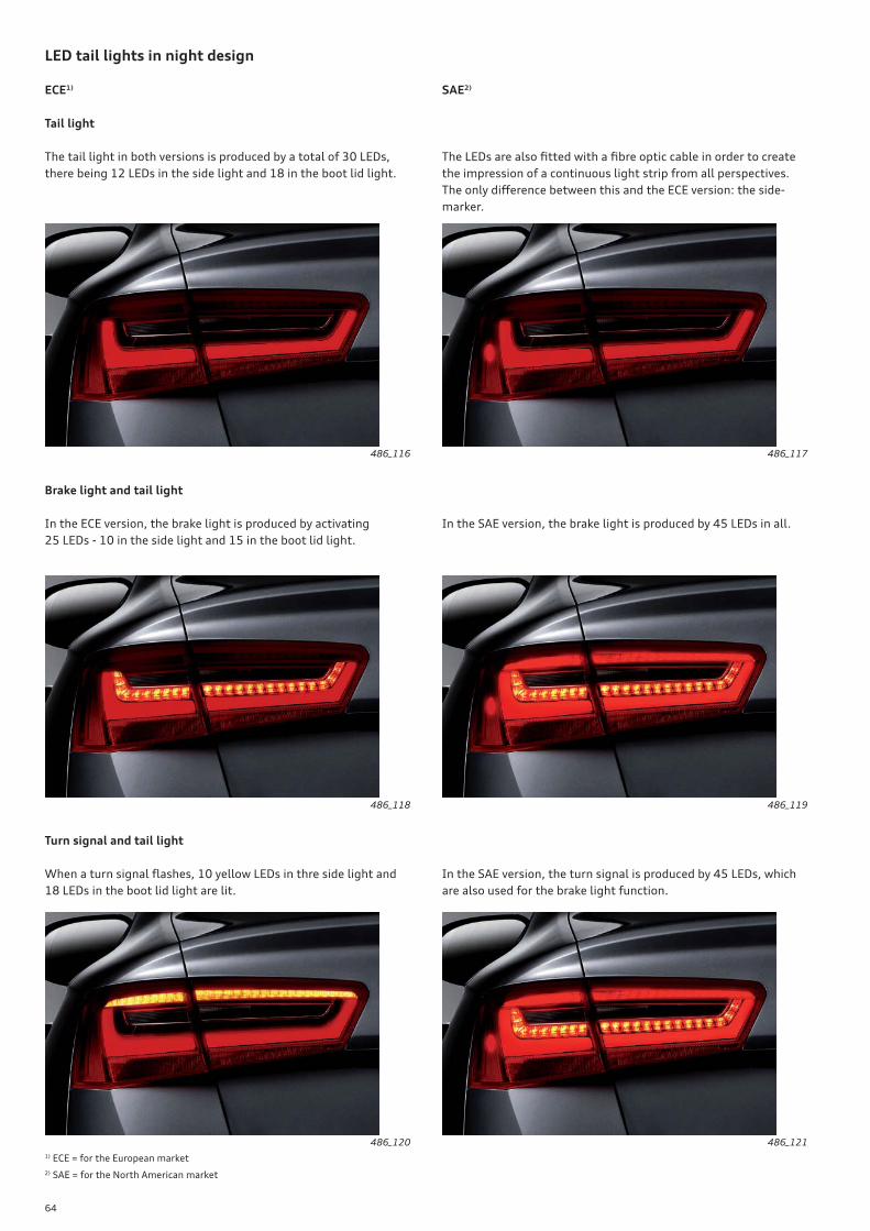
64
LED tail lights in night design
ECE1) SAE2)
1) ECE = for the European market
2) SAE = for the North American market
Turn signal and tail light
When a turn signal fl ashes, 10 yellow LEDs in thre side light and
18 LEDs in the boot lid light are lit.
Tail light
The tail light in both versions is produced by a total of 30 LEDs,
there being 12 LEDs in the side light and 18 in the boot lid light.
The LEDs are also fi tted with a fi bre optic cable in order to create
the impression of a continuous light strip from all perspectives.
The only diff erence between this and the ECE version: the side-
marker.
Brake light and tail light
In the ECE version, the brake light is produced by activating
25 LEDs - 10 in the side light and 15 in the boot lid light.
In the SAE version, the brake light is produced by 45 LEDs in all.
In the SAE version, the turn signal is produced by 45 LEDs, which
are also used for the brake light function.
486_116 486_117
486_118 486_119
486_120 486_121
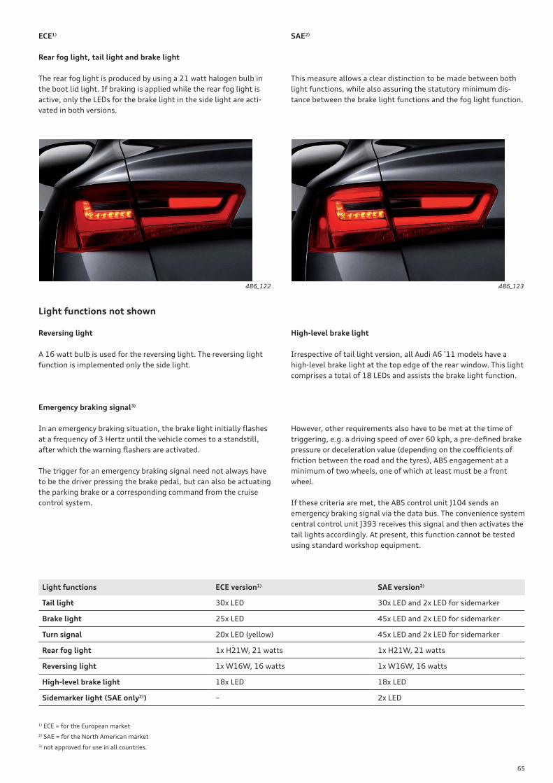
65
ECE1) SAE2)
1) ECE = for the European market
2) SAE = for the North American market
3) not approved for use in all countries.
Rear fog light, tail light and brake light
The rear fog light is produced by using a 21 watt halogen bulb in
the boot lid light. If braking is applied while the rear fog light is
active, only the LEDs for the brake light in the side light are acti-
vated in both versions.
This measure allows a clear distinction to be made between both
light functions, while also assuring the statutory minimum dis-
tance between the brake light functions and the fog light function.
486_122 486_123
Light functions ECE version1) SAE version2)
Tail light 30x LED 30x LED and 2x LED for sidemarker
Brake light 25x LED 45x LED and 2x LED for sidemarker
Turn signal 20x LED (yellow) 45x LED and 2x LED for sidemarker
Rear fog light 1x H21W, 21 watts 1x H21W, 21 watts
Reversing light 1x W16W, 16 watts 1x W16W, 16 watts
High-level brake light 18x LED 18x LED
Sidemarker light (SAE only2)) – 2x LED
Emergency braking signal3)
In an emergency braking situation, the brake light initially fl ashes
at a frequency of 3 Hertz until the vehicle comes to a standstill,
after which the warning fl ashers are activated.
The trigger for an emergency braking signal need not always have
to be the driver pressing the brake pedal, but can also be actuating
the parking brake or a corresponding command from the cruise
control system.
However, other requirements also have to be met at the time of
triggering, e.g. a driving speed of over 60 kph, a pre-defi ned brake
pressure or deceleration value (depending on the coeffi cients of
friction between the road and the tyres), ABS engagement at a
minimum of two wheels, one of which at least must be a front
wheel.
If these criteria are met, the ABS control unit J104 sends an
emergency braking signal via the data bus. The convenience system
central control unit J393 receives this signal and then activates the
tail lights accordingly. At present, this function cannot be tested
using standard workshop equipment.
Reversing light
A 16 watt bulb is used for the reversing light. The reversing light
function is implemented only the side light.
High-level brake light
Irrespective of tail light version, all Audi A6 ’11 models have a
high-level brake light at the top edge of the rear window. This light
comprises a total of 18 LEDs and assists the brake light function.
Light functions not shown
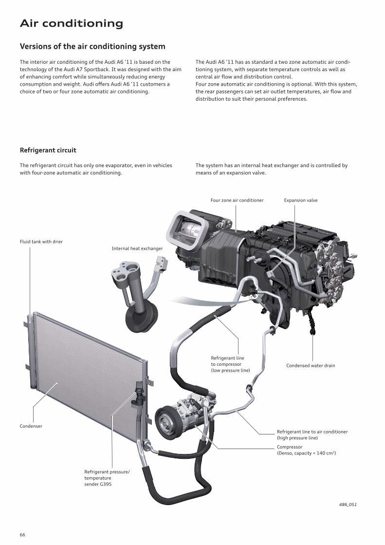
66
Versions of the air conditioning system
The interior air conditioning of the Audi A6 ’11 is based on the
technology of the Audi A7 Sportback. It was designed with the aim
of enhancing comfort while simultaneously reducing energy
consumption and weight. Audi off ers Audi A6 ’11 customers a
choice of two or four zone automatic air conditioning.
The Audi A6 ’11 has as standard a two zone automatic air condi-
tioning system, with separate temperature controls as well as
central air fl ow and distribution control.
Four zone automatic air conditioning is optional. With this system,
the rear passengers can set air outlet temperatures, air fl ow and
distribution to suit their personal preferences.
Refrigerant circuit
The refrigerant circuit has only one evaporator, even in vehicles
with four-zone automatic air conditioning.
The system has an internal heat exchanger and is controlled by
means of an expansion valve.
486_051
Fluid tank with drier
Refrigerant line
to compressor
(low pressure line)
Condenser
Refrigerant pressure/
temperature
sender G395
Refrigerant line to air conditioner
(high pressure line)
Compressor
(Denso, capacity = 140 cm3)
Condensed water drain
Internal heat exchanger
Four zone air conditioner Expansion valve
Air conditioning
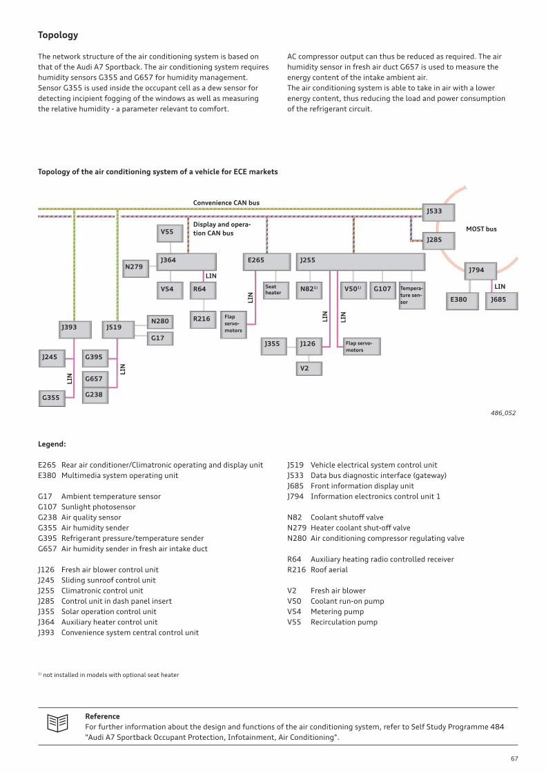
67
Reference
For further information about the design and functions of the air conditioning system, refer to Self Study Programme 484
"Audi A7 Sportback Occupant Protection, Infotainment, Air Conditioning".
Topology
The network structure of the air conditioning system is based on
that of the Audi A7 Sportback. The air conditioning system requires
humidity sensors G355 and G657 for humidity management.
Sensor G355 is used inside the occupant cell as a dew sensor for
detecting incipient fogging of the windows as well as measuring
the relative humidity - a parameter relevant to comfort.
AC compressor output can thus be reduced as required. The air
humidity sensor in fresh air duct G657 is used to measure the
energy content of the intake ambient air.
The air conditioning system is able to take in air with a lower
energy content, thus reducing the load and power consumption
of the refrigerant circuit.
486_052
J393 J519
J245
G355
G395
G657
G238
N280
G17
J364N279
V54 R64
R216 Flap
servo-
motors
E265
Seat heater
J255
N821) V501) G107 Tempera-
ture sen-
sor
J355 J126
V2
Flap servo-
motors
E380
J794
J685
J285
J533
Legend:
E265 Rear air conditioner/Climatronic operating and display unit
E380 Multimedia system operating unit
G17 Ambient temperature sensor
G107 Sunlight photosensor
G238 Air quality sensor
G355 Air humidity sender
G395 Refrigerant pressure/temperature sender
G657 Air humidity sender in fresh air intake duct
J126 Fresh air blower control unit
J245 Sliding sunroof control unit
J255 Climatronic control unit
J285 Control unit in dash panel insert
J355 Solar operation control unit
J364 Auxiliary heater control unit
J393 Convenience system central control unit
Convenience CAN bus
Display and opera-
tion CAN busMOST bus
J519 Vehicle electrical system control unit
J533 Data bus diagnostic interface (gateway)
J685 Front information display unit
J794 Information electronics control unit 1
N82 Coolant shutoff valve
N279 Heater coolant shut-off valve
N280 Air conditioning compressor regulating valve
R64 Auxiliary heating radio controlled receiver
R216 Roof aerial
V2 Fresh air blower
V50 Coolant run-on pump
V54 Metering pump
V55 Recirculation pump
LIN
LIN
LIN
LIN
LIN
LIN
LIN
1) not installed in models with optional seat heater
V55
Topology of the air conditioning system of a vehicle for ECE markets

68
!Note
In effi ciency mode, the customer might experience a reduction in comfort. For example, the AC compressor or the supple-
mentary heater may be deactivated with the result that the interior cannot be optimally air conditioned in all ambient
conditions.
Eff ects of AC settings when effi ciency mode is activated
Default settings
at low temperatures
AC mode "eco" Default settings
at high temperatures
• Supplementary heater activated
• Compressor deactivated
• The functional range of the start-stop
system is limited by the air conditioning
system
• Supplementary heater may be inactive
• Compressor may be inactive
• The functional range of the start-stop
system is limited by the air conditioning
system (longer stop phases)
• Supplementary heater deactivated
• Compressor activated
• The functional range of the start-stop
system is limited by the air conditioning
system
effi ciency mode
In the Audi A6 ’11, the customer can select the effi ciency mode in
the MMI via Audi drive select. The air conditioning system is then
confi gured for optimal fuel economy. In effi ciency mode, the AC
mode "eco" is automatically activated.
When the AC mode "eco" is activated, the air conditioning system
switches over to an energy-optimised operating range within
temperature thresholds compatible with the occupants. The air
conditioning system operates at a reduced level.
Within the temperature range from approx. –5 °C to +20 °C, the
system attempts to set the interior climate desired by the occu-
pant without the supplementary heater or with reduced additional
heating and/or with low compressor output, or with the compres-
sor entirely switched off .
Deselecting the AC mode "eco"
If desired, the customer can change the AC mode via the MMI (see
fi gure on right). If the customer exits the automatically activated
AC mode "eco" in effi ciency mode, the air conditioning system is
reconfi gured for optimal comfort and thus leaves the consump-
tion-optimised state.
The AC modes can be implemented diff erently depending on
country.
Eff ects on the air conditioning system
• Switching to the AC mode "eco"
• AC compressor and supplementary heater is set to reduced
output or deactivated if the ambient conditions permit (for
example, at a moderate ambient temperature of +15 °C and a
relativie humidity level of 30 %)
• When the engine is shut off by the start-stop system, the limits
for the permissible air outlet and interior temperature values
(comfort) are extended so that the engine starts later, resulting
in longer stop phases and potentially higher fuel economy.
• The Innovative Thermal Management (ITM) system primarily
controls heating of the gearbox (and therefore, secondarily,
heating of the vehicle interior)
Limits of consumption-optimised AC operation
Limits are all driving situations in which driving safety is poten-
tially limited or manual deselection of the AC mode "eco" by the
driver. Examples of these situations are:
• Imminent windscreen fogging when it starts to rain
(relative humidity is near 100 %)
• Activation of Defrost mode by the driver
• Deselection of the AC mode "eco": when the driver switches to
either "medium" or "intensive" mode, the AC system leaves the
energy-optimised operating range even if the effi ciency mode
stays activated ("effi ciency" in Audi drive select)
486_053
Air conditioningCar
Systems
eco
medium
intensive
AC mode
Suppl. heater
Set indiv.
Temperature
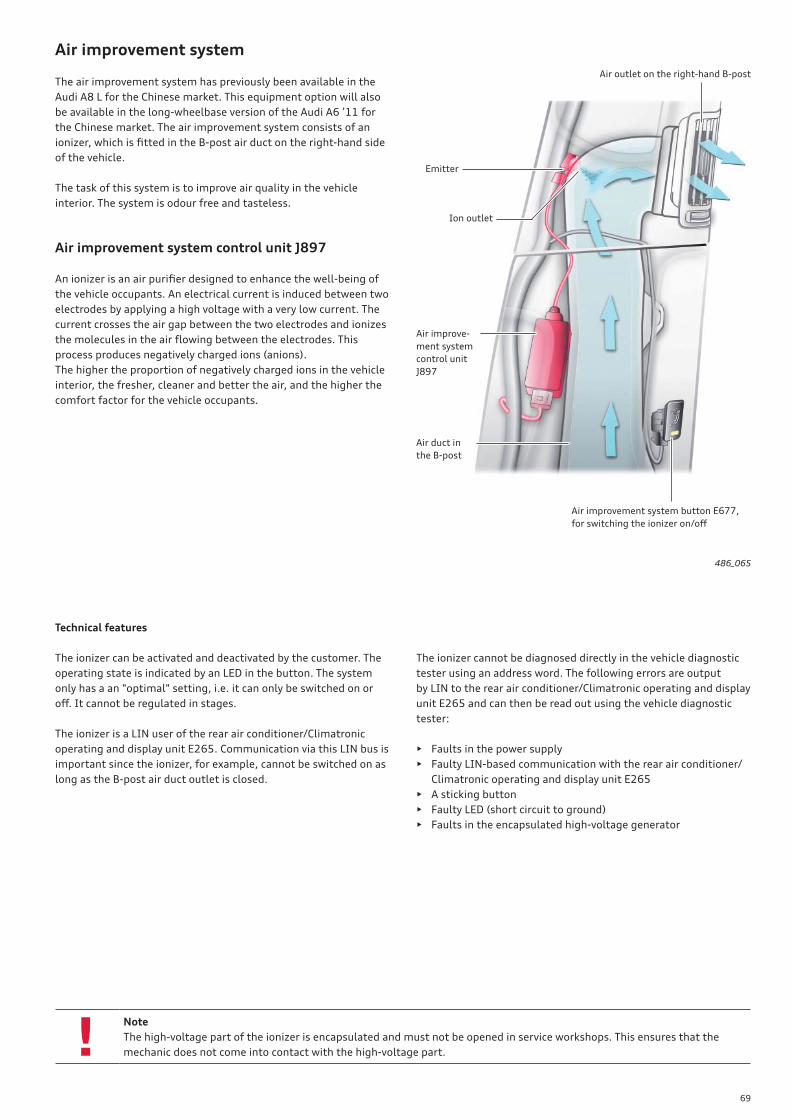
69
!
Air improvement system
The air improvement system has previously been available in the
Audi A8 L for the Chinese market. This equipment option will also
be available in the long-wheelbase version of the Audi A6 ’11 for
the Chinese market. The air improvement system consists of an
ionizer, which is fi tted in the B-post air duct on the right-hand side
of the vehicle.
The task of this system is to improve air quality in the vehicle
interior. The system is odour free and tasteless.
Air improvement system control unit J897
An ionizer is an air purifi er designed to enhance the well-being of
the vehicle occupants. An electrical current is induced between two
electrodes by applying a high voltage with a very low current. The
current crosses the air gap between the two electrodes and ionizes
the molecules in the air fl owing between the electrodes. This
process produces negatively charged ions (anions).
The higher the proportion of negatively charged ions in the vehicle
interior, the fresher, cleaner and better the air, and the higher the
comfort factor for the vehicle occupants.
Technical features
The ionizer can be activated and deactivated by the customer. The
operating state is indicated by an LED in the button. The system
only has a an "optimal" setting, i.e. it can only be switched on or
off . It cannot be regulated in stages.
The ionizer is a LIN user of the rear air conditioner/Climatronic
operating and display unit E265. Communication via this LIN bus is
important since the ionizer, for example, cannot be switched on as
long as the B-post air duct outlet is closed.
The ionizer cannot be diagnosed directly in the vehicle diagnostic
tester using an address word. The following errors are output
by LIN to the rear air conditioner/Climatronic operating and display
unit E265 and can then be read out using the vehicle diagnostic
tester:
• Faults in the power supply
• Faulty LIN-based communication with the rear air conditioner/
Climatronic operating and display unit E265
• A sticking button
• Faulty LED (short circuit to ground)
• Faults in the encapsulated high-voltage generator
Note
The high-voltage part of the ionizer is encapsulated and must not be opened in service workshops. This ensures that the
mechanic does not come into contact with the high-voltage part.
486_065
Emitter
Air improve-
ment system
control unit
J897
Air duct in
the B-post
Air improvement system button E677,
for switching the ionizer on/off
Air outlet on the right-hand B-post
Ion outlet
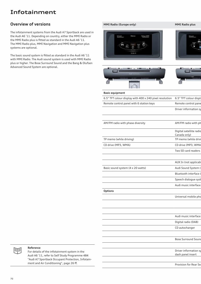
70
Reference
For details of the infotainment system in the
Audi A6 ’11, refer to Self Study Programme 484
"Audi A7 Sportback Occupant Protection, Infotain-
ment and Air Conditioning", page 26 ff .
Overview of versions
The infotainment systems from the Audi A7 Sportback are used in
the Audi A6 ’11. Depending on country, either the MMI Radio or
the MMI Radio plus is fi tted as standard in the Audi A6 ’11.
The MMI Radio plus, MMI Navigation and MMI Navigation plus
systems are optional.
The basic sound system is fi tted as standard in the Audi A6 ’11
with MMI Radio. The Audi sound system is used with MMI Radio
plus or higher. The Bose Surround Sound and the Bang & Olufsen
Advanced Sound System are optional.
MMI Radio (Europe only) MMI Radio plus
Basic equipment
6.5“ TFT colour display with 400 x 240 pixel resolution 6.5“ TFT colour displa
Remote control panel with 6 station keys Remote control pane
Driver information sy
AM/FM radio with phase diversity AM/FM radio with ph
Digital satellite radio
Canada only)
TP memo (while driving) TP memo (while drivi
CD drive (MP3, WMA) CD drive (MP3, WMA,
Two SD card readers
AUX In (not applicabl
Basic sound system (4 x 20 watts) Audi Sound System (1
Bluetooth interface (
Speech dialogue syst
Audi music interface
Options
Universal mobile pho
Audi music interface
Digital radio (DAB)
CD autochanger
Bose Surround Sound
Driver information sy
dash panel insert
Provision for Rear Sea
Infotainment
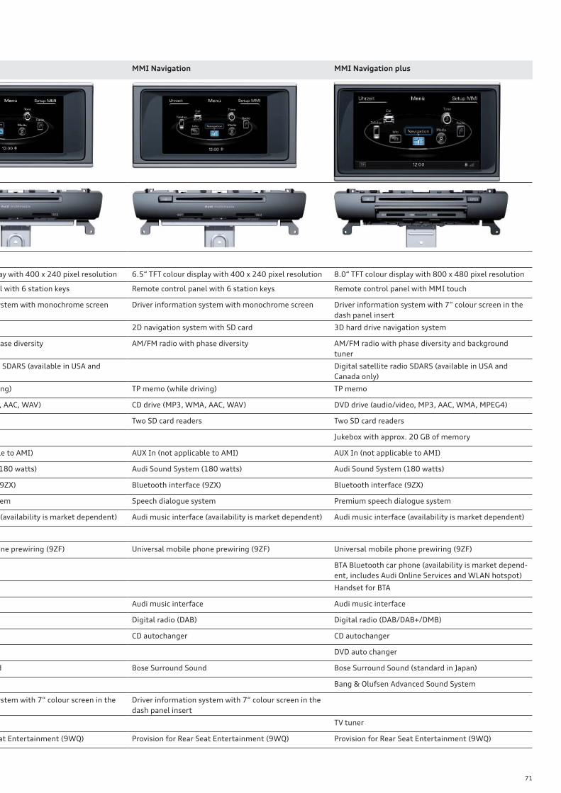
71
MMI Navigation MMI Navigation plus
ay with 400 x 240 pixel resolution 6.5“ TFT colour display with 400 x 240 pixel resolution 8.0“ TFT colour display with 800 x 480 pixel resolution
l with 6 station keys Remote control panel with 6 station keys Remote control panel with MMI touch
ystem with monochrome screen Driver information system with monochrome screen Driver information system with 7“ colour screen in the
dash panel insert
2D navigation system with SD card 3D hard drive navigation system
ase diversity AM/FM radio with phase diversity AM/FM radio with phase diversity and background
tuner
SDARS (available in USA and Digital satellite radio SDARS (available in USA and
Canada only)
ng) TP memo (while driving) TP memo
, AAC, WAV) CD drive (MP3, WMA, AAC, WAV) DVD drive (audio/video, MP3, AAC, WMA, MPEG4)
Two SD card readers Two SD card readers
Jukebox with approx. 20 GB of memory
le to AMI) AUX In (not applicable to AMI) AUX In (not applicable to AMI)
180 watts) Audi Sound System (180 watts) Audi Sound System (180 watts)
9ZX) Bluetooth interface (9ZX) Bluetooth interface (9ZX)
em Speech dialogue system Premium speech dialogue system
(availability is market dependent) Audi music interface (availability is market dependent) Audi music interface (availability is market dependent)
one prewiring (9ZF) Universal mobile phone prewiring (9ZF) Universal mobile phone prewiring (9ZF)
BTA Bluetooth car phone (availability is market depend-
ent, includes Audi Online Services and WLAN hotspot)
Handset for BTA
Audi music interface Audi music interface
Digital radio (DAB) Digital radio (DAB/DAB+/DMB)
CD autochanger CD autochanger
DVD auto changer
d Bose Surround Sound Bose Surround Sound (standard in Japan)
Bang & Olufsen Advanced Sound System
ystem with 7“ colour screen in the Driver information system with 7“ colour screen in the
dash panel insert
TV tuner
at Entertainment (9WQ) Provision for Rear Seat Entertainment (9WQ) Provision for Rear Seat Entertainment (9WQ)
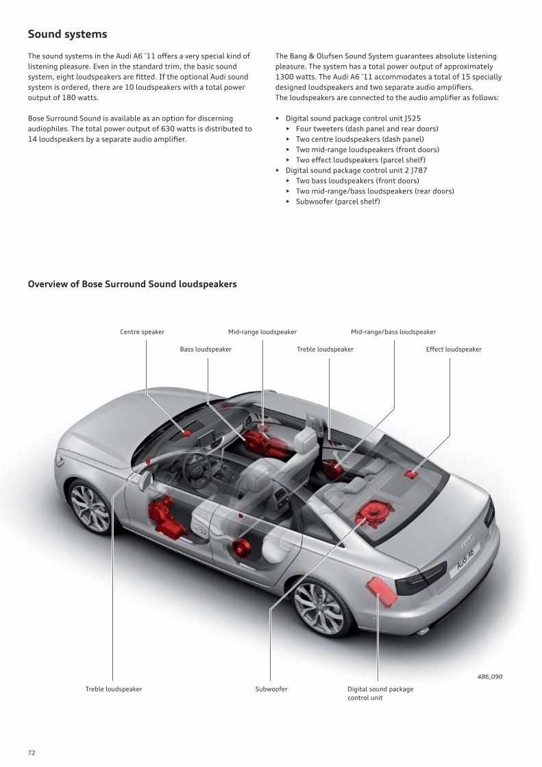
72
Sound systems
The sound systems in the Audi A6 ’11 off ers a very special kind of
listening pleasure. Even in the standard trim, the basic sound
system, eight loudspeakers are fi tted. If the optional Audi sound
system is ordered, there are 10 loudspeakers with a total power
output of 180 watts.
Bose Surround Sound is available as an option for discerning
audiophiles. The total power output of 630 watts is distributed to
14 loudspeakers by a separate audio amplifi er.
The Bang & Olufsen Sound System guarantees absolute listening
pleasure. The system has a total power output of approximately
1300 watts. The Audi A6 ’11 accommodates a total of 15 specially
designed loudspeakers and two separate audio amplifi ers.
The loudspeakers are connected to the audio amplifi er as follows:
• Digital sound package control unit J525
• Four tweeters (dash panel and rear doors)
• Two centre loudspeakers (dash panel)
• Two mid-range loudspeakers (front doors)
• Two eff ect loudspeakers (parcel shelf)
• Digital sound package control unit 2 J787
• Two bass loudspeakers (front doors)
• Two mid-range/bass loudspeakers (rear doors)
• Subwoofer (parcel shelf)
Overview of Bose Surround Sound loudspeakers
486_090
Centre speaker Mid-range loudspeaker
Treble loudspeaker
Treble loudspeaker Eff ect loudspeakerBass loudspeaker
Mid-range/bass loudspeaker
Subwoofer Digital sound package
control unit
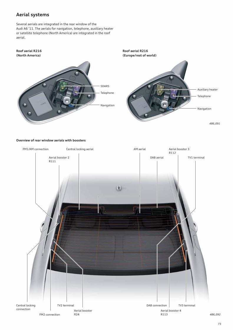
73
Aerial systems
Several aerials are integrated in the rear window of the
Audi A6 ’11. The aerials for navigation, telephone, auxiliary heater
or satellite telephone (North America) are integrated in the roof
aerial.
Roof aerial R216
(North America)
Roof aerial R216
(Europe/rest of world)
486_091
SDARS
Telephone
Navigation
Auxiliary heater
Telephone
Navigation
Overview of rear window aerials with boosters
486_092
TV2 terminal
DAB aerial
Aerial booster 4
R113
TV3 terminal
Aerial booster 2
R111
AM aerialFM1/AM connection
Central locking
connectionAerial booster
R24FM2 connection
Aerial booster 3
R112
TV1 terminal
DAB connection
Central locking aerial
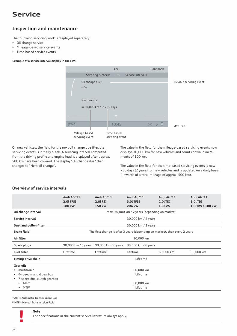
74
!Note
The specifi cations in the current service literature always apply.
Inspection and maintenance
The value in the fi eld for the mileage-based servicing events now
displays 30,000 km for new vehicles and counts down in incre-
ments of 100 km.
The value in the fi eld for the time-based servicing events is now
730 days (2 years) for new vehicles and is updated on a daily basis
(upwards of a total mileage of approx. 500 km).
On new vehicles, the fi eld for the next oil change due (fl exible
servicing event) is initially blank. A servicing interval computed
from the driving profi le and engine load is displayed after approx.
500 km have been covered. The display "Oil change due" then
changes to "Next oil change".
Overview of service intervals
Audi A6 ’11
2.0l TFSI
180 kW
Audi A6 ’11
2.8l FSI
150 kW
Audi A6 ’11
3.0l TFSI
204 kW
Audi A6 ’11
2.0l TDI
130 kW
Audi A6 ’11
3.0l TDI
150 kW / 180 kW
Oil change interval max. 30,000 km / 2 years (depending on market)
Service interval 30,000 km / 2 years
Dust and pollen fi lter 30,000 km / 2 years
Brake fl uid The fi rst change is after 3 years (depending on market), then every 2 years
Air fi lter 90,000 km
Spark plugs 90,000 km / 6 years 90,000 km / 6 years 90,000 km / 6 years
Fuel fi lter Lifetime Lifetime Lifetime 60,000 km 60,000 km
Timing drive chain Lifetime
Gear oils
• multitronic
• 6-speed manual gearbox
• 7-speed dual clutch gearbox
• ATF1)
• MTF2)
60,000 km
Lifetime
60,000 km
Lifetime
1) ATF = Automatic Transmission Fluid
2) MTF = Manual Transmission Fluid
The following servicing work is displayed separately:
• Oil change service
• Mileage-based service events
• Time-based service events
Oil change due:
--/--
Next service:
in 30,000 km / in 730 days
Service intervalsServicing & checks
HandbookCar
486_126
Mileage-based
servicing event
Time-based
servicing event
Example of a service interval display in the MMI
Flexible servicing event
Service
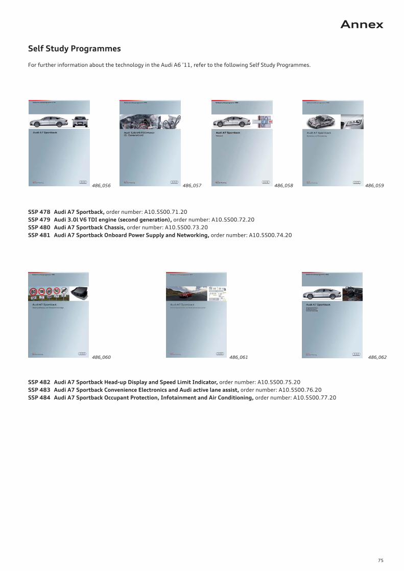
75
Self Study Programmes
For further information about the technology in the Audi A6 ’11, refer to the following Self Study Programmes.
SSP 478 Audi A7 Sportback, order number: A10.5S00.71.20
SSP 479 Audi 3.0l V6 TDI engine (second generation), order number: A10.5S00.72.20
SSP 480 Audi A7 Sportback Chassis, order number: A10.5S00.73.20
SSP 481 Audi A7 Sportback Onboard Power Supply and Networking, order number: A10.5S00.74.20
486_056
SSP 482 Audi A7 Sportback Head-up Display and Speed Limit Indicator, order number: A10.5S00.75.20
SSP 483 Audi A7 Sportback Convenience Electronics and Audi active lane assist, order number: A10.5S00.76.20
SSP 484 Audi A7 Sportback Occupant Protection, Infotainment and Air Conditioning, order number: A10.5S00.77.20
486_059486_057
486_060 486_062486_061
486_058
Annex

Audi
Audi
Vorsprung durch Technik
Service Training
48
6
Audi A6 ’11
All rights reserved.
Technical specifi cations are subject to
change.
Copyright
AUDI AG
I/VK-35
AUDI AG
D-85045 Ingolstadt
Technical status 02/11
Printed in Germany
A11.5S00.80.20
Self Study Programme 486


