
EOARD Materials & NanotechAFOSR Spring Review
18 March 2011
Lt Col Randall ‘Ty’ Pollak
Program Manager
AFOSR/EOARD
Air Force Office of Scientific Research
AFOSR
Distribution A: Approved for public release; distribution is unlimited. 88ABW-2011-0796
2
Discussion
• My background
• Broad portfolio overview
• Challenges & opportunities of interest
• Selected projects
Distribution A: Approved for public release; distribution is unlimited. 88 ABW Case Number XXXXXX

3
Materials BackgroundMy Road to London
• PhD, MS&E, AFIT 2005
Gigacycle fatigue test methods
• AFRL/RX, Oct 05–Jul 06
Metallic thermal protection system roadmap
Electronic and optical materials (line mgmt)
• Naval Postgraduate School, Jul 07–Sep 10
Modeling Lamb waves for crack detection (SHM)
Carbon nanotubes (CNTs) for crack detection,
strengthened joints, and heat xfer nanofluidsClustered network of CNTs
Bily/Kwon/Pollak, Appl Compos Mater 17 (2010)
CNTs functionalized with carboxyl side groups
Burkholder/Kwon/Pollak, J Mater Sci (2011)
CNT nanofluid
Maximum likelihood analysis of Ti-6Al-4V data
Pollak/Palazotto, Probabilist Eng Mech 24 (2009)
Distribution A: Approved for public release; distribution is unlimited. 88 ABW Case Number XXXXXX
4
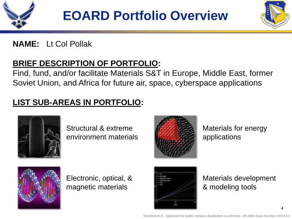
EOARD Portfolio Overview
NAME: Lt Col Pollak
BRIEF DESCRIPTION OF PORTFOLIO:
Find, fund, and/or facilitate Materials S&T in Europe, Middle East, former
Soviet Union, and Africa for future air, space, cyberspace applications
LIST SUB-AREAS IN PORTFOLIO:
Structural & extreme
environment materials
Electronic, optical, &
magnetic materials
Materials for energy
applications
Materials development
& modeling tools
Distribution A: Approved for public release; distribution is unlimited. 88 ABW Case Number XXXXXX

5
2010 Active Efforts
Russia
High-temp superconductors
Ukraine
Tribology & coatings
Super/magneto-elastic alloys
Ceramic composites
Ultrasonic sensing
UK
Morphing skin materials
High strain rate analysis
Romania
Functionalized DNA
Israel
Silicon-air batteries
Belgium
2-D conjugated polymers
The Netherlands
Hybrid superconductors
Atomic clusters
Austria & Czech Republic
High-temp nanocoatings
France
Multiscale modeling
Organic EO polymers
Portugal
Liquid crystals
Spain
Nano shape memory alloys
Germany
High-throughput experimentation
Italy
Catalytic nanostructures
Ultra high-temp ceramics
Switzerland
High-thruput tribology
Morocco & Egypt
CSP only
Distribution A: Approved for public release; distribution is unlimited. 88 ABW Case Number XXXXXX
6
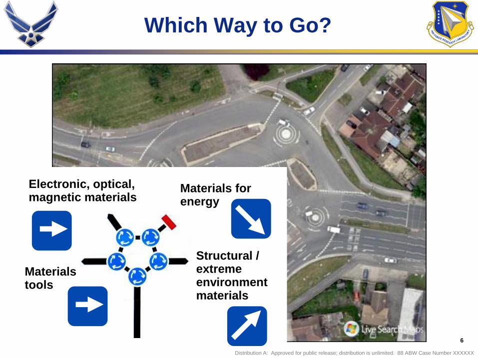
Electronic, optical, magnetic materials
Structural / extreme environment materials
Materials tools
Materials for energy
Which Way to Go?
Distribution A: Approved for public release; distribution is unlimited. 88 ABW Case Number XXXXXX

7
Evolution of Materials ScienceShaping Challenges & Opportunities Ahead
Processing
Structure
Properties
Performance
YESTERDAY / TODAY TODAY / TOMORROW
Design / analysis at
micro-level Design / analysis at
nano & atomic-level
Properties
as outputIntegrated and
inverse design
1 test 1 data point
High-throughput methods
0.0 0.1 0.2 0.3 0.4 0.5 0.6 0.7 0.8 0.9 1.0
0.0
0.1
0.2
0.3
0.4
0.5
0.6
0.7
0.8
0.9
1.00.0
0.1
0.2
0.3
0.4
0.5
0.6
0.7
0.8
0.9
1.0
Pt [a
t.%]P
d [at.%
]
Fe [at.%]
Descriptive modeling Predictive modeling
Destructive / post-
mortem imaging
Non-invasive / near
real-time imaging

8
Broad Scientific Challenges…and Transformational Opportunities
• Predicting compositions and micro/nanostructures of interest for
structural, high temperature, and other materials
Ab initio methods, multi-scale methods, improving computational efficiency
• Rapid screening for mechanical and environmental properties
Bulk properties vs. micro/nano-scale properties, methods of accelerating
degradation, novel rapid fabrication techniques
• Utilizing more available data from conventional tests
Volumetric imaging, quantification of features, novel test techniques
• Consideration to actual state & its evolution in predictive models
Get ―enough but no more‖ data to characterize state, correlate / validate
SHM/NDE techniques, appropriate inputs to damage models
• Other emerging capabilities of AFRL interest?
Enabling future capabilities…
-- Tailor the material systems and structures for the application
-- Efficiently screen and test to validate models and optimize parameters
-- Predict residual properties based on actual state of component

9
Selected Projects
• High-throughput experimentation
• Nanopillar shape memory alloys
• Morphing skin materials
• High strain rate simulation
• X-ray tomography for composites fatigue
10
High-Throughput ExperimentationOptical Screening for Amorphous Materials
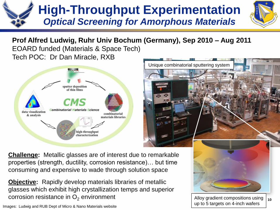
Prof Alfred Ludwig, Ruhr Univ Bochum (Germany), Sep 2010 – Aug 2011
EOARD funded (Materials & Space Tech)
Tech POC: Dr Dan Miracle, RXB
Images: Ludwig and RUB Dept of Micro & Nano Materials website
Unique combinatorial sputtering system
Challenge: Metallic glasses are of interest due to remarkable
properties (strength, ductility, corrosion resistance)… but time
consuming and expensive to wade through solution space
Objective: Rapidly develop materials libraries of metallic
glasses which exhibit high crystallization temps and superior
corrosion resistance in O2 environment Alloy gradient compositions using
up to 5 targets on 4-inch wafers

11
High-Throughput Experimentation(continued)
300 400 500 600 700 800 9000.0010
0.0015
0.0020
0.0025
0.0030
0.0035
717 K
[
Ohm
*m
]
T [K]
689 K
Ramp rate: 1.7 K/s
Approach:
1. Deposit amorphous thin films
2. Determine compositions through automated EDX
3. Characterize structure through automated XRD
and high-throughput resistivity tests as f(T)
4. Develop optical screening method based on
change in reflectivity upon phase change
5. Use reflectivity changes to characterize corrosion
resistance for alloys with high crystallization temp
Automated x-ray diffraction of wafers
(capability -100ºC to 900ºC)
Images: Ludwig and RUB Dept of Micro & Nano Materials website
Resistivity changes indicate crystallization
0.0 0.1 0.2 0.3 0.4 0.5 0.6 0.7 0.8 0.9 1.0
0.0
0.1
0.2
0.3
0.4
0.5
0.6
0.7
0.8
0.9
1.00.0
0.1
0.2
0.3
0.4
0.5
0.6
0.7
0.8
0.9
1.0
Pt [a
t.%]P
d [at.%
]
Fe [at.%]
-1.000
0.3667
1.733
3.100
4.467
5.833
7.200
8.567
9.933
11.30
12.67
14.03
15.40
16.77
18.13
19.50
20.87
22.23
23.60
24.97
26.33
27.70
29.07
30.43
31.80
33.17
34.53
35.90
37.27
38.63
40.00
0.0 0.1 0.2 0.3 0.4 0.5 0.6 0.7 0.8 0.9 1.0
0.0
0.1
0.2
0.3
0.4
0.5
0.6
0.7
0.8
0.9
1.00.0
0.1
0.2
0.3
0.4
0.5
0.6
0.7
0.8
0.9
1.0
Pt [a
t.%]P
d [at.%
]
Fe [at.%]0.0 0.1 0.2 0.3 0.4 0.5 0.6 0.7 0.8 0.9 1.0
0.0
0.1
0.2
0.3
0.4
0.5
0.6
0.7
0.8
0.9
1.00.0
0.1
0.2
0.3
0.4
0.5
0.6
0.7
0.8
0.9
1.0
Pt [a
t.%]P
d [at.%
]
Fe [at.%]
40°C
190°C
210°C
Color code:
Intensity change
proportional to
oxidation
First results of parallel optical screening
of oxidation in air for Fe-Pt-Pd system
(Amorphous Ni-Ti-
based alloy)

12
Nanopillar Shape Memory AlloysNanostructures for Ultra High Damping
Prof Jose San Juan, Univ of Basque Country (Spain), Jul 2010 – Jul 2011
EOARD funded 1st year AFOSR planning 2nd year (Dr Les Lee)
Images: San Juan and San Juan/Nó/Shuh, Nat Nanotechnol 4 (2009)
Challenge: Materials with significant energy absorption / damping
capability needed for blast mitigation and vibration suppression
Objective: Develop large area micro/nano pillars of Cu-Al-Ni shape
memory alloy (SMA) exhibiting high damping (Phase 2—multilayers)
Damping comparison
Damping proportional
to area enclosed
FIB milling
13
Nanopillar Shape Memory Alloys(continued)
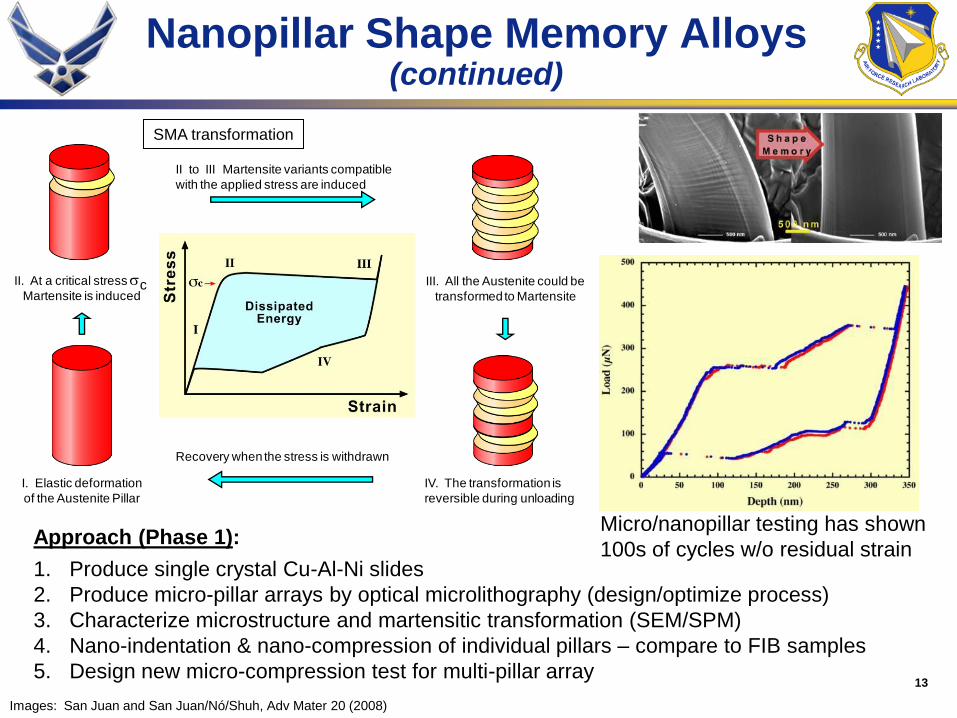
Approach (Phase 1):
1. Produce single crystal Cu-Al-Ni slides
2. Produce micro-pillar arrays by optical microlithography (design/optimize process)
3. Characterize microstructure and martensitic transformation (SEM/SPM)
4. Nano-indentation & nano-compression of individual pillars – compare to FIB samples
5. Design new micro-compression test for multi-pillar array
I. Elastic deformation
of the Austenite Pillar
II. At a critical stress cMartensite is induced
II to III Martensite variants compatible
with the applied stress are induced
III. All the Austenite could be
transformed to Martensite
IV. The transformation is
reversible during unloading
Recovery when the stress is withdrawn
SMA transformation
Micro/nanopillar testing has shown
100s of cycles w/o residual strain
Images: San Juan and San Juan/Nó/Shuh, Adv Mater 20 (2008)

14
Development of Morphing SkinsExample of a Transition Success
Challenge: Morphing skin materials must
allow large area change yet remain strong
Woven/cross-ply reduces area in shear,
but not extensional deformation; while
knitted fabrics have limited elongation
range, less strength, harder to manufacture
Dr Prasad Potluri, Univ of Manchester (UK), Sep 2008 – Nov 2010
EOARD seed funds AFRL/RX funding
Tech POC: Dr Jeff Baur, RXBC
Objective: Develop hyper-elastic yarns for use in woven/cross-ply fabrics
Images: Potluri, AFRL-AFOSR-UK-TR-2010-0003
Tunable by altering
parametersLow modulus
High modulus
Knee point

15
Development of Morphing Skins(continued)
Images: Potluri, AFRL-AFOSR-UK-TR-2010-0003
Biaxial braid set-up
Creating a biaxial braided sample
Triaxial braided yarn
Relaxed vs. stretched(larger extensions in triaxial)
16
Development of Morphing Skins(continued)
Images: Potluri, AFRL-AFOSR-UK-TR-2010-0003
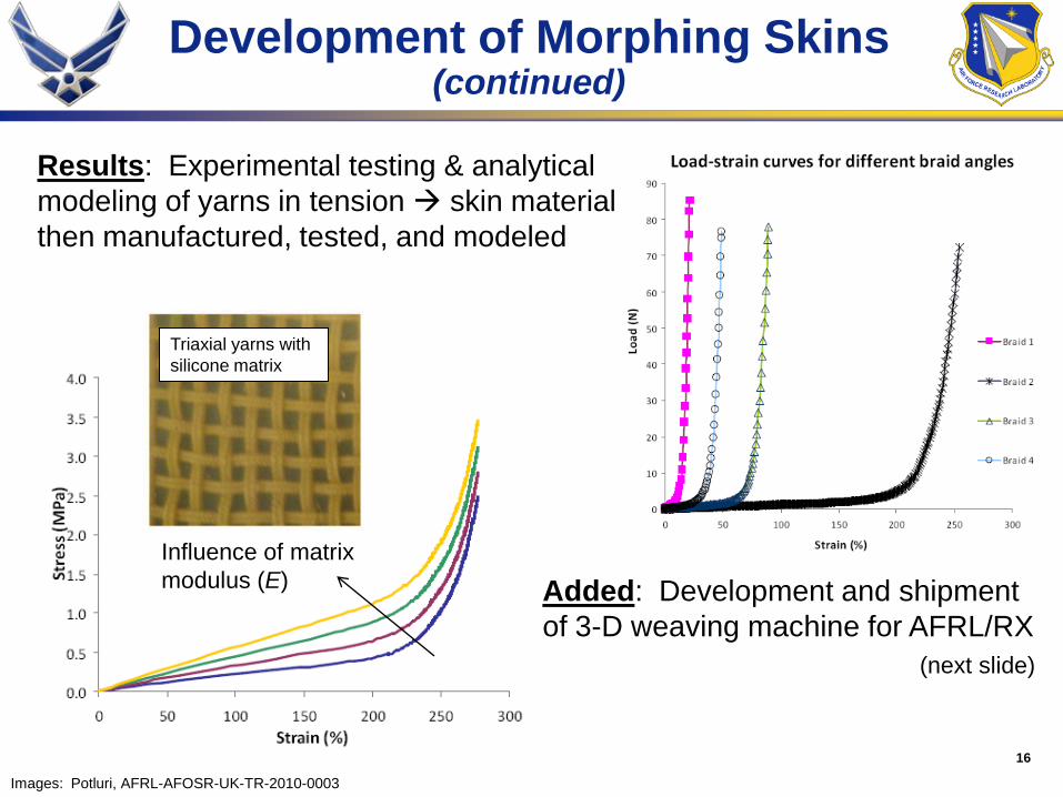
Results: Experimental testing & analytical
modeling of yarns in tension skin material
then manufactured, tested, and modeled
Triaxial yarns with
silicone matrix
Influence of matrix
modulus (E) Added: Development and shipment
of 3-D weaving machine for AFRL/RX
(next slide)

17
Development of Morphing Skins(continued)
Possibilities for use and further collaboration:
• Design/manufacture 3D woven preforms with
various fibers (carbon, glass, ceramic, hybrids)
• Geometrical and meso-mechanical modeling of
textile composites
• Modeling of 3D woven preforms subjected to
forming forces (compaction, in-plane shear,
biaxial tension and bending)
• Addition of smart sensors/actuators in 3D weaves
• Development of novel morphing skins
Image: Potluri, development as of Jan 2010
To be shipped to AFRL/RX after training at
Univ of Manchester (Spring 2011)
18
High Strain Rate AnalysisUsing Low Strain Rate Analogue
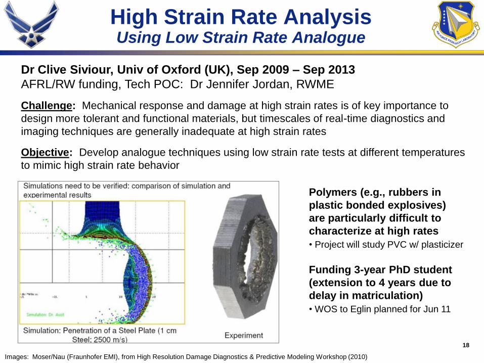
Dr Clive Siviour, Univ of Oxford (UK), Sep 2009 – Sep 2013
AFRL/RW funding, Tech POC: Dr Jennifer Jordan, RWME
Images: Moser/Nau (Fraunhofer EMI), from High Resolution Damage Diagnostics & Predictive Modeling Workshop (2010)
Challenge: Mechanical response and damage at high strain rates is of key importance to
design more tolerant and functional materials, but timescales of real-time diagnostics and
imaging techniques are generally inadequate at high strain rates
Objective: Develop analogue techniques using low strain rate tests at different temperatures
to mimic high strain rate behavior
Polymers (e.g., rubbers in
plastic bonded explosives)
are particularly difficult to
characterize at high rates
• Project will study PVC w/ plasticizer
Funding 3-year PhD student
(extension to 4 years due to
delay in matriculation)
• WOS to Eglin planned for Jun 11

19
Growing Interest in 3-DCharacterization Methods
0
20
40
60
80
100
120
140
160
1990
1991
1992
1993
1994
1995
1996
1997
1998
1999
2000
2001
2002
2003
2004
2005
2006
2007
2008
2009
2010
* ISI Web of Science search: ―x-ray‖ + ―tomography‖ (for subject areas which include ―materials science‖)
DARPA/ONR Dynamic 3-D Digital
Structure Program (FY05-10)
Public
ations*
Snapshots of growing grain using x-ray topotomography
Ludwig et al, Mat Sci Eng A-Strut 524 (2009)
Jun 2010 – ONRG Workshop I
Mar 2011 – ONRG/EOARD Workshop II
20
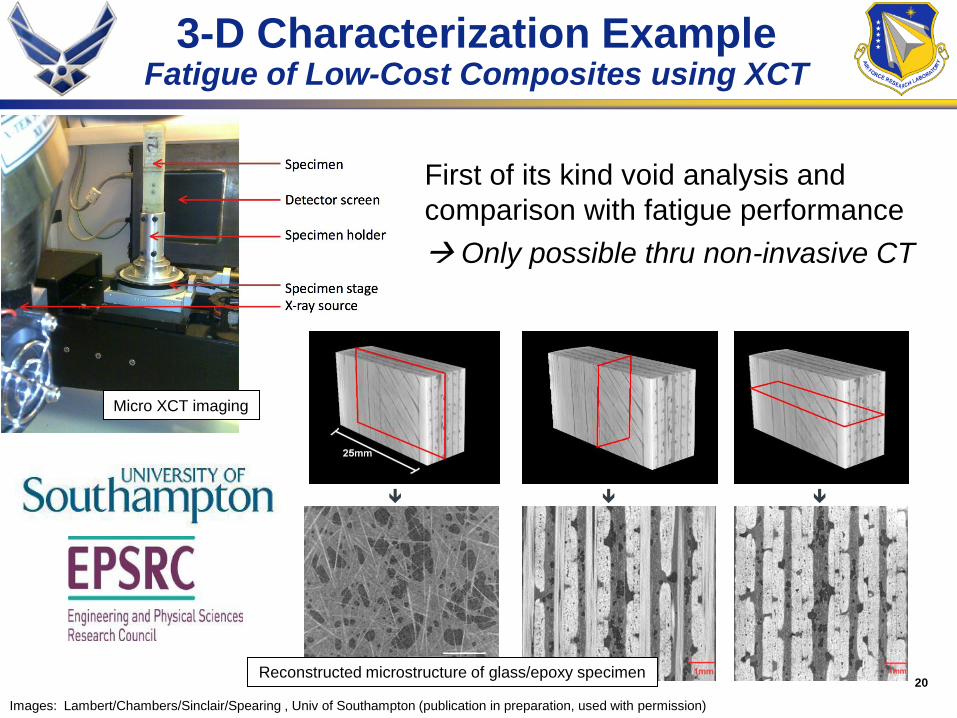
3-D Characterization ExampleFatigue of Low-Cost Composites using XCT
First of its kind void analysis and
comparison with fatigue performance
Only possible thru non-invasive CT
Images: Lambert/Chambers/Sinclair/Spearing , Univ of Southampton (publication in preparation, used with permission)
Micro XCT imaging
Reconstructed microstructure of glass/epoxy specimen
21
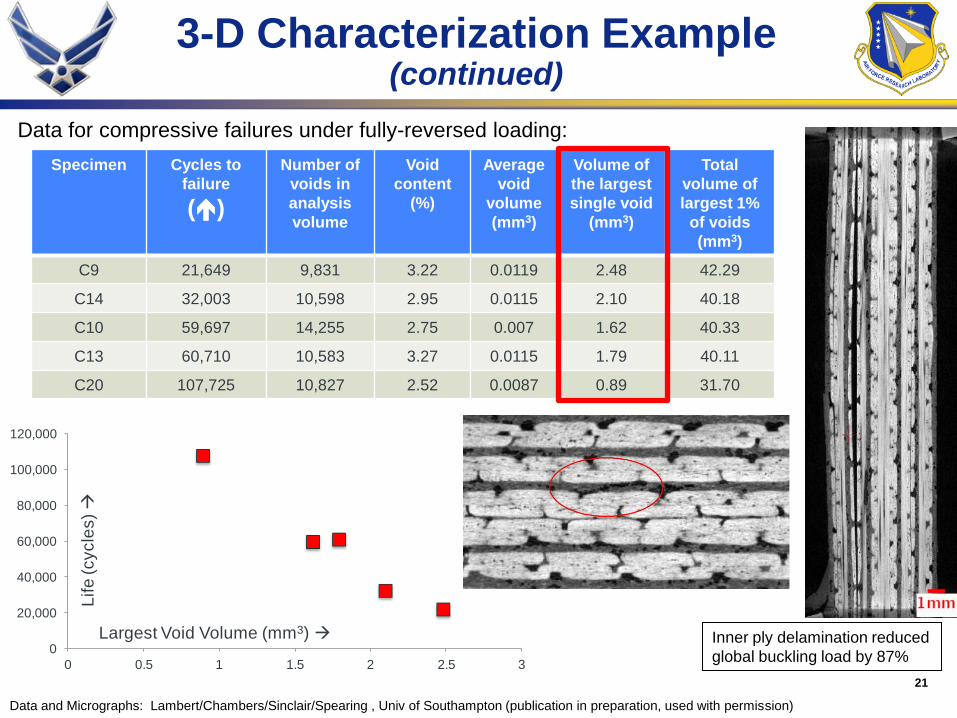
3-D Characterization Example (continued)
Specimen Cycles to
failure
()
Number of
voids in
analysis
volume
Void
content
(%)
Average
void
volume
(mm3)
Volume of
the largest
single void
(mm3)
Total
volume of
largest 1%
of voids
(mm3)
C9 21,649 9,831 3.22 0.0119 2.48 42.29
C14 32,003 10,598 2.95 0.0115 2.10 40.18
C10 59,697 14,255 2.75 0.007 1.62 40.33
C13 60,710 10,583 3.27 0.0115 1.79 40.11
C20 107,725 10,827 2.52 0.0087 0.89 31.70
0
20,000
40,000
60,000
80,000
100,000
120,000
0 0.5 1 1.5 2 2.5 3
Largest Void Volume (mm3)
Life
(cycle
s)
Inner ply delamination reduced
global buckling load by 87%
Data for compressive failures under fully-reversed loading:
Data and Micrographs: Lambert/Chambers/Sinclair/Spearing , Univ of Southampton (publication in preparation, used with permission)

22
Understanding Fatigue Damage inComposites through Microtomography
Images: Sinclair/Spearing
Challenge: Accurate modeling / prediction of damage processes in composites requires
identification, quantification, and understanding of key internal microscale features
Objective: Use high-res XCT to investigate fatigue of fiber-reinforced aerospace composite
– identify critical features, develop detection techniques, statistically quantify, link to models
Expected Payoffs: Insights, inputs, and validation for AFRL composite materials damage
modeling, jumping point for future investigations exploiting tomography data
In situ XCT of carbon/epoxy composite damage
Transverse (90º) cracking
Longitudinal (0º) cracking
Delamination
0º fiber breaks
Prof Ian Sinclair and Prof Mark Spearing, IN DEVELOPMENT FOR 2011
EOARD (w/ ONRG contribution) to fund 3-yr PhD student

23
Theme for Way Ahead
Needs Background
Opportunities
• Failure of structural materials
• Nanotech for structural,
thermal, & health monitoring
• Probabilistics / T&E / Sys Eng
• Better / more predictive modeling
• Optimizing parameters at nanoscale
• Reduce materials development cycle
• European excellence in hybrids and composites
• High-throughput experimental and predictive technologies
• High-resolution imaging capabilities
• DoD interest and activity in non-invasive characterization
Reduce development cycle by
developing novel data-rich
methods to predict, develop, test,
& monitor aerospace materials

24
Wrap Up
• Portfolio spans materials
spectrum supporting AFRL
• Looking for technologies with
relatively broad impact to reduce
materials development cycle
• Emphasis on structural and
environmental, but not exclusive
Lt Col Randall ‗Ty‘ Pollak
EOARD
Unit 4515
APO, AE 09421-0014
DSN 314-235-6115
Comm +44 1895-616115
25
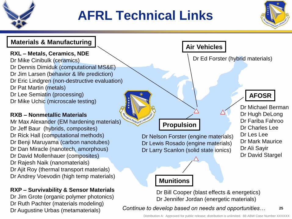
AFRL Technical Links
Munitions
Dr Bill Cooper (blast effects & energetics)
Dr Jennifer Jordan (energetic materials)
Materials & Manufacturing
AFOSR
Dr Michael Berman
Dr Hugh DeLong
Dr Fariba Fahroo
Dr Charles Lee
Dr Les Lee
Dr Mark Maurice
Dr Ali Sayir
Dr David Stargel
RXL – Metals, Ceramics, NDE
Dr Mike Cinibulk (ceramics)
Dr Dennis Dimiduk (computational MS&E)
Dr Jim Larsen (behavior & life prediction)
Dr Eric Lindgren (non-destructive evaluation)
Dr Pat Martin (metals)
Dr Lee Semiatin (processing)
Dr Mike Uchic (microscale testing)
RXB – Nonmetallic Materials
Mr Max Alexander (EM hardening materials)
Dr Jeff Baur (hybrids, composites)
Dr Rick Hall (computational methods)
Dr Benji Maruyama (carbon nanotubes)
Dr Dan Miracle (nanotech, amorphous)
Dr David Mollenhauer (composites)
Dr Rajesh Naik (nanomaterials)
Dr Ajit Roy (thermal transport materials)
Dr Andrey Voevodin (high temp materials)
RXP – Survivability & Sensor Materials
Dr Jim Grote (organic polymer photonics)
Dr Ruth Pachter (materials modeling)
Dr Augustine Urbas (metamaterials)
Air Vehicles
Dr Ed Forster (hybrid materials)
Dr Nelson Forster (engine materials)
Dr Lewis Rosado (engine materials)
Dr Larry Scanlon (solid state ionics)
Propulsion
Continue to develop based on needs and opportunities…
Distribution A: Approved for public release; distribution is unlimited. 88 ABW Case Number XXXXXX


