

7/31/2019 9 Basic Ic
http://slidepdf.com/reader/full/9-basic-ic 1/26
I NT EGRAT ED CI RCUI T

7/31/2019 9 Basic Ic
http://slidepdf.com/reader/full/9-basic-ic 2/26
I C FABRI CAT I ON PROCESS
I C Fabrication Process

7/31/2019 9 Basic Ic
http://slidepdf.com/reader/full/9-basic-ic 3/26
I C DENSI T Y
1. Small Scale I C (SSI )
2. Medium Scale I C (MSI )3. Large Scale I C (LSI )
4. Very Large Scale I C (VLSI )
Relative Component Count of I C’s

7/31/2019 9 Basic Ic
http://slidepdf.com/reader/full/9-basic-ic 4/26

7/31/2019 9 Basic Ic
http://slidepdf.com/reader/full/9-basic-ic 5/26
I C PACKAGES

7/31/2019 9 Basic Ic
http://slidepdf.com/reader/full/9-basic-ic 6/26
I C PACKAGE
Dual I nline Package (DI P)
Pin Grid Array (PGA)
Ball Grid Array (BGA)
Small Outline I C(SOI C)
Plastic Lead Chip Carrier (PLCC)

7/31/2019 9 Basic Ic
http://slidepdf.com/reader/full/9-basic-ic 7/26
I C
Complete Circuit in One Package

7/31/2019 9 Basic Ic
http://slidepdf.com/reader/full/9-basic-ic 8/26
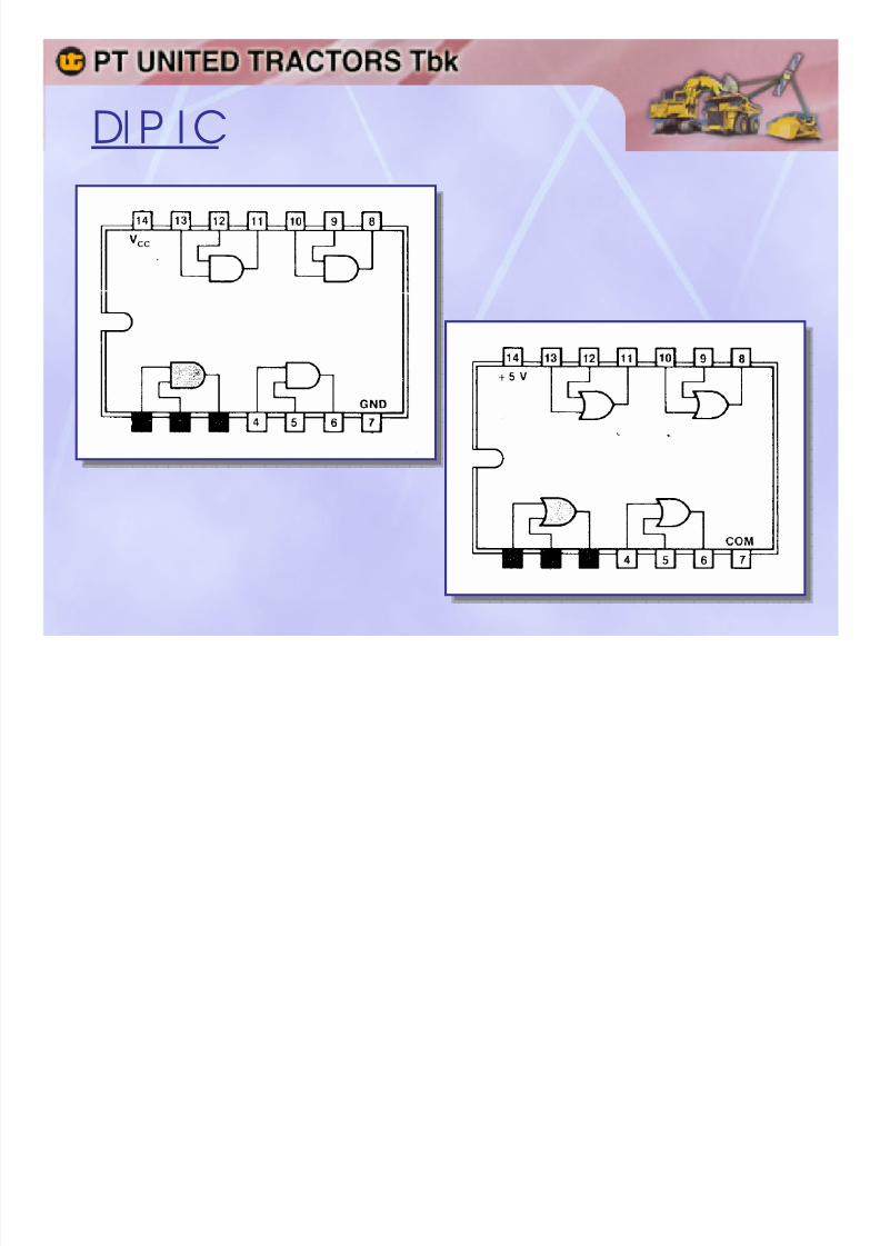
DI P I C
1. COMMON LOGI C I C (14- and 16-pin)
2. MEMORY IC (16-, 18-, 24- and 28-pin)
3. MI CROPROCESSOR I C (40-, 44- and 48-pin)
DI P IC PIN NUMBERI NG
7/31/2019 9 Basic Ic
http://slidepdf.com/reader/full/9-basic-ic 9/26
DI P I C

7/31/2019 9 Basic Ic
http://slidepdf.com/reader/full/9-basic-ic 10/26
74 SERI ES I C CODE
DM 7400 xxx NDM 7400 xxx N
Manufactur e Code
Denotes Specif icat ion and T ype of I C :L = Low Power (I C T T L)
LS = Low Power, Schottky (I C T T L)
ALS = Advanced, Low Power, Schottky (I C T T L)
H = High Speed (I C T T L)
C = Complementary MOSFET (I C CMOS)
HC = High Speed, Complementary MOSFET (I C CMOS)HCT = High Speed, Complementary MOSFET , I nput T T L (I C CMOS)
Denotes I C Special Funct ion
Denotes improvements f rom manufacture

7/31/2019 9 Basic Ic
http://slidepdf.com/reader/full/9-basic-ic 11/26
74 SERI ES I C FAMI LY
1. 7400 = NAND
2. 7402 = NOR
3. 7404 = NOT / INVERT ER
4. 7407 = YES / BUFFER
5. 7408 = AND
6. 7432 = OR
7. 7447 = 7 SEGMENT DI SPLAY DRI VER (COMMON CAT HODE)8. 7448 = 7 SEGMENT DI SPLAY DRI VER (COMMON ANODE)
9. 7474 = D FLIP-FLOP
10. 7490 = DECADE COUNT ER
11. 74138 = 3 T O 8 DECODER
12. 74153 = 4 T O 1 MULT I PLEXER13. 74157 = 2 T O 1 MULT I PLEXER
14. 74160 = SYNCHRONOUS BI NARY COUNT ER
15. 74164 = SHI FT REGI STER
16. 74174 = D FLI P-FLOP WI T H COMPLEMENT OUT PUT
17. 74193 = SYNCHRONOUS UP/DOWN BI NARY COUNT ER

7/31/2019 9 Basic Ic
http://slidepdf.com/reader/full/9-basic-ic 12/26
40 SERI ES I C CODE
CD 4001 B ECD 4001 B E
Manufactur e Code
Denotes Plast ic for Double I nput
Denotes I C Special Funct ion
Denotes improvements f rom manufacture

7/31/2019 9 Basic Ic
http://slidepdf.com/reader/full/9-basic-ic 13/26
40/45 SERI ES I C FAMI LY1. 4011 = NAND
2. 4001 = NOR
3. 4009 = NOT / INVERT ER
4. 4010 = YES / BUFFER
5. 4017 = DECADE COUNT ER
6. 4021 = 8 BIT STAT I C SHIFT REGI ST ER
7. 4052 = 4 CHANNEL MULT I PLEXER
8. 4053 = 2 CHANNEL MULT I PLEXER
9. 4071 = OR
10. 4081 = AND
11. 40147 = 10 T O 4 LI NE BCD PRI ORI T Y ENCODER
12. 40174 = D FLI P-FLOP13. 4510 = PRESET T ABLE UP/DOWN BCD COUNT ER
14. 4511 = 7 SEGMENT DRI VER (COMMON CAT HODE)
15. 4513 = 7 SEGMENT DRI VER (COMMON ANODE)
16. 4515 = 4 T O 16 LI NE DECODER
17. 4518 = BCD UP COUNT ER

7/31/2019 9 Basic Ic
http://slidepdf.com/reader/full/9-basic-ic 14/26
I C PROPAGAT I ON DELAY

7/31/2019 9 Basic Ic
http://slidepdf.com/reader/full/9-basic-ic 15/26
LOGI C LEVEL
HI GH
HI GH
LOW
LOW
T HERESHOLD
T HERESHOLD
VCC VDD
GND VS S

7/31/2019 9 Basic Ic
http://slidepdf.com/reader/full/9-basic-ic 16/26
CONT ROL CI RCUI T
Active High
Active Low

7/31/2019 9 Basic Ic
http://slidepdf.com/reader/full/9-basic-ic 17/26
T T L I C

7/31/2019 9 Basic Ic
http://slidepdf.com/reader/full/9-basic-ic 18/26
T T L I C
T T L (T ransistor-T ransistor Logic) is the best
established and most diversified I C family. LS(Low-power Schottky) is functionally identical toT T L but is slightly faster and use 80% less power.T T L/LS chips require a regulated 4,75 – 5,25 voltpower supply. Here’s a simple battery supply :
T he diode drops the battery voltage a safe level.Both capacitors should be installed on the T T L/LS
circuit board. Circuit with lots of T T L/LS chips canuse lots of current. Use a commercial 5 volt linepowered supply to save batteris.

7/31/2019 9 Basic Ic
http://slidepdf.com/reader/full/9-basic-ic 19/26
T T L LOGI C I NPUT
Active High
Active Low

7/31/2019 9 Basic Ic
http://slidepdf.com/reader/full/9-basic-ic 20/26
T T L I C DRIVER
T T L I C Driver

7/31/2019 9 Basic Ic
http://slidepdf.com/reader/full/9-basic-ic 21/26
CMOS I C

7/31/2019 9 Basic Ic
http://slidepdf.com/reader/full/9-basic-ic 22/26
CMOS I C
MOS (Metal Oxide Semiconductor) I Cs can contain more
functions per chip than T T L/LS and very easy to use. Mostchips in this section are C-MOS (Complementary MOS).T hey consume very little power and operate over a 3-15volt range.
CMOS can be powered by this :
Or you can use a line powered supply made from an I CVoltage Regulator 7805/7812/7815.
I ncidentally, you can power a CMOS circuit from two seriesconnected penlights cells, but a 9-12 volt supply will givebetter performance.
7/31/2019 9 Basic Ic
http://slidepdf.com/reader/full/9-basic-ic 23/26
CMOS OPERAT I ON
1. T he input voltage should not exceed VDD (except 4049
and 4050)2. Avoid, if possible, slowly rising and falling input signals
since they can cause excessive power consumption.Rise-time faster than 15 microseconds are best.
3. All unused input must be connected to VDD (+) or VSS(GND). Otherwise erratic chip behavior and excessivecurrent consumption will occur.
4. Never connect an input signal to a CMOS circuit whenpower is off.

7/31/2019 9 Basic Ic
http://slidepdf.com/reader/full/9-basic-ic 24/26
CMOS PRECAUT I ON
1. Never store MOS I Cs in non-conductive plastic
snow, trays, bags or foam.2. Place MOS I Cs pins down on an aluminum foil
sheet or tray when they are not in a circuit or
stored in conductive foam.3. Use a battery powered iron to solder MOS
chips. Do not use an AC powered iron.

7/31/2019 9 Basic Ic
http://slidepdf.com/reader/full/9-basic-ic 25/26
CMOS LOGI C I NPUT
Active High
Active Low

7/31/2019 9 Basic Ic
http://slidepdf.com/reader/full/9-basic-ic 26/26
SCHMI T T T RI GGER


