


A Family of CIM EMS Exchange Standards based on CIM/XML (61970-552)
- Static Network Model Exchange (61970-452)- Dynamic Model Exchange?
- Schematic Layout Exchange (61970-453)- Solved State Exchange (61970-456)
- EMS Static Model Update (proposed)- - Contingency Definition?
- …
Jay Britton

3 3
The Basic Model Exchange Business Problem
The members of an interconnection share a mutual necessity to achieve: Accurate assessment of grid reliability.
Appropriate, timely response to insecure conditions.
A pre-requisite to the above are: Accurate, up-to-date network models.
Consistent network models (at each responsible site).
In an interconnection, this requires: Exchange of models.
Exchange of solved analytical results.
2008 NERC Real-Time Best Practices Report: “Although defining the elements represented in internal network models is relatively
straightforward, the task force finds that defining the elements to be represented in external models is much more complex.”
“Issue #5: External Modeling and Data Exchange Practices Should be Improved by Explicit Reference to the Definition of the Wide-Area-View Boundary. A consistent, uniform set of modeling and data exchange practices, procedures, and standards are needed to support creation and maintenance of accurate external models…”
These requirements apply in operations and planning contexts.
4 4
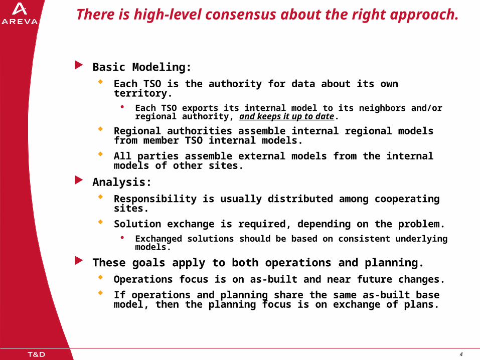
There is high-level consensus about the right approach.
Basic Modeling: Each TSO is the authority for data about its own territory.
Each TSO exports its internal model to its neighbors and/or regional authority, and keeps it up to date.
Regional authorities assemble internal regional models from member TSO internal models.
All parties assemble external models from the internal models of other sites.
Analysis: Responsibility is usually distributed among cooperating sites.
Solution exchange is required, depending on the problem. Exchanged solutions should be based on consistent underlying
models.
These goals apply to both operations and planning. Operations focus is on as-built and near future changes.
If operations and planning share the same as-built base model, then the planning focus is on exchange of plans.

5 5
Contributing Use Cases
Exchange of network models. EMS A and B are neighbors in an interconnection and therefore each needs
to represent the other as part of its external model.
Requires exchange of internal models.
Scope is limited to network data and measurement placements.
Exchange of schematics with models is desirable.
Common Modeling Source between planning and operations. One modeling application for the enterprise.
An EMS requires a model that covers any point in time.
Other targets require data for a specific “case”.
Exchange of solved cases. Several variations… Real-time exchange among different applications.
Real-time cases to study or planning.
Exchange of study or planning cases between different tools.
Import of study cases to EMS.
ENTSO-E DACF. Study cases are generated for the next day by each TSO representing the
expected state of their internal network.
6 6
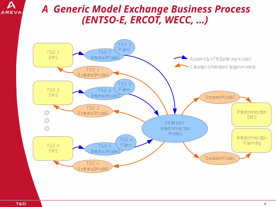
A Generic Model Exchange Business Process(ENTSO-E, ERCOT, WECC, …)
PRIMARY Interconnection
Model
Derived Model
TSO 1 External Model
Assembly of full primary model
Creation of derived target models
TSO 1 EMS
TSO 2 EMS
TSO n EMS
Interconnection EMS
TSO 1 Internal Model
TSO 2External Model
TSO 2 Internal Model
TSO n External Model
TSO n Internal Model
Interconnection Planning
Derived Model
TSO 1 Plans
TSO 2 Plans
TSO n Plans

7 7
Preview – We are working toward defining model partitioning into non-overlapping XML submodels that satisfy all of the use
cases.
Global Model Objects
Regional EMS Static Model
Bndry
Regional EMS Static Model
Regional EMS Static Model
Bndry
Partition by Object Instance using Model Authority Sets
Par
titio
n by
CIM
Sch
ema
Ele
men
ts
Common Objects
Display Layout
Equip Model
Display Layout
Equip Model
Display Layout
Equip Model
Solution
Measurements
Meas
State Variables
Topology
Measurements
Meas
Measurements
Meas
8 8
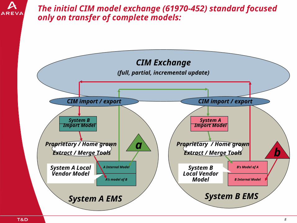
CIM Exchange(full, partial, incremental update)
The initial CIM model exchange (61970-452) standard focused only on transfer of complete models:
A Internal Model
A’s model of B
baProprietary / Home grown
Extract / Merge Tools
Proprietary / Home grown
Extract / Merge Tools
CIM import / export
System A Local Vendor
Model
System A Import Model
B’s Model of A
B Internal Model
System B Local Vendor
Model
System B Import Model
CIM import / export
System A EMS System B EMS
9 9
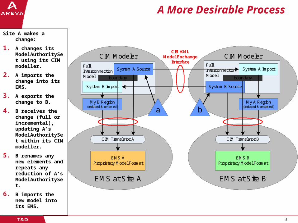
A More Desirable Process
CIM ModelerFullInterconnectionModel
CIM ModelerFullInterconnectionModel
EMS at Site BEMS at Site A
System A Source
System B Import
boundary
System B Source
System A Import
boundary
My A Region(reduced & renamed)
My B Region(reduced & renamed)
CIM Translator A
EMS AProprietary Model Format
CIM Translator B
EMS BProprietary Model Format
CIM/XMLModel Exchange
Interface
a b
Site A makes a change:
1. A changes its ModelAuthoritySet using its CIM modeller.
2. A imports the change into its EMS.
3. A exports the change to B.
4. B receives the change (full or incremental), updating A’s ModelAuthoritySet within its CIM modeller.
5. B renames any new elements and repeats any reduction of A’s ModelAuthoritySet.
6. B imports the new model into its EMS.

10 10
Merge/Extract with Model Authority Sets
Each object is in one and only one set.
Simple labeling technique for assigning responsibility.
Associations connect some objects that are in different sets.
Currently directional from n to 1 (“foreign key” convention) – under discussion.
Regional Sets: No associations with other
regional sets.
External associations to boundary sets only.
Boundary Sets: External associations from
regional sets.
External associations with other boundary sets.
A regional set may be referentially validated independent of other regional sets.
Modeling processes can proceed independently in each region.
Goal: Maximize independence.
Design boundary sets to achieve:
Minimum data Infrequent change
Model Authority SetB
Model Authority SetA
Model Authority SetC
A-B boundaryMAS
B-C
bou
ndar
yM
AS
A-C
bou
ndar
yM
AS

11 11
Typical North American Operations Boundary
Model Authority Set C
A-C Boundary
Set
CN
Model Authority SetA
TT LS
A Region Transmission Line
C Region Substation
m
Tie Line Metering Point
T
T
CB
CN
T
T
CB
T
T
CB
T
BB
ST
GEO=’C’
LN
GEO=’A’
12 12
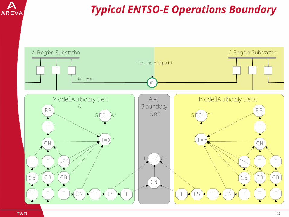
Typical ENTSO-E Operations Boundary
Model Authority Set CA-C Boundary
Set
CN
Model Authority SetA
T
T
CB
CN
Tie Line
C Region Substation
m
T
T
CB
T
T
CB
Tie Line Mid-point
A Region Substation
CN
T
BB
TLST
T
T
CB
CN
T
T
CB
T
T
CB
T
BB
TLSTCN
STST
GEO=’C’GEO=’A’
LN=’X-Y’
ST=’X’ ST=’Y’
13 13
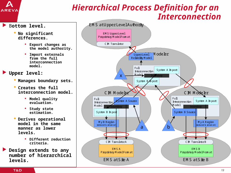
Hierarchical Process Definition for an Interconnection
Bottom level.
No significant differences.
Export changes as the model authority.
Import externals from the full interconnection model.
Upper level:
Manages boundary sets.
Creates the full interconnection model.
Model quality evaluation.
Study state estimation.
Derives operational model in the same manner as lower levels.
Different reduction criteria.
Design extends to any number of hierarchical levels.
CIM Modeler
CIM ModelerFullInterconnectionModel
CIM ModelerFullInterconnectionModel
EMS at Site BEMS at Site A
System A Source
System B Import
boundary
System B Source
System A Import
boundary
My A Region(reduced & renamed)
My B Region(reduced & renamed)
CIM Translator A
EMS AProprietary Model Format
CIM Translator B
EMS BProprietary Model Format
a b
FullInterconnectionModel
System A Import
System B Import
boundary x
Upper Level Reliability Model
EMS at Upper Level Authority
CIM Translator
EMS Upper LevelProprietary Model Format
14 14
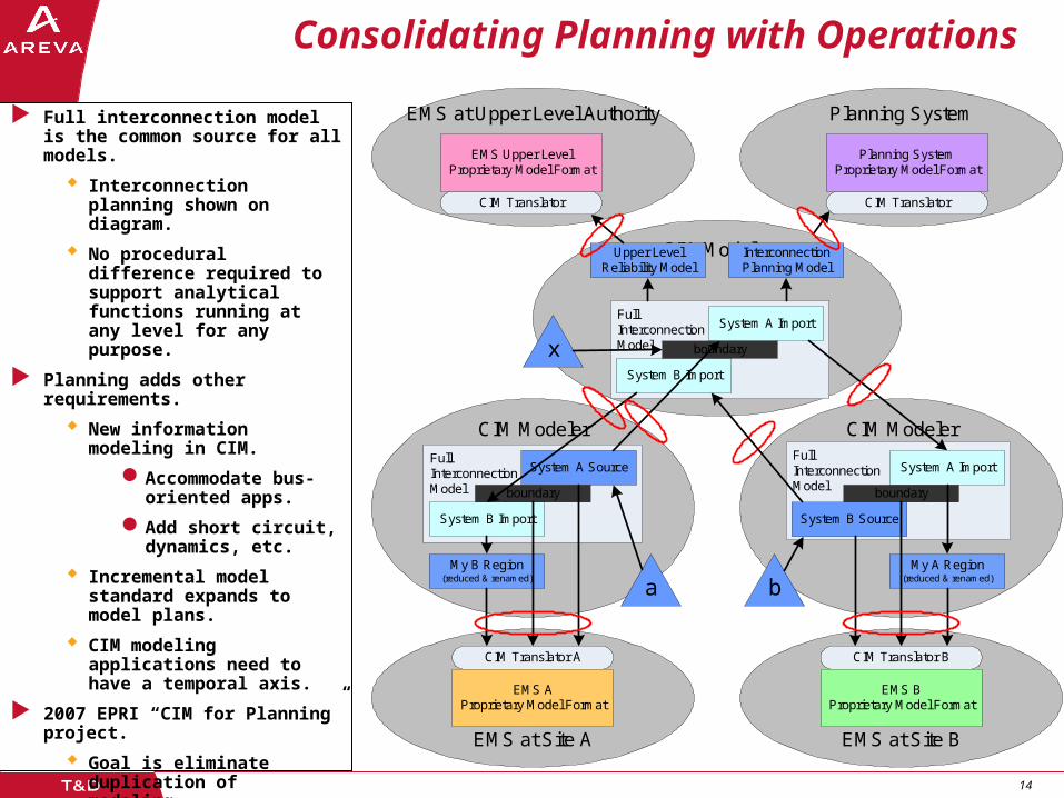
Consolidating Planning with Operations
CIM Modeler
CIM ModelerFullInterconnectionModel
CIM ModelerFullInterconnectionModel
EMS at Site BEMS at Site A
System A Source
System B Import
boundary
System B Source
System A Import
boundary
My A Region(reduced & renamed)
My B Region(reduced & renamed)
CIM Translator A
EMS AProprietary Model Format
CIM Translator B
EMS BProprietary Model Format
a b
FullInterconnectionModel
System A Import
System B Import
boundary x
Upper Level Reliability Model
EMS at Upper Level Authority
CIM Translator
EMS Upper LevelProprietary Model Format
Interconnection Planning Model
Planning System
CIM Translator
Planning SystemProprietary Model Format
Full interconnection model is the common source for all models.
Interconnection planning shown on diagram.
No procedural difference required to support analytical functions running at any level for any purpose.
Planning adds other requirements.
New information modeling in CIM.
Accommodate bus-oriented apps.
Add short circuit, dynamics, etc.
Incremental model standard expands to model plans.
CIM modeling applications need to have a temporal axis.
2007 EPRI “CIM for Planning” project.
Goal is eliminate duplication of modeling.
15 15
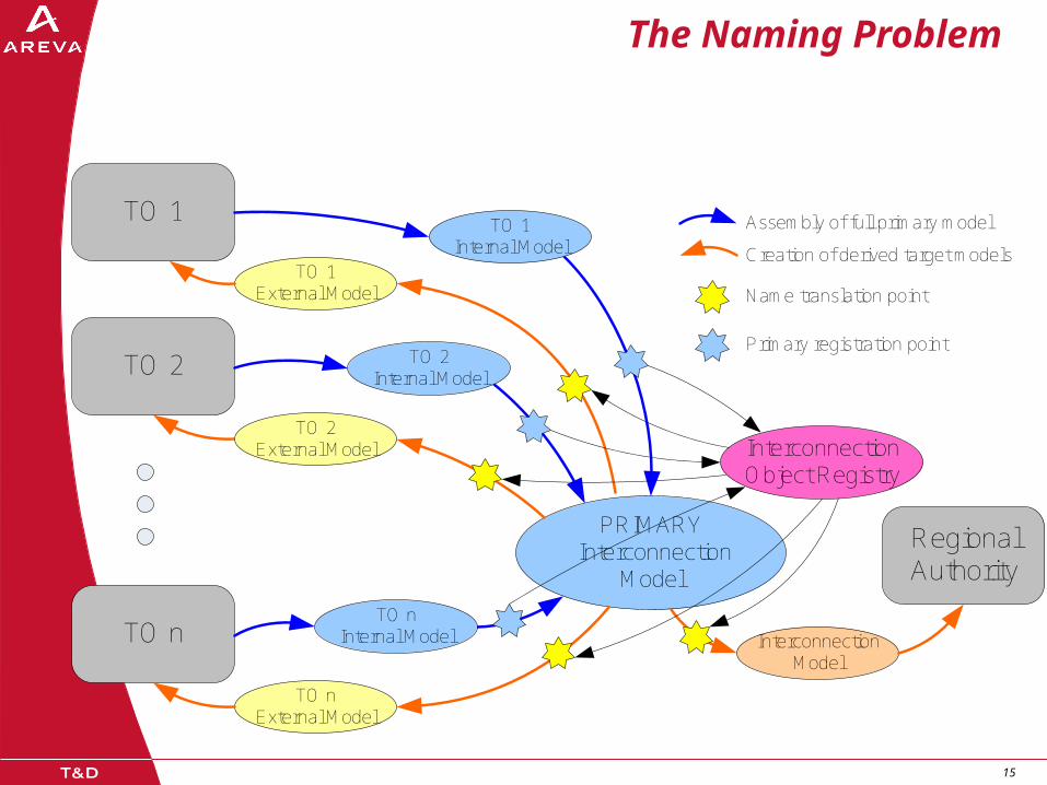
The Naming Problem
PRIMARY Interconnection
Model
Interconnection Model
TO 1 External Model
Assembly of full primary model
Creation of derived target models
TO 1
TO 2
TO n
Regional Authority
TO 1 Internal Model
TO 2External Model
TO 2 Internal Model
TO n External Model
TO n Internal Model
Interconnection Object Registry
Name translation point
Primary registration point
16 16
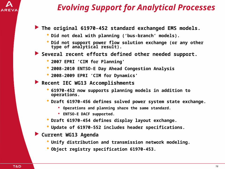
Evolving Support for Analytical Processes
The original 61970-452 standard exchanged EMS models. Did not deal with planning (‘bus-branch’ models).
Did not support power flow solution exchange (or any other type of analytical result).
Several recent efforts defined other needed support. 2007 EPRI ‘CIM for Planning’
2008-2010 ENTSO-E Day Ahead Congestion Analysis
2008-2009 EPRI ‘CIM for Dynamics’
Recent IEC WG13 Accomplishments 61970-452 now supports planning models in addition to operations.
Draft 61970-456 defines solved power system state exchange. Operations and planning share the same standard. ENTSO-E DACF supported.
Draft 61970-454 defines display layout exchange.
Update of 61970-552 includes header specifications.
Current WG13 Agenda Unify distribution and transmission network modeling.
Object registry specification 61970-453.

17 17
Current Modularity
61970-452 Static Model. Equipment Profile.
Identifies equipment and describes basic characteristics. Describes electrical connectivity that would be input to topology processing. (Optional
for planning.) Describes input to functions that derive parameters for a specific point in time. (Optional
for planning.)
Dynamics Profile. Describes dynamic characteristics.
61970-456 Solved Power System State Topology Profile.
The result of topology processing. i.e. Description of how equipment connects into buses and how buses makeup connected systems.
Analogs Profile. The set of SCADA values for analog measurements for a particular point in time.
Status Profile. The state of switches – input to topology processing.
State Variables Profile. This is the set of state variables used in the mathematical formulation that the algorithms
work with.
- Used to represent starting conditions or ending conditions of analysis.
61970-454 Display Layouts The position of objects within a schematic or geographic presentation.

18 18
61970 Profiles

19 19
Dependency Relationships to be
Expressed in Headers
Equipment Model
TopologyState
VariablesCommon Objects
C1 S1T1E1
E1.1
T1.1
T1.2
T1.3
S10
S9
S8
S7
S6
S5
S4
S3
S2
S12
S11

20 20
DACF Process
text
text
text
TSO
X-NodeList
TSO
TSO TSO TSO
TSO My TSO
My TSO
Export my TSO Model to UCTE Server
Import neighbor TSOs from UCTE Server
Merge
Impo
rt a
ll T
SO
mod
els
to
UC
TE
Ser
ver
TSO
TSO
TSO
UCTE Model Server
My TSO’s Cases for Export
My TSO
Model Maintenance
text
TSO
TSO TSO TSO
TSO My TSO
My TSO’s Congestion Analysis Model
text
TSO
TSO TSO TSO
TSO My TSO
Market
Outcomes
Next Day’s Case Development

21 21
Combining profiles into a complete
solution description.
State Variables
TSO Topology
TSO Equipment Model
ACLineSegment
ControlArea
CurrentLimit
CurveData
EnergyConsumer
FossilFuel
GeneratingUnit
GeographicalRegion
HydroGeneratingUnit
HydroPump
MutualCoupling
NuclearGeneratingUnit
OperationalLimitSet
PhaseTapChanger
PowerTransformer
RatioTapChanger
ReactiveCapabilityCurve
RegulatingControl
SeriesCompensator
ShuntCompensator
SubGeographicalRegion
Substation
SvPowerFlow SvShuntCompensatorSections SvTapStepSvVoltage
Switch
SynchronousMachine
Terminal
Terminal (about)
ThermalGeneratingUnit
TieFlow
TopologicalIsland
TopologicalNode
TransformerWinding
VoltageLevel
VoltageLimit
WindGeneratingUnit
UCTE Common Objects BaseVoltage OperationalLimitType
ControlAreaGeneratingUnit
LoadResponseCharacteristic

22 22
Partitioning into Files by TSO
TSO Equipment Model
TSO Topology
TSO Equipment Model
State Variables
X-nodes
TN
TSO Topology
TN
Tie Line
B Region Substation
m
T TLS
T TLS
Tie Line Mid-point
A Region Substation
TLST
TN
TLST
T TLS
T TLS
State Variables FL
FLFL FLV VFL
FL
FL FL FL
FL
FL
TaTa
EG T
Ta
Ta
Ta
EGT
Ta
Ta
FL
FL
FL
Ta
Ta
Ta Ta
Ta
Ta
Ta

23 23
Complete View of Partitioning Into Files
GlobalMA
Regional Solved Case
Equipment Model
Topology
State Variables
Xnode
RegionalSolved Case
Equipment Model
Topology
State Variables
RegionalSolved Case
Equipment Model
Topology
State Variables
Xnode
Partition by Object Instance using Model Authority SetsP
artit
ion
by
CIM
Sch
em
a E
lem
en
ts
Common Objects

24 24
ENTSO-E Interconnection Solution
GlobalMA
Regional Model
Equipment Model
Topology
Xnode
Regional Model
Equipment Model
Topology
Regional Model
Equipment Model
Topology
Xnode
Partition by Object Instance using Model Authority SetsP
artit
ion
by C
IM S
chem
a E
lem
ents
Common Objects
Global SolutionState
Variables

25 25
Partitioning of EMS Static Model
Global Model Objects
Regional EMS Static Model
Bndry
Regional EMS Static Model
Regional EMS Static Model
Bndry
Partition by Object Instance using Model Authority Sets
Par
titio
n by
CIM
Sch
ema
Ele
men
ts
Common Objects
Display Layout
Equip Model
Display Layout
Equip Model
Display Layout
Equip Model

26 26
Partitioning of EMS Solved Cases
Global Model Objects
Regional EMS Static Model
Bndry
Regional EMS Static Model
Regional EMS Static Model
Bndry
Partition by Object Instance using Model Authority Sets
Par
titio
n by
CIM
Sch
ema
Ele
men
ts
Common Objects
Display Layout
Equip Model
Display Layout
Equip Model
Display Layout
Equip Model
Solution
Measurements
Meas
State Variables
Topology
Measurements
Meas
Measurements
Meas

27 27
61970-453 Display Layout Exchange
Purpose: To exchange schematic display layouts accompanying model or solution exchanges.
Corresponds to the part of display maintenance work that normally goes with model maintenance.
Defines graphic objects used in the sender’s displays: Usually linked to a model object, but can also be background.
One or more location coordinates. (Optional glue points.)
Graphic style reference.
Does not define Interpretation of graphic style references.
Usage Sender describes diagram.
Senders disclose the way their system uses graphic styles. Object placements describe sender’s diagram as is.
Receiver must decide how to render the diagram in its system. Create interpretation of sender’s styles. Receivers are not expected to duplicate functionality. Receivers may break apart complex styles or combine simpler styles.
Receiver provides the graphic style interpretation models for their display management software.
Result: Layouts and names of things should be familiar.
Exact replication graphically is likely only when sender and receiver applications are the same.
Exact replication functionally is likely only when sender and receiver applications are the same.

28 28
Display Layout UML Proposal
29 29
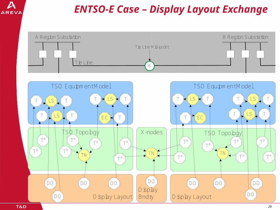
ENTSO-E Case – Display Layout Exchange
Display Bndry
TSO Equipment Model
TSO Topology
TSO Equipment Model
Display Layout
X-nodes
TN
TSO Topology
TN
Tie Line
B Region Substation
m
T TLS
T TLS
Tie Line Mid-point
A Region Substation
TLST
TN
TLST
T TLS
T TLS
Display Layout DO
DODO DODO DO DO
TaTa
EC T
Ta
Ta
Ta
ECT
Ta
Ta
DO
DO
Ta
Ta
Ta Ta
Ta
Ta
Ta


