

GARTEUR AG49 meeting, Name der Sitzung, Folie 1
A modification
of hybrid RANS-LES methods
of DES type
for
flows
around
airplane
wings
Tobias Knopp, DLR, AS-CA
With
contributions
from
Xiaoqin
Zhang, Silvia Reuß, Daria Jakubek,
Christoph Wolf (all DLR) and Axel Probst (TU Braunschweig)
Work
done
in projects
with
Dieter Schwamborn, Roland Kessler (both
DLR AS-CA), Gert Lube
(Uni Gö), Rolf Radespiel (TU BS)

Tobias Knopp, AS-CASE, RETTINA Meeting 10.12.20087
GARTEUR AG49, Meeting 25.9..2009, Folie 2
Outline
Introduction: Aerospace applications
are
„special“Cost
estimate
for
wall-modelled
LES of wing-body
configuration
at
realistic
Reynolds numberFrom
wall-modelled
LES to hybrid RANS-LES (DES-type
coupling)
Shortcomings
of (D)DES for
aerodynamic
flows
at the
onset
of separation
(incipient
separation)
Concept
for
a modified
(D)DES method
based
on properties
of the velocity
profiles
in the
boundary
layer
Conclusions

Tobias Knopp, AS-CASE, RETTINA Meeting 10.12.20087
GARTEUR AG49, Meeting 25.9..2009, Folie 3
Introduction. Aerospace applications
are
„special“

Tobias Knopp, AS-CASE, RETTINA Meeting 10.12.20087
GARTEUR AG49, Meeting 25.9..2009, Folie 4
Aerospace science
applications
are
„special“
Extremely high accuracy demands
(each % in lift and drag is crucial)10% error in viscous drag e.g., due to log-law mismatch is not acceptable
Very high Reynolds numbersCompressor blades
(transonic)u∞
= 400m/s, ρ=1kg/m3, L = 0.05m, µ
= 1.5x10⁻⁵
kg/(ms) Re = 1.3 x 10⁶
A380 at take-offu∞
= 70 m/s, ρ=1kg/m3, L = 10m, µ
= 1.5x10⁻⁵
kg/(ms) Re = 4.6 x 10⁷
Very
large number
of simulations
necessary
for
design
and certificationCertification
demands
20,000-200,000
simulations
for
a variety
of flight
statesMach number
for
different flight
speeds
(Landing/take-off, cruise, dive, …)Reynolds number
variation
(Density
is
a function
of altitude) Angle of attack, control
deflection
devices, …•
Additionally: Geometry
optimization
during
design
phase
Tobias Knopp, AS-CASE, RETTINA Meeting 10.12.20087
GARTEUR AG49, Meeting 25.9..2009, Folie 5
Review
of LES work.
LES convergence
studyfor
grid
and time step
size.
Implications
foraerospace
applications

Tobias Knopp, AS-CASE, RETTINA Meeting 10.12.20087
GARTEUR AG49, Meeting 25.9..2009, Folie 6
Numerical method and LES modellingDLR TAU code with incompressible flow solver THETA
Unstructured finite-volume solver for flows with small compressibility effectsProjection scheme using the interpolation scheme by Rhie
and ChowDiscretization
of convective fluxes using central differencing scheme (CDS)Quadratic upwind scheme was found to be much too dissipative for
LESTime discretization
using 2nd order backward differencing formula (BDF-2)5 times faster than CFX, FLUENT, …Subgrid-scale models: Smagorinsky
model (with van Driest damping)
Calibration
of CSfor
DIT,No tuning
for
more
complex
flows
(see
Knopp, Zhang, Kessler, Lube, CMAME 2010)

Tobias Knopp, AS-CASE, RETTINA Meeting 10.12.20087
GARTEUR AG49, Meeting 25.9..2009, Folie 7
„Grid“
converged
LES solutions
Converged
solutions
w.r.t. time step
size
and spatial
resolution
in the
sense that
mean-flow
and fluctuating
quantities
do not
change
largely
when
refining
the
meshAuthors
opinion:
Static
calibration
of model
coefficients
only
meaningful
after
sufficient convergence
has been
achived
For standard
Smagorinsky: Calibration
of CS
for
DIT „successfully“
applied
to turbulent channel
flow
and backward-
facing
step
without
later
„tuning“Dynamic
calibration
C(U,Δ) which
allows
coarse-grid LES (…
beyond
the
limits of my
intellectual
capabilities…)

Tobias Knopp, AS-CASE, RETTINA Meeting 10.12.20087
GARTEUR AG49, Meeting 25.9..2009, Folie 8
Resolution requirements for wall-resolved LES at low Re Turbulent channel flow Reτ
= 395
Motivation: Wall-resolved
LES avoids
possible
additional problems
(e.g., „log- layer
mismatch“) due
to near-wall
modelling
Required
time step
size
: δt+
= δt uτ2/ν
= 0.4 (precursor
study, Choi
& Moin
JCP 1994)Insufficient
resolution
even
on 64x64x64 mesh, Δx+=39, ∆z+=19.5
Only
on 96x96x96 mesh, results
areclose
to DNS data
No simulation
on 1283
mesh
yet
Standard Smagorinsky
model with
van Driest
damping

Tobias Knopp, AS-CASE, RETTINA Meeting 10.12.20087
GARTEUR AG49, Meeting 25.9..2009, Folie 9
Resolution requirements for wall-modelled LES at high Re Turbulent channel flow Reτ
= 4800Standard Smagorinsky
model
and hybrid wall functions
as near-wall
model, matching
node
at y+=50Unsufficient
resolution
(in space
or
time) causes
log-layer
mismatch
Danger
of 10% error
in viscous
drag

Tobias Knopp, AS-CASE, RETTINA Meeting 10.12.20087
GARTEUR AG49, Meeting 25.9..2009, Folie 10
Resolution requirements
for
flow
over
a backward-facing step
at Reh
=37500 (experiment
by
Driver and Seegmiller)First step: Investigation of required
time steps
size
Second step: Convergence
study on globally
refined
gridsSynthetic
turbulence
at inlet
by
Klein, Sadiki, Janicka
(2003)
On finest
mesh
(219x89x32), resolution
„almost
sufficient“

Tobias Knopp, AS-CASE, RETTINA Meeting 10.12.20087
GARTEUR AG49, Meeting 25.9..2009, Folie 11
Estimation
of costs
for
A380 take-off/landing
Curtisy
by
DLR AS transport
aircraft
branch
Attached
boundary layer
flow
with separation
on flap
of a wing
at high-lift„approximated“
by flow
over
a backward facing
step.
LES with
wall-functionsSurface: 0.38m x 0.05m
Cost:106s on single
CPU (= 20days)
Wing
area: 10m x 40mEstimated
cost:Wall modelled
LES: 4x10¹¹sWall-resolved
LES: 4x10¹⁴s

Tobias Knopp, AS-CASE, RETTINA Meeting 10.12.20087
GARTEUR AG49, Meeting 25.9..2009, Folie 12
Infeasibly
large computational
of wall-resolved
LES at high Re
Estimate
by
Piomelli
(Progress in Aerospace Science, 2008) and Spalart
(1997)Costs
for
resolution
of near-wall
turbulence
dominant in high Re flowsSupposed
reason: Resolution of streaks
(Δx+~450, Δz+~100)
~ Re2.4
~ Re0.6Turbine blade
(transoniccompressor)
A380 wing104
Courtisy
by
Spalart
Conclusion: Treat
(attached) boundary
layers
using
RANS

Tobias Knopp, AS-CASE, RETTINA Meeting 10.12.20087
GARTEUR AG49, Meeting 25.9..2009, Folie 13
F15 3-element airfoil
at high lift. Cost
for
wall-modelled
LESF15 3-Element airfoil
at Re=2Mio, Ma=0.15, incidence
angle 7°
Retracted
chord=1m, L=1.2m, span=0.1cWing
area
= 0.196m2
(both
upper
and lower
side) AWing, F15
/ ABackward
facing
step
= 10 Additional factor
of 5 for
the
surface
grid
due
to surface
curvature
Wall-modelled
LES expensible
but
feasible

Tobias Knopp, AS-CASE, RETTINA Meeting 10.12.20087
GARTEUR AG49, Meeting 25.9..2009, Folie 14
Zonal DES-RANS for
predicting
slat
track
noiseZonal DES for
A320 wing-body-nacelle-pylon30Mio nodes
for
RANS mesh, 50Mio nodes
for
embedded
DES meshSpanwise
extent
of DES mesh: 6% half-spanL=0.308m, Re=1.34x10⁶ is
really
low, Mach number
Ma=0.2, incidence
α=3.93°Computing costs ~ 6month on 2048 cores
Work
by
Silvia Reuss

Tobias Knopp, AS-CASE, RETTINA Meeting 10.12.20087
GARTEUR AG49, Meeting 25.9..2009, Folie 15
Definition of (D)DES.Definition of RANS and LES region

Tobias Knopp, AS-CASE, RETTINA Meeting 10.12.20087
GARTEUR AG49, Meeting 25.9..2009, Folie 16
Design application
for
Detached-Eddy
Simulation (DES)
RANS mode in attached
boundary
layers
Massive separation
treated
in LES mode
Claim of (D)DES: Attached
boundary
layers
treated
in RANS modus,
LES in outer
flow
regions
of large-scale
separation
Deflected
spoiler
Separation point determined
by
the
geometry

Tobias Knopp, AS-CASE, RETTINA Meeting 10.12.20087
GARTEUR AG49, Meeting 25.9..2009, Folie 17
What
is
the
potential of DES for
flows
with
small
separation?
RANS mode in attached
boundary
layersThin
separation
region
in case
of incipient
separation
Claim of (D)DES: Attached
boundary
layers
treated
in RANS modus,
LES in outer
flow
regions
of large-scale
separationBut
(D)DES does
not
really
do this
…

Tobias Knopp, AS-CASE, RETTINA Meeting 10.12.20087
GARTEUR AG49, Meeting 25.9..2009, Folie 18
Non-zonal
hybrid RANS-LES coupling
of DES-type
(D)DES: Different length
scale
substitution
in Spalart-Allmaras
RANS model
DES length
scale
in SA-DDES:
This
is
a hybrid formula
which
can
reduce
to the
following
special
cases:
Formal RANS region: Spalart-Allmaras
RANS model
Formal LES region:
„Smagorinsky
model“
if
left
hand side
is
zero
Function
for
RANS-LES switch
fd
=fd
(ν,d) based
on log-layer
solution
for
ν
in TBL at ZPGRANS and LES region
are
determined
by
fd
(and by
the
mesh)
DESWdW Cdfdd ,0max~
Wdd ~
DESCd~
~ ~

Tobias Knopp, AS-CASE, RETTINA Meeting 10.12.20087
GARTEUR AG49, Meeting 25.9..2009, Folie 19
Short-comings
of SA-(D)DES for
flows
over
airfoils
close
to stall
at incipient
separation
(high-lift)
Tobias Knopp, AS-CASE, RETTINA Meeting 10.12.20087
GARTEUR AG49, Meeting 25.9..2009, Folie 20
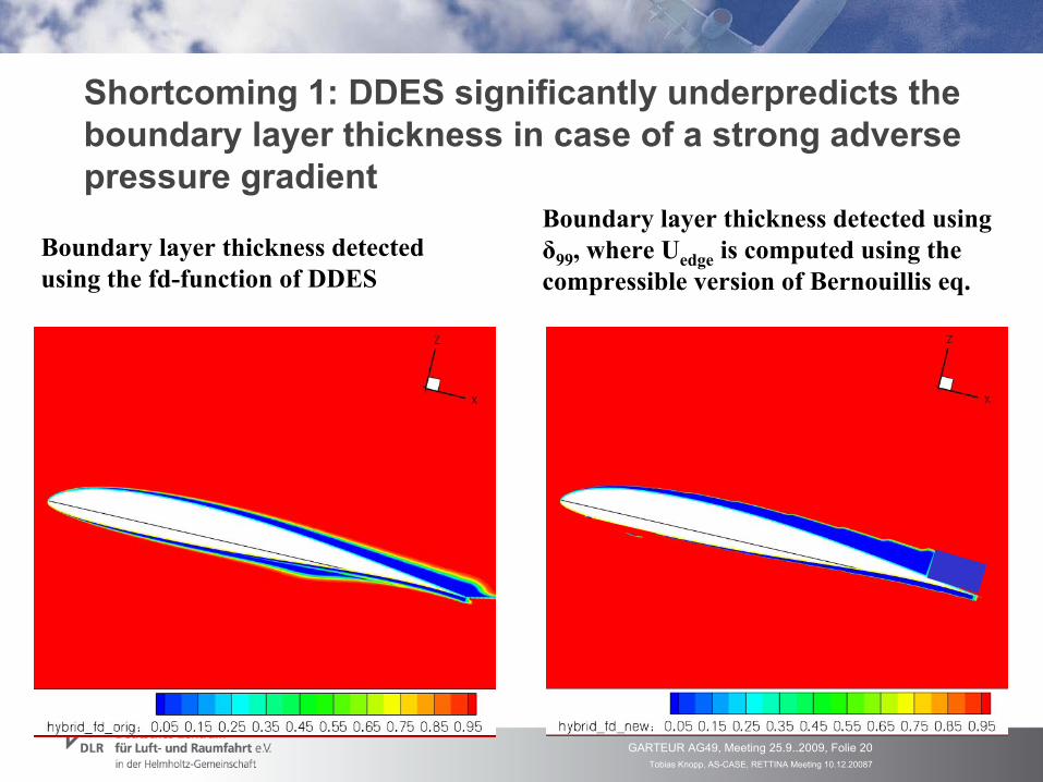
Shortcoming
1: DDES significantly
underpredicts
the boundary
layer
thickness
in case
of a strong
adverse
pressure
gradient
Boundary
layer
thickness
detected using
the
fd-function
of DDES
Boundary
layer
thickness
detected
usingδ99
, where
Uedge
is
computed
using
the compressible
version
of Bernouillis
eq.
Tobias Knopp, AS-CASE, RETTINA Meeting 10.12.20087
GARTEUR AG49, Meeting 25.9..2009, Folie 21
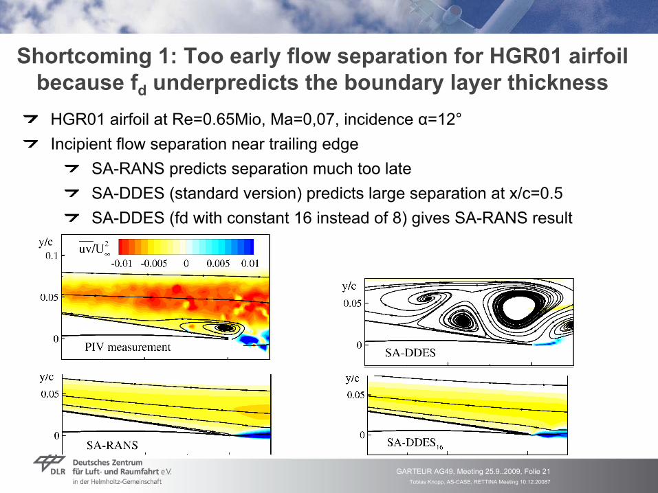
Shortcoming
1: Too
early
flow
separation
for
HGR01 airfoil because
fd
underpredicts
the
boundary
layer
thicknessHGR01 airfoil
at Re=0.65Mio, Ma=0,07, incidence
α=12°
Incipient flow separation near trailing edgeSA-RANS predicts separation much too lateSA-DDES (standard version) predicts large separation at x/c=0.5SA-DDES (fd
with constant 16 instead of 8) gives SA-RANS result

Tobias Knopp, AS-CASE, RETTINA Meeting 10.12.20087
GARTEUR AG49, Meeting 25.9..2009, Folie 22
Extension of the
unstructured
flow
solver
TAUNew data
structure: Approximative wall-normal rays
for
each
wall-node
Computation
of integral boundary
layer
quantities
in wall normal directionStudy
the
form of velocity
profiles
in wall-normal directions

Tobias Knopp, AS-CASE, RETTINA Meeting 10.12.20087
GARTEUR AG49, Meeting 25.9..2009, Folie 23
Velocity profiles
and implications
for
algebraic estimates
of the
boundary
layer
thickness
HGR01 airfoil
at α=13°, Re=0.65Mio, Ma=0.07Suction side at x/c=0.79: Decelerated flow (adverse pressure gradient, APG)
δ99
yΞ‘,min (without
calibration
const)
Proposal
by
Stock & Haase (1987)yΞ,max
(without
calibration
const)Constant
from
Coles law-of-the-wall
APG flow: All estimates
for
BL thickness
can
be
used
Ξ=y du/dy
Tobias Knopp, AS-CASE, RETTINA Meeting 10.12.20087
GARTEUR AG49, Meeting 25.9..2009, Folie 24
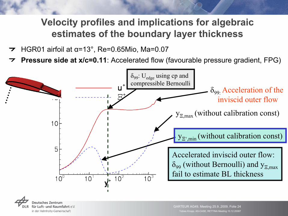
Velocity profiles
and implications
for
algebraic estimates
of the
boundary
layer
thickness
HGR01 airfoil
at α=13°, Re=0.65Mio, Ma=0.07Pressure side at x/c=0.11: Accelerated flow (favourable
pressure gradient, FPG)
δ99: Acceleration
of theinviscid
outer
flow
yΞ‘,min (without
calibration
const)
yΞ,max
(without
calibration
const)
Accelerated
inviscid
outer
flow:δ99
(without
Bernoulli) and yΞ,max
fail
to estimate
BL thickness
δ99
: Uedge
using cp and compressible
Bernoulli

Tobias Knopp, AS-CASE, RETTINA Meeting 10.12.20087
GARTEUR AG49, Meeting 25.9..2009, Folie 25
HGR01-airfoil: Estimation
of boundary
layer
thickness
HGR01 airfoil
at α=13°, Re=0.65Mio, Ma=0.07Suction side: Decelerated flow (adverse pressure gradient, APG)
Flow
separation
fd
significantly
underestimates the
growth of the
BL thickness in streamwise
direction,Independent of factor
8 or
16
Good agreement between
algebraic
BL estimates
yΞ‘,min
and yΞ,max
and δ99
Both
algebraic
BL estimates
drop down in
the
separation
region

Tobias Knopp, AS-CASE, RETTINA Meeting 10.12.20087
GARTEUR AG49, Meeting 25.9..2009, Folie 26
F15 with
prescribed
transition. Wing
upper
side
Attached
wing
BL Free-shear
layer
yΞ‘,min
and yΞ,max
still detect
the
thickness
of the
attached
wing
BL
δ99
detects
the
thickness
of the
free-shear
layer
(slat
wake
and convected
slat
BL)

Tobias Knopp, AS-CASE, RETTINA Meeting 10.12.20087
GARTEUR AG49, Meeting 25.9..2009, Folie 27
Shortcoming
2: Thin
separation
regions
treated
in RANS
Thin
separation
regions
inside
the
boundary
layer
appear
characterize
the boundary
of the
flight
envelope
Incipient
separation
at landing/take-offShock
buffet
at transonic
cruise
(oscillating
shock
and separation
bubble)
DES97, DDES do not
conceived
for
this
flow
situation
α=14degRed: formal RANS-region
of the
DESBlue: formal LES-region
of the
DES
Very
thin
separation
region near
the
trailing
edge

Tobias Knopp, AS-CASE, RETTINA Meeting 10.12.20087
GARTEUR AG49, Meeting 25.9..2009, Folie 28
Shortcoming
2: Thin
separation
regions
treated
in RANS
DDES-16 gives
practically
the
same
result
as SA-RANS
α=14°

Tobias Knopp, AS-CASE, RETTINA Meeting 10.12.20087
GARTEUR AG49, Meeting 25.9..2009, Folie 29
How
to detect
flow
separation? Integral boundary
layer
quantities
Appear
naturally
in the
integral boundary
layer
equation
by
von Karman
Displacement
thickness:
Momentum
thickness:
Shape
factor
(flatness):

Tobias Knopp, AS-CASE, RETTINA Meeting 10.12.20087
GARTEUR AG49, Meeting 25.9..2009, Folie 30
Critical
value
for
the
shape
factor
H at separation?Castillo
et al. (J. Fluids
Eng. 2004)
„…
one
common
design
criterion
for
industrial
turbine
designers
to avoid separation
on compressor
blades is
to not
allow
the
shape
factor
to exceed
2.5…“„…
keep
the
shape
factor
below
2.6 …“
to avoid
separation

Tobias Knopp, AS-CASE, RETTINA Meeting 10.12.20087
GARTEUR AG49, Meeting 25.9..2009, Folie 31
HGR01 at Re=0.65Mio. Criteria
for
flow
separationCriteria
based
on shape
factor
H (for
SA model)
H < 2.4: attached
boundary
layer
flowH > 2.45: separation
region
Criteria
based
on pressure
gradient
parameterΔpx
+
> 1 in the
neighbourhood
of the
separation
point
HGR01 airfoil
atα=14°
Detect
the
region
of flow
separation=> Switch
to LES

Tobias Knopp, AS-CASE, RETTINA Meeting 10.12.20087
GARTEUR AG49, Meeting 25.9..2009, Folie 32
F15 3-element airfoil
with
prescribed
transition. Prediction
of shape
factor
H for
wing
upper
side
For comparison:H~1.3 (ZPG turb. BL), H~2.5 (turb. BL separation)H~2.6 (Blasius profile, ZPG lam. BL), H~3.5 (lam. BL separation)
Use
yΞ‘,min, 2nd in presence
of wake
and free-shear
layer
Cannot
use
δ99
as upper
integral bound

Tobias Knopp, AS-CASE, RETTINA Meeting 10.12.20087
GARTEUR AG49, Meeting 25.9..2009, Folie 33
Shortcoming
3: Too
slow
development
of turbulent content
after
separation
on a single-element
airfoil
2Qinv = ||Ω|| -
||S|| with
2Ω= Grad U –
(Grad U)T, 2S= Grad U + (Grad U)T
HGR01 airfoil
at α=14deg 2D roller
characteristic
for2D URANS (cf. Spalart
2009)
Aim: Force the
generation
of turbulent content
Tobias Knopp, AS-CASE, RETTINA Meeting 10.12.20087
GARTEUR AG49, Meeting 25.9..2009, Folie 34
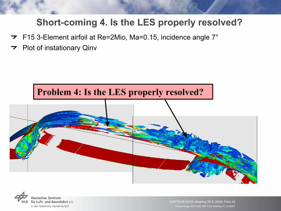
Short-coming
4. Is
the
LES properly
resolved?F15 3-Element airfoil
at Re=2Mio, Ma=0.15, incidence
angle 7°
Plot of instationary
Qinv
Problem 4: Is
the
LES properly
resolved?

Tobias Knopp, AS-CASE, RETTINA Meeting 10.12.20087
GARTEUR AG49, Meeting 25.9..2009, Folie 35
Ad problem
4: Ensure
sufficient
grid
resolution
in LES regions
Coarse
mesh
78x31x16 nodes
x/h -0.5 10∆x+ 660 420∆z+ 300 260
Very
fine mesh
219x89x32 nodes
x/h -0.5 10∆x+ 110 160∆z+ 150 130
Tobias Knopp, AS-CASE, RETTINA Meeting 10.12.20087
GARTEUR AG49, Meeting 25.9..2009, Folie 36
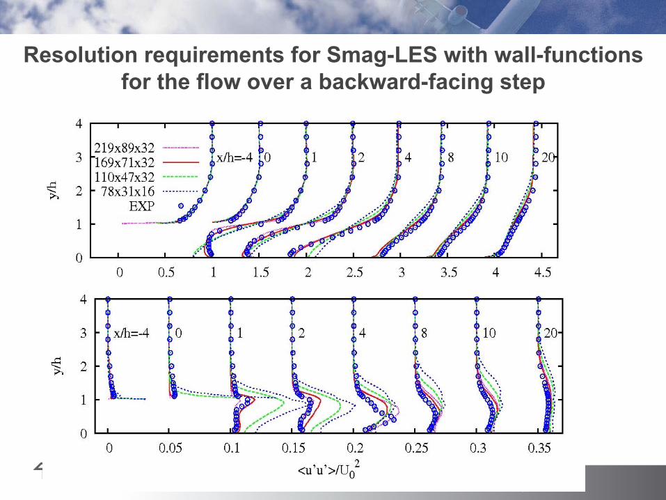
Resolution requirements
for
Smag-LES
with
wall-functions for
the
flow
over
a backward-facing
step

Tobias Knopp, AS-CASE, RETTINA Meeting 10.12.20087
GARTEUR AG49, Meeting 25.9..2009, Folie 37
Single-grid
estimator
for
resolved
turbulent kinetic
energy
Coarse
mesh: S(x) < 0.8 Very
fine mesh: S(x)>0.9
Top-hat
filter

Tobias Knopp, AS-CASE, RETTINA Meeting 10.12.20087
GARTEUR AG49, Meeting 25.9..2009, Folie 38
Zonal DES-RANS for
predicting
slat
track
noiseZonal DES for
A320 wing-body-nacelle-pylon30Mio nodes
for
RANS mesh, 50Mio nodes
for
embedded
DES meshSpanwise
extent
of DES mesh: 6% half-spanL=0.308m, Re=1.34x10⁶ is
really
low, Mach number
Ma=0.2, incidence
α=3.93°Computing costs ~ 6month on 2048 cores
Work
by
Silvia Reuss

Tobias Knopp, AS-CASE, RETTINA Meeting 10.12.20087
GARTEUR AG49, Meeting 25.9..2009, Folie 39
Conclusion
Detected
RANS region
contains
entire
attached
boundary
layer
Detected
LES region
contains
thin
separation
regions
Detected
region
for
generation
of turbulent content
(„forcing“)
• Zonal RANS-DES feasible
(although
very
expensive) for
full-aircraft
configurations• Standard (D)DES not
suited
for
aerodynamic
flows
with
small
(incipient) separation
• Presentation
of a new
hybrid RANS-LES method
of DES-type

Tobias Knopp, AS-CASE, RETTINA Meeting 10.12.20087
GARTEUR AG49, Meeting 25.9..2009, Folie 40
End of the
presentation

Tobias Knopp, AS-CASE, RETTINA Meeting 10.12.20087
GARTEUR AG49, Meeting 25.9..2009, Folie 41
Actual
RANS and LES regions
(presence
of turbulent content)
Consider
relative constribution
of modelled
to resolved
shear
stress
turbresxz
turbodmxz
lamxz
tltotxz wuxw
zu
xw
zu
stressshear
t turbulenresolved
stressshear t turbulenmodelledstressshear laminar
Actual
DES modus τxz
-modelled τxz
-resolved
RANS simulation 100% 0%
(D)DES simulation 100% in RANS mode 0% in RANS mode
~50% „grey area“
~50% <10% in LES mode > 90% in LES mode

Tobias Knopp, AS-CASE, RETTINA Meeting 10.12.20087
GARTEUR AG49, Meeting 25.9..2009, Folie 42
Ad problem
4: Total shear
stress overprediction
Consider
the
total turbulent shear
stress (modelled
+ resolved)Unsteady
large-scale
vortical
events
(too
large for
being
resolved
turbulence) of
slat
wake
penetrate
down into
the
atached
boundary
layerTotal turbulent stress much
larger for
SA-DDES than
for
SA-RANS
Increased
transport
of momentum
towards
the
wall prevents
flow
separation
on the
flap
SA-RANS SA-DDES
Tobias Knopp, AS-CASE, RETTINA Meeting 10.12.20087
GARTEUR AG49, Meeting 25.9..2009, Folie 43
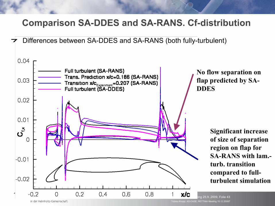
Comparison
SA-DDES and SA-RANS. Cf-distribution
Differences
between
SA-DDES and SA-RANS (both
fully-turbulent)
Significant
increase of size
of separation
region
on flap
for SA-RANS with
lam.-
turb. transition compared
to full-
turbulent
simulation
No flow
separation
on flap
predicted
by
SA-
DDES


