
International Journal on Electrical Engineering and Informatics ‐ Volume 4, Number 1, March 2012
A New Approach for Optimal Power Flow Solution Based on Two Step
Initialization with Multi-Line FACTS Device
A. V. Naresh Babu1 and S. Sivanagaraju2
1Dept. of EEE, DVR & Dr. HS MIC College of Technology, Kanchikacherla, Andhra Pradesh, India
2Dept. of EEE, University College of Engineering, JNTUK, Kakinada, Andhra Pradesh, India
Abstract: In this article, a new intelligent search evolution algorithm (ISEA) is proposed to minimize the generator fuel cost in optimal power flow (OPF) control with multi-line flexible alternating current transmission systems (FACTS) device which is interline power flow controller (IPFC). Unlike the OPF solution methods existing in the literature, in the proposed algorithm, a two step initialization process have been adopted which eliminates the mutation operation and also it gives optimal solution with less number of generations. The proposed algorithm has been examined and tested on a standard IEEE-30 bus system without and with IPFC. The test results indicate that the proposed algorithm with IPFC can obtain better solution than without IPFC. Keywords: Optimal power flow, optimization techniques, flexible alternating current transmission systems (FACTS) device, fuel cost minimization.
1. Introduction In recent years, with ever-increasing demand for electricity, the power transfer grows, the power system becomes increasingly more complex to operate and the system can become less secure for riding through the major outages. The electric companies are looking for ways to maximize the utilization of their existing transmission systems, therefore controlling the power flow in the transmission lines. There are emerging technologies available, which can help electric companies to deal with above problems. One of such technologies is FACTS device which is a recent development in high power electronics technology [1-3]. The interline power flow controller (IPFC) is a new member of FACTS controllers. Like the static synchronous compensator (STATCOM), static synchronous series compensator (SSSC) and unified power flow controller (UPFC), the IPFC also employs the voltage sourced converter as a basic building block. The UPFC and IPFC consists at least two converters. It is found that, in the past, much effort has been made in the modeling of the UPFC for power flow analysis [4-7]. However, UPFC aims to compensate a single transmission line, whereas the IPFC is conceived for the compensation and power flow management of multi-line transmission system. Further, it has been shown that the power injection model (PIM) of FACTS devices is a powerful model than other models [8, 9]. Ref. [10] presents a hybrid tabu search and simulated annealing approach to minimize the generator fuel cost in optimal power flow control with two types of FACTS devices namely, thyristor controlled series capacitor (TCSC) and thyristor controlled phase shifter (TCPS). A new optimal reactive power flow method is proposed to minimize the losses and to obtain best voltage profiles with unified power flow controller and also the fuzzy formulation of the problem is solved using an EP algorithm [11]. The optimal power flow problem with an explicit modeling of static var compensator (SVC) and unified power flow controller (UPFC) is presented for longitudinal systems [12]. Ref. [13] proposes a thyristor controlled series capacitor (TCSC) firing angle model for optimal power flow solution using Newton’s method. [14] Illustrates the use of evolutionary strategies to obtain the optimal values of control variables for the FACTS located power system. A differential evolution algorithm to minimize the generator fuel cost in optimal power Received: September 2nd, 2011. Accepted: April 9th, 2012
173
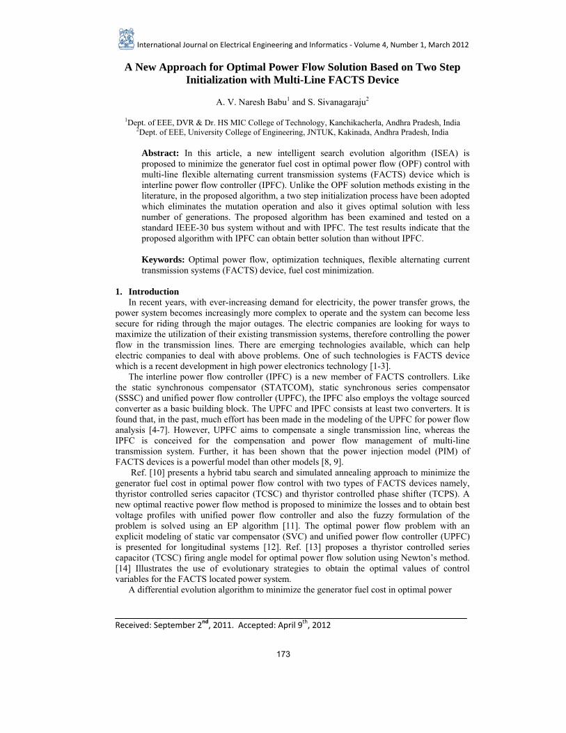
flow control with thyristor controlled series capacitor (TCSC) and thyristor controlled phase shifter (TCPS) has been presented [15]. A study of the implementation of the new load flow equations format in an optimal power flow program with UPFC based on extended conic quadratic (ECQ) format has been reported [16]. A multi objective non-linear optimization problem for secure bilateral transaction determination using AC distribution factors with UPFC in hybrid electricity markets have been discussed [17]. An efficient parallel GA for the solution of large-scale OPF problem with shunt FACTS devices has been presented [18]. Careful study of the former literature reveals that there is a single step initialization process along with mutation operation and single line FACTS device. But, in the proposed algorithm the initialization is done in two steps so that the mutation operation is not required and also it gives better solution with less number of generations. Further, a multi-line FACTS device which is IPFC has been used in this paper. The feasibility of the proposed algorithm is demonstrated for a standard IEEE-30 bus system without and with IPFC. The obtained OPF results are compared without and with IPFC. The results reveal that best solution obtained by the proposed algorithm with IPFC is quite encouraging and useful in optimal power flow environment. The rest of the paper is organized as follows: Section 2 explains the operating principle and power injection model of IPFC. Section 3 illustrates optimal power flow problem formulation with IPFC. Section 4 describes the proposed algorithm. Section 5 gives overall solution procedure. The effectiveness of proposed algorithm for optimal power flow solution through numerical example is presented in section 6 and finally, conclusions are given in section 7. 2. Multi-Line FACTS Device: Interline Power Flow Controller (IPFC) A. Operating Principle of IPFC In its general form the interline power flow controller employs a number of dc-to-ac converters each providing series compensation for a different line. In other words, the IPFC comprises a number of Static Synchronous Series Compensators (SSSC). The simplest IPFC consists of two back-to-back dc-to-ac converters, which are connected in series with two transmission lines through series coupling transformers and the dc terminals of the converters are connected together via a common dc link as shown in Figure1 [19, 20].With this IPFC, in addition to providing series reactive compensation, any converter can be controlled to supply real power to the common dc link from its own transmission line
Figure 1. Schematic diagram of two converter IPFC
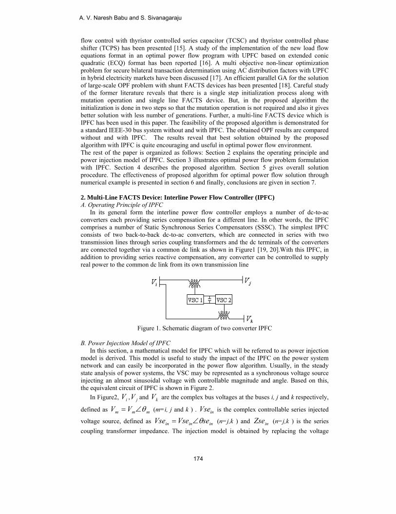
B. Power Injection Model of IPFC In this section, a mathematical model for IPFC which will be referred to as power injection model is derived. This model is useful to study the impact of the IPFC on the power system network and can easily be incorporated in the power flow algorithm. Usually, in the steady state analysis of power systems, the VSC may be represented as a synchronous voltage source injecting an almost sinusoidal voltage with controllable magnitude and angle. Based on this, the equivalent circuit of IPFC is shown in Figure 2. In Figure2, iV , jV and kV are the complex bus voltages at the buses i, j and k respectively,
defined as mmm VV θ∠= (m=i, j and k ) . inVse is the complex controllable series injected
voltage source, defined as ininin seVseVse θ∠= (n=j,k ) and inZse (n=j,k ) is the series coupling transformer impedance. The injection model is obtained by replacing the voltage
A. V. Naresh Babu and S. Sivanagaraju
174
source ( inVse ) as current source ( inIse ) in parallel with the transmission line. For the sake of simplicity, the resistance of the transmission lines and the series coupling transformers are neglected. Therefore, the current source can be expressed as
ininin VsejbseIse −= (1)
Figure 2. Equivalent circuit of two converter IPFC
Now, the current source ( inIse ) can be modeled as injection powers at the buses i, j and k. The complex power injected at ith bus is
( )∗=∑ −=
kjniniiinj IseVS
,,
(2)
Substitute (1) in (2)
( )∗=∑=
kjnininiiinj VsejbseVS
,,
(3)
After simplification, the active power and reactive power injections at ith bus are
( )∑
=
−==kjn
iniininiiinjiinj sebseVseVSP,
,, sin()Re( θθ (4)
( )∑
=
−−==kjn
iniininiiinjiinj sebseVseVSQ,
,, cos()Im( θθ (5)
The complex power injected at nth bus (n=j,k) is
( )∗= innninj IseVS , (6)
Substitute (1) in (6)
( )∗−= ininnninj VsejbseVS , (7) After simplification, the active power and reactive power injections at nth bus are
)sin()Re( ,, innininnninjninj sebseVseVSP θθ −−==
(8)
)cos()Im( ,, innininnninjninj sebseVseVSQ θθ −==
(9)
A New Approach for Optimal Power Flow Solution Based on Two Step
175
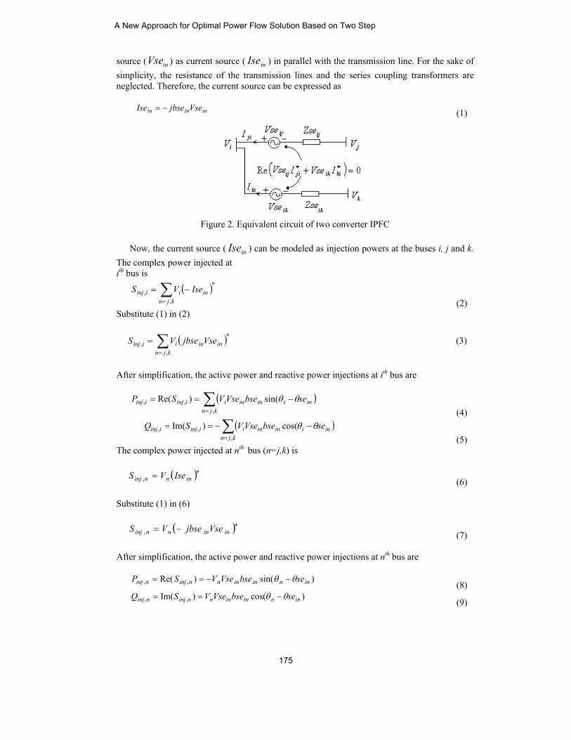
Based on (4), (5), (8), and (9), power injection model of IPFC can be seen as three dependent power injections at buses i, j and k as shown in Figure3.
Figure 3. Power injection model of two converter IPFC
As IPFC neither absorbs nor injects active power with respect to the ac system, the active power exchange between the converters via the dc link is zero, i.e.
( ) 0Re =+ ∗∗
kiikjiij IVseIVse (10)
Where the superscript * denotes the conjugate of a complex number. If the resistances of series transformers are neglected, (10) can be written as
∑=
=kjim
minjP,,
, 0 (11)
3. Formulation of the OPF Problem with IPFC In this article, minimization of fuel cost is considered as an objective function to examine the performance of the proposed algorithm without and with IPFC. The optimal solution must satisfy all the equality and inequality constraints. The OPF problem with IPFC is expressed as follows:
Min hcPbPang
iigiigii /$)(
1
2∑=
++ (12)
Subject to:
( ) 0cos ,
1
=++−−− ∑=
minjjiijijj
nb
jiii PYVVPdPg δδθ
(13)
( ) 0sin ,
1
=++−+− ∑=
minjjiijijj
nb
jiii QYVVQdQg δδθ (14)
ngiPgPgPg iii ,..,2,1maxmin =≤≤ (15)
ngiQgQgQg iii ,..,2,1maxmin =≤≤ (16)
nbiVVV iii ,..,2,1maxmin =≤≤ (17)
ntiTTT iii ,..,2,1maxmin =≤≤ (18)
A. V. Naresh Babu and S. Sivanagaraju
176
nciQcQcQc iii ,..,2,1maxmin =≤≤ (19)
maxmin VseVseVse ≤≤ (20)
maxmin sesese θθθ ≤≤ (21)
where iii cba &, are cost co-efficients of generator at bus i . ng is the number of generator buses.
ii QgPg & are the active and reactive power generations at thi bus.
ii QdPd & are the active and reactive power demand at thi bus. nb is the number of buses. ji VV & are the voltage magnitudes of thth ji & bus.
ji δδ & are the voltage angles of thth ji & bus.
ijijY θ& are the bus admittance matrix elements between thth ji & bus.
maxmin & ii PgPg are the minimum and maximum active power generation limits at thi bus.
maxmin & ii QgQg are the minimum and maximum reactive power generation limits at thi
bus. maxmin & ii VV are the minimum and maximum voltage limits at thi bus
maxmin & ii TT are the minimum and maximum tap settings of thi transformer .
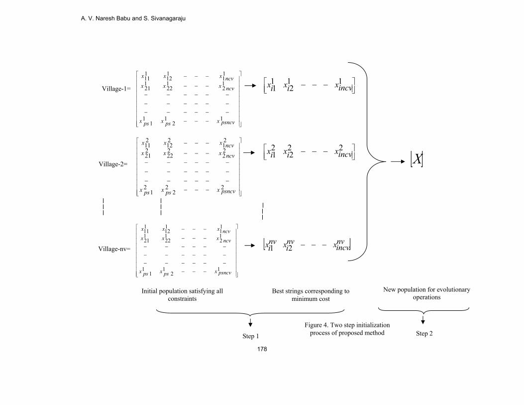
nt represents number of transformer tap settings. maxmin & ii QcQc are the minimum and maximum reactive power injection limits of thi compensator and nc represents number of compensators. 4. Intelligent Search Evolution Algorithm (ISEA) The intelligent search evolution algorithm tries to approach the target in an optimal manner for finding the optimal or near optimal solution to any mathematical optimization problem. The initial population is randomly generated with the control parameter limits in two steps. Then, the evolutionary operators like crossover or recombination and selection are performed to all individuals until a stopping criterion is reached. The major stages of the proposed algorithm are briefly described as follows: A. Two Step Initialization The population is generated by using the following equation
)()1,0( minmaxmin
, jjjji xxrandxx −+= (22) where psi ,..,2,1= and .,..,2,1 ncvj = ps = population size. ncv = number of control variables. maxmin & jj xx are the lower and upper bounds of thj control variable. rand ( 0,1 ) is a uniformly distributed random number between 0 and 1. In this article, a two step initialization process is adopted. The two step initialization process provides better probability of detecting an optimal solution to the power flow equations that would globally minimize a given objective function. In the first step, initial population is
A New Approach for Optimal Power Flow Solution Based on Two Step
177
New population for evolutionary operations
Best strings corresponding to minimum cost
Initial population satisfying all constraints
[ ]X
Step 1 Step 2 Figure 4. Two step initialization
process of proposed method
⎥⎥⎥⎥⎥⎥⎥⎥⎥⎥
⎦
⎤
⎢⎢⎢⎢⎢⎢⎢⎢⎢⎢
⎣
⎡
−−−−−−−−−−−−−−−−−−−−−
−−−
−−−
222
21
22
222
221
21
212
211
psncvxpsxpsx
ncvxxxncvxxx
⎥⎦⎤
⎢⎣⎡ −−− 11
211 incvxixix
⎥⎦⎤
⎢⎣⎡ −−− 22
221 incvxixix
⎥⎥⎥⎥⎥⎥⎥⎥⎥⎥
⎦
⎤
⎢⎢⎢⎢⎢⎢⎢⎢⎢⎢
⎣
⎡
−−−−−−−−−−−−−−−−−−−−−
−−−
−−−
112
11
12
122
121
11
112
111
psncvxpsxpsx
ncvxxxncvxxx
[ ]nvincvxnv
ixnvix −−−21
Village-2=
⎥⎥⎥⎥⎥⎥⎥⎥⎥⎥
⎦
⎤
⎢⎢⎢⎢⎢⎢⎢⎢⎢⎢
⎣
⎡
−−−−−−−−−−−−−−−−−−−−−
−−−
−−−
112
11
12
122
121
11
112
111
psncvxpsxpsx
ncvxxxncvxxx
Village-1=
Village-nv=
A. V. Naresh Babu and S. Sivanagaraju
178
generated as a multi-dimensional vector of size (ps × ncv) and it is considered as a village. All the control variables in the village must satisfy the constraints. Evaluate the value of cost function for each string in the village. Select the best string from the village corresponding to minimum cost. Repeat the procedure for number of villages (nv). In the second step, combine all the best strings from each village to form multi-dimensional vector [ ]X of size (nv ×ncv) and this new population is used for evolutionary operations. For clear reference, the two step initialization process is shown in Figure4. The superscript in Figure4 represents village number. B. Recombination In this study, an efficient recombination operator has been used so that search along
variables is also possible. If )( jix and )(k
ix are the values of variables ix in two strings j and k. The crossover between these two values may produce the following new value
)()()1( ki
ji
newi xxx λλ +−=
C. Selection For the present work, sorting and ranking selection procedure is used. D. Stopping Criteria In the current work, the number of generations reaches the given maximum number of generations is used as stopping criteria. 5. Intelligent Search Evolution Algorithm for OPF with IPFC The proposed algorithm procedure for OPF with IPFC is described as follows: Step 1: Read the system data and IPFC data. Choose population size, number of villages and maximum number of generations. Step 2: Generate a string corresponding to number of control variables using equation (22). Step 3: Run the Newton-Raphson load flow and check all the constraints. Step 4: If all the constraints are satisfied, find the cost .Then, store the cost and corresponding string. Otherwise, reject the string. Step 5: Repeat steps 2 to 4 for number of villages. Store the minimum cost and corresponding string from each village to form new population as shown in Figure4. Step 6: Perform recombination operation on new population using equation (23). Step 7: Run the Newton-Raphson load flow and check all the constraints. Step 8: If all the constraints are satisfied, find the cost .Then, store the cost and corresponding string. Otherwise, reject the string. Step 9: Stop the process, if the maximum number of generations is reached. Otherwise, go to step 6. 6. Results and Discussions In this section, a standard IEEE 30-bus system [21] has been considered to demonstrate the effectiveness and robustness of ISEA (proposed algorithm) without and with IPFC. In 30-bus test system, bus 1 is considered as slack bus, while bus 2,3,5,8,11 and 13 are taken as generator buses and other buses are load buses. A MATLAB program is implemented for the test system on a personal computer with Intel Pentium dual core 1.73 GHz processor and 512 MB RAM. Five runs have been performed for the test system. The optimal solution results over these five runs have been tabulated. The input parameters of ISEA for the test system are given in Table 1.
A New Approach for Optimal Power Flow Solution Based on Two Step
179
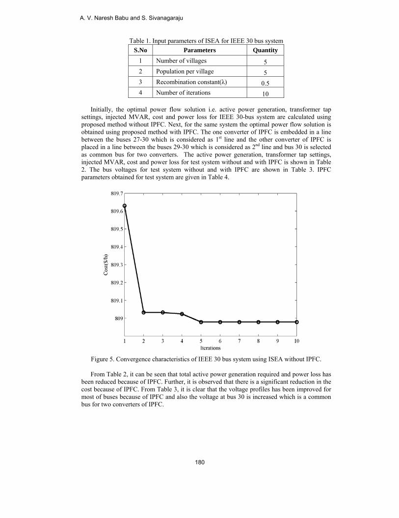
Table 1. Input parameters of ISEA for IEEE 30 bus system S.No Parameters Quantity
1 Number of villages 5 2 Population per village 5 3 Recombination constant(λ) 0.5 4 Number of iterations 10
Initially, the optimal power flow solution i.e. active power generation, transformer tap settings, injected MVAR, cost and power loss for IEEE 30-bus system are calculated using proposed method without IPFC. Next, for the same system the optimal power flow solution is obtained using proposed method with IPFC. The one converter of IPFC is embedded in a line between the buses 27-30 which is considered as 1st line and the other converter of IPFC is placed in a line between the buses 29-30 which is considered as 2nd line and bus 30 is selected as common bus for two converters. The active power generation, transformer tap settings, injected MVAR, cost and power loss for test system without and with IPFC is shown in Table 2. The bus voltages for test system without and with IPFC are shown in Table 3. IPFC parameters obtained for test system are given in Table 4.
Figure 5. Convergence characteristics of IEEE 30 bus system using ISEA without IPFC.
From Table 2, it can be seen that total active power generation required and power loss has been reduced because of IPFC. Further, it is observed that there is a significant reduction in the cost because of IPFC. From Table 3, it is clear that the voltage profiles has been improved for most of buses because of IPFC and also the voltage at bus 30 is increased which is a common bus for two converters of IPFC.
A. V. Naresh Babu and S. Sivanagaraju
180
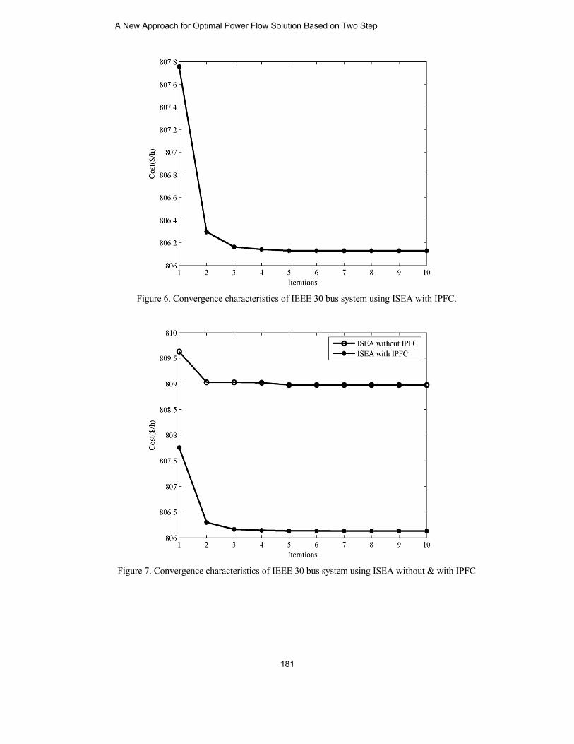
Figure 6. Convergence characteristics of IEEE 30 bus system using ISEA with IPFC.
Figure 7. Convergence characteristics of IEEE 30 bus system using ISEA without & with IPFC
A New Approach for Optimal Power Flow Solution Based on Two Step
181
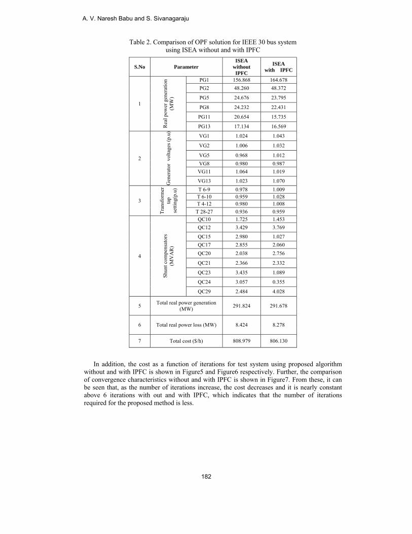
Table 2. Comparison of OPF solution for IEEE 30 bus system using ISEA without and with IPFC
S.No Parameter ISEA
without IPFC
ISEA with IPFC
1
Rea
l pow
er g
ener
atio
n
(MW
)
PG1 156.868 164.678 PG2 48.260 48.372
PG5 24.676 23.795
PG8 24.232 22.431
PG11 20.654 15.735
PG13 17.134 16.569
2
Gen
erat
or v
olta
ges (
p.u)
VG1 1.024 1.043
VG2 1.006 1.032
VG5 0.968 1.012 VG8 0.980 0.987 VG11 1.064 1.019
VG13 1.023 1.070
3
Tran
sfor
mer
ta
p se
tting
(p.u
) T 6-9 0.978 1.009 T 6-10 0.959 1.028 T 4-12 0.980 1.008 T 28-27 0.936 0.959
4
Shun
t com
pens
ator
s
(M
VA
R)
QC10 1.725 1.453 QC12 3.429 3.769
QC15 2.980 1.027 QC17 2.855 2.060 QC20 2.038 2.756
QC21 2.366 2.332
QC23 3.435 1.089
QC24 3.057 0.355
QC29 2.484 4.028
5 Total real power generation (MW) 291.824 291.678
6 Total real power loss (MW) 8.424 8.278
7 Total cost ($/h) 808.979 806.130
In addition, the cost as a function of iterations for test system using proposed algorithm without and with IPFC is shown in Figure5 and Figure6 respectively. Further, the comparison of convergence characteristics without and with IPFC is shown in Figure7. From these, it can be seen that, as the number of iterations increase, the cost decreases and it is nearly constant above 6 iterations with out and with IPFC, which indicates that the number of iterations required for the proposed method is less.
A. V. Naresh Babu and S. Sivanagaraju
182
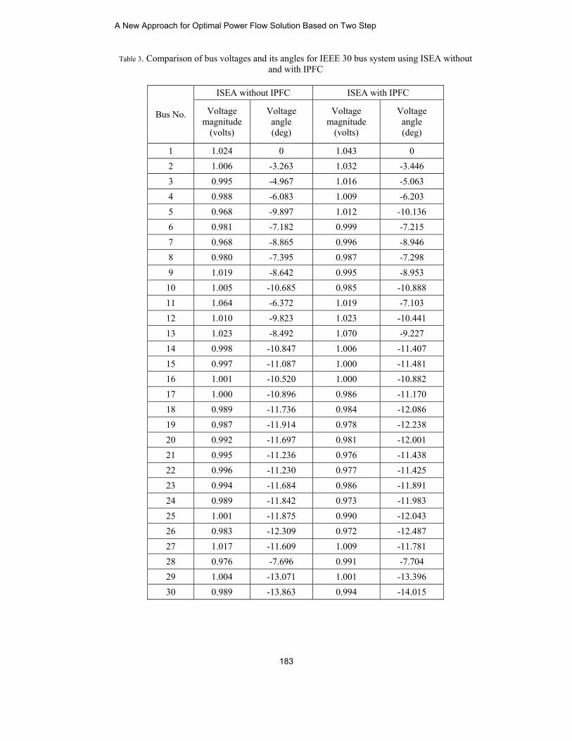
Table 3. Comparison of bus voltages and its angles for IEEE 30 bus system using ISEA without and with IPFC
Bus No.
ISEA without IPFC ISEA with IPFC
Voltage magnitude
(volts)
Voltage angle (deg)
Voltage magnitude
(volts)
Voltage angle (deg)
1 1.024 0 1.043 0 2 1.006 -3.263 1.032 -3.446 3 0.995 -4.967 1.016 -5.063 4 0.988 -6.083 1.009 -6.203 5 0.968 -9.897 1.012 -10.136 6 0.981 -7.182 0.999 -7.215 7 0.968 -8.865 0.996 -8.946 8 0.980 -7.395 0.987 -7.298 9 1.019 -8.642 0.995 -8.953
10 1.005 -10.685 0.985 -10.888 11 1.064 -6.372 1.019 -7.103 12 1.010 -9.823 1.023 -10.441 13 1.023 -8.492 1.070 -9.227 14 0.998 -10.847 1.006 -11.407 15 0.997 -11.087 1.000 -11.481 16 1.001 -10.520 1.000 -10.882 17 1.000 -10.896 0.986 -11.170 18 0.989 -11.736 0.984 -12.086 19 0.987 -11.914 0.978 -12.238 20 0.992 -11.697 0.981 -12.001 21 0.995 -11.236 0.976 -11.438 22 0.996 -11.230 0.977 -11.425 23 0.994 -11.684 0.986 -11.891 24 0.989 -11.842 0.973 -11.983 25 1.001 -11.875 0.990 -12.043 26 0.983 -12.309 0.972 -12.487 27 1.017 -11.609 1.009 -11.781 28 0.976 -7.696 0.991 -7.704 29 1.004 -13.071 1.001 -13.396 30 0.989 -13.863 0.994 -14.015
A New Approach for Optimal Power Flow Solution Based on Two Step
183
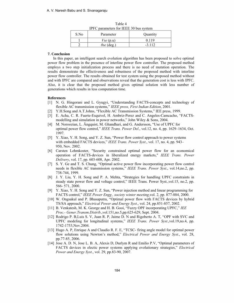
Table 4 IPFC parameters for IEEE 30 bus system
S.No Parameter Quantity 1 Vse (p.u) 0.119 2 θse (deg.) -3.112
7. Conclusion In this paper, an intelligent search evolution algorithm has been proposed to solve optimal power flow problem in the presence of interline power flow controller. The proposed method employs a two step initialization process and there is no need of mutation operation. The results demonstrate the effectiveness and robustness of the proposed method with interline power flow controller. The results obtained for test system using the proposed method without and with IPFC are compared and observations reveal that the generation cost is less with IPFC. Also, it is clear that the proposed method gives optimal solution with less number of generations which results in less computation time. References [1] N. G. Hingorani and L. Gyugyi, “Understanding FACTS-concepts and technology of
flexible AC transmission systems,” IEEE press, First Indian Edition, 2001. [2] Y.H.Song and A.T.Johns, “Flexible AC Transmission Systems,” IEE press, 1999. [3] E. Acha, C. R. Fuerte-Esquivel, H. Ambriz-Perez and C. Angeles-Camcacho, “FACTS-
modelling and simulation in power networks,” John Wiley & Sons, 2004. [4] M. Noroozian, L. Ängquist, M. Ghandhari, and G. Andersson, “Use of UPFC for
optimal power flow control,” IEEE Trans. Power Del., vol.12, no. 4, pp. 1629–1634, Oct. 1997.
[5] Y. Xiao, Y. H. Song, and Y. Z. Sun, “Power flow control approach to power systems with embedded FACTS devices,” IEEE Trans. Power Syst., vol. 17, no. 4, pp. 943– 950, Nov. 2002.
[6] Carsten Lehmkoster, "Security constrained optimal power flow for an economical operation of FACTS-devices in liberalized energy markets," IEEE Trans. Power Delivery, vol. 17, pp. 603-608, Apr. 2002.
[7] S. Y. Ge and T. S. Chung, “Optimal active power flow incorporating power flow control needs in flexible AC transmission systems,” IEEE Trans. Power Syst., vol.14,no.2, pp. 738-744, 1999.
[8] J. Y. Liu, Y. H. Song and P. A. Mehta, “Strategies for handling UPFC constraints in steady state power flow and voltage control,” IEEE Trans. Power Syst.,vol.15, no.2, pp. 566- 571, 2000.
[9] Y. Xiao, Y. H. Song and Y. Z. Sun, “Power injection method and linear programming for FACTS control,” IEEE Power Engg., society winter meeting,vol. 2, pp. 877-884, 2000.
[10] W. Ongsakul and P. Bhasaputra, “Optimal power flow with FACTS devices by hybrid TS/SA approach,” Electrical Power and Energy Syst., vol. 24, pp.851-857, 2002.
[11] B. Venkatesh, M. K. George and H. B. Gooi, “Fuzzy OPF incorporating UPFC,” IEE Proc.- Gener.Transm.Distrib.,vol.151,no.5,pp.625-629, Sept. 2004.
[12] Rodrigo P. B,Luis S. V, Juan R. P, Jaime D. N and Rigoberto A. T, “OPF with SVC and UPFC modeling for longitudinal systems,” IEEE Trans. Power Syst.,vol.19,no.4, pp. 1742-1753,Nov.2004.
[13] Hugo A. P, Enrique A and Claudio R. F. E, “TCSC- firing angle model for optimal power flow solutions using Newton’s method,” Electrical Power and Energy Syst., vol. 28, pp.77-85, 2006.
[14] Jose A. D. N, Jose L. B. A, Alexis D, Durlym R and Emilio P.V, “Optimal parameters of FACTS devices in electic power systems applying evolutionary strategies,” Electrical Power and Energy Syst., vol. 29, pp.83-90, 2007.
A. V. Naresh Babu and S. Sivanagaraju
184
[15] M.BElec
[16] RabiIEEE
[17] AshwbilatPow
[18] B. Mwith32, p
[19] A. VanalARP
[20] A. VinterIEEE
[21] IEEE
research iand Optim
received tpaper prizinterests Techniqu
Basu, “Optimactrical Power aih A. Jabr, “OE Trans. Powewani Kumar Steral transactio
wer ComponentMahdad, K. Srah shunt FACTSpp.507-517, 20V. Naresh Bablysis of a powPN Journal of EV. Naresh Baburline power floE- India Int. CE 30-bus syste
A. VenginM.TeKakinfrom NehruHe iselectr
interests includmization Techn
S. SenginM.Te(IIT),ElectrHydeseniorengin
two National aze award) frominclude FAC
ues.
al power flowand Energy SysOptimal powerer Syst., vol.23,S and S.Chananon determinatits and Systems,airi and T. BoS using efficien010. bu, S. Sivanag
wer system in tEngineering anu and S. Sivanaow controller(
Conf. on Power m data availab
V. Naresh Baeering from Rch in power sy
nada, Andhra Pthe departmen
u Technologicas currently Asonics engineerde FACTS conniques.
Sivanagarajuneering from ech in electrica, Khargpur, Wronics Enginee
erabad, Andhrar Associate Pr
neering at Jawawards (Panditm the Institute TS controllers
w with FACTst., vol. 30, pp.r flow using a, no.3, Aug.200na “New multiion with UPFC, vol. 36, pp. 5uktir “Optimalnt parallel GA
araju, Ch. Padthe presence ond Applied Scieagaraju, “MathIPFC) parameElectronics, N
ble at http://ww
abu received RVR & JC Cystems from JaPradesh, Indiant of electricaal University-Kssociate Profering at DVR &ntrollers, power
received hisAndhra Unival power syste
West Bengal, Iering from Jawa Pradesh, Indrofessor in the
waharlal Nehrut Madan Mohanof Engineers (s, Distribution
TS devices us150-156, 2008
an extended co08. i-objective optiC in hybrid e55-574, 2008.l power flow f
A,” Electrical P
dmanabharaju of interline poences, vol.5, nohematical modeeters in power New Delhi, Indiww.ee.washingt
his B.Tech inCE, Andhra Prawaharlal Nehra, in 2007. Heal and electronKakinada.ssor in the d
&Dr. HS MIC r electronics ap
B.Tech in versity, Andhrems from IndIndia in 2000 waharlal Nehruia in 2004. Dre department u Technologicn Malaviya me
(India) for the n Systems au
sing differenti8. onic quadratic
imization probelectricity mark
for large scale Power and Ene
and T.Ramanaower flow conto.10,pp.1-4, Oelling, analysisflow studies,”
ia, Jan. 2011. ton.edu/researc
n electrical anradesh, India,ru Technologice is currently pnics engineerin
department of College of Te
pplications to p
electrical anra Pradesh, Indian Institute o
and Ph.D in ru Technologicr.S.Sivanagarajof electrical a
cal University-emorial prize ayear 2003-200
utomation and
ial evolution,”
c formulation,”
blem for securekets,” Electric
power systemergy Syst., vol.
a “Power flowtroller(IPFC),”ct. 2010. s and effects of” Proc. of 4th
ch/pstca.
nd electronics, in 2003 andcal University-pursuing Ph.Dng, Jawaharlal
electrical andechnology. Hispower systems
nd electronicsndia in 1998,of TechnologyElectrical and
cal University-aju is currentlyand electronics-Kakinada. Heaward and best04.His researchd Optimization
”
”
e c
m .
w ”
f h
s d -
D l
d s s
s ,
y d -y s e t h n
A New Approach for Optimal Power Flow Solution Based on Two Step
185


