

A New Lamb-Wave Based NDT System for Detection and Identification of
Defects in Composites
Wei LIN, Lay Siong GOH, B. Stephen WONG
1
Singapore Institute of Manufacturing Technology, 71 Nanyang Drive, Singapore 638075 1School of Mechanical and Aerospace Engineering, Nanyang Technical University, Singapore
Corresponding author: [email protected]
Abstract
Ultrasonic testing is one of the most applied and powerful method for inspecting carbon fibre
reinforced polymers (CFRP) for wide range of internal defects. For sandwich composites, pitch-catch
technique, that utilise guided (Lamb) wave are most effective in detecting the common defects such as
crushed cores, disbond and delamination. Popular commercial instrument could detect the presence of
these defects but it is not able to give crucial information about the defects, which include types of the
defects, the exact location of the defects, and the depth of the delamination. This information will be
important for determining if and how the composite repair can be carried out. Conventional
instrument gives yes or no result. In this paper, we present an enhanced Lamb wave based method
which not only able to detect the defect but also able to distinguish different types of defects in the
sandwich composites. The key novelty in our method is a modified excitation signal designed for
address the dispersion effect in the low frequency range. The response to the material was based on
phase shift against the excitation signal. The approach was implemented in a portable system that
comes with a special probe. This probe, embedded with a position sensor, can directly scan on the
composite surface to obtain and record C-scan type of defect map without using an x-y stage.
Keywords: Ultrasonic Testing, Lamb Waves, CFRP, Inspection
1. Introduction
As composites are being increasingly used in commercial aircrafts, new inspection technologies have
to be developed to meet the industry demands for airworthiness and flight safety. Examples of the
commonly found defects in composite materials include delaminations, disbond, crushed core, and
heat damage. In the case of delaminations, there is a separation between one ply to another, which can
be caused by improper construction of the laminate or from heat exposure. A composite structure can
also be found in laminate-core-laminate form, whose core is made of fibreglass or Nomex in a
honeycomb shape. The adhesive between the laminates and the core can also be improperly applied or
damaged from various conditions, which causes the laminate layers to be disbonded from the core.
This condition can clearly cause a loss of strength of the structure. In another form of internal defect,
a crushed core can happen when the aircraft structure is hit by an object. However, this damage
cannot be seen from the outside and therefore an inspection process that can penetrate the depth of the
core is desirable.
A fast inspection technique is a so called “coin tap” testing method, which the inspection conductor
tap the suspected areas lightly with a hard and blunt tool to obtain an indications of the underlying
structure from the sound of the tap [1]. Other methods include thermograph, non-linear spectroscopy,
X-radiography, and eddy current measurements, and ultrasonic waves. Among these techniques
Lamb wave methods have recently re-emerged as a reliable way to locate damage in the composite
SINCE2013Singapore International NDT Conference & Exhibition 2013, 19-20 July 2013

components [2]. Current commercial instrument utilizes Lamb wave could detect the presence of
these defects but it is not able to give crucial information about the defects, which include types of the
defects, the exact location of the defects, and the depth of the delamination. This information will be
important for determining if and how the composite repair can be carried out. In the following
sessions we present an enhanced Lamb wave based method which not only able to detect the defect
but also able to distinguish different types of defects in the sandwich composites.
2. Theoretical Background
Lamb waves are guided waves which propagate in thin structures such as plates. They interact with
the boundaries by way of reflection and refraction in the combination of longitudinal and shear waves.
Lamb wave can either by symmetric or anti-symmetric depends on plate thickness, phase velocity,
wave numbers. The characteristic equations of the two modes [3] can be expressed in Equations (1)
and (2).
tan��ℎ�
tan��ℎ�=
4����
��� − ���� for symmetric modes (1)
tan��ℎ�
tan��ℎ�=��� − ����
4���� for anti-symmetric modes (2)
In these equations, �� =
��
���− �� �� =
��
���− �� � =
�
��
where �� is the velocity of longitudinal modes, �� is the velocity of the transverse mode, �� is the
phase velocity, k is the wave number, ω is the wave circular frequency of the propagating wave and h
is plate thickness.
Solving these two equations with known material properties gives the dispersion curves, which is a
plot of phase velocity against frequency or frequency-thickness. The dispersion curves can be used to
explore the various wave modes that are expected for a given excitation frequency and material
thickness. In a Lamb wave, at least two wave modes can be observed; the symmetrical mode S0 and
the asymmetrical mode A0 as illustrated in
Figure 1.
The dispersion curves illustrate two
distinct velocity dispersion characteristics
of Lamb waves. Firstly, the velocity
dispersion in a single mode is due to the
frequency dependency of a single Lamb
wave mode. Different frequency
components in a single Lamb wave mode
travel at different speeds, thus the wave
packet spreads as it propagates. Secondly,
the velocity dispersion among multiple
modes exists due to different modes
travelling at different speeds at each given
frequency [4].
The Lamb wave inspection method is very promising for the detection of defects in the composites. In
conventional ultrasonic methods based on the reflection or scattering by defects, the smallest defect
detectable is dependent on the wavelength. Low frequencies are incapable of detecting small defects,
while high frequency signals have high attenuation. On the other hand, the defect detection capability
of the Lamb wave inspection method does not simply depend on the reflection of waves by the defects,
0.0 1.0 2.0 3.0
0.0
2.0
4.0
6.0
8.0
10.0
Frequency (MHz)
Vp
h (
m/m
s)
S0
Figure 1. Example of dispersion curves on 3mm thickness
aluminium plate
A0
but also on the interaction between the waves and the defects. The presence of a defect changes the
peak amplitude corresponding to a particular Lamb wave mode, which is typically exploited in the
popular Lamb wave based NDT tools, and also may cause frequency shift of the wave [5].
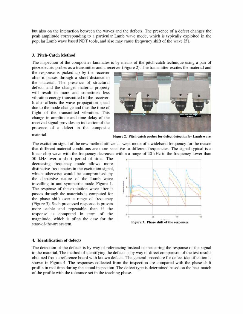
3. Pitch-Catch Method
The inspection of the composites laminates is by means of the pitch-catch technique using a pair of
piezoelectric probes as a transmitter and a receiver (Figure 2). The transmitter excites the material and
the response is picked up by the receiver
after it passes through a short distance in
the material. The presence of structural
defects and the changes material property
will result in more and sometimes less
vibration energy transmitted to the receiver.
It also affects the wave propagation speed
due to the mode change and thus the time of
flight of the transmitted vibration. This
change in amplitude and time delay of the
received signal provides an indication of the
presence of a defect in the composite
material.
The excitation signal of the new method utilizes a swept mode of a wideband frequency for the reason
that different material conditions are more sensitive to different frequencies. The signal typical is a
linear chip wave with the frequency decreases within a range of 40 kHz in the frequency lower than
50 kHz over a short period of time. The
decreasing frequency mode allows more
distinctive frequencies in the excitation signal,
which otherwise would be compromised by
the dispersive nature of the Lamb wave
travelling in anti-symmetric mode Figure 1.
The response of the excitation wave after it
passes through the materials is computed for
the phase shift over a range of frequency
(Figure 3). Such processed response is proven
more stable and repeatable than if the
response is computed in term of the
magnitude, which is often the case for the
state-of-the-art system.
4. Identification of defects
The detection of the defects is by way of referencing instead of measuring the response of the signal
to the material. The method of identifying the defects is by way of direct comparison of the test results
obtained from a reference board with known defects. The general procedure for defect identification is
shown in Figure 4. The responses collected from the inspection are compared with the phase shift
profile in real time during the actual inspection. The defect type is determined based on the best match
of the profile with the tolerance set in the teaching phase.
Figure 2. Pitch-catch probes for defect detection by Lamb wave
Figure 3. Phase shift of the responses

Figure 4. General operational steps for defect identifications
The methods described above have been
(Figure 5). It consists of a laptop, a DAQ unit
transmitter. With PiCaScanner, the inspection area can
position transducer attached on the aircraft surface
5. Demonstration
Test Samples
One of the test specimen used is an
standards set by the Commercial Aircraft Composite Repair Committee (CACRC
called Composite Honeycomb Reference Standards (CHRS) is made of laminates lay up on both sides
of the honeycomb core. The laminate material is either glass fibre or carbon fibre fab
every panel consists of two types of materials
with different laminate thickness ranging from 3 to 12 plies.
fibre laminates panel.
Four types of defects are artificially fabricated into the spe
machined core in which a flat bottom
pillow insert in which a layer of tissue are held together between two layers of polyamide film tape
and inserted into the interface layer.
a cross-section of the panel.
Figure 5. PiCaScanner is a NDT system that
allows the user manually scan the area of interest
for defects
. General operational steps for defect identifications
have been implemented in a portable system called PiCaScann
consists of a laptop, a DAQ unit and a pitch-catch probe embedded with a
he inspection area can be defined before the actual inspection u
osition transducer attached on the aircraft surface and the inspection probe imbedded with a position
encoder/sensor the actual inspection area on the aircraft
is mapped on to the screen of the NDT system
position transducer and encoder allow the linear
coordinates of the probe relative to a defined frame on
the aircraft surface to be determined. The area is then
gridded with a user-chosen numbers of uniform rows
and columns to form the display panel. Each of the grid
boxes is to display the inspection result of the
corresponding points on the actual aircraft surface. In
the actual inspection operation, the user scans the
inspection area with the probe and the processed results
are displayed bit by bit in the grid boxes. The results of
the inspections are illustrated wit
corresponding to the defect types assigned during the
teaching stage.
an inch thick carbon fiber honeycomb panel manufactured to the
standards set by the Commercial Aircraft Composite Repair Committee (CACRC) [6
called Composite Honeycomb Reference Standards (CHRS) is made of laminates lay up on both sides
e laminate material is either glass fibre or carbon fibre fabric. The core of
every panel consists of two types of materials namely Nomex and fibreglass. The CHRS panels come
with different laminate thickness ranging from 3 to 12 plies. Figure 6(a) shows an example of carbon
Four types of defects are artificially fabricated into the specimen (Figure 6(b)). Th
ed core in which a flat bottom hole of about 0.25 inch milled out of the honeycomb core
of tissue are held together between two layers of polyamide film tape
and inserted into the interface layer. Figure 6(c) shows a schematic diagram of the defects depicted in
PiCaScanner is a NDT system that
the area of interest
called PiCaScanner
embedded with a position
d before the actual inspection using a
and the inspection probe imbedded with a position
the actual inspection area on the aircraft
is mapped on to the screen of the NDT system. The
position transducer and encoder allow the linear
coordinates of the probe relative to a defined frame on
the aircraft surface to be determined. The area is then
chosen numbers of uniform rows
display panel. Each of the grid
boxes is to display the inspection result of the
corresponding points on the actual aircraft surface. In
the actual inspection operation, the user scans the
inspection area with the probe and the processed results
ayed bit by bit in the grid boxes. The results of
the inspections are illustrated with colours
corresponding to the defect types assigned during the
fiber honeycomb panel manufactured to the
6]. The panels,
called Composite Honeycomb Reference Standards (CHRS) is made of laminates lay up on both sides
ric. The core of
. The CHRS panels come
(a) shows an example of carbon
These include a
d out of the honeycomb core, a
of tissue are held together between two layers of polyamide film tape
schematic diagram of the defects depicted in
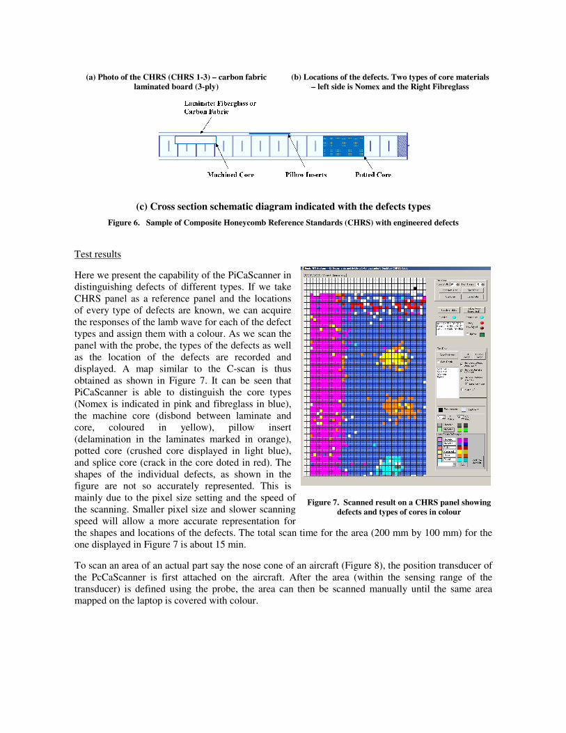
(a) Photo of the CHRS (CHRS 1-3) – carbon fabric
laminated board (3-ply)
(c) Cross section schematic diagram indicated with the defects types
Figure 6. Sample of Composite Honeycomb Reference Standards (CHRS) with engineered defects
Test results
Here we present the capability of the
distinguishing defects of different types.
CHRS panel as a reference panel and the
of every type of defects are known
the responses of the lamb wave for each of the defect
types and assign them with a colour
panel with the probe, the types of the defects as well
as the location of the defects are
displayed. A map similar to the C
obtained as shown in Figure 7. It can be seen that
PiCaScanner is able to distinguish
(Nomex is indicated in pink and fibreglas
the machine core (disbond between lamin
core, coloured in yellow), pillow inser
(delamination in the laminates marked
potted core (crushed core displayed
and splice core (crack in the core doted
shapes of the individual defects, as shown in the
figure are not so accurately represe
mainly due to the pixel size setting
the scanning. Smaller pixel size and slower scanning
speed will allow a more accurate
the shapes and locations of the defects.
one displayed in Figure 7 is about 1
To scan an area of an actual part say the
the PcCaScanner is first attached on the aircraft. After the area (within the sensing range of the
transducer) is defined using the probe, the area can then be scanned manually until the same area
mapped on the laptop is covered with colour.
carbon fabric
(b) Locations of the defects. Two types of core materials
– left side is Nomex and the Right
Cross section schematic diagram indicated with the defects types
. Sample of Composite Honeycomb Reference Standards (CHRS) with engineered defects
the PiCaScanner in
defects of different types. If we take
CHRS panel as a reference panel and the locations
of every type of defects are known, we can acquire
the responses of the lamb wave for each of the defect
types and assign them with a colour. As we scan the
panel with the probe, the types of the defects as well
of the defects are recorded and
to the C-scan is thus
. It can be seen that
uish the core types
fibreglass in blue),
machine core (disbond between laminate and
, pillow insert
marked in orange),
displayed in light blue),
doted in red). The
fects, as shown in the
not so accurately represented. This is
ting and the speed of
the scanning. Smaller pixel size and slower scanning
accurate representation for
shapes and locations of the defects. The total scan time for the area (200 mm by 10
15 min.
say the nose cone of an aircraft (Figure 8), the position
the PcCaScanner is first attached on the aircraft. After the area (within the sensing range of the
is defined using the probe, the area can then be scanned manually until the same area
mapped on the laptop is covered with colour.
Figure 7. Scanned result on a CHRS panel showing
defects and types of cores in colour
Two types of core materials
and the Right Fibreglass
. Sample of Composite Honeycomb Reference Standards (CHRS) with engineered defects
mm by 100 mm) for the
, the position transducer of
the PcCaScanner is first attached on the aircraft. After the area (within the sensing range of the
is defined using the probe, the area can then be scanned manually until the same area
. Scanned result on a CHRS panel showing
defects and types of cores in colour

Figure 8. Inspection of an aircraft nose cone using PiCaScanner
6. Conclusions
An enhanced Lamb-wave based method has been developed. It is able to detect and distinguish the
types of typical defects in the honeycomb composites, including the delaminations, disbonds, crushed
core, and crack. The method is implemented in a potable NDT system which comes with position
transducer. With it, the area of interests can be rapidly scanned and the defects information recorded
without the need of setting up an x-y stage on the areas of inspections. The development of the easy-
to-use system is able to provide more information about the material conditions which would allow
better decision making in the repair and maintenance operations.
7. Acknowledgements
The authors gratefully acknowledge the support from the Aerospace Programme, A*STAR, Singapore.
References
[1] P. Cawley and R.D. Adams The Mechanics of the Coin Tap Method of Non-Destructive Testing,
Journal of Sound and Vibration, 122 (1988), 299-316.
[2] Z. Su, L. Ye, Y. Lu, “Guided Lamb waves for identification of damage in composite structure: A
Review,” Journal of Sound and Vibration, 295 (2006) 753-780
[3] J.L. Rose, Ultrasonic Waves in Solid Media, Cambridge University Press, New York, 1999.
[4] Park, H. W., Kim, S. B., & Sohn, H., Understanding a time reversal process in Lamb wave
propagation, Wave Motion, 46(7), (2009).
[5] Kundu, T., Recent Advances of the Use Of Lamb Waves for Material Characterization, in
IUTAM Symposium on Mechanical Waves for Composte Stucures Characterisation, (2001) pp.
83-98.
[6] Composite Honeycomb NDI Reference Standard, ARP5606.


