

A NEW SIMPLIFIED CLOSED-FORM INTERACTION FORMULATIONS
FOR EVALUATION OF STRUCTURAL RESPONSE OF STIFFENED PLATES 41
Sayı 11, 2018 GiDB|DERGi
A NEW SIMPLIFIED CLOSED-FORM INTERACTION FORMULATIONS FOR EVALUATION OF STRUCTURAL
RESPONSE OF STIFFENED PLATES
Özgür ÖZGÜÇ*
*Istanbul Technical University, Dept. Of Naval Arch. and Ocean Engineering
ABSTRACT
A semi-analytical model for ultimate strength capacity assessment of stiffened plates has been
developed based on ANSYS non-linear elasto-plastic buckling analyses of a wide range of
typical ship panel geometries. The primary aim of the present study is to investigate the ultimate
strength interaction relationship of a stiffened plate subject to combine loads with imperfections
in the form of geometric deflections and welding induced residual stresses. The accuracy of the
interaction relationship is confirmed by use of inelastic finite element calculations. Comparison
is performed with existing ship rules used by Classification Societies as well. The results and
insights derived from the present work are summarized in great detail.
Keywords: Finite Element Analysis; Initial Imperfection; Interaction Formulas; Ship Hull; Ultimate
Strength
1. Introduction
Stiffened plates is the main structural building block in ship hulls and their structural response
subject to combine loads is a topic of significant practical interest in ship design. Figure 1 shows
an example of such construction where the stiffened plate spans between girders. For the real
ship structural stiffened plates, the most general loading case is a combination of longitudinal
stress, transverse stress, shear stress and lateral pressure. Due to the presence of the combine
loads, stiffened panels are susceptible to failure by instability. Instability of stiffened plates can
take one of fours forms [1,4,5,7] such as plate induced overall buckling (PI), stiffener induced
overall buckling (SI), plate buckling (PB) and stiffener tripping (ST). The typical buckling
modes are demonstrated in Figure 2.
R y s . 1 . 1 . P a n e l i p ³ y t a w k o n s t r u k c j i o k r ê t o w e j
p a n e l
p la t in g
p la te
tr a n s v . g ir d e r s
s t if fe n e r s
lo n g . g ir d e r s
Figure 1. A stiffened steel plate in ship hull
Precise modelling of stiffened panels can be achieved by means of analysis tools and computing
power. Initial imperfections such as welding induced residual stress and initial deflections of the
cross section can be explicitly incorporated into numerical models. In a series of recent papers,

42 Ö. ÖZGÜÇ
GiDB|DERGi Sayı 11, 2018
Grondin [3,4] considered the behaviour of these elements under axial compression, both
experimentally and numerically. The goal of that study was to investigate the tripping failure
mode and validate with experiments, a sophisticated non-linear finite element model that would
allow a more extensive study of the behaviour to be conducted numerically.
(a)
(b)
(c)
(d)
Figure 2. Typical buckling modes, (a) Overall buckling (plate induced); (b) overall buckling (stiffener induced); (c) plate buckling; and (d) stiffener tripping
Hughes, Ghosh and Chen [6] derived modified expressions for elastic local plate buckling and
overall panel buckling expressions form 55 Abaqus eigenvalue buckling analyses. Inelastic
RISK analysis for the ultimate collapse stress and post collapse behaviour using Abaqus Fem
was conducted on their models. Ultimate stress was also calculated using Orthotropic methods.
It was found that for panels having crossover proportions, Orthotropic based methods are
unsatisfactory. A direct calculation model (PULS) for determination of ultimate capacity of
stiffened panels was developed using energy principles and nonlinear plate theory according to
Marguerre and Von Karman [9]. Extensive verifications were carried out by means of Abaqus
FE program. In general, very satisfactory correspondence between PULS and more advanced
numerical programs were found.
Ozguc Et al. [13] developed the new simple design equations for predicting the ultimate
compressive strength of stiffened plates with initial imperfections in the form of welding-
induced residual stresses and geometric deflections were developed in this study. A non-linear
finite element method was used to investigate on 60 ANSYS elastic–plastic buckling analyses

A NEW SIMPLIFIED CLOSED-FORM INTERACTION FORMULATIONS
FOR EVALUATION OF STRUCTURAL RESPONSE OF STIFFENED PLATES 43
Sayı 11, 2018 GiDB|DERGi
of a wide range of typical ship panel geometries. Reduction factors of the ultimate strength are
produced from the results of 60 ANSYS inelastic finite element analyses. The accuracy of the
proposed equations was validated by the experimental results. Comparisons show that the
adopted method has sufficient accuracy for practical applications in ship design.
Paik Et al. [14] concentrated on methods for the ultimate limit state assessment of stiffened plate
structures under combined biaxial compression and lateral pressure actions considering the
bottom part of an AFRAMAX-class hypothetical double-hull oil tanker structure. Three
methods, namely ANSYS nonlinear finite element method, DNV PULS method, and
ALPS/ULSAP method were used.
Chaithanya Et al.. [11] evaluated the behavior of stiffened plates with different distortion levels
in order to address a rational structural design procedure, as pre-existing and fabrication-related
initial geometrical distortion from a structural design point of view. Non-linear finite element
(FE) analysis using ABAQUS was carried out under axial loading condition to predict the
behavior and the buckling strength.
Xu and Soares [12] simulated numerically the behavior of stiffened panels under uniaxial
compression until collapse and beyond, and then compared with tests made to investigate the
influence of the stiffener’s geometry and the boundary conditions. The stiffened panel models
have three longitudinal bays to produce reasonable boundary conditions in the longitudinal
direction. The material and geometric nonlinearities were accounted for in the FE analyses. The
initial geometric imperfections, which affect significantly the collapse behavior of stiffened
panels, were assumed to have the shape of the linear buckling mode. Four types of stiffeners
were made of mild or high tensile steel for bar stiffeners and mild steel for ‘L’ and ‘U’ stiffeners
to investigate different material and geometry configurations, and four boundary conditions
were analyzed.
Tekgoz Et al. [15] analyzed the effect of different finite element models on the ultimate strength
assessment of stiffened plates, where the effect of element size, and type, boundary conditions,
shape of initial imperfection, thickness and net sectional configurations were accounted for.
Four different finite element models and different structural configurations were compared to
the solution described by the Common Structural Rules (CSR).
Cho Et al. [16] proposed ultimate strength formulation for stiffened plates. The formulation was
derived by a regression study using the parametric study results. The accuracy and reliability of
the proposed formulation were compared with those of commercial packages, such as ABAQUS
and DNV PULS, and experimental results.
Zhang [17] presented a review and study on ultimate strength analysis methods for steel plates
and stiffened panels in axial compression. Buckling and collapsing mechanisms of steel plates
and stiffened panels are described. A study and further validation on the authors developed
formula for ultimate strength of stiffened panels using a comprehensive non-linear finite
element analysis, 110 models in total, and a wide range of model test results, 70 models in total,
were carried out. Finally, applications of the developed formula to existing oil tankers and bulk
carriers were presented.
The primary aim of the present study is to investigate the ultimate strength interaction
relationship of a stiffened plate subject to combine loads with imperfections in the form of

44 Ö. ÖZGÜÇ
GiDB|DERGi Sayı 11, 2018
geometric deflections and welding-induced residual stresses. The accuracy of the interaction
relationship is confirmed by use of inelastic finite element calculations. Comparison is
performed with existing ship rules used by Classification Societies as well. The results and
insights derived from the present work are summarized. 2. Simplified Closed-Form Formulations for Collapse Strength
A semi-analytical model for calculating the values of the critical buckling stresses for the plate,
beam-column, torsional-flexural (tripping) and local failure modes are developed with reduction
factors which can describes initial imperfections in the form of geometric deflections and
welding-induced residual stresses. Based on extensive numerical calculations an interaction
formula is proposed for combine loading which involves longitudinal compression, transverse
compression, shear loading and lateral pressure loading [8].
2.1 Elasto-plastic Collapse of the Structural Elements
The equation describing the load-end shortening curve or the elastic-plastic collapse of
structural elements composing the hull girder transverse section can be obtained from the
following formula, valid for both positive (shortening) and negative (lengthening) strains.
o (1)
where, is edge function, o is yield stress of element.
11
11
11
for
for
for
(2)
2.2 Beam – column Buckling Failure Model
The equation describing the load-end shortening curve 1CR for the beam-column buckling
of the stiffeners composing the hull girder transverse section can be obtained from the following
formula:
btSA
tEbSA
CCR 11 (3)
where, is edge function defined in equation 1, 1C is critical stress in MPa, SA is net
sectional area of a stiffener and b is spacing of stiffeners.

A NEW SIMPLIFIED CLOSED-FORM INTERACTION FORMULATIONS
FOR EVALUATION OF STRUCTURAL RESPONSE OF STIFFENED PLATES 45
Sayı 11, 2018 GiDB|DERGi
21
141
21
1
1o
Efor
E
oo
oEfor
E
C (4)
where 1C is based on the Johnson-Ostenfeld formulation accounting for inelastic effects on
the column’s buckling. In equation (3) the second term computes the loss of efficiency of plate
due to compression loading. Effective width, Eb , based on the Frankland`s approach developed
to the plate strength and given by,
25.391.1
25.325.12
25.125.2
25.1
Eforb
E
Eforb
EE
Eforb
Eb
(5)
where, 1E is Euler column buckling stress, which is calculated as below,
2
21
aEA
EIEE (6)
where, EI is net moment of inertia of ordinary stiffeners with attached shell plating of width
1Eb , EA is net sectional area of stiffeners with attached shell plating of effective width Eb , and
a is length of stiffened plate.
1
1
1
Eforb
Efor
E
b
Eb
(7)

46 Ö. ÖZGÜÇ
GiDB|DERGi Sayı 11, 2018
where, E
o
t
b
E
is defined.
2.3 Plate induced buckling failure mode
The equation describing the load-end shortening curve 2CR for the plate buckling
composing the hull girder transverse section can be obtained the following formula:
btSA
tEbSA
CR 2 (8)
2.4 Flexural – torsional (tripping) Buckling Failure Mode
The equation describing the load-end shortening curve 3CR for the flexural – torsional
(tripping) buckling of stiffeners composing the hull girder transverse can be obtained according
to following formula:
btA
btA
S
CPCS
CR
3
3 (9)
where, 3C is defined as critical stress.
23
341
23
3
3o
Efor
E
oo
oEfor
E
C (10)
where, 3E is Euler torsional buckling stress, defined as follows.
PI
tIEm
m
CK
aPI
WEI
E 385.02
22
2
3
(11)

A NEW SIMPLIFIED CLOSED-FORM INTERACTION FORMULATIONS
FOR EVALUATION OF STRUCTURAL RESPONSE OF STIFFENED PLATES 47
Sayı 11, 2018 GiDB|DERGi
where, WI
is net sectional moment of inertia of the stiffener about its connection to the attached
plating and is defined as follows.
tionsbulbandanglesforwhfbwtwhwhfbfbft
whfb
whfb
tionsTforwhfbft
barsflatforwtwh
WI
sec32
422
2)(12
23
sec12
23
36
33
(12)
where, PI is net polar moment of inertia of the stiffener about its connection to the attached
plating, defined as follows.
platefacewithstiffenersforftfbwhwtwh
barsflatforwtwh
PI
2
3
3
3
3
(13)
where, tI
is St. Venant’s net moment of inertia of stiffener without attached plating, defined as
follows:
platefacewithstiffenersforb
ttbth
barsflatforth
I
f
f
ffww
ww
t
63.013
1
3
33
3
(14)
where, m is number of half waves, may be taken equal to the integer number and CK
is
torsional buckling of axially loaded stiffeners, calculated by following;

48 Ö. ÖZGÜÇ
GiDB|DERGi Sayı 11, 2018
2222)1()1( mmKmm
C and
W
C
EI
aCK
4
4
0
(15)
where,0
C is a spring stiffener of the attached plating and can be expressed as follows,
b
EtC
73.2
3
0 (16)
Table 1. Torsional buckling of axially loaded stiffeners – Number of m half waves.
CK 40
CK 364
CK 14436
CK
m 1 2 3
where, CP
is buckling stress of attached plating, which can be determined by following
formula.
25.391.1
25.325.125.125.2
25.1
2
Eo
E
Eo
EE
Eo
CP
for
for
for
(17)
2.5 Web Local Buckling Failure Mode
The equating describing the load-end shortening curve
4CR for the web local buckling of
flanged stiffeners composing the hull girder transverse section can be obtained from the
following formula.
ffww
ffwweE
oCR
tbthbt
tbthtb
4 (18)
where, weh
is effective height of the web, which can be determined by following formula:

A NEW SIMPLIFIED CLOSED-FORM INTERACTION FORMULATIONS
FOR EVALUATION OF STRUCTURAL RESPONSE OF STIFFENED PLATES 49
Sayı 11, 2018 GiDB|DERGi
25.391.1
25.325.125.125.2
25.1
2
Ww
E
Ww
EE
Ww
we
forh
forh
forh
h
(19)
Et
ho
w
w
W
is defined while is relative strain.
Effective width, Eb is multiplied by reduction factors so as to introduce initial imperfections for
stiffened plates, namely,
qyrdEERRRRRbb
`
(20)
where `
Eb
is the effective width of imperfect stiffened plate, Eb is the effective width of perfect
stiffened plate, dR
is a reduction factor due to initial deflection, rR
is a reduction factor due to
welding-induced residual stress, yR
is a reduction factor due to bi-axial compression, R
is a
reduction factor due to shear stress present, and qR
is a reduction factor due to lateral pressure
load. All reduction factors proposed are expressed by the following equations:
gfRd
2323.00.1 (21)
35.0212.0344.1341.203.1
35.00015.0)(
32
for
forf (22)

50 Ö. ÖZGÜÇ
GiDB|DERGi Sayı 11, 2018
0.45.2202.0213.1435.5
5.22371.0847.1404.6
0.25.1255.0805.0594.4
5.11177.5204.0818.10
)(
2
2
2
2
for
for
for
for
g (23)
1901.11.8
0.12
r
R (24)
where
o
r
is defined as normalized welding residual stress.
2
0.1
yu
y
yR
(25)
which is proposed by Faulkner [2], where 0
25.0 y
22
9.01
9.19.0
oyu (26)
23232.00262.00.1
qR (27)
where
2
o
E
is defined as normalized value of pressure.
5.02
1
o
R
(28)
where 3
o
o
is given by Faulkner [2].
A NEW SIMPLIFIED CLOSED-FORM INTERACTION FORMULATIONS
FOR EVALUATION OF STRUCTURAL RESPONSE OF STIFFENED PLATES 51
Sayı 11, 2018 GiDB|DERGi
Initial deflection value is taken into account for plating and stiffeners implicitly in this study.
For clamped stiffened plates, Eb , effective width may be re-arranged by the following simple
equations as well.
25.395.1
25.325.195.165.2
25.1035.1
2
E
E
E
EE
E
E
forb
forb
forb
b
(29)
where
is the slenderness ratio, is beam-column slenderness ratio,
o
r
is normalized
compressive welding-induced stress,
t
wo
is non-dimensional initial deflection, is shear
stress, y
is transverse stress and is lateral pressure load.
Ship plates in decks and bottoms are predominantly loaded in longitudinal compression.
However, additional loading systems may result in the simultaneous presence of transverse in
plane and shear loads in addition to lateral loading of the plates. The influences of these loads
on the collapse strength of plates can be very significant. Based on extensive numerical results
an interaction curve is suggested for practical applications in ship design.
1
5.15.322
uuyu
y
xu
x
p
p
(31) (30)
where up
is defined as critical (ultimate) lateral pressure of plating between stiffeners clamped
at all edges from rigid plastic theory proposed by Wood [10] as below:
2
2
ECp
op
pu , where
2
2
//3
12
abab
Cp
(32)
52 Ö. ÖZGÜÇ
GiDB|DERGi Sayı 11, 2018
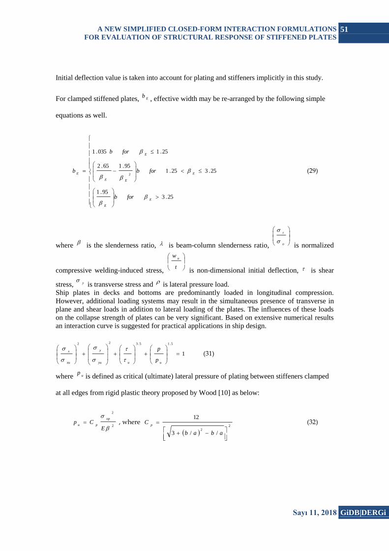
3. Finite Element Model for Inelastic Buckling Analyses
Authors investigated the structural ultimate capacity of the geometrical properties of the 60
three-bay panels having three and five equally spaced T-stiffeners under combine loads using
ANSYS Implicit non-linear finite element code [8]. All models were 3600 mm wide and it was
intended that they cover the full range of proportions of typical ship plates. A few models are
addressed in this paper. An elastic perfectly plastic material model without strain hardening may
be considered enough for pessimistic strength assessment of stiffened steel plates. Arc-length
method is applied to the solving of non-linear finite element stiffness equations. The material
yielding stress, o
, is 352.8 MPa, Young’s modulus, ,E 205800 MPa and the poisson ratio, ,
is assumed to be 0.30. Four-nodded shell elements are used to model stiffened plate, and a fine
mesh is conducted to adequately capture the stress and deformations. One of the examples of all
investigated models is shown in Figure 3.
Figure 3. ANSYS solid model for three-bay grillages in this study
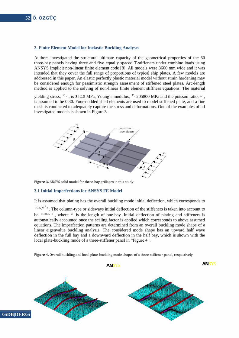
3.1 Initial Imperfections for ANSYS FE Model
It is assumed that plating has the overall buckling mode initial deflection, which corresponds to
t2
050 . . The column-type or sideways initial deflection of the stiffeners is taken into account to
be a00250 . , where a is the length of one-bay. Initial deflection of plating and stiffeners is
automatically accounted once the scaling factor is applied which corresponds to above assumed
equations. The imperfection patterns are determined from an overall buckling mode shape of a
linear eigenvalue buckling analysis. The considered mode shape has an upward half wave
deflection in the full bay and a downward deflection in the half bay, which is shown with the
local plate-buckling mode of a three-stiffener panel in “Figure 4”.
Figure 4. Overall buckling and local plate-buckling mode shapes of a three-stiffener panel, respectively

A NEW SIMPLIFIED CLOSED-FORM INTERACTION FORMULATIONS
FOR EVALUATION OF STRUCTURAL RESPONSE OF STIFFENED PLATES 53
Sayı 11, 2018 GiDB|DERGi
For residual stress distribution Faulkner’s model is used to represent the distribution of the
stresses, and is incorporated into ANSYS finite element model as a simple representation of the
actual residual stress present in the stiffened panels. The tensile regions around the stiffeners
represented as a tension block having base width proportional to the plate thickness ( x platet
)
where the value of typically ranges 3.5 and 4 in a ship structures. It is considered to be 3.5 in
this study.
3.2 Comparison between ANSYS FEM and Simplified Closed-form Formulations
From extensive FE non-linear numerical calculations, four cases are addressed in this paper.
Typical ship panel geometries studied are summarized in Table 2. Table 2. Geometric properties of stiffened panels analyzed in this paper
Specime
n no.
(Plate Slenderness
)
(Beam-column
slenderness)
(Aspect ratio)
Plate initial
deflection (mm)
(0.052t)
Stiffener initial
deflection (mm)
(0.0025a
)
Residual Stress
for stiffened plate (MPa)
op (MPa
)
ow (MPa
)
of (MPa
)
Case 1 1.77 0.83 2.00 3.30 4.50 35.3 352.8 352.8 352.8 Case 2 1.77 0.86 2.94 3.30 6.60 35.3 352.8 352.8 352.8 Case 3 1.55 0.72 4.40 1.93 6.60 35.3 352.8 352.8 352.8 Case 4 2.48 1.22 4.40 3.08 6.60 35.3 352.8 352.8 352.8
3.3 Computed FE Results
Figure 4 indicates Von Misses stress distributions obtained from ANSYS, while Figure 5 shows
stress-strain relationships with considering initial deflection effects from simple design
equations and ANSYS FEM as well.
Case 1
Case 2

54 Ö. ÖZGÜÇ
GiDB|DERGi Sayı 11, 2018
Case 3
Case 4
Figure 4. Von Misses stress distribution with ignoring residual stress for considered all cases, Case1, Case2, Case3 and Case 4, respectively
Case 1 Case 2
Case 3
Case 4
Figure 5. Comparison of ANSYS FEM with approximate formulation for Case1, Case2, Case3 and Case 4, respectively with initial deflection effect
0 .0 0
0 .2 0
0 .4 0
0 .6 0
0 .8 0
1 .0 0
0 .0 0 .5 1 .0 1 .5 2 .0
A x ia l D is p la c e me n t / Y ie ld D is p la c e me n t
Ax
ial
Str
es
s /
Yie
ld S
tre
ss
A NS Y S FEM
Pr e s e n t Me th o d
0 .0 0
0 .2 0
0 .4 0
0 .6 0
0 .8 0
1 .0 0
0 .0 0 .5 1 .0 1 .5
A x ia l D is p la c e me n t / Y ie ld D is p la c e me n t
Ax
ial
Str
es
s /
Yie
ld S
tre
ss
A NS Y S FEM
Pr e s e n t Me th o d
0 .0 0
0 .2 0
0 .4 0
0 .6 0
0 .8 0
1 .0 0
0 .0 0 .2 0 .4 0 .6 0 .8 1 .0 1 .2
A x ia l D is p la c e m e n t / Y ie ld D is p la c e m e n t
Ax
ial
Str
es
s /
Yie
ld S
tre
ss
A N S Y S FEM
Pr e s e n t M e th o d
0 .0 0
0 .2 0
0 .4 0
0 .6 0
0 .8 0
1 .0 0
0 .0 0 .5 1 .0 1 .5
A x ia l D is p la c e me n t / Y ie ld D is p la c e me n t
Ax
ial
Str
es
s /
Yie
ld S
tre
ss
A NS Y S FEM
Pr e s e n t Me th o d

A NEW SIMPLIFIED CLOSED-FORM INTERACTION FORMULATIONS
FOR EVALUATION OF STRUCTURAL RESPONSE OF STIFFENED PLATES 55
Sayı 11, 2018 GiDB|DERGi
As demonstrated, collapse behaviour of structural members composing a cross section of a hull
girder largely affects the collapse behaviour of the cross section and its ultimate strength as
whole. From this viewpoint, it is very important to know how accurately the applied method
simulates the collapse response and predicts the ultimate strength of individual structural
members as stiffened plates. Comparisons of ultimate strength capacities using ANSYS FEM
and simplified closed-form formulations are very consistent for all cases studied in this paper.
3.4 Interaction Capacity Curve
New proposed interaction formula is also validated results reported by DNV Research Team [6].
In this paper, capacity curves for combined loads calculated by ABAQUS, DNV PULS, DNV
and GL rules are presented with present method.
3.5 Biaxial Compression
Capacity curves for bi-axial compression of bottom panel of a 173 m tanker are presented in
Figure 6, while Table 3. summarizes main particulars of investigated model. Results for the
same panel under combined in-plane compression and lateral pressure are presented in Figure 7.
Table 3. The main particulars of the tanker bottom panel. Length of stiffened panel 2400 mm
Stiffener spacing 800 mm Plate thickness 13.5 mm
Web height 240 mm Web thickness 11 mm
Stiffeners 6 longitudinal Bulb profiles Yield stress 355 MPa
Young’s modulus 208000 MPa Poisson ratio 0.3
Figure 6. Tanker bottom panel, biaxial compression without lateral pressure
Figure 7. Tanker bottom panel, biaxial compression with lateral pressure, 151.0p MPa
The comparisons of ultimate strength capacities using ABAQUS, PULS and present method are
very consistent. Such deviations are to be expected since the applied methods are very different.
Typically, the largest deviations are for regions in load space where the failure mode is not
unique and obtained results depend strongly on how the geometrical imperfections are modelled
0
2 0
4 0
6 0
8 0
1 0 0
1 2 0
1 4 0
1 6 0
0 5 0 1 0 0 1 5 0 2 0 0 2 5 0 3 0 0
A B A Q U S -F E M
P re s e n t M e t h o d
D N V R u le s
G L R u le s
P U L S
0
2 0
4 0
6 0
8 0
1 0 0
1 2 0
1 4 0
0 5 0 1 0 0 1 5 0 2 0 0 2 5 0 3 0 0
A B A Q US - FEM
Pr e s e n t Me th o d
PUL S

56 Ö. ÖZGÜÇ
GiDB|DERGi Sayı 11, 2018
especially with respect to shape and definition of boundary condition. It is seen that reduction in
the in-plane capacity is not very much reduced when the design lateral pressure is employed.
The reduction is somewhat lesser for present method than ABAQUS and PULS.
It is seen that present approach predicts more capacity than both of the rule formulations in the
bi-axial region. For pure axial compression, DNV Rules seem to be overly conservative when
compared with all prediction methods, while for pure transverse compression GL Rules seem to
be non-conservative. The present method curve is more convex, which is also the case for
ABAQUS, PULS and DNV Rules, while the GL Rules interaction curve is close to linear.
3.6 Effect of Shear Load
Capacity curves for combined shear load and transverse compression of a bulk carrier side panel
are presented in Figure 8, while Table 4. summarizes main particulars of investigated model.
The loading is typically compression perpendicular to the stiffener transverse direction acting
simultaneously with in-plane shear and lateral pressure from the sea. Results for the same panel
under combined transverse compression, shear and lateral pressure are presented in Figure 9.
Table 4. The main particulars of the Bulk Carrier side panel.
Length of stiffened panel 8800 mm Stiffener spacing 890 mm Plate thickness 14.5 mm
Web height 700 mm Web thickness 13 mm
Stiffeners 5 longitudinal Tee profiles Flange breadth 150 mm
Flange thickness 18 mm Yield stress 355 MPa
Young’s modulus 208000 MPa Poisson ratio 0.3
Figure 8. Bulk Carrier side panel, transverse compression and shear loading without lateral pressure
Figure 9. Bulk Carrier side panel, transverse compression, shear with lateral pressure, p=0.157 MPa
It can be seen that present method shows very reasonable results as compared to ABAQUS and
PULS analyses covering load combinations covering load combinations dominated by shear
0
5 0
1 0 0
1 5 0
2 0 0
2 5 0
0 2 0 4 0 6 0 8 0 1 0 0
A B A Q US - FEM
Pr e s e n t Me th o d
PUL S
DNV Ru le s
G L Ru le s
0
5 0
1 0 0
1 5 0
2 0 0
2 5 0
0 2 0 4 0 6 0 8 0
A B A Q US - FEM
Pr e s e n t Me th o d
PUL S

A NEW SIMPLIFIED CLOSED-FORM INTERACTION FORMULATIONS
FOR EVALUATION OF STRUCTURAL RESPONSE OF STIFFENED PLATES 57
Sayı 11, 2018 GiDB|DERGi
loading as well as load combinations dominated by transverse compression. The presence of
lateral pressure is not very significant for the in-plane capacity of this pane, though more so for
transverse dominated loading than for pure shear. It is seen that both the rule formulations
overpredict the capacity for pure transverse compression, while they significantly underestimate
the capacity in the combined load region of the capacity curve.
3.7 Effect of Lateral Pressure
Capacity curves for the axial capacity for a tanker bottom panel are presented as a function of
lateral pressure in Figure 10, while Table 5. summarizes main particulars of investigated model.
The transverse capacity for the same panel is presented as a function of lateral pressure in
Figure 11.
Table 5. The main particulars of the tanker bottom panel. Length of each bay (mm) 5120
Panel breadth (mm) 9100
Plate thickness (mm) 20
Web height (mm) 598.5
Web thickness (mm) 12
Stiffeners 9 longitudinal T-stiffeners
Flange breadth (mm) 200
Flange thickness (mm) 20
Yield stress (MPa) 315
Young’s modulus (MPa) 208000
Poisson ratio 0.30
Figure 10. Effect of lateral pressure on axial capacity for tanker bottom panel
Figure 11. Effect of lateral pressure on transverse capacity for tanker bottom panel
It is seen that present method in the axial capacity predicts reasonable results as compared to
ABAQUS, while the rule formulations overpredict the capacity of the panel since they are not
affected by influence of lateral pressure.
0
5 0
1 0 0
1 5 0
2 0 0
2 5 0
3 0 0
0 0 .1 0 .2 0 .3 0 .4 0 .5 0 .6
A NS Y S FEM
Pr e s e n t s tu d y
PUL S
DNV Ru le s
G L Ru le s

58 Ö. ÖZGÜÇ
GiDB|DERGi Sayı 11, 2018
It is seen that present method in the transverse capacity estimate slightly more results up to 0.20
MPa since transverse capacity overpredicts when lateral pressure is zero, however, it estimates
very good at 0.30 MPa, where it underestimates at fixed pressure of 0.55 MPa. Rule
formulations overpredict transverse capacity even for zero lateral pressure and more so for
increasing magnitude of pressure. The results indicate that lateral pressure has important
influence on the buckling capacity and should be taken into account.
4. Discussion and Conclusion
Simplified closed-form interaction formulations for the ultimate capacity assessment of
stiffened panels has been developed based on a large number of non-linear finite element
analyses using the commercial program ANSYS. It is believed that full nonlinear finite element
codes are able to predict buckling deflection an accuracy which is sufficient for advanced design
purposes, on condition that the analyses are done properly such as boundary conditions, mesh
size, model extent, element types and imperfections. Validation of the proposed model is
conducted by use of non-linear finite element calculations and by existing ship rules used by
DNV and GL Rules. It is found that present model is generally consistent with results obtained
from by ABAQUS and PULS. The rules used by Classification Societies are found to be
conservative for some case and non-conservative for other cases as compared with ABAQUS
and PULS. Therefore, it is difficult to assess the actual safety margin using these formulations.
The main advantage of the approximate method relative to FEM results from the time
consumption both in the creation of model and in the CPU time, so it can be used for practical
applications in ship design.
References
[1] Bonello, M.A.; Chryssanthopouls, M.K.; Dowling, P.J. Ultimate Strength Design of
Stiffened Plates under Axial Compression and Bending, Marine Structure, 1993, Vol. 6, pp.
532-552.
[2] Faulkner, D. A review of Effective Plating for use in the Analysis of Stiffened Plating in
Bending and Compression, Journal of Ship Research, 1975, Vol. 19, No. 1, pp. 1-17.
[3] Grondin, G.Y.; Chen, Q.; Elwi A.E.; Cheng J.J.R. Buckling of Stiffened Steel Plates-
Validation of a Numerical Model, Journal of Constructional Steel Research, 1998, Vol. 45, No.
2, pp. 125-148.
[4] Grondin, G.Y.; Chen, Q.; Elwi, A.E.; Cheng J.J.R. Buckling of Stiffened Steel Plates- A
Parametric Study, Journal of Constructional Steel Research, 1999, Vol. 50, No. 2, pp. 151-175.
[5] Hu, S.Z.; Chen, Q.; Pegg, N.; Zimmercman, T.J.E. Ultimate Collapse tests of Stiffened Plate
Ship Structural Units, Marine Structure, 1997, Vol. 10, pp. 587-610.
[6] Hughes, O.F.; Ghosh, B.; Chen, Y. Improved Prediction of Simultaneous Local and Overall
Buckling of Stiffened Panels, Thin-Walled Structures, Vol. 42, pp. 827-856, 2004. [7] Murray
N.W., Buckling of Stiffened Panel Loaded Axially and in Bending. Structure Engineer, 1973,
Vol. 51, No. 8, pp. 285-301.
[7] Steen, E.; Byklum, E.; Vilming, K.; Ostvolds, K. Computerized Buckling Models for
Ultimate Strength Assessment of Stiffened Ship Hull Panels, 9th Symposium on Practical
Design of Ships and Other Floating Structures, 2004, Luebeck-Travemuende, Germany.
[8] Wood, R.H. Plastic and Inelastic Design of Slabs and Plates, The Ronald Press, 1961, New
York.
[9] Chaithanya, P.P.; Das, P.K.; Crow, A.; Hunt, S. The effect of distortion on the buckling
strength of stiffened panels. Ships and Offshore Structures, 2010, Vol.5.

A NEW SIMPLIFIED CLOSED-FORM INTERACTION FORMULATIONS
FOR EVALUATION OF STRUCTURAL RESPONSE OF STIFFENED PLATES 59
Sayı 11, 2018 GiDB|DERGi
[10] Xu, M.C.; Soares, C.G. Numerical assessment of experiments on the ultimate strength of
stiffened panels, Engineering Structures, 2012, Vol.45, pp. 460–471.
[11] Ozguc, O.; Das, P.K.; Barltrop, N. The new simple design equations for the ultimate
compressive strength of imperfect stiffened plates. Ocean Engineering, 2007, Vol. 34, Issue 7,
pp. 970–986.
[12] Paik, J.K.; Kim, B.J.; Seo, J.K. Methods for ultimate limit state assessment of ships and
ship-shaped offshore structures: Part II stiffened panels. Ocean Engineering, 2008, Volume 35,
Issue 2, pp. 271–280.
[13] Tekgoz, M.; Garbatov, Y.; Soares, C.G. Ultimate strength assessment for the effect of finite
element modelling. Maritime Engineering and Technology, 2012.
[14] Cho, S.R.; Kim, H.S.; Doh, H.M.; Chon, Y.K. Ultimate strength formulation for stiffened
plates subjected to combined axial compression, transverse compression, shear force and lateral
pressure loadings. Ships and Offshore Structures, 2013, Vol.8.
[15] Zhang, S. A. review and study on ultimate strength of steel plates and stiffened panels in
axial compression. Ships and Offshore Structures, 2016, Vol.11.


