

ABS (DIAGNOSTICS)
ABS
Page1. Basic Diagnostic Procedure ........................................................................22. Check List for Interview...............................................................................63. General Description ..................................................................................104. Electrical Components Location................................................................125. Control Module I/O Signal .........................................................................146. Subaru Select Monitor...............................................................................187. Read Diagnostic Trouble Code (DTC) ......................................................218. Inspection Mode........................................................................................229. Clear Memory Mode..................................................................................23
10. ABS Warning Light Illumination Pattern ....................................................2411. List of Diagnostics Trouble Code (DTC) ...................................................2512. Diagnostics Chart with Diagnosis Connector ............................................2913. Diagnostics Chart with Subaru Select Monitor..........................................9514. General Diagnostics Table......................................................................175

ABS (DIAGNOSTICS)BASIC DIAGNOSTIC PROCEDURE
1. Basic Diagnostic ProcedureA: PROCEDURE1. WITHOUT SUBARU SELECT MONITOR
CAUTION:Remove foreign matter (dust, water, etc.) from the ABSCM&H/U connector during removal and instal-lation.
NOTE:• To check the harness for broken wires or short circuits, shake it while holding it or the connector.• When the ABS warning light illuminates, read and record the diagnostic trouble code (DTC) indicated byABS warning light.
Step Value Yes No1 CHECK PRE-INSPECTION.
1)Ask the customer when and how trouble occurred using interview checklist. <Ref. to ABS-6, Check List for Interview.>2)Before performing diagnosis, inspect the unit which might influence ABS problem. <Ref. to ABS-10, INSPECTION, General Description.>Is the unit that might influence the ABS prob-lem normal?
Unit is normal. Go to step 2. Repair or replace each unit.
2 CHECK INDICATION OF DIAGNOSTIC TROUBLE CODE (DTC).Calling up the DTC. <Ref. to ABS-21, Read Diagnostic Trouble Code (DTC).>Is the ABS warning light normal?
ABS warning light is normal. Go to step 3. Inspect using diag-nostic chart for ABS warning light failure.<Ref. to ABS-29, Diagnos-tics Chart with Diagnosis Con-nector.>
NOTE:Call up DTC againafter inspectingABS warning light.<Ref. to ABS-21,Read DiagnosticTrouble Code(DTC).>
3 CHECK DIAGNOSTIC TROUBLE CODE (DTC). Record all DTCs. Is only the start code issued?
Only the start code is issued. Go to step 4. Go to step 5.
4 PERFORM THE GENERAL DIAGNOSTICS. 1)Inspect using “General Diagnostics Table”. <Ref. to ABS-175, General Diagnostics Table.>2)Perform the clear memory mode. <Ref. to ABS-23, WITHOUT SUBARU SELECT MONI-TOR, OPERATION, Clear Memory Mode.>3)Perform the inspection mode. <Ref. to ABS-22, Inspection Mode.>Calling up the DTC. <Ref. to ABS-21, Read Diagnostic Trouble Code (DTC).>Is only the start code issued?
Only the start code is issued. Complete the diagnosis.
Go to step 5.
ABS-2

ABS (DIAGNOSTICS)BASIC DIAGNOSTIC PROCEDURE
5 PERFORM THE DIAGNOSIS.1)Repair trouble cause.
NOTE:For DTC list, refer to “List of Diagnostics Trou-ble Code (DTC)”.<Ref. to ABS-25, WITHOUTSUBARU SELECT MONITOR, LIST, List of Di-agnostics Trouble Code (DTC).>
2)Perform the clear memory mode. <Ref. to ABS-23, WITHOUT SUBARU SELECT MONI-TOR, OPERATION, Clear Memory Mode.>3)Perform the inspection mode. <Ref. to ABS-22, Inspection Mode.>4)Calling up the DTC. <Ref. to ABS-21, Read Diagnostic Trouble Code (DTC).>Is only the start code issued?
Only the start code is issued. Complete the diagnosis.
Repeat the step5 until only start code is issued.
Step Value Yes No
ABS-3

ABS (DIAGNOSTICS)BASIC DIAGNOSTIC PROCEDURE
2. WITH SUBARU SELECT MONITOR
CAUTION:Remove foreign matter (dust, water, etc.) from the ABSCM&H/U connector during removal and instal-lation.
NOTE:• To check the harness for broken wires or short circuits, shake it while holding it or the connector.• Check list for interview. <Ref. to ABS-6, Check List for Interview.>
Step Value Yes No1 CHECK PRE-INSPECTION.
1)Ask the customer when and how trouble occurred using interview checklist. <Ref. to ABS-6, Check List for Interview.>2)Before performing diagnosis, inspect the unit which might influence the ABS problem. <Ref. to ABS-10, INSPECTION, General Descrip-tion.>Is the unit that might influence the ABS prob-lem normal?
Unit is normal. Go to step 2. Repair or replace each unit.
2 CHECK INDICATION OF DIAGNOSTIC TROUBLE CODE (DTC) DISPLAY. 1)Turn the ignition switch to OFF.2)Connect the SUBARU SELECT MONITOR to data link connector.3)Turn the ignition switch to ON and SUBARU SELECT MONITOR to ON.
NOTE:If the communication function of select monitorcannot be executed normally, check communi-cation circuit. <Ref. to ABS-95, COMMUNICA-TION FOR INITIALIZING IMPOSSIBLE,Diagnostics Chart with Subaru Select Monitor.>4)Read the DTC. <Ref. to ABS-19, READ CURRENT DATA, OPERATION, Subaru Select Monitor.>5)Record all DTCs and frame data.Is DTC displayed?
DTC is not displayed. Go to step 3. Go to step 4.
3 PERFORM THE GENERAL DIAGNOSTICS. 1)Inspect using “General Diagnostics Table”. <Ref. to ABS-175, General Diagnostics Table.>2)Perform the clear memory mode. <Ref. to ABS-19, CLEAR MEMORY MODE, OPERA-TION, Subaru Select Monitor.>3)Perform the inspection mode. <Ref. to ABS-22, Inspection Mode.>4)Calling up the DTC. <Ref. to ABS-18, READ DIAGNOSTIC TROUBLE CODE (DTC), OPERATION, Subaru Select Monitor.>Check DTC is not displayed.Is the ABS warning light turned off?
ABS warning light is turned off. Complete the diagnosis.
Go to step 4.
ABS-4
ABS (DIAGNOSTICS)BASIC DIAGNOSTIC PROCEDURE
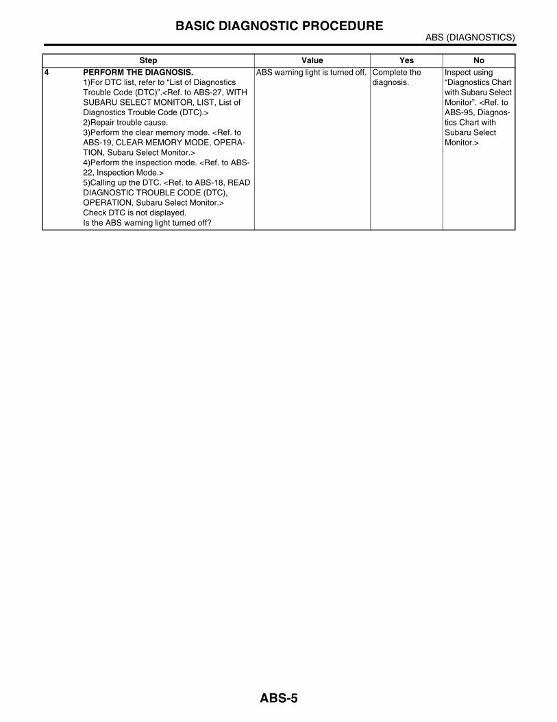
4 PERFORM THE DIAGNOSIS.1)For DTC list, refer to “List of Diagnostics Trouble Code (DTC)”.<Ref. to ABS-27, WITH SUBARU SELECT MONITOR, LIST, List of Diagnostics Trouble Code (DTC).>2)Repair trouble cause.3)Perform the clear memory mode. <Ref. to ABS-19, CLEAR MEMORY MODE, OPERA-TION, Subaru Select Monitor.>4)Perform the inspection mode. <Ref. to ABS-22, Inspection Mode.>5)Calling up the DTC. <Ref. to ABS-18, READ DIAGNOSTIC TROUBLE CODE (DTC), OPERATION, Subaru Select Monitor.>Check DTC is not displayed.Is the ABS warning light turned off?
ABS warning light is turned off. Complete the diagnosis.
Inspect using “Diagnostics Chart with Subaru Select Monitor”. <Ref. to ABS-95, Diagnos-tics Chart with Subaru Select Monitor.>
Step Value Yes No
ABS-5
ABS (DIAGNOSTICS)CHECK LIST FOR INTERVIEW
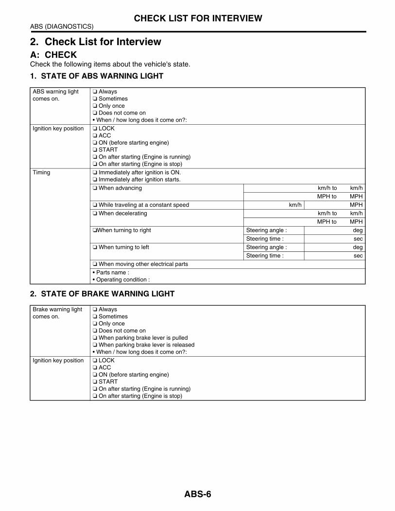
2. Check List for InterviewA: CHECKCheck the following items about the vehicle's state.
1. STATE OF ABS WARNING LIGHT
2. STATE OF BRAKE WARNING LIGHT
ABS warning light comes on.
Always Sometimes Only once Does not come on• When / how long does it come on?:
Ignition key position LOCK ACC ON (before starting engine) START On after starting (Engine is running) On after starting (Engine is stop)
Timing Immediately after ignition is ON. Immediately after ignition starts.
When advancing km/h to km/h
MPH to MPH
While traveling at a constant speed km/h MPH
When decelerating km/h to km/h
MPH to MPH
When turning to right Steering angle : deg
Steering time : sec
When turning to left Steering angle : deg
Steering time : sec
When moving other electrical parts
• Parts name :• Operating condition :
Brake warning light comes on.
Always Sometimes Only once Does not come on When parking brake lever is pulled When parking brake lever is released• When / how long does it come on?:
Ignition key position LOCK ACC ON (before starting engine) START On after starting (Engine is running) On after starting (Engine is stop)
ABS-6

ABS (DIAGNOSTICS)CHECK LIST FOR INTERVIEW
3. SYMPTOMS
Timing Immediately after ignition is ON. Immediately after ignition starts.
When advancing km/h to km/h
MPH to MPH
While traveling at a constant speed km/h MPH
When decelerating km/h to km/h
MPH to MPH
When turning to right Steering angle : deg
Steering time : sec
When turning to left Steering angle : deg
Steering time : sec
When moving other electrical parts
• Parts name :• Operating condition :
ABS operating condi-tion
Performs no work.
Operates only when abruptly applying brakes. Vehicle speed : km/h
MPH
• How to step on brake pedal :
a) Operating time : sec
b) Operating noise : Produce / Does not produce
• What kind of noise? Knock Gong gong Bong Buzz Gong gong buzz Others :
c) Reaction force of brake pedal
Stick Press down once with a clunk Press and released Others :
ABS-7

ABS (DIAGNOSTICS)CHECK LIST FOR INTERVIEW
Behavior of vehicle a) Directional stability cannot be obtained or steering refuses to work when applying brakes : Yes / No
• When : Vehicle turns to right Vehicle turns to left Spins Others :
b) Directional stability cannot be obtained or steering refuses to work when accelerating : Yes / No
• When : Vehicle turns to right Vehicle turns to left Spins Others :
c) Brakes out of order : Yes / No
• What : Braking distance is long Brakes lock or drag Pedal stroke is long Pedal sticks Others :
d) Poor acceleration : Yes / No
• What : Fails to accelerate Engine stalls Others :
e) Occurrence of vibration : Yes / No
• Where• What kind :
f) Occurrence of abnormal noise : Yes / No
• Where• What kind :
g) Occurrence of other phenomena : Yes / No
• What kind :
ABS-8

ABS (DIAGNOSTICS)CHECK LIST FOR INTERVIEW
4. CONDITIONS UNDER WHICH TROUBLE OCCURS
Environment a) Weather Fine Cloudy Rainy Snowy Various/Others :
b) Ambient temperature °F (°C)
c) Road Urban area Suburbs Highway General road Ascending slope Descending slope Paved road Gravel road Muddy road Sandy place Others :
d) Road surface Dry Wet New-fallen snow Compressed snow Frozen slope Others :
Condition a) Brakes Deceleration : g
Continuous / Intermittent
b) Accelerator Acceleration : g
Continuous / Intermittent
c) Vehicle speed km/h MPH
Advancing Accelerating Reducing speed Low speed Turning Others :
d) Tire inflation pressure Front RH tire : kPa
Front LH tire : kPa
Rear RH tire : kPa
Rear LH tire : kPa
e) Degree of wear Front RH tire :
Front LH tire :
Rear RH tire :
Rear LH tire :
f) Genuine parts are used. : Yes / No
g) Chain is passed around tires. : Yes / No
h) T tire is used. : Yes / No
i) Condition of suspension alignment :
j) Loading state :
k) Repair parts are used. : Yes / No
• What :
l) Others :
ABS-9
ABS (DIAGNOSTICS)GENERAL DESCRIPTION
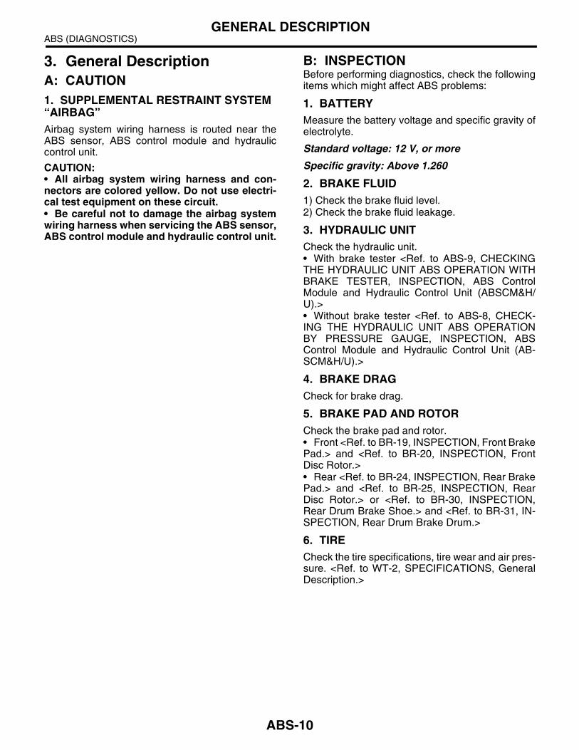
3. General DescriptionA: CAUTION1. SUPPLEMENTAL RESTRAINT SYSTEM “AIRBAG”Airbag system wiring harness is routed near theABS sensor, ABS control module and hydrauliccontrol unit.
CAUTION:• All airbag system wiring harness and con-nectors are colored yellow. Do not use electri-cal test equipment on these circuit.• Be careful not to damage the airbag systemwiring harness when servicing the ABS sensor,ABS control module and hydraulic control unit.
B: INSPECTIONBefore performing diagnostics, check the followingitems which might affect ABS problems:
1. BATTERYMeasure the battery voltage and specific gravity ofelectrolyte.
Standard voltage: 12 V, or more
Specific gravity: Above 1.260
2. BRAKE FLUID1) Check the brake fluid level.2) Check the brake fluid leakage.
3. HYDRAULIC UNITCheck the hydraulic unit.• With brake tester <Ref. to ABS-9, CHECKINGTHE HYDRAULIC UNIT ABS OPERATION WITHBRAKE TESTER, INSPECTION, ABS ControlModule and Hydraulic Control Unit (ABSCM&H/U).>• Without brake tester <Ref. to ABS-8, CHECK-ING THE HYDRAULIC UNIT ABS OPERATIONBY PRESSURE GAUGE, INSPECTION, ABSControl Module and Hydraulic Control Unit (AB-SCM&H/U).>
4. BRAKE DRAGCheck for brake drag.
5. BRAKE PAD AND ROTORCheck the brake pad and rotor.• Front <Ref. to BR-19, INSPECTION, Front BrakePad.> and <Ref. to BR-20, INSPECTION, FrontDisc Rotor.>• Rear <Ref. to BR-24, INSPECTION, Rear BrakePad.> and <Ref. to BR-25, INSPECTION, RearDisc Rotor.> or <Ref. to BR-30, INSPECTION,Rear Drum Brake Shoe.> and <Ref. to BR-31, IN-SPECTION, Rear Drum Brake Drum.>
6. TIRECheck the tire specifications, tire wear and air pres-sure. <Ref. to WT-2, SPECIFICATIONS, GeneralDescription.>
ABS-10

ABS (DIAGNOSTICS)GENERAL DESCRIPTION
C: PREPARATION TOOL1. SPECIAL TOOLS
2. GENERAL PURPOSE TOOLS
ILLUSTRATION TOOL NUMBER DESCRIPTION REMARKS
24082AA210 CARTRIDGE Troubleshooting for electrical systems.
22771AA030 SUBARU SELECT MONITOR KIT
Troubleshooting for electrical systems.
TOOL NAME REMARKS
Circuit tester Used for measuring resistance, voltage and ampere.
Oscilloscope Used for measuring sensor.
ST24082AA210
ST22771AA030
ABS-11
ABS (DIAGNOSTICS)ELECTRICAL COMPONENTS LOCATION
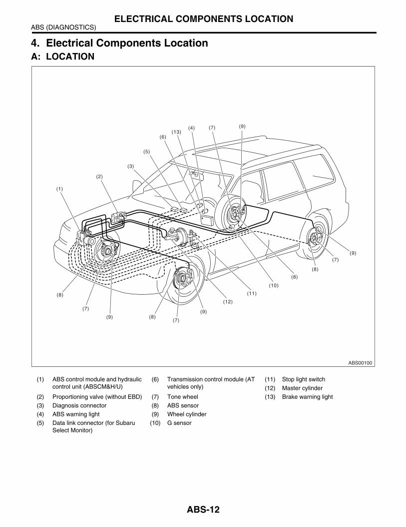
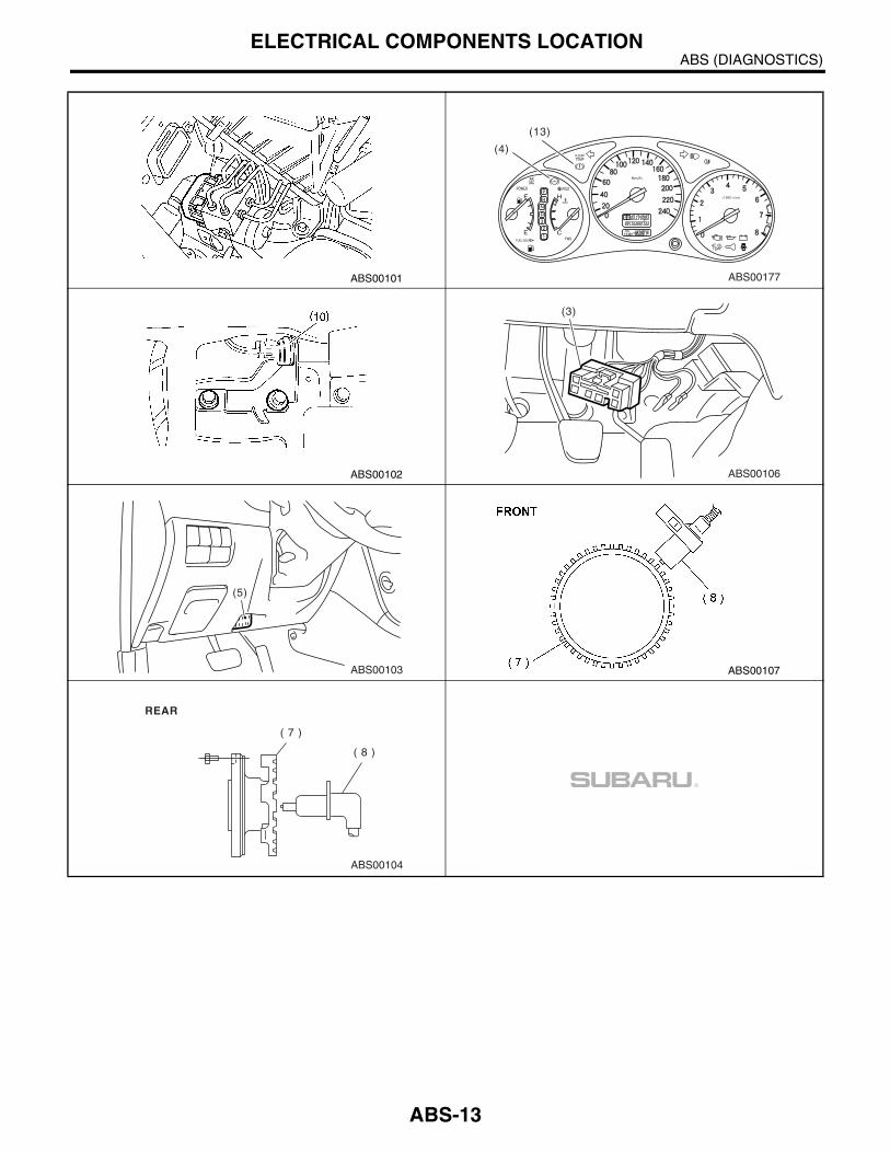
4. Electrical Components LocationA: LOCATION
(1) ABS control module and hydraulic control unit (ABSCM&H/U)
(6) Transmission control module (AT vehicles only)
(11) Stop light switch
(12) Master cylinder
(2) Proportioning valve (without EBD) (7) Tone wheel (13) Brake warning light
(3) Diagnosis connector (8) ABS sensor
(4) ABS warning light (9) Wheel cylinder
(5) Data link connector (for Subaru Select Monitor)
(10) G sensor
ABS00100
(9)(9)
(9)
(1)
(2)
(3)
(5)
(6)
(4) (7) (9)(13)
(10)
(11)
(12)(8)
(8)
(8)
(8)
(7)
(7)
(7)
ABS-12
ABS (DIAGNOSTICS)ELECTRICAL COMPONENTS LOCATION
ABS00101
(4)
(13)
ABS00177
ABS00102 ABS00106
(3)
ABS00103
(5)
ABS00107
ABS00104
( 7 )
( 8 )
REAR
ABS-13

ABS (DIAGNOSTICS)CONTROL MODULE I/O SIGNAL
5. Control Module I/O SignalA: ELECTRICAL SPECIFICATION
NOTE:• The terminal numbers in ABS control module and hydraulic control unit connector are as shown in the fig-ure.• When the connector is removed from ABSCM&H/U, the connector switch closes the circuit between ter-minal No. 22 and No. 23. The ABS warning light illuminates.
(1) ABS control module and hydraulic control unit connector
(2) Connector switch
ABS00182
1 2 3 4 5 6 7 8 9 10 11 12 13 14 1516 17 18 19 20 21 22
27 28 29 30 3123 24 25 26
F49B301 or
(2)
(1)
ABS-14

ABS (DIAGNOSTICS)CONTROL MODULE I/O SIGNAL
*1: Measure the I/O signal voltage after removing the connector from the ABSCM&H/U terminal.*2: Measure the I/O signal voltage at connector (B98), (B37) ,(B38), (F48) or (F103).
ContentsTerminal No.
(+) — (−)Input/Output signal
Measured value and measuring conditions
ABS sensor*2(Wheel speed sensor)
Front left wheel 9 — 10
0.12 — 1 V(When it is 20 Hz.)
Front right wheel 11 — 12
Rear left wheel 7 — 8
Rear right wheel 14 — 15
Valve relay power supply*1 24 — 23 10 — 15 V
Motor relay power supply*1 25 — 23 10 — 15 V
G sensor*2
Power supply 30 — 28 4.75 — 5.25 V
Ground 28 —
Output 6 — 28 2.1 — 2.5 V when vehicle is in horizontal position.
Stop light switch*1 2 — 23Less than 1.5 V when the stop light is OFF and, 10 — 15 V
when the stop light is ON.
ABS warning light*2 22 — 23Less than 1.5 V within 1.5 seconds immediately after ignition switch has been turned to ON, and 10 — 15 V after 1.5 sec-
onds has elapsed.
Brake warning light*2(EBD warning light)
21 — 23Less than 1.5 V within 1.5 seconds immediately after ignition switch has been turned to ON, and 10 — 15 V after 1.5 sec-
onds has elapsed.
AT ABS signal(AT vehicles only)
31 — 23Less than 1.5 V when the ABS control still operates and more
than 5.5 V when ABS does not operate.
ABS operation signal monitor 3 — 23Less than 1.5 V when the ABS control still operates and more
than 5.5 V when ABS does not operate.
Select monitor*2Data is received. 20 — 23 Less than 1.5 V when no data is received.
Data is sent. 5 — 23 4.75 — 5.25 V when no data is sent.
ABS diagnosis connec-tor
Terminal No. 3 29 — 23 10 — 15 V when ignition switch is ON.
Terminal No. 6 4 — 23 10 — 15 V when ignition switch is ON.
Power supply*1 1 — 23 10 — 15 V when ignition switch is ON.
Grounding line 23 —
Grounding line 26 —
ABS-15
ABS (DIAGNOSTICS)CONTROL MODULE I/O SIGNAL
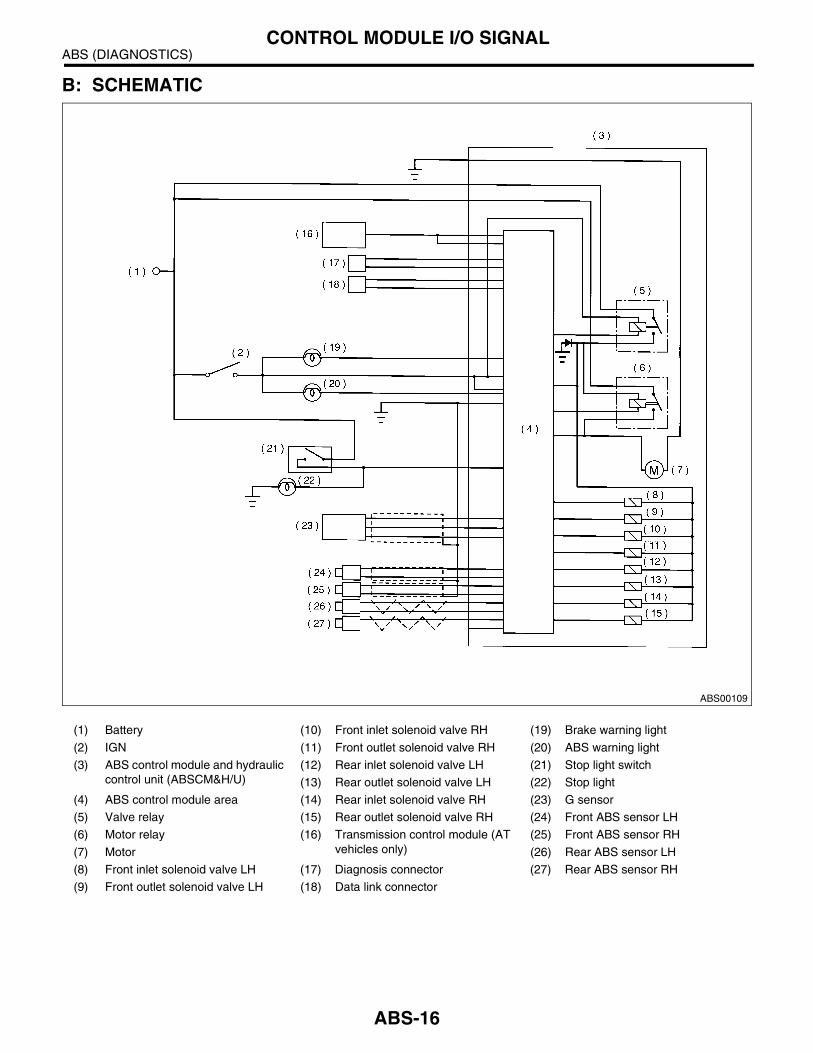
B: SCHEMATIC
(1) Battery (10) Front inlet solenoid valve RH (19) Brake warning light
(2) IGN (11) Front outlet solenoid valve RH (20) ABS warning light
(3) ABS control module and hydraulic control unit (ABSCM&H/U)
(12) Rear inlet solenoid valve LH (21) Stop light switch
(13) Rear outlet solenoid valve LH (22) Stop light
(4) ABS control module area (14) Rear inlet solenoid valve RH (23) G sensor
(5) Valve relay (15) Rear outlet solenoid valve RH (24) Front ABS sensor LH
(6) Motor relay (16) Transmission control module (AT vehicles only)
(25) Front ABS sensor RH
(7) Motor (26) Rear ABS sensor LH
(8) Front inlet solenoid valve LH (17) Diagnosis connector (27) Rear ABS sensor RH
(9) Front outlet solenoid valve LH (18) Data link connector
ABS00109
ABS-16

ABS (DIAGNOSTICS)CONTROL MODULE I/O SIGNAL
C: WAVEFORM
ABS00110
ABS-17
ABS (DIAGNOSTICS)SUBARU SELECT MONITOR
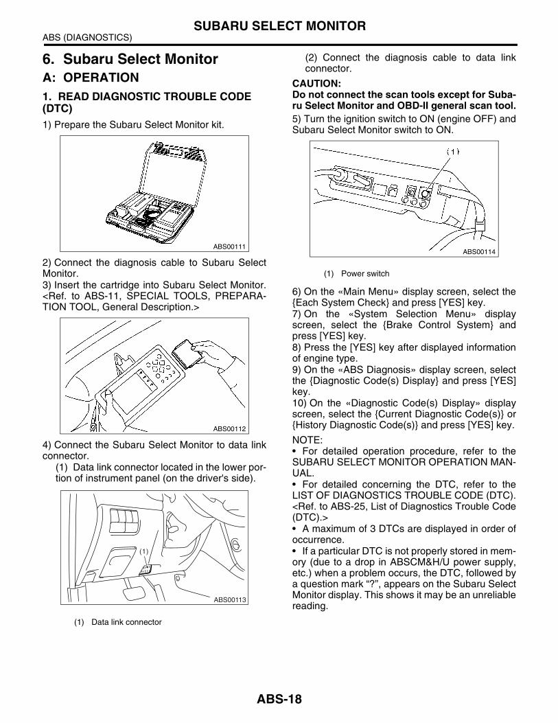
6. Subaru Select MonitorA: OPERATION1. READ DIAGNOSTIC TROUBLE CODE (DTC)1) Prepare the Subaru Select Monitor kit.
2) Connect the diagnosis cable to Subaru SelectMonitor.3) Insert the cartridge into Subaru Select Monitor.<Ref. to ABS-11, SPECIAL TOOLS, PREPARA-TION TOOL, General Description.>
4) Connect the Subaru Select Monitor to data linkconnector.
(1) Data link connector located in the lower por-tion of instrument panel (on the driver's side).
(2) Connect the diagnosis cable to data linkconnector.
CAUTION:Do not connect the scan tools except for Suba-ru Select Monitor and OBD-II general scan tool.5) Turn the ignition switch to ON (engine OFF) andSubaru Select Monitor switch to ON.
6) On the «Main Menu» display screen, select theEach System Check and press [YES] key.7) On the «System Selection Menu» displayscreen, select the Brake Control System andpress [YES] key.8) Press the [YES] key after displayed informationof engine type.9) On the «ABS Diagnosis» display screen, selectthe Diagnostic Code(s) Display and press [YES]key.10) On the «Diagnostic Code(s) Display» displayscreen, select the Current Diagnostic Code(s) orHistory Diagnostic Code(s) and press [YES] key.
NOTE:• For detailed operation procedure, refer to theSUBARU SELECT MONITOR OPERATION MAN-UAL.• For detailed concerning the DTC, refer to theLIST OF DIAGNOSTICS TROUBLE CODE (DTC).<Ref. to ABS-25, List of Diagnostics Trouble Code(DTC).>• A maximum of 3 DTCs are displayed in order ofoccurrence.• If a particular DTC is not properly stored in mem-ory (due to a drop in ABSCM&H/U power supply,etc.) when a problem occurs, the DTC, followed bya question mark “?”, appears on the Subaru SelectMonitor display. This shows it may be an unreliablereading.
(1) Data link connector
ABS00111
ABS00112
ABS00113
(1)
(1) Power switch
ABS00114
ABS-18

ABS (DIAGNOSTICS)SUBARU SELECT MONITOR
2. READ CURRENT DATA1) On the «Main Menu» display screen, select the Each System Check and press «YES» key.2) On the «System Selection Menu» display screen, select the Brake Control System and press «YES»key.3) Press the «YES» key after displayed the information of ABS type.4) On the «Brake Control Diagnosis» display screen, select the Current Data Display & Save and press«YES» key.5) On the «Data Display Menu» display screen, select the Data Display and press «YES» key.6) Using the scroll key, move the display screen up or down until desired data is shown.• A list of the support data is shown in the following table.
NOTE:For detailed operation procedure, refer to the SUBARU SELECT MONITOR OPERATION MANUAL.
3. CLEAR MEMORY MODE1) On the «Main Menu» display screen, select the2. Each System Check and press «YES» key.2) On the «System Select Menu» display screen,select the Brake System and press «YES» key.3) Press the «YES» key after displayed the infor-mation of engine type.4) On the «Brake Control Diagnosis» displayscreen, select the Clear Memory and press«YES» key.
5) When the “Done” and “turn ignition switch toOFF” are shown on display screen, turn the SubaruSelect Monitor and ignition switch to OFF.
NOTE:For detailed operation procedure, refer to the SUB-ARU SELECT MONITOR OPERATION MANUAL.
4. ABS SEQUENCE CONTROL
Display screen Contents to be monitored
LatestThe most recent DTC appears on select monitor display.
OldThe second most recent DTC appears on select monitor display.
OlderThe third most recent DTC appears on select monitor display.
ReferenceDTC issued after elapse of a specified period of time.
Display screen Contents to be monitored Unit of measure
FR Wheel Speed Wheel speed detected by Front ABS sensor RH is displayed km/h or MPH
FL Wheel Speed Wheel speed detected by Front ABS sensor LH is displayed km/h or MPH
RR Wheel Speed Wheel speed detected by Rear ABS sensor RH is displayed km/h or MPH
RL Wheel Speed Wheel speed detected by Rear ABS sensor LH is displayed km/h or MPH
Stop Light Switch Stop light switch signal ON or OFF
Stop Light Switch Stop light switch monitor voltage is displayed. V
G sensor output SignalVoltage equivalent to vehicle acceleration detected by analog G sensor is displayed.
V
Valve Relay Signal Valve Relay Signal ON or OFF
Motor Relay Signal Motor Relay Signal ON or OFF
ABS Signal to TCM ABS operation signal from ABS control module to TCM ON or OFF
ABS Warning Lamp ON operation of ABS warning light is displayed. ON or OFF
EBD warning light ON operation of EBD warning light is displayed. ON or OFF
Motor Relay Monitor Operating condition of motor relay is displayed. ON or OFF
Valve Relay Monitor Operating condition of the valve relay is displayed. ON or OFF
CCM Signal ABS operation signal from ABS control module to TCM ON or OFF
Display screen Contents to be monitored
Clear memory?Function of clearing DTC and freeze frame data.
Display screen
Contents to be monitored Index No.
ABS sequence control
Perform ABS sequence control by operating valve and pump motor sequen-tially.
<Ref. to ABS-11, ABS Sequence Con-trol.>
ABS-19

ABS (DIAGNOSTICS)SUBARU SELECT MONITOR
5. FREEZE FRAME DATA
NOTE:• Data stored at the time of trouble occurrence isshown on display.• Each time trouble occurs, the latest informationis stored in the freeze frame data in memory.• Freeze frame data will be memorized maximumto three.• If freeze frame data is not properly stored inmemory (due to a drop in ABSCM power supply,etc.), a DTC, preceded by a question mark “?”, ap-pears on the select monitor display. This shows itmay be an unreliable reading.
6. ANALOG DATA ARE DISPLAYED
7. ON/OFF DATA ARE DISPLAYED
Display screen Contents to be monitored
FR wheel speedWheel speed detected by Front ABS sensor RH is displayed in km/h or mile/h.
FL wheel speedWheel speed detected by Front ABS sensor LH is displayed in km/h or mile/h.
RR wheel speedWheel speed detected by Rear ABS sensor RH is displayed in km/h or mile/h.
RL wheel speedWheel speed detected by Rear ABS sensor LH is displayed in km/h or mile/h.
ABSCM power voltage
Power (in volts) supplied to ABSCM&H/U appears on the select monitor dis-play.
G sensor output voltage
Voltage equivalent to vehicle accelera-tion detected by analog G sensor is dis-played.
Motor relay mon-itor
Motor relay operation monitor signal
Stop light switch Stop light switch signal
ABS signal to TCM
ABS operation signal from ABS control module to TCM
ABS-AT controlABS operation signal from ABS control module to TCM
ABS operation signal
ABS operation signal
Condition of malfunction
Displays if the malfunction has occurred to ABS only, or to ABS and EBD.
Display screen Contents to be monitored
FR wheel speedWheel speed detected by Front ABS sensor RH is displayed in km/h or mile/h.
FL wheel speedWheel speed detected by Front ABS sensor LH is displayed in km/h or mile/h.
RR wheel speedWheel speed detected by Rear ABS sensor RH is displayed in km/h or mile/h.
RL wheel speedWheel speed detected by Rear ABS sensor LH is displayed in km/h or mile/h.
Stop light switchStop light switch monitor voltage is dis-played.
G sensor output voltage
Refers to vehicle acceleration detecting by analog G sensor. It appears on the select monitor display in volts.
Display screen Contents to be monitored
Stop light switch Stop light switch signal
Valve relay signal Valve relay signal
Motor relay signal Motor relay signal
ABS signal to TCMABS operation signal from ABS con-trol module to TCM
ABS warning light ABS warning light
Valve relay monitor Valve relay operation monitor signal
Motor relay monitor Motor relay operation monitor signal
CCM signalABS operation signal from ABS con-trol module to TCM
ABS-20

ABS (DIAGNOSTICS)READ DIAGNOSTIC TROUBLE CODE (DTC)
7. Read Diagnostic Trouble Code (DTC)
A: OPERATION1. WITHOUT SUBARU SELECT MONITOR1) Take out the diagnosis connector from side ofdriver's seat.
2) Turn the ignition switch to OFF.3) Connect the diagnosis connector terminal 6 todiagnosis terminal.4) Turn the ignition switch to ON.5) ABS warning light is set in the diagnostic modeand blinks to identify DTC.6) After the start code (11) is shown, the DTCs willbe shown in order of the last information first.These repeat for a maximum of 3 minutes.
NOTE:• When there are no DTCs in memory, only thestart code (11) is shown.• When on-board diagnosis of the ABS controlmodule detects a problem, the information (up to amaximum of three) will be stored in EEP ROM as aDTC. When there are more than three, the most re-cent three will be stored. (Stored codes will stay inmemory until they are cleared.)
2. WITH SUBARU SELECT MONITORRefer to SUBARU SELECT MONITOR for information about how to obtain and understand DTCs. <Ref. toABS-18, Subaru Select Monitor.>
(1) Diagnosis connector
(2) Diagnosis terminal
(3) Terminal No. 3
(4) Terminal No. 6
ABS00115
(1)
(2)(4)(3)
(1) Example of DTC indication (4) 1.0 sec. (7) DTC: 22, 31
(2) DTC: 21 (5) 0.3 sec. (8) DTC: 22
(3) 1.2 sec. (6) Start code (9) DTC: 31
ABS00052
ON
OFF
ON
OFF
1 1 1 1
1 13
(1)
2
1 1
1 2
1 2 2
1
(2)
(3) (4) (3) (3) (4)
(2) (6) (2)
(7)
(6) (8) (9) (6)
(5)(5) (5)
ABS-21

ABS (DIAGNOSTICS)INSPECTION MODE
8. Inspection ModeA: OPERATIONReproduce the condition under which the problemhas occurred as much as possible.Drive the vehicle at a speed more than 40 km/h (25MPH) for at least 1 minute.
ABS-22

ABS (DIAGNOSTICS)CLEAR MEMORY MODE
9. Clear Memory ModeA: OPERATION1. WITHOUT SUBARU SELECT MONITOR1) After calling up a DTC, disconnect the diagnosisconnector terminal 6 from diagnosis terminal.
2) Repeat 3 times within approx. 12 seconds; connecting and disconnecting terminal 6 and diagnosis termi-nal for at least 0.2 seconds each time.
NOTE:After the diagnostics is completed, make sure to clear memory. Make sure only start code (11) is shown aftermemory is cleared.
2. WITH SUBARU SELECT MONITORRefer to SUBARU SELECT MONITOR for information about how to clear DTC. <Ref. to ABS-18, Subaru Se-lect Monitor.>
(1) Diagnosis connector
(2) Diagnosis terminal
(3) Terminal No. 3
(4) Terminal No. 6
ABS00115
(1)
(2)(4)(3)
(1) Diagnostic trouble code (DTC) indication mode
(4) Terminal No.8 (8) Open (high level)
(5) Low level (9) 1.5 sec.
(2) Memory erase mode (6) 0.2 sec. or more
(3) ABS warning lamp (7) 12 sec. or less
ABS00053
(1) (2)
(3)
(4)GND(5)
(6) (6)
(7)
(9)
GND(8)
ABS-23
ABS (DIAGNOSTICS)ABS WARNING LIGHT ILLUMINATION PATTERN
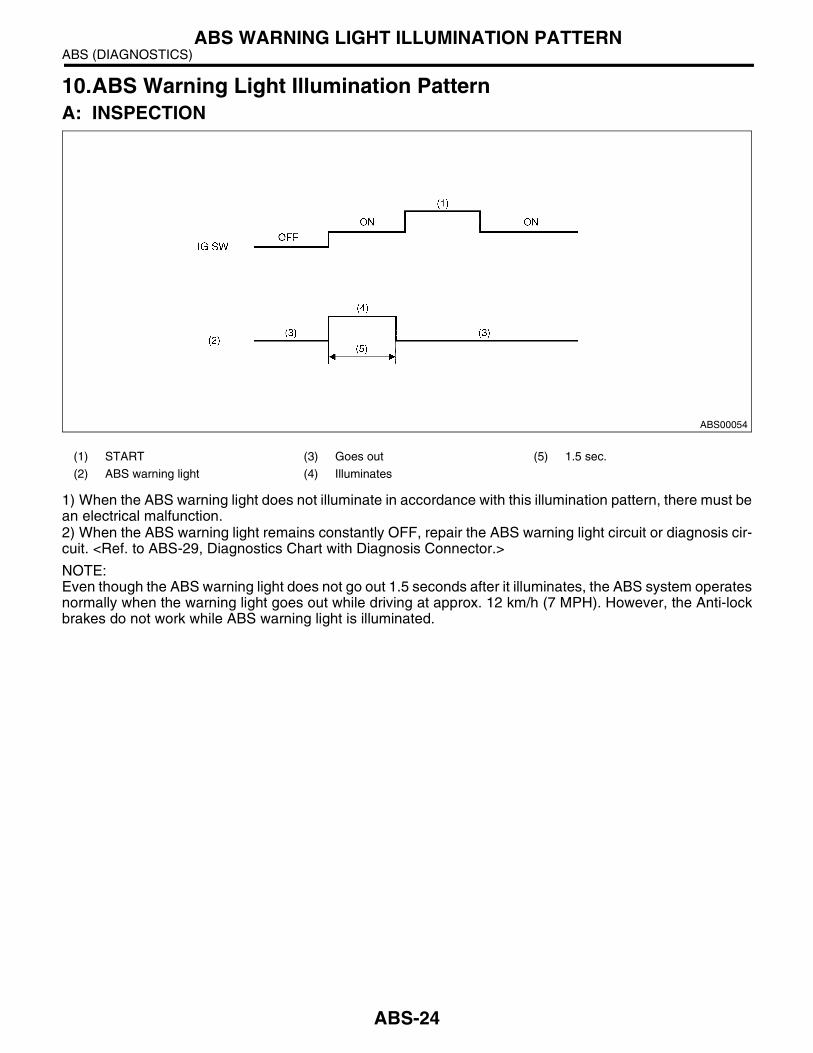
10.ABS Warning Light Illumination PatternA: INSPECTION
1) When the ABS warning light does not illuminate in accordance with this illumination pattern, there must bean electrical malfunction.2) When the ABS warning light remains constantly OFF, repair the ABS warning light circuit or diagnosis cir-cuit. <Ref. to ABS-29, Diagnostics Chart with Diagnosis Connector.>
NOTE:Even though the ABS warning light does not go out 1.5 seconds after it illuminates, the ABS system operatesnormally when the warning light goes out while driving at approx. 12 km/h (7 MPH). However, the Anti-lockbrakes do not work while ABS warning light is illuminated.
(1) START (3) Goes out (5) 1.5 sec.
(2) ABS warning light (4) Illuminates
ABS00054
ABS-24
ABS (DIAGNOSTICS)LIST OF DIAGNOSTICS TROUBLE CODE (DTC)
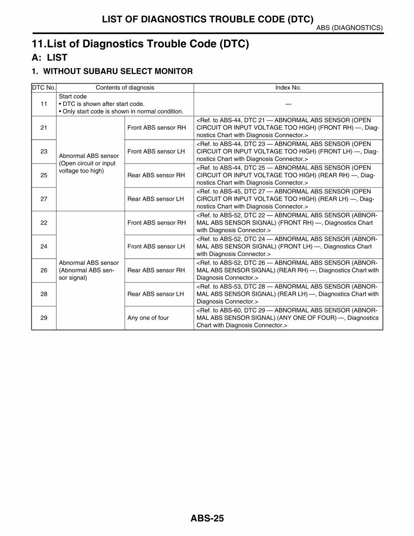
11.List of Diagnostics Trouble Code (DTC)A: LIST1. WITHOUT SUBARU SELECT MONITOR
DTC No. Contents of diagnosis Index No.
11Start code• DTC is shown after start code.• Only start code is shown in normal condition.
—
21
Abnormal ABS sensor(Open circuit or input voltage too high)
Front ABS sensor RH<Ref. to ABS-44, DTC 21 — ABNORMAL ABS SENSOR (OPEN CIRCUIT OR INPUT VOLTAGE TOO HIGH) (FRONT RH) —, Diag-nostics Chart with Diagnosis Connector.>
23 Front ABS sensor LH<Ref. to ABS-44, DTC 23 — ABNORMAL ABS SENSOR (OPEN CIRCUIT OR INPUT VOLTAGE TOO HIGH) (FRONT LH) —, Diag-nostics Chart with Diagnosis Connector.>
25 Rear ABS sensor RH<Ref. to ABS-44, DTC 25 — ABNORMAL ABS SENSOR (OPEN CIRCUIT OR INPUT VOLTAGE TOO HIGH) (REAR RH) —, Diag-nostics Chart with Diagnosis Connector.>
27 Rear ABS sensor LH<Ref. to ABS-45, DTC 27 — ABNORMAL ABS SENSOR (OPEN CIRCUIT OR INPUT VOLTAGE TOO HIGH) (REAR LH) —, Diag-nostics Chart with Diagnosis Connector.>
22
Abnormal ABS sensor(Abnormal ABS sen-sor signal)
Front ABS sensor RH<Ref. to ABS-52, DTC 22 — ABNORMAL ABS SENSOR (ABNOR-MAL ABS SENSOR SIGNAL) (FRONT RH) —, Diagnostics Chart with Diagnosis Connector.>
24 Front ABS sensor LH<Ref. to ABS-52, DTC 24 — ABNORMAL ABS SENSOR (ABNOR-MAL ABS SENSOR SIGNAL) (FRONT LH) —, Diagnostics Chart with Diagnosis Connector.>
26 Rear ABS sensor RH<Ref. to ABS-52, DTC 26 — ABNORMAL ABS SENSOR (ABNOR-MAL ABS SENSOR SIGNAL) (REAR RH) —, Diagnostics Chart with Diagnosis Connector.>
28 Rear ABS sensor LH<Ref. to ABS-53, DTC 28 — ABNORMAL ABS SENSOR (ABNOR-MAL ABS SENSOR SIGNAL) (REAR LH) —, Diagnostics Chart with Diagnosis Connector.>
29 Any one of four<Ref. to ABS-60, DTC 29 — ABNORMAL ABS SENSOR (ABNOR-MAL ABS SENSOR SIGNAL) (ANY ONE OF FOUR) —, Diagnostics Chart with Diagnosis Connector.>
ABS-25

ABS (DIAGNOSTICS)LIST OF DIAGNOSTICS TROUBLE CODE (DTC)
31
Abnormal solenoid valve circuit(s) in ABS control module and hydraulic unit
Front inlet valve RH<Ref. to ABS-66, DTC 31 — ABNORMAL INLET SOLENOID VALVE CIRCUIT(S) IN ABSCM&H/U (FRONT RH) —, Diagnostics Chart with Diagnosis Connector.>
32 Front outlet valve RH<Ref. to ABS-70, DTC 32 — ABNORMAL OUTLET SOLENOID VALVE CIRCUIT(S) IN ABSCM&H/U (FRONT RH) —, Diagnostics Chart with Diagnosis Connector.>
33 Front inlet valve LH<Ref. to ABS-66, DTC 33 — ABNORMAL INLET SOLENOID VALVE CIRCUIT(S) IN ABSCM&H/U (FRONT LH) —, Diagnostics Chart with Diagnosis Connector.>
34 Front outlet valve LH<Ref. to ABS-70, DTC 34 — ABNORMAL OUTLET SOLENOID VALVE CIRCUIT(S) IN ABSCM&H/U (FRONT LH) —, Diagnostics Chart with Diagnosis Connector.>
35 Rear inlet valve RH<Ref. to ABS-66, DTC 35 — ABNORMAL INLET SOLENOID VALVE CIRCUIT(S) IN ABSCM&H/U (REAR RH) —, Diagnostics Chart with Diagnosis Connector.>
36 Rear outlet valve RH<Ref. to ABS-70, DTC 36 — ABNORMAL OUTLET SOLENOID VALVE CIRCUIT(S) IN ABSCM&H/U (REAR RH) —, Diagnostics Chart with Diagnosis Connector.>
37 Rear inlet valve LH<Ref. to ABS-67, DTC 37 — ABNORMAL INLET SOLENOID VALVE CIRCUIT(S) IN ABSCM&H/U (REAR LH) —, Diagnostics Chart with Diagnosis Connector.>
38 Rear outlet valve LH<Ref. to ABS-71, DTC 38 — ABNORMAL OUTLET SOLENOID VALVE CIRCUIT(S) IN ABSCM&H/U (REAR LH) —, Diagnostics Chart with Diagnosis Connector.>
41 Abnormal ABS control module<Ref. to ABS-74, DTC 41 — ABNORMAL ABS CONTROL MOD-ULE —, Diagnostics Chart with Diagnosis Connector.>
42 Source voltage is abnormal.<Ref. to ABS-76, DTC 42 — SOURCE VOLTAGE IS ABNORMAL. —, Diagnostics Chart with Diagnosis Connector.>
44 A combination of AT control abnormal<Ref. to ABS-79, DTC 44 — A COMBINATION OF AT CONTROL ABNORMAL —, Diagnostics Chart with Diagnosis Connector.>
51 Abnormal valve relay<Ref. to ABS-82, DTC 51 — ABNORMAL VALVE RELAY —, Diag-nostics Chart with Diagnosis Connector.>
52 Abnormal motor and/or motor relay<Ref. to ABS-85, DTC 52 — ABNORMAL MOTOR AND/OR MOTOR RELAY —, Diagnostics Chart with Diagnosis Connector.>
54 Abnormal stop light switch<Ref. to ABS-88, DTC 54 — ABNORMAL STOP LIGHT SWITCH —, Diagnostics Chart with Diagnosis Connector.>
56 Abnormal G sensor output voltage<Ref. to ABS-90, DTC 56 — ABNORMAL G SENSOR OUTPUT VOLTAGE —, Diagnostics Chart with Diagnosis Connector.>
DTC No. Contents of diagnosis Index No.
ABS-26
ABS (DIAGNOSTICS)LIST OF DIAGNOSTICS TROUBLE CODE (DTC)
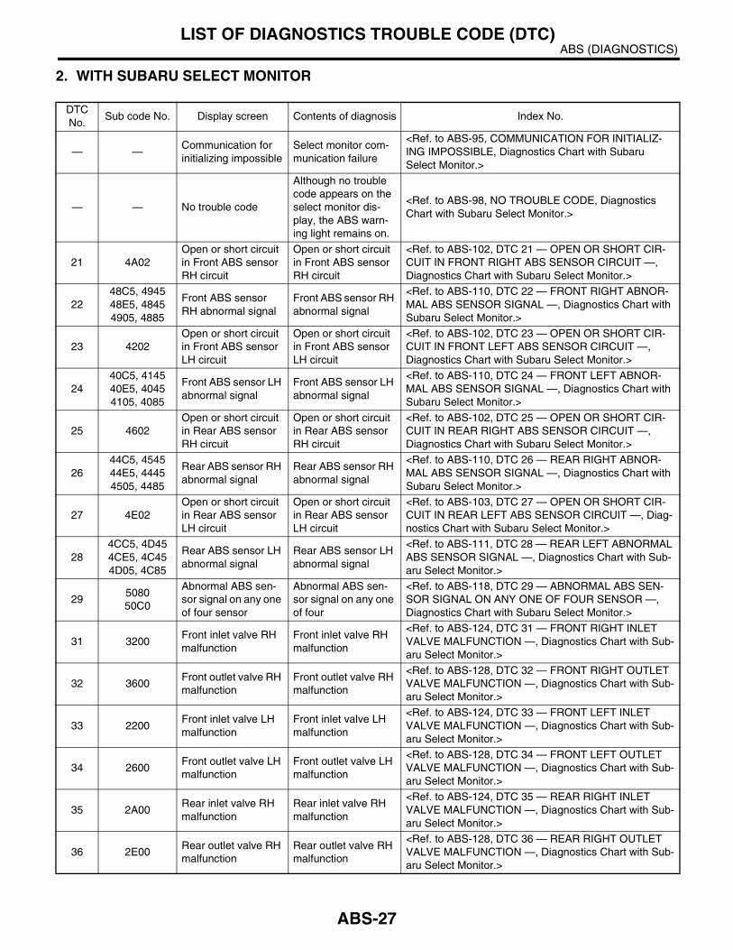
2. WITH SUBARU SELECT MONITOR
DTC No.
Sub code No. Display screen Contents of diagnosis Index No.
— —Communication for initializing impossible
Select monitor com-munication failure
<Ref. to ABS-95, COMMUNICATION FOR INITIALIZ-ING IMPOSSIBLE, Diagnostics Chart with Subaru Select Monitor.>
— — No trouble code
Although no trouble code appears on the select monitor dis-play, the ABS warn-ing light remains on.
<Ref. to ABS-98, NO TROUBLE CODE, Diagnostics Chart with Subaru Select Monitor.>
21 4A02Open or short circuit in Front ABS sensor RH circuit
Open or short circuit in Front ABS sensor RH circuit
<Ref. to ABS-102, DTC 21 — OPEN OR SHORT CIR-CUIT IN FRONT RIGHT ABS SENSOR CIRCUIT —, Diagnostics Chart with Subaru Select Monitor.>
2248C5, 494548E5, 48454905, 4885
Front ABS sensor RH abnormal signal
Front ABS sensor RH abnormal signal
<Ref. to ABS-110, DTC 22 — FRONT RIGHT ABNOR-MAL ABS SENSOR SIGNAL —, Diagnostics Chart with Subaru Select Monitor.>
23 4202Open or short circuit in Front ABS sensor LH circuit
Open or short circuit in Front ABS sensor LH circuit
<Ref. to ABS-102, DTC 23 — OPEN OR SHORT CIR-CUIT IN FRONT LEFT ABS SENSOR CIRCUIT —, Diagnostics Chart with Subaru Select Monitor.>
2440C5, 414540E5, 40454105, 4085
Front ABS sensor LH abnormal signal
Front ABS sensor LH abnormal signal
<Ref. to ABS-110, DTC 24 — FRONT LEFT ABNOR-MAL ABS SENSOR SIGNAL —, Diagnostics Chart with Subaru Select Monitor.>
25 4602Open or short circuit in Rear ABS sensor RH circuit
Open or short circuit in Rear ABS sensor RH circuit
<Ref. to ABS-102, DTC 25 — OPEN OR SHORT CIR-CUIT IN REAR RIGHT ABS SENSOR CIRCUIT —, Diagnostics Chart with Subaru Select Monitor.>
2644C5, 454544E5, 44454505, 4485
Rear ABS sensor RH abnormal signal
Rear ABS sensor RH abnormal signal
<Ref. to ABS-110, DTC 26 — REAR RIGHT ABNOR-MAL ABS SENSOR SIGNAL —, Diagnostics Chart with Subaru Select Monitor.>
27 4E02Open or short circuit in Rear ABS sensor LH circuit
Open or short circuit in Rear ABS sensor LH circuit
<Ref. to ABS-103, DTC 27 — OPEN OR SHORT CIR-CUIT IN REAR LEFT ABS SENSOR CIRCUIT —, Diag-nostics Chart with Subaru Select Monitor.>
284CC5, 4D454CE5, 4C454D05, 4C85
Rear ABS sensor LH abnormal signal
Rear ABS sensor LH abnormal signal
<Ref. to ABS-111, DTC 28 — REAR LEFT ABNORMAL ABS SENSOR SIGNAL —, Diagnostics Chart with Sub-aru Select Monitor.>
29508050C0
Abnormal ABS sen-sor signal on any one of four sensor
Abnormal ABS sen-sor signal on any one of four
<Ref. to ABS-118, DTC 29 — ABNORMAL ABS SEN-SOR SIGNAL ON ANY ONE OF FOUR SENSOR —, Diagnostics Chart with Subaru Select Monitor.>
31 3200Front inlet valve RH malfunction
Front inlet valve RH malfunction
<Ref. to ABS-124, DTC 31 — FRONT RIGHT INLET VALVE MALFUNCTION —, Diagnostics Chart with Sub-aru Select Monitor.>
32 3600Front outlet valve RH malfunction
Front outlet valve RH malfunction
<Ref. to ABS-128, DTC 32 — FRONT RIGHT OUTLET VALVE MALFUNCTION —, Diagnostics Chart with Sub-aru Select Monitor.>
33 2200Front inlet valve LH malfunction
Front inlet valve LH malfunction
<Ref. to ABS-124, DTC 33 — FRONT LEFT INLET VALVE MALFUNCTION —, Diagnostics Chart with Sub-aru Select Monitor.>
34 2600Front outlet valve LH malfunction
Front outlet valve LH malfunction
<Ref. to ABS-128, DTC 34 — FRONT LEFT OUTLET VALVE MALFUNCTION —, Diagnostics Chart with Sub-aru Select Monitor.>
35 2A00Rear inlet valve RH malfunction
Rear inlet valve RH malfunction
<Ref. to ABS-124, DTC 35 — REAR RIGHT INLET VALVE MALFUNCTION —, Diagnostics Chart with Sub-aru Select Monitor.>
36 2E00Rear outlet valve RH malfunction
Rear outlet valve RH malfunction
<Ref. to ABS-128, DTC 36 — REAR RIGHT OUTLET VALVE MALFUNCTION —, Diagnostics Chart with Sub-aru Select Monitor.>
ABS-27
ABS (DIAGNOSTICS)LIST OF DIAGNOSTICS TROUBLE CODE (DTC)
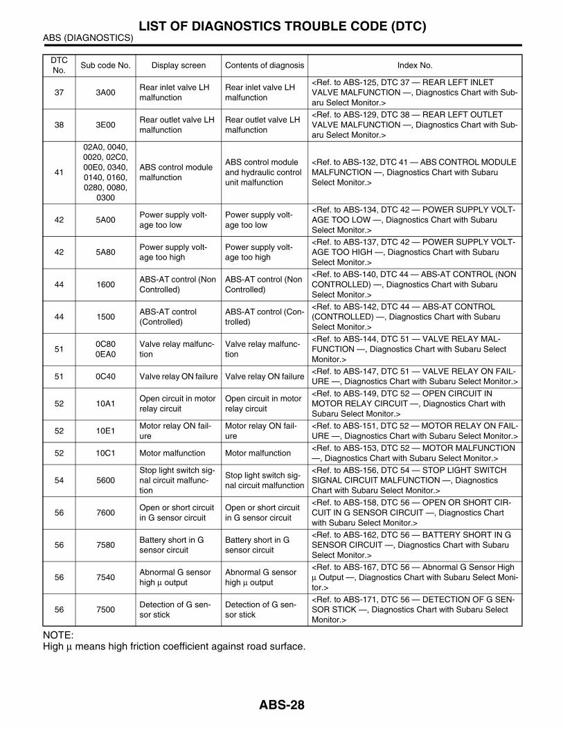
NOTE:High µ means high friction coefficient against road surface.
37 3A00Rear inlet valve LH malfunction
Rear inlet valve LH malfunction
<Ref. to ABS-125, DTC 37 — REAR LEFT INLET VALVE MALFUNCTION —, Diagnostics Chart with Sub-aru Select Monitor.>
38 3E00Rear outlet valve LH malfunction
Rear outlet valve LH malfunction
<Ref. to ABS-129, DTC 38 — REAR LEFT OUTLET VALVE MALFUNCTION —, Diagnostics Chart with Sub-aru Select Monitor.>
41
02A0, 0040, 0020, 02C0, 00E0, 0340, 0140, 0160, 0280, 0080,
0300
ABS control module malfunction
ABS control module and hydraulic control unit malfunction
<Ref. to ABS-132, DTC 41 — ABS CONTROL MODULE MALFUNCTION —, Diagnostics Chart with Subaru Select Monitor.>
42 5A00Power supply volt-age too low
Power supply volt-age too low
<Ref. to ABS-134, DTC 42 — POWER SUPPLY VOLT-AGE TOO LOW —, Diagnostics Chart with Subaru Select Monitor.>
42 5A80Power supply volt-age too high
Power supply volt-age too high
<Ref. to ABS-137, DTC 42 — POWER SUPPLY VOLT-AGE TOO HIGH —, Diagnostics Chart with Subaru Select Monitor.>
44 1600ABS-AT control (Non Controlled)
ABS-AT control (Non Controlled)
<Ref. to ABS-140, DTC 44 — ABS-AT CONTROL (NON CONTROLLED) —, Diagnostics Chart with Subaru Select Monitor.>
44 1500ABS-AT control (Controlled)
ABS-AT control (Con-trolled)
<Ref. to ABS-142, DTC 44 — ABS-AT CONTROL (CONTROLLED) —, Diagnostics Chart with Subaru Select Monitor.>
510C800EA0
Valve relay malfunc-tion
Valve relay malfunc-tion
<Ref. to ABS-144, DTC 51 — VALVE RELAY MAL-FUNCTION —, Diagnostics Chart with Subaru Select Monitor.>
51 0C40 Valve relay ON failure Valve relay ON failure<Ref. to ABS-147, DTC 51 — VALVE RELAY ON FAIL-URE —, Diagnostics Chart with Subaru Select Monitor.>
52 10A1Open circuit in motor relay circuit
Open circuit in motor relay circuit
<Ref. to ABS-149, DTC 52 — OPEN CIRCUIT IN MOTOR RELAY CIRCUIT —, Diagnostics Chart with Subaru Select Monitor.>
52 10E1Motor relay ON fail-ure
Motor relay ON fail-ure
<Ref. to ABS-151, DTC 52 — MOTOR RELAY ON FAIL-URE —, Diagnostics Chart with Subaru Select Monitor.>
52 10C1 Motor malfunction Motor malfunction<Ref. to ABS-153, DTC 52 — MOTOR MALFUNCTION —, Diagnostics Chart with Subaru Select Monitor.>
54 5600Stop light switch sig-nal circuit malfunc-tion
Stop light switch sig-nal circuit malfunction
<Ref. to ABS-156, DTC 54 — STOP LIGHT SWITCH SIGNAL CIRCUIT MALFUNCTION —, Diagnostics Chart with Subaru Select Monitor.>
56 7600Open or short circuit in G sensor circuit
Open or short circuit in G sensor circuit
<Ref. to ABS-158, DTC 56 — OPEN OR SHORT CIR-CUIT IN G SENSOR CIRCUIT —, Diagnostics Chart with Subaru Select Monitor.>
56 7580Battery short in G sensor circuit
Battery short in G sensor circuit
<Ref. to ABS-162, DTC 56 — BATTERY SHORT IN G SENSOR CIRCUIT —, Diagnostics Chart with Subaru Select Monitor.>
56 7540Abnormal G sensor high µ output
Abnormal G sensor high µ output
<Ref. to ABS-167, DTC 56 — Abnormal G Sensor High µ Output —, Diagnostics Chart with Subaru Select Moni-tor.>
56 7500Detection of G sen-sor stick
Detection of G sen-sor stick
<Ref. to ABS-171, DTC 56 — DETECTION OF G SEN-SOR STICK —, Diagnostics Chart with Subaru Select Monitor.>
DTC No.
Sub code No. Display screen Contents of diagnosis Index No.
ABS-28
ABS (DIAGNOSTICS)DIAGNOSTICS CHART WITH DIAGNOSIS CONNECTOR
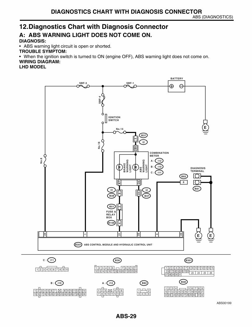
12.Diagnostics Chart with Diagnosis ConnectorA: ABS WARNING LIGHT DOES NOT COME ON.DIAGNOSIS:• ABS warning light circuit is open or shorted.TROUBLE SYMPTOM:• When the ignition switch is turned to ON (engine OFF), ABS warning light does not come on.WIRING DIAGRAM:LHD MODEL
22
ABS00199
BATTERY
IGNITIONSWITCH
SBF-3 SBF-1
SB
F-4
B37
No.14
No
.18
No
.8
i2
i10B :
i12A :
C : i11
i2
B37
BR
AK
EW
AR
NIN
GL
IGH
T
COMBINATIONMETER
DIAGNOSISTERMINAL
E
EE
5B
9
6A7
C6
124 4 23
21
B82
B81
B301
B82
B36i11C :
i10B : i12A :
1 2 3 4 5 6 7 8 9 1012 13 14 15 16 17 18 19 20 21 22 23 24
1 2 3 4 5 6 7 8 9 10 11 12 13 1415 16 17 18 19 20 21 22 23 24 25 26 27 28 29 30
1 2 3 4 5 6 7 8 9 10 111 2 3 4 5 6 7 8 9 10 11 12 13 14 1516 17 18 19 20 21 22
27 28 29 30 3123 24 25 26
AB
SW
AR
NIN
GL
IGH
T
ABS CONTROL MODULE AND HYDRAULIC CONTROL UNITB301
1 2987 103
11 12 13 144 5 6 1 2
3 4 5 6
9 23
i3
B38
B51
B158
24
FUSE &RELAYBOX
219
32
1 2 3 4 5 610 11 12 13 14 15
716
23 3019 20
22 26 27 28 29
817
24 3118
25
B38
ABS-29
ABS (DIAGNOSTICS)DIAGNOSTICS CHART WITH DIAGNOSIS CONNECTOR
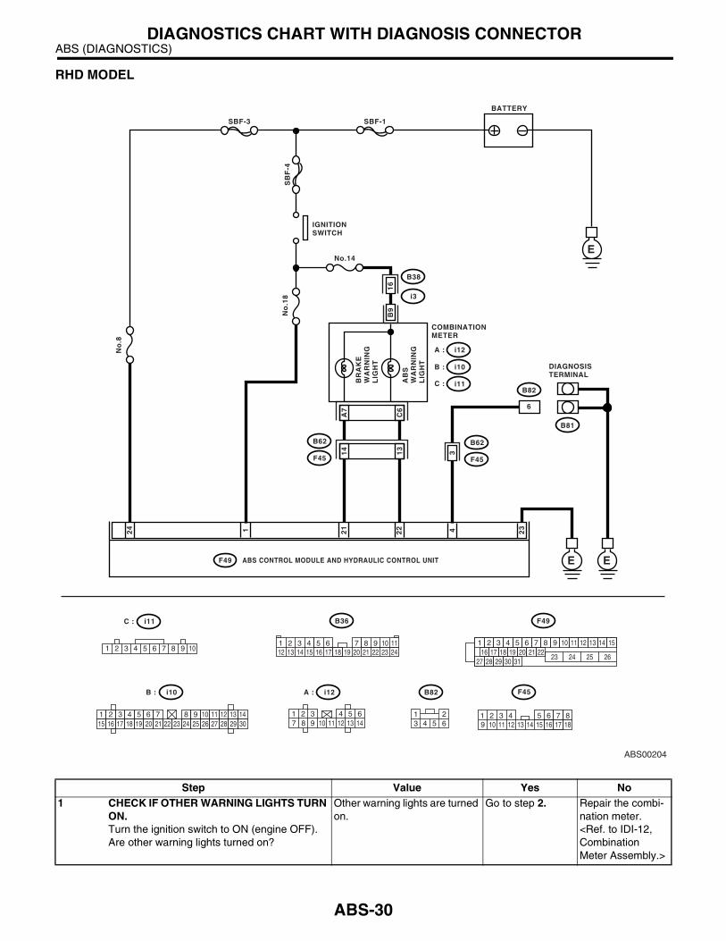
RHD MODEL
22
ABS00204
BATTERY
IGNITIONSWITCH
SBF-3 SBF-1
SB
F-4
B38
No.14
No
.18
No
.8
i3
i10B :
i12A :
C : i11
B62
F45
BR
AK
EW
AR
NIN
GL
IGH
T
COMBINATIONMETER
DIAGNOSISTERMINAL
E
EE
B9
6
A7
C6
14 13
124 4 23
21
B82
B81
F49
B82
B36i11C :
i10B : i12A :
1 2 3 4 5 6 7 8 9 10 12 13 14 15 16 17 18 19 20 21 22 23 24
1 2 3 4 5 6 7 8 9 10 11 12 13 1415 16 17 18 19 20 21 22 23 24 25 26 27 28 29 30
1 2 3 4 5 6 7 8 9 10 111 2 3 4 5 6 7 8 9 10 11 12 13 14 1516 17 18 19 20 21 22
27 28 29 30 3123 24 25 26
AB
SW
AR
NIN
GL
IGH
T
ABS CONTROL MODULE AND HYDRAULIC CONTROL UNITF49
1 2987 103
11 12 13 144 5 6 1 2
3 4 5 6
16
3B62
F45
10 11 12 13 14 15 16 17 181 2 3 4 7 85 69
F45
Step Value Yes No1 CHECK IF OTHER WARNING LIGHTS TURN
ON.Turn the ignition switch to ON (engine OFF).Are other warning lights turned on?
Other warning lights are turned on.
Go to step 2. Repair the combi-nation meter. <Ref. to IDI-12, Combination Meter Assembly.>
ABS-30
ABS (DIAGNOSTICS)DIAGNOSTICS CHART WITH DIAGNOSIS CONNECTOR
2 CHECK ABS AND BRAKE WARNING LIGHT BULB.1)Turn the ignition switch to OFF.2)Remove the combination meter.3)Remove the ABS warning light and brake warning light.Is the ABS warning light bulb open?
Valves are not blown out. Go to step 3. Replace the ABS and brake warn-ing light bulb. <Ref. to IDI-12, Combination Meter Assembly.>
3 CHECK BATTERY SHORT OF ABS AND BRAKE WARNING LIGHT HARNESS.1)Disconnect the connector (i2) or (B62) from connector (B37) or (F45).2)Measure the voltage between connector (i2) or (B62) and chassis ground.
Connector & terminalLHD: (i2) No. 23 (+) — Chassis ground (−−−−):RHD: (B62) No. 13 (+) — Chassis ground (−−−−):
Is the measured value less than specified value?
3 V Go to step 4. Repair the warning light harness.
4 CHECK BATTERY SHORT OF ABS AND BRAKE WARNING LIGHT HARNESS.1)Turn the ignition switch to ON.2)Measure the voltage between connector (i2) or (B62) and chassis ground.
Connector & terminalLHD: (i2) No. 23 (+) — Chassis ground (−−−−):RHD: (B62) No. 13 (+) — Chassis ground (−−−−):
Is the measured value less than specified value?
3 V Go to step 5. Repair the warning light harness.
5 CHECK WIRING HARNESS.1)Turn the ignition switch to OFF.2)Install the combination meter.3)Turn the ignition switch to ON.4)Measure the voltage between connector (i2) or (B62) and chassis ground.
Connector & terminalLHD: (i2) No. 23 (+) — Chassis ground (−−−−):RHD: (B62) No. 13 (+) — Chassis ground (−−−−):
Is the measured value within specified value?
10 — 15 V Go to step 6. Repair the wiring harness.
6 CHECK BATTERY SHORT OF ABS AND BRAKE WARNING LIGHT HARNESS.1)Turn the ignition switch to OFF.2)Measure the voltage between connector (B37) or (F45) and chassis ground.
Connector & terminalLHD: (B37) No. 23 (+) — Chassis ground (−−−−):RHD: (F45) No. 13 (+) — Chassis ground (−−−−):
Is the measured value less than specified value?
3 V Go to step 7. Repair the wiring harness.
Step Value Yes No
ABS-31

ABS (DIAGNOSTICS)DIAGNOSTICS CHART WITH DIAGNOSIS CONNECTOR
7 CHECK BATTERY SHORT OF ABS AND BRAKE WARNING LIGHT HARNESS.1)Turn the ignition switch to ON.2)Measure the voltage between connector (B37) or (F45) and chassis ground.
Connector & terminalLHD: (B37) No. 23 (+) — Chassis ground (−−−−):RHD: (F45) No. 13 (+) — Chassis ground (−−−−):
Is the measured value less than specified value?
3 V Go to step 8. Repair the wiring harness.
8 CHECK GROUND CIRCUIT OF ABSCM&H/U.1)Turn the ignition switch to OFF.2)Disconnect the connector from ABSCM&H/U.3)Measure the resistance between ABSCM&H/U and chassis ground.
Connector & terminalLHD: (B301) No. 23 — Chassis ground:RHD: (F49) No. 23 — Chassis ground:
Is the measured value less than specified value?
0.5 Ω Go to step 9. Repair the ABSCM&H/U ground harness.
9 CHECK WIRING HARNESS.Measure the resistance between connector (B37) or (F45) and chassis ground.
Connector & terminalLHD: (B37) No. 23 — Chassis ground:RHD: (F45) No. 13 — Chassis ground:
Is the measured value less than specified value?
0.5 Ω Go to step 10. Repair the har-ness/connector.
10 CHECK POOR CONTACT IN CONNECTORS.Turn the ignition switch to OFF.Is there poor contact in connectors between combination meter and ABSCM&H/U?
There is no poor contact. Replace the ABSCM&H/U. <Ref. to ABS-7, ABS Control Mod-ule and Hydraulic Control Unit (ABSCM&H/U).>
Repair the con-nector.
Step Value Yes No
ABS-32

ABS (DIAGNOSTICS)DIAGNOSTICS CHART WITH DIAGNOSIS CONNECTOR
B: ABS WARNING LIGHT DOES NOT GO OFF.TROUBLE SYMPTOM:• When starting the engine and while ABS warning light is kept ON.WIRING DIAGRAM:LHD MODEL
22
ABS00199
BATTERY
IGNITIONSWITCH
SBF-3 SBF-1
SB
F-4
B37
No.14
No
.18
No
.8
i2
i10B :
i12A :
C : i11
i2
B37
BR
AK
EW
AR
NIN
GL
IGH
TCOMBINATIONMETER
DIAGNOSISTERMINAL
E
EE
5B
9
6A7
C6
124 4 23
21
B82
B81
B301
B82
B36i11C :
i10B : i12A :
1 2 3 4 5 6 7 8 9 1012 13 14 15 16 17 18 19 20 21 22 23 24
1 2 3 4 5 6 7 8 9 10 11 12 13 1415 16 17 18 19 20 21 22 23 24 25 26 27 28 29 30
1 2 3 4 5 6 7 8 9 10 111 2 3 4 5 6 7 8 9 10 11 12 13 14 1516 17 18 19 20 21 22
27 28 29 30 3123 24 25 26
AB
SW
AR
NIN
GL
IGH
T
ABS CONTROL MODULE AND HYDRAULIC CONTROL UNITB301
1 2987 103
11 12 13 144 5 6 1 2
3 4 5 6
9 23
i3
B38
B51
B158
24
FUSE &RELAYBOX
219
32
1 2 3 4 5 610 11 12 13 14 15
716
23 3019 20
22 26 27 28 29
817
24 3118
25
B38
ABS-33

ABS (DIAGNOSTICS)DIAGNOSTICS CHART WITH DIAGNOSIS CONNECTOR
RHD MODEL
22
ABS00204
BATTERY
IGNITIONSWITCH
SBF-3 SBF-1
SB
F-4
B38
No.14
No
.18
No
.8
i3
i10B :
i12A :
C : i11
B62
F45
BR
AK
EW
AR
NIN
GL
IGH
T
COMBINATIONMETER
DIAGNOSISTERMINAL
E
EE
B9
6
A7
C6
14 13
124 4 23
21
B82
B81
F49
B82
B36i11C :
i10B : i12A :
1 2 3 4 5 6 7 8 9 10 12 13 14 15 16 17 18 19 20 21 22 23 24
1 2 3 4 5 6 7 8 9 10 11 12 13 1415 16 17 18 19 20 21 22 23 24 25 26 27 28 29 30
1 2 3 4 5 6 7 8 9 10 111 2 3 4 5 6 7 8 9 10 11 12 13 14 1516 17 18 19 20 21 22
27 28 29 30 3123 24 25 26
AB
SW
AR
NIN
GL
IGH
T
ABS CONTROL MODULE AND HYDRAULIC CONTROL UNITF49
1 2987 103
11 12 13 144 5 6 1 2
3 4 5 6
16
3B62
F45
10 11 12 13 14 15 16 17 181 2 3 4 7 85 69
F45
Step Value Yes No1 CHECK INSTALLATION OF ABSCM&H/U
CONNECTOR.Turn the ignition switch to OFF.Is the ABSCM&H/U connector inserted into ABSCM until the clamp locks onto it?
Connector is inserted securely. Go to step 2. Insert the ABSCM&H/U con-nector into ABSCM&H/U until the clamp locks onto it.
ABS-34
ABS (DIAGNOSTICS)DIAGNOSTICS CHART WITH DIAGNOSIS CONNECTOR
2 CHECK DIAGNOSIS TERMINAL.Measure the resistance between diagnosis ter-minals (B81) and chassis ground.
TerminalsDiagnosis terminal (A) — Chassis ground:Diagnosis terminal (B) — Chassis ground:
Is the measured value less than specified value?
0.5 Ω Go to step 3. Repair the diagno-sis terminal har-ness.
3 CHECK DIAGNOSIS LINE.1)Connect the diagnosis terminal (B81) to diagnosis connector (B82) No. 6.2)Disconnect the connector from ABSCM&H/U.3)Measure the resistance between ABSCM&H/U connector and chassis ground.
Connector & terminalLHD: (B301) No. 4 — Chassis ground:RHD: (F49) No. 4 — Chassis ground:
Is the measured value less than specified value?
0.5 Ω Go to step 4. Repair the har-ness connector between ABSCM&H/U and diagnosis connec-tor.
4 CHECK GENERATOR.1)Start the engine.2)Idle the engine.3)Measure the voltage between generator and chassis ground.
TerminalGenerator B terminal (+) — Chassis ground (−−−−):
Is the measured value within specified value?
10 — 15 V Go to step 5. Repair the genera-tor. <Ref. to SC(SOHC)-15, Generator.>
5 CHECK BATTERY TERMINAL.Turn the ignition switch to OFF.Is there poor contact at battery terminal?
There is no poor contact. Go to step 6. Repair or tighten the battery termi-nal.
6 CHECK POWER SUPPLY OF ABSCM.1)Start the engine.2)Idle the engine.3)Measure the voltage between ABSCM&H/U connector and chassis ground.
Connector & terminalLHD: (B301) No. 1 (+) — Chassis ground (−−−−):RHD: (F49) No. 1 (+) — Chassis ground (−−−−):
Is the measured value within specified value?
10 — 15 V Go to step 7. Repair the ABSCM&H/U power supply cir-cuit.
7 CHECK WIRING HARNESS.1)Disconnect the connector (i2) or (B62) from connector (B37) or (F45).2)Turn ignition switch to ON.Does the ABS warning light turn on?
ABS warning light does not turn on.
Go to step 8. Repair the front or body wiring har-ness.
8 CHECK PROJECTION AT ABSCM&H/U.1)Turn the ignition switch to OFF.2)Check for damage at the ABSCM&H/U ter-minal.Is there damage on terminal?
There is no damage on termi-nal.
Go to step 9. Replace the ABSCM&H/U. <Ref. to ABS-7, ABS Control Mod-ule and Hydraulic Control Unit (ABSCM&H/U).>
Step Value Yes No
ABS-35

ABS (DIAGNOSTICS)DIAGNOSTICS CHART WITH DIAGNOSIS CONNECTOR
9 CHECK ABSCM&H/U.Measure the resistance between ABSCM&H/U terminals.
TerminalNo. 22 — No. 23:
Is the measured value more than specified value?
1 MΩ Go to step 10. Replace the ABSCM&H/U. <Ref. to ABS-7, ABS Control Mod-ule and Hydraulic Control Unit (ABSCM&H/U).>
10 CHECK WIRING HARNESS.Measure the resistance between connector (B37) or (F45) and chassis ground.
Connector & terminalLHD: (B37) No. 23 — Chassis ground:RHD: (F45) No. 13 — Chassis ground:
Is the measured value less than specified value?
0.5 Ω Go to step 11. Repair the har-ness.
11 CHECK WIRING HARNESS.1)Connect the connector to ABSCM&H/U.2)Measure the resistance between connector (B37) or (F45) and chassis ground.
Connector & terminalLHD: (B37) No. 23 — Chassis ground:RHD: (F45) No. 13 — Chassis ground:
Is the measured value more than specified value?
1 MΩ Go to step 12. Repair the har-ness.
12 CHECK POOR CONTACT IN ABSCM&H/U CONNECTOR.Is there poor contact in ABSCM&H/U connec-tor?
There is no poor contact. Replace the ABSCM&H/U. <Ref. to ABS-7, ABS Control Mod-ule and Hydraulic Control Unit (ABSCM&H/U).>
Repair the con-nector.
Step Value Yes No
ABS-36

ABS (DIAGNOSTICS)DIAGNOSTICS CHART WITH DIAGNOSIS CONNECTOR
C: ABS AND BRAKE WARNING LIGHT DO NOT GO OFF.DIAGNOSIS:• ABS warning light circuit is open or shorted.• Brake warning light circuit is shorted.• Faulty sensor/connectorTROUBLE SYMPTOM:• When starting the engine, ABS warning light is kept ON.• After starting the engine, brake warning light is kept ON, even if the parking brake lever has been released.
ABS-37
ABS (DIAGNOSTICS)DIAGNOSTICS CHART WITH DIAGNOSIS CONNECTOR
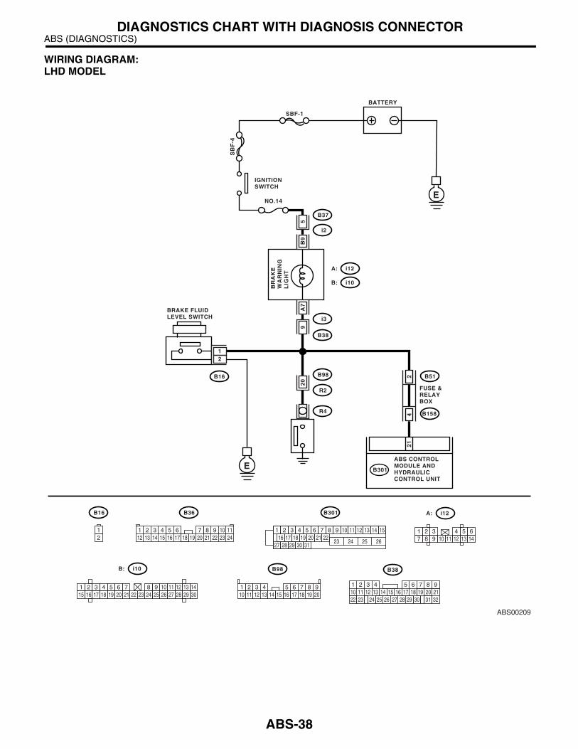
WIRING DIAGRAM:LHD MODEL
ABS00209
E
SBF-1
SB
F-4
BATTERY
E
NO.14
21
B301
B301
B37
i2
B38
B36
B16
B16
i3
B98
R2
R4
i12A:
i10B:
i12
B98
A:
i10B:
ABS CONTROLMODULE ANDHYDRAULICCONTROL UNIT
IGNITIONSWITCH
BRAKE FLUIDLEVEL SWITCH
BR
AK
EW
AR
NIN
GL
IGH
T
5B
92
0A
79
12
12
3 41 2 8 9 10 1112 13 14 15 16 17 18 19 20 21 22 23 24
5 6 7 1 2 3 4 5 6 7 8 9 10 11 12 13 14 1516 17 18 19 20 21 22
27 28 29 30 3123 24 25 26
1 2 3 4 5 6 7 8 9 10 11 12 13 1415 16 17 18 19 20 21 22 23 24 25 26 27 28 29 30
1 2 3 4 5 67 8 9 10 11 12 13 14
2 3 4 5 6 7 8 911 12 13 14 17 18 19 20
110 15 16
B51
B1582
4
FUSE &RELAYBOX
219
32
1 2 3 4 5 610 11 12 13 14 15
716
23 3019 20
22 26 27 28 29
817
24 3118
25
B38
ABS-38

ABS (DIAGNOSTICS)DIAGNOSTICS CHART WITH DIAGNOSIS CONNECTOR
RHD MODEL
Step Value Yes No1 CHECK BRAKE FLUID AMOUNT.
Check the amount of brake fluid in reservoir tank of master cylinder.Is the brake fluid amount within specified value?
Brake fluid amount is between "MAX" line and "MIN" line.
Go to step 2. Fill the brake fluid to specified amount.
ABS00214
E
SBF-1
SB
F-4
BATTERY
E
NO.14
21
B49
B301
B38
i3
B38
B36
B16
B16
i3
B98
R2
R4
i12A:
i10B:
i12A: i10B:
ABS CONTROLMODULE ANDHYDRAULICCONTROL UNIT
IGNITIONSWITCH
BRAKE FLUIDLEVEL SWITCH
BR
AK
EW
AR
NIN
GL
IGH
T
16
B9
32
A7
3
12
12
3 41 2 8 9 10 1112 13 14 15 16 17 18 19 20 21 22 23 24
5 6 7 1 2 3 4 5 6 7 8 9 10 11 12 13 14 1516 17 18 19 20 21 22
27 28 29 30 3123 24 25 26
1 2 3 4 5 6 7 8 9 10 11 12 13 1415 16 17 18 19 20 21 22 23 24 25 26 27 28 29 30
1 2 3 4 5 67 8 9 10 11 12 13 14
B62
F45
14
10 11 12 13 14 15 16 17 181 2 3 4 7 85 69
F45
219
32
1 2 3 4 5 610 11 12 13 14 15
716
23 3019 20
22 26 27 28 29
817
24 3118
25
B98 i3
ABS-39

ABS (DIAGNOSTICS)DIAGNOSTICS CHART WITH DIAGNOSIS CONNECTOR
2 CHECK BRAKE FLUID LEVEL SWITCH.1)Disconnect the level switch connector (B16) from master cylinder.2)Measure the resistance of master cylinder terminals.
TerminalsNo.1 — No.2:
Is the measured value more than specified value?
1 MΩ Go to step 3. Replace the mas-ter cylinder.
3 CHECK PARKING BRAKE SWITCH.1)Disconnect the connector (R4) from parking brake switch.2)Release the parking brake switch.3)Measure the resistance between parking brake switch terminal and chassis ground.Is the measured value more than specified value?
1 MΩ Go to step 4. Replace the park-ing brake switch.
4 CHECK GROUND SHORT OF HARNESS.1)Disconnect the connector form ABSCM & H/U.2)Disconnect the connector (i12) from combi-nation meter.3)Turn the ignition switch to ON.Does the brake warning light go off?
Brake warning light goes off. Go to step 5. Repair the har-ness.
5 CHECK POOR CONTACT IN ABSCM & H/U.Is there poor contact in ABSCM & H/U connec-tor?
There is no poor contact. Replace the ABSCM & H/U.<Ref. to ABS-7, ABS Control Mod-ule and Hydraulic Control Unit (ABSCM&H/U).>
Repair the con-nector.
Step Value Yes No
ABS-40

ABS (DIAGNOSTICS)DIAGNOSTICS CHART WITH DIAGNOSIS CONNECTOR
D: TROUBLE CODE DOES NOT APPEAR.DIAGNOSIS:• Diagnosis circuit is open.TROUBLE SYMPTOM:• The ABS warning light turns on or off normally but the start code cannot be read out in diagnostic mode.WIRING DIAGRAM:LHD MODEL
22
ABS00199
BATTERY
IGNITIONSWITCH
SBF-3 SBF-1
SB
F-4
B37
No.14
No
.18
No
.8
i2
i10B :
i12A :
C : i11
i2
B37
BR
AK
EW
AR
NIN
GL
IGH
T
COMBINATIONMETER
DIAGNOSISTERMINAL
E
EE
5B
9
6A7
C6
124 4 23
21
B82
B81
B301
B82
B36i11C :
i10B : i12A :
1 2 3 4 5 6 7 8 9 1012 13 14 15 16 17 18 19 20 21 22 23 24
1 2 3 4 5 6 7 8 9 10 11 12 13 1415 16 17 18 19 20 21 22 23 24 25 26 27 28 29 30
1 2 3 4 5 6 7 8 9 10 111 2 3 4 5 6 7 8 9 10 11 12 13 14 1516 17 18 19 20 21 22
27 28 29 30 3123 24 25 26
AB
SW
AR
NIN
GL
IGH
T
ABS CONTROL MODULE AND HYDRAULIC CONTROL UNITB301
1 2987 103
11 12 13 144 5 6 1 2
3 4 5 6
9 23
i3
B38
B51
B158
24
FUSE &RELAYBOX
219
32
1 2 3 4 5 610 11 12 13 14 15
716
23 3019 20
22 26 27 28 29
817
24 3118
25
B38
ABS-41

ABS (DIAGNOSTICS)DIAGNOSTICS CHART WITH DIAGNOSIS CONNECTOR
RHD MODEL
22
ABS00204
BATTERY
IGNITIONSWITCH
SBF-3 SBF-1
SB
F-4
B38
No.14
No
.18
No
.8
i3
i10B :
i12A :
C : i11
B62
F45
BR
AK
EW
AR
NIN
GL
IGH
T
COMBINATIONMETER
DIAGNOSISTERMINAL
E
EE
B9
6
A7
C6
14 13
124 4 23
21
B82
B81
F49
B82
B36i11C :
i10B : i12A :
1 2 3 4 5 6 7 8 9 10 12 13 14 15 16 17 18 19 20 21 22 23 24
1 2 3 4 5 6 7 8 9 10 11 12 13 1415 16 17 18 19 20 21 22 23 24 25 26 27 28 29 30
1 2 3 4 5 6 7 8 9 10 111 2 3 4 5 6 7 8 9 10 11 12 13 14 1516 17 18 19 20 21 22
27 28 29 30 3123 24 25 26
AB
SW
AR
NIN
GL
IGH
T
ABS CONTROL MODULE AND HYDRAULIC CONTROL UNITF49
1 2987 103
11 12 13 144 5 6 1 2
3 4 5 6
16
3B62
F45
10 11 12 13 14 15 16 17 181 2 3 4 7 85 69
F45
ABS-42
ABS (DIAGNOSTICS)DIAGNOSTICS CHART WITH DIAGNOSIS CONNECTOR
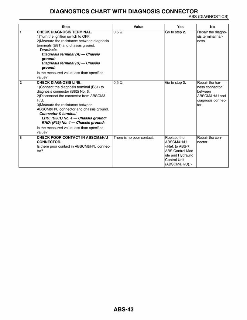
Step Value Yes No1 CHECK DIAGNOSIS TERMINAL.
1)Turn the ignition switch to OFF.2)Measure the resistance between diagnosis terminals (B81) and chassis ground.
TerminalsDiagnosis terminal (A) — Chassis ground:Diagnosis terminal (B) — Chassis ground:
Is the measured value less than specified value?
0.5 Ω Go to step 2. Repair the diagno-sis terminal har-ness.
2 CHECK DIAGNOSIS LINE.1)Connect the diagnosis terminal (B81) to diagnosis connector (B82) No. 6.2)Disconnect the connector from ABSCM&H/U.3)Measure the resistance between ABSCM&H/U connector and chassis ground.
Connector & terminalLHD: (B301) No. 4 — Chassis ground:RHD: (F49) No. 4 — Chassis ground:
Is the measured value less than specified value?
0.5 Ω Go to step 3. Repair the har-ness connector between ABSCM&H/U and diagnosis connec-tor.
3 CHECK POOR CONTACT IN ABSCM&H/U CONNECTOR.Is there poor contact in ABSCM&H/U connec-tor?
There is no poor contact. Replace the ABSCM&H/U. <Ref. to ABS-7, ABS Control Mod-ule and Hydraulic Control Unit (ABSCM&H/U).>
Repair the con-nector.
ABS-43

ABS (DIAGNOSTICS)DIAGNOSTICS CHART WITH DIAGNOSIS CONNECTOR
E: DTC 21— ABNORMAL ABS SENSOR (OPEN CIRCUIT OR INPUT VOLTAGE TOO HIGH) (FRONT RH) —
NOTE:For the diagnostic procedure, refer to DTC 27. <Ref. to ABS-45, DTC 27 — ABNORMAL ABS SENSOR(OPEN CIRCUIT OR INPUT VOLTAGE TOO HIGH) (REAR LH) —, Diagnostics Chart with Diagnosis Con-nector.>
F: DTC 23 — ABNORMAL ABS SENSOR (OPEN CIRCUIT OR INPUT VOLTAGE TOO HIGH) (FRONT LH) —
NOTE:For the diagnostic procedure, refer to DTC 27. <Ref. to ABS-45, DTC 27 — ABNORMAL ABS SENSOR(OPEN CIRCUIT OR INPUT VOLTAGE TOO HIGH) (REAR LH) —, Diagnostics Chart with Diagnosis Con-nector.>
G: DTC 25 — ABNORMAL ABS SENSOR (OPEN CIRCUIT OR INPUT VOLTAGE TOO HIGH) (REAR RH) —
NOTE:For the diagnostic procedure, refer to DTC 27. <Ref. to ABS-45, DTC 27 — ABNORMAL ABS SENSOR(OPEN CIRCUIT OR INPUT VOLTAGE TOO HIGH) (REAR LH) —, Diagnostics Chart with Diagnosis Con-nector.>
ABS-44
ABS (DIAGNOSTICS)DIAGNOSTICS CHART WITH DIAGNOSIS CONNECTOR
H: DTC 27 — ABNORMAL ABS SENSOR (OPEN CIRCUIT OR INPUT VOLTAGE TOO HIGH) (REAR LH) —
DIAGNOSIS:• Faulty ABS sensor (Broken wire, input voltage too high)• Faulty harness connectorTROUBLE SYMPTOM:• ABS does not operate.
ABS-45

ABS (DIAGNOSTICS)DIAGNOSTICS CHART WITH DIAGNOSIS CONNECTOR
WIRING DIAGRAM:LHD MODEL
ABS00219
ABS CONTROL MODULE AND HYDRAULIC CONTROL UNIT
SHIELD JOINTCONNECTOR
B301
15
14
109 87 23
F103
REAR ABSSENSOR RH
B98
R72
R2
E
17 6
3
54
19
1887
REAR ABSSENSOR LH
R73
FRONT ABSSENSOR RH
B6
21
21
TW
IST
ED
WIR
E
TW
IST
ED
WIR
E
21
FRONT ABSSENSOR LH
F94
B321
F103
F103 B98
B6
F94 R72
R73
21
2 1
B301
1 2 3 4 5 6 7 8 9 10 11 12 13 14 1516 17 18 19 20 21 22
27 28 29 30 3123 24 25 26
12
11
1 2 3 4 5 6 7 8 910 11 12 13 14 15 16 17 18 19 20
1 2 3 45 6 7 8
2 1
ABS-46
ABS (DIAGNOSTICS)DIAGNOSTICS CHART WITH DIAGNOSIS CONNECTOR
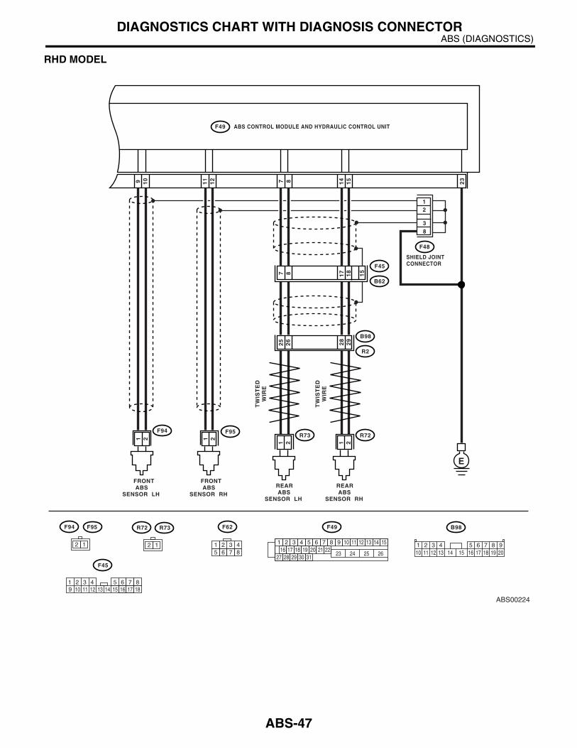
RHD MODEL
ABS00224
ABS CONTROL MODULE AND HYDRAULIC CONTROL UNIT
SHIELD JOINTCONNECTOR
F49
15
14
109 87 23
F48
REAR ABSSENSOR RH
B98
R72
R2
E
12
29
28
26
25
REAR ABSSENSOR LH
R73
FRONT ABSSENSOR RH
F95
21
21
TW
IST
ED
WIR
E
TW
IST
ED
WIR
E
21
FRONT ABSSENSOR LH
F94
F62 B98F95F94 R72 R73
21
2 1
F49
1 2 3 4 5 6 7 8 9 10 11 12 13 14 1516 17 18 19 20 21 22
27 28 29 30 3123 24 25 26
12
11
1 2 3 4 5 6 7 8 910 11 12 13 14 15 16 17 18 19 20
1 2 3 45 6 7 8
2 1
10 11 12 13 14 15 16 17 181 2 3 4 7 85 69
F45
F45
B62
18
1787 15
38
ABS-47

ABS (DIAGNOSTICS)DIAGNOSTICS CHART WITH DIAGNOSIS CONNECTOR
Step Value Yes No1 CHECK ABS SENSOR.
1)Turn the ignition switch to OFF.2)Disconnect the connector from ABS sensor.3)Measure the resistance of ABS sensor con-nector terminals while shaking the harness lightly.
TerminalFront RH No. 1 — No. 2:Front LH No. 1 — No. 2:Rear RH No. 1 — No. 2:Rear LH No. 1 — No. 2:
Is the measured value within specified value?
Front: 1 — 1.5 kΩRear: 1.025 — 1.265 kΩ
Go to step 2. Replace the ABS sensor. Front: <Ref. to ABS-14, Front ABS Sen-sor.> Rear: <Ref. to ABS-17, Rear ABS Sensor.>
2 CHECK BATTERY SHORT OF ABS SEN-SOR.1)Disconnect the connector from ABSCM&H/U.2)Measure the voltage between ABS sensor and chassis ground.
TerminalFront RH No. 1 (+) — Chassis ground (−−−−):Front LH No. 1 (+) — Chassis ground (−−−−):Rear RH No. 1 (+) — Chassis ground (−−−−):Rear LH No. 1 (+) — Chassis ground (−−−−):
Is the measured value less than specified value?
1 V Go to step 3. Replace the ABS sensor. Front: <Ref. to ABS-14, Front ABS Sen-sor.> Rear: <Ref. to ABS-17, Rear ABS Sensor.>
3 CHECK BATTERY SHORT OF ABS SEN-SOR.1)Turn the ignition switch to ON.2)Measure the voltage between ABS sensor and chassis ground.
TerminalFront RH No. 1 (+) — Chassis ground (−−−−):Front LH No. 1 (+) — Chassis ground (−−−−):Rear RH No. 1 (+) — Chassis ground (−−−−):Rear LH No. 1 (+) — Chassis ground (−−−−):
Is the measured value less than specified value?
1 V Go to step 4. Replace the ABS sensor. Front: <Ref. to ABS-14, Front ABS Sen-sor.> Rear: <Ref. to ABS-17, Rear ABS Sensor.>
4 CHECK HARNESS/CONNECTOR BETWEEN ABSCM&H/U AND ABS SENSOR.1)Turn the ignition switch to OFF.2)Connect the connector to ABS sensor.3)Measure the resistance between ABSCM&H/U connector terminals.
Connector & terminalDTC 21
LHD: (B301) No. 11 — No. 12:RHD: (F49) No. 11 — No. 12:
DTC 23LHD:(B301) No. 9 — No. 10:RHD: (F49) No. 9 — No. 10:
DTC 25LHD:(B301) No. 14 — No. 15:RHD: (F49) No. 14 — No. 15:
DTC 27LHD:(B301) No. 7 — No. 8:RHD: (F49) No. 7 — No. 8:
Is the measured value within specified value?
Front: 1 — 1.5 kΩRear: 1.025 — 1.265 kΩ
Go to step 5. Repair the har-ness/connector between ABSCM&H/U and ABS sensor.
ABS-48
ABS (DIAGNOSTICS)DIAGNOSTICS CHART WITH DIAGNOSIS CONNECTOR
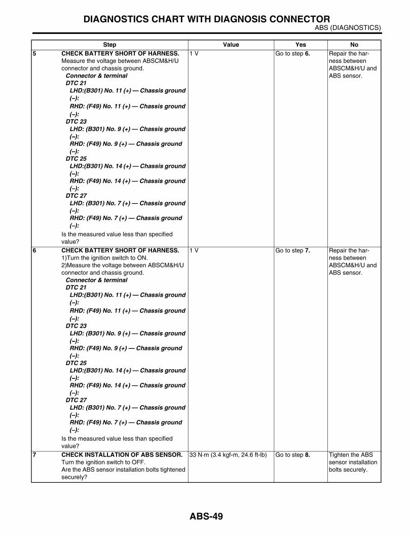
5 CHECK BATTERY SHORT OF HARNESS.Measure the voltage between ABSCM&H/U connector and chassis ground.
Connector & terminalDTC 21
LHD:(B301) No. 11 (+) — Chassis ground (−−−−):RHD: (F49) No. 11 (+) — Chassis ground (−−−−):
DTC 23LHD: (B301) No. 9 (+) — Chassis ground (−−−−):RHD: (F49) No. 9 (+) — Chassis ground (−−−−):
DTC 25LHD:(B301) No. 14 (+) — Chassis ground (−−−−):RHD: (F49) No. 14 (+) — Chassis ground (−−−−):
DTC 27LHD: (B301) No. 7 (+) — Chassis ground (−−−−):RHD: (F49) No. 7 (+) — Chassis ground (−−−−):
Is the measured value less than specified value?
1 V Go to step 6. Repair the har-ness between ABSCM&H/U and ABS sensor.
6 CHECK BATTERY SHORT OF HARNESS.1)Turn the ignition switch to ON.2)Measure the voltage between ABSCM&H/U connector and chassis ground.
Connector & terminalDTC 21
LHD:(B301) No. 11 (+) — Chassis ground (−−−−):RHD: (F49) No. 11 (+) — Chassis ground (−−−−):
DTC 23LHD: (B301) No. 9 (+) — Chassis ground (−−−−):RHD: (F49) No. 9 (+) — Chassis ground (−−−−):
DTC 25LHD:(B301) No. 14 (+) — Chassis ground (−−−−):RHD: (F49) No. 14 (+) — Chassis ground (−−−−):
DTC 27LHD: (B301) No. 7 (+) — Chassis ground (−−−−):RHD: (F49) No. 7 (+) — Chassis ground (−−−−):
Is the measured value less than specified value?
1 V Go to step 7. Repair the har-ness between ABSCM&H/U and ABS sensor.
7 CHECK INSTALLATION OF ABS SENSOR.Turn the ignition switch to OFF.Are the ABS sensor installation bolts tightened securely?
33 N·m (3.4 kgf-m, 24.6 ft-lb) Go to step 8. Tighten the ABS sensor installation bolts securely.
Step Value Yes No
ABS-49
ABS (DIAGNOSTICS)DIAGNOSTICS CHART WITH DIAGNOSIS CONNECTOR
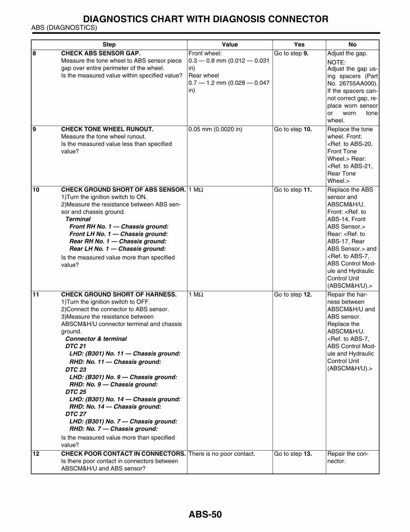
8 CHECK ABS SENSOR GAP.Measure the tone wheel to ABS sensor piece gap over entire perimeter of the wheel.Is the measured value within specified value?
Front wheel:0.3 — 0.8 mm (0.012 — 0.031 in)Rear wheel0.7 — 1.2 mm (0.028 — 0.047 in)
Go to step 9. Adjust the gap.
NOTE:Adjust the gap us-ing spacers (PartNo. 26755AA000).If the spacers can-not correct gap, re-place worn sensoror worn tonewheel.
9 CHECK TONE WHEEL RUNOUT.Measure the tone wheel runout.Is the measured value less than specified value?
0.05 mm (0.0020 in) Go to step 10. Replace the tone wheel. Front: <Ref. to ABS-20, Front Tone Wheel.> Rear: <Ref. to ABS-21, Rear Tone Wheel.>
10 CHECK GROUND SHORT OF ABS SENSOR.1)Turn the ignition switch to ON.2)Measure the resistance between ABS sen-sor and chassis ground.
TerminalFront RH No. 1 — Chassis ground:Front LH No. 1 — Chassis ground:Rear RH No. 1 — Chassis ground:Rear LH No. 1 — Chassis ground:
Is the measured value more than specified value?
1 MΩ Go to step 11. Replace the ABS sensor and ABSCM&H/U. Front: <Ref. to ABS-14, Front ABS Sensor.> Rear: <Ref. to ABS-17, Rear ABS Sensor.> and <Ref. to ABS-7, ABS Control Mod-ule and Hydraulic Control Unit (ABSCM&H/U).>
11 CHECK GROUND SHORT OF HARNESS.1)Turn the ignition switch to OFF.2)Connect the connector to ABS sensor.3)Measure the resistance between ABSCM&H/U connector terminal and chassis ground.
Connector & terminalDTC 21
LHD: (B301) No. 11 — Chassis ground:RHD: No. 11 — Chassis ground:
DTC 23LHD: (B301) No. 9 — Chassis ground:RHD: No. 9 — Chassis ground:
DTC 25LHD: (B301) No. 14 — Chassis ground:RHD: No. 14 — Chassis ground:
DTC 27LHD: (B301) No. 7 — Chassis ground:RHD: No. 7 — Chassis ground:
Is the measured value more than specified value?
1 MΩ Go to step 12. Repair the har-ness between ABSCM&H/U and ABS sensor.Replace the ABSCM&H/U. <Ref. to ABS-7, ABS Control Mod-ule and Hydraulic Control Unit (ABSCM&H/U).>
12 CHECK POOR CONTACT IN CONNECTORS.Is there poor contact in connectors between ABSCM&H/U and ABS sensor?
There is no poor contact. Go to step 13. Repair the con-nector.
Step Value Yes No
ABS-50
ABS (DIAGNOSTICS)DIAGNOSTICS CHART WITH DIAGNOSIS CONNECTOR
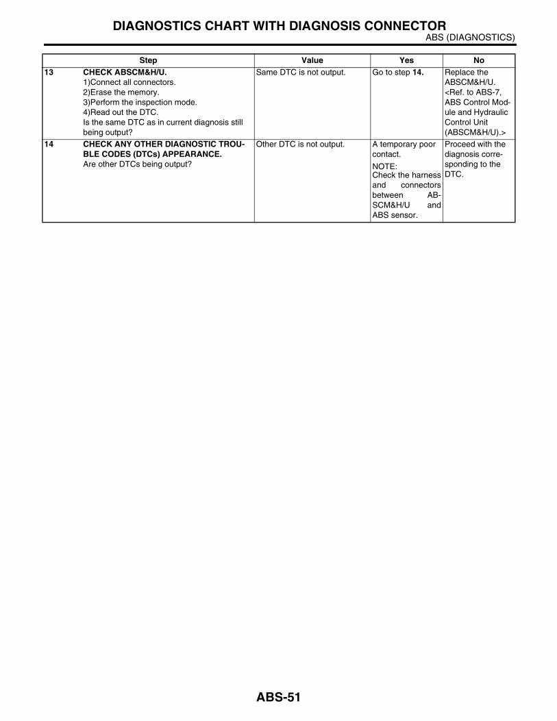
13 CHECK ABSCM&H/U.1)Connect all connectors.2)Erase the memory.3)Perform the inspection mode.4)Read out the DTC.Is the same DTC as in current diagnosis still being output?
Same DTC is not output. Go to step 14. Replace the ABSCM&H/U. <Ref. to ABS-7, ABS Control Mod-ule and Hydraulic Control Unit (ABSCM&H/U).>
14 CHECK ANY OTHER DIAGNOSTIC TROU-BLE CODES (DTCs) APPEARANCE.Are other DTCs being output?
Other DTC is not output. A temporary poor contact.
NOTE:Check the harnessand connectorsbetween AB-SCM&H/U andABS sensor.
Proceed with the diagnosis corre-sponding to the DTC.
Step Value Yes No
ABS-51
ABS (DIAGNOSTICS)DIAGNOSTICS CHART WITH DIAGNOSIS CONNECTOR
I: DTC 22 — ABNORMAL ABS SENSOR (ABNORMAL ABS SENSOR SIGNAL) (FRONT RH) —
NOTE:For the diagnostic procedure, refer to DTC 28. <Ref. to ABS-53, DTC 28 — ABNORMAL ABS SENSOR (AB-NORMAL ABS SENSOR SIGNAL) (REAR LH) —, Diagnostics Chart with Diagnosis Connector.>
J: DTC 24 — ABNORMAL ABS SENSOR (ABNORMAL ABS SENSOR SIGNAL) (FRONT LH) —
NOTE:For the diagnostic procedure, refer to DTC 28. <Ref. to ABS-53, DTC 28 — ABNORMAL ABS SENSOR (AB-NORMAL ABS SENSOR SIGNAL) (REAR LH) —, Diagnostics Chart with Diagnosis Connector.>
K: DTC 26 — ABNORMAL ABS SENSOR (ABNORMAL ABS SENSOR SIGNAL) (REAR RH) —
NOTE:For the diagnostic procedure, refer to DTC 28. <Ref. to ABS-53, DTC 28 — ABNORMAL ABS SENSOR (AB-NORMAL ABS SENSOR SIGNAL) (REAR LH) —, Diagnostics Chart with Diagnosis Connector.>
ABS-52
ABS (DIAGNOSTICS)DIAGNOSTICS CHART WITH DIAGNOSIS CONNECTOR
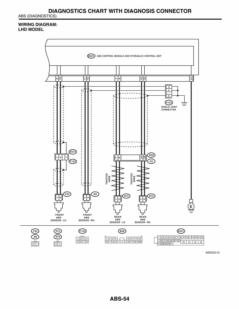
L: DTC 28 — ABNORMAL ABS SENSOR (ABNORMAL ABS SENSOR SIGNAL) (REAR LH) —
DIAGNOSIS:• Faulty ABS sensor signal (noise, irregular signal, etc.)• Faulty harness/connectorTROUBLE SYMPTOM:• ABS does not operate.
ABS-53
ABS (DIAGNOSTICS)DIAGNOSTICS CHART WITH DIAGNOSIS CONNECTOR
WIRING DIAGRAM:LHD MODEL
ABS00219
ABS CONTROL MODULE AND HYDRAULIC CONTROL UNIT
SHIELD JOINTCONNECTOR
B301
15
14
109 87 23
F103
REAR ABSSENSOR RH
B98
R72
R2
E
17 6
3
54
19
1887
REAR ABSSENSOR LH
R73
FRONT ABSSENSOR RH
B6
21
21
TW
IST
ED
WIR
E
TW
IST
ED
WIR
E
21
FRONT ABSSENSOR LH
F94
B321
F103
F103 B98
B6
F94 R72
R73
21
2 1
B301
1 2 3 4 5 6 7 8 9 10 11 12 13 14 1516 17 18 19 20 21 22
27 28 29 30 3123 24 25 26
12
11
1 2 3 4 5 6 7 8 910 11 12 13 14 15 16 17 18 19 20
1 2 3 45 6 7 8
2 1
ABS-54

ABS (DIAGNOSTICS)DIAGNOSTICS CHART WITH DIAGNOSIS CONNECTOR
RHD MODEL
ABS00224
ABS CONTROL MODULE AND HYDRAULIC CONTROL UNIT
SHIELD JOINTCONNECTOR
F49
15
14
109 87 23
F48
REAR ABSSENSOR RH
B98
R72
R2
E
12
29
28
26
25
REAR ABSSENSOR LH
R73
FRONT ABSSENSOR RH
F95
21
21
TW
IST
ED
WIR
E
TW
IST
ED
WIR
E
21
FRONT ABSSENSOR LH
F94
F62 B98F95F94 R72 R73
21
2 1
F49
1 2 3 4 5 6 7 8 9 10 11 12 13 14 1516 17 18 19 20 21 22
27 28 29 30 3123 24 25 26
12
11
1 2 3 4 5 6 7 8 910 11 12 13 14 15 16 17 18 19 20
1 2 3 45 6 7 8
2 1
10 11 12 13 14 15 16 17 181 2 3 4 7 85 69
F45
F45
B62
18
1787 15
38
Step Value Yes No1 CHECK INSTALLATION OF ABS SENSOR.
Turn the ignition switch to OFF.Are the ABS sensor installation bolts tightened securely?
33 N·m (3.4 kgf-m, 24.6 ft-lb) Go to step 2. Tighten the ABS sensor installation bolts securely.
ABS-55
ABS (DIAGNOSTICS)DIAGNOSTICS CHART WITH DIAGNOSIS CONNECTOR
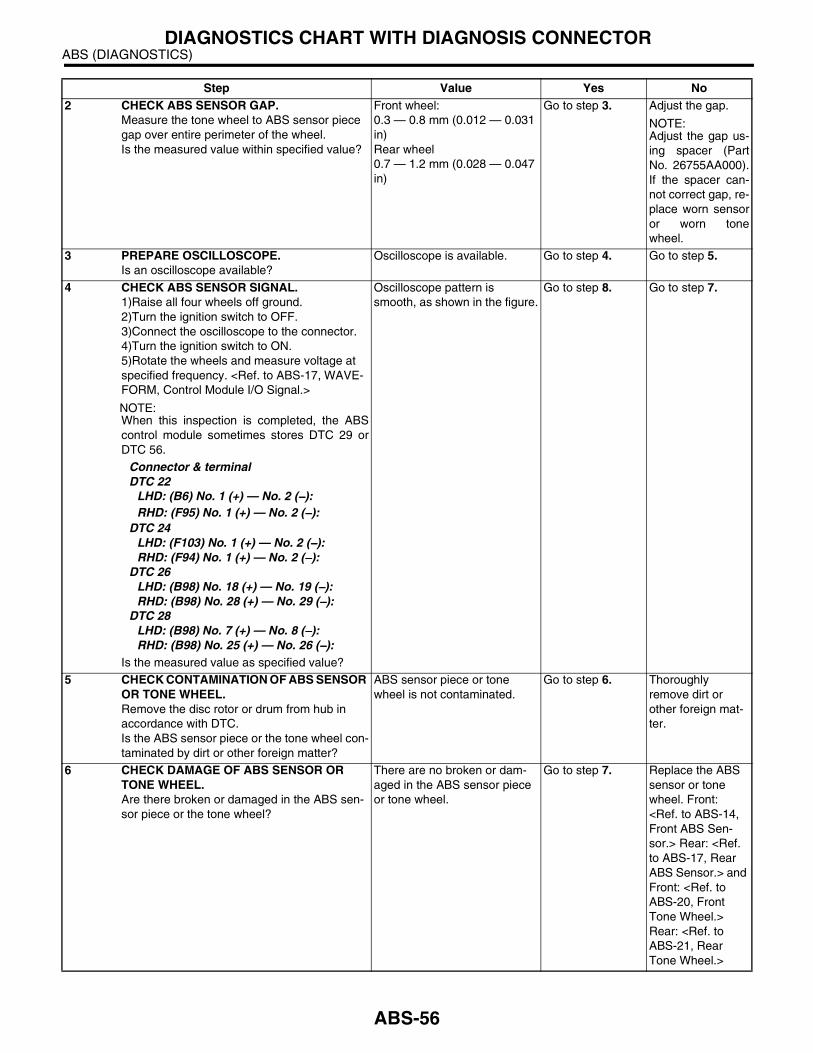
2 CHECK ABS SENSOR GAP.Measure the tone wheel to ABS sensor piece gap over entire perimeter of the wheel.Is the measured value within specified value?
Front wheel:0.3 — 0.8 mm (0.012 — 0.031 in)Rear wheel0.7 — 1.2 mm (0.028 — 0.047 in)
Go to step 3. Adjust the gap.
NOTE:Adjust the gap us-ing spacer (PartNo. 26755AA000).If the spacer can-not correct gap, re-place worn sensoror worn tonewheel.
3 PREPARE OSCILLOSCOPE.Is an oscilloscope available?
Oscilloscope is available. Go to step 4. Go to step 5.
4 CHECK ABS SENSOR SIGNAL.1)Raise all four wheels off ground.2)Turn the ignition switch to OFF.3)Connect the oscilloscope to the connector.4)Turn the ignition switch to ON.5)Rotate the wheels and measure voltage at specified frequency. <Ref. to ABS-17, WAVE-FORM, Control Module I/O Signal.>
NOTE:When this inspection is completed, the ABScontrol module sometimes stores DTC 29 orDTC 56.
Connector & terminalDTC 22
LHD: (B6) No. 1 (+) — No. 2 (−−−−):RHD: (F95) No. 1 (+) — No. 2 (−−−−):
DTC 24LHD: (F103) No. 1 (+) — No. 2 (−−−−):RHD: (F94) No. 1 (+) — No. 2 (−−−−):
DTC 26LHD: (B98) No. 18 (+) — No. 19 (−−−−):RHD: (B98) No. 28 (+) — No. 29 (−−−−):
DTC 28LHD: (B98) No. 7 (+) — No. 8 (−−−−):RHD: (B98) No. 25 (+) — No. 26 (−−−−):
Is the measured value as specified value?
Oscilloscope pattern is smooth, as shown in the figure.
Go to step 8. Go to step 7.
5 CHECK CONTAMINATION OF ABS SENSOR OR TONE WHEEL.Remove the disc rotor or drum from hub in accordance with DTC.Is the ABS sensor piece or the tone wheel con-taminated by dirt or other foreign matter?
ABS sensor piece or tone wheel is not contaminated.
Go to step 6. Thoroughly remove dirt or other foreign mat-ter.
6 CHECK DAMAGE OF ABS SENSOR OR TONE WHEEL.Are there broken or damaged in the ABS sen-sor piece or the tone wheel?
There are no broken or dam-aged in the ABS sensor piece or tone wheel.
Go to step 7. Replace the ABS sensor or tone wheel. Front: <Ref. to ABS-14, Front ABS Sen-sor.> Rear: <Ref. to ABS-17, Rear ABS Sensor.> and Front: <Ref. to ABS-20, Front Tone Wheel.> Rear: <Ref. to ABS-21, Rear Tone Wheel.>
Step Value Yes No
ABS-56

ABS (DIAGNOSTICS)DIAGNOSTICS CHART WITH DIAGNOSIS CONNECTOR
7 CHECK TONE WHEEL RUNOUT.Measure the tone wheel runout.Is the measured value less than specified value?
0.05 mm (0.0020 in) Go to step 8. Replace the tone wheel. Front: <Ref. to ABS-20, Front Tone Wheel.> Rear: <Ref. to ABS-21, Rear Tone Wheel.>
8 CHECK RESISTANCE OF ABS SENSOR.1)Turn the ignition switch to OFF.2)Disconnect the connector from ABS sensor.3)Measure the resistance between ABS sen-sor connector terminals while shaking the har-ness lightly.
TerminalFront RH No. 1 — No. 2:Front LH No. 1 — No. 2:Rear RH No. 1 — No. 2:Rear LH No. 1 — No. 2:
Is the measured value within specified value?
Front: 1 — 1.5 kΩRear: 1.025 — 1.265 kΩ
Go to step 9. Replace the ABS sensor. Front: <Ref. to ABS-14, Front ABS Sen-sor.> Rear: <Ref. to ABS-17, Rear ABS Sensor.>
9 CHECK GROUND SHORT OF ABS SENSOR.Measure the resistance between ABS sensor and chassis ground.
TerminalFront RH No. 1 — Chassis ground:Front LH No. 1 — Chassis ground:Rear RH No. 1 — Chassis ground:Rear LH No. 1 — Chassis ground:
Is the measured value more than specified value?
1 MΩ Go to step 10. Replace the ABS sensor. Front: <Ref. to ABS-14, Front ABS Sen-sor.> Rear: <Ref. to ABS-17, Rear ABS Sensor.>
10 CHECK HARNESS/CONNECTOR BETWEEN ABSCM&H/U AND ABS SENSOR.1)Connect the connector to ABS sensor.2)Disconnect the connector from ABSCM&H/U.3)Measure the resistance at ABSCM&H/U connector terminals.
Connector & terminalDTC 22
LHD: (B301) No. 11 — No. 12:RHD: (F49) No. 11 — No. 12:
DTC 24LHD: (B301) No. 9 — No. 10:RHD: (F49) No. 9 — No. 10:
DTC 26LHD: (B301) No. 14 — No. 15:RHD: (F49) No. 14 — No. 15:
DTC 28LHD: (B301) No. 7 — No. 8:RHD: (F49) No. 7 — No. 8:
Is the measured value within specified value?
Front: 1 — 1.5 kΩRear: 1.025 — 1.265 kΩ
Go to step 11. Repair the har-ness/connector between ABSCM&H/U and ABS sensor.
Step Value Yes No
ABS-57

ABS (DIAGNOSTICS)DIAGNOSTICS CHART WITH DIAGNOSIS CONNECTOR
11 CHECK GROUND SHORT OF HARNESS.Measure the resistance between ABSCM&H/U connector and chassis ground.
Connector & terminalDTC 22
LHD: (B301) No. 11 — Chassis ground:RHD: (F49) No. 11 — Chassis ground:
DTC 24LHD: (B301) No. 9 — Chassis ground:RHD: (F49) No. 9 — Chassis ground:
DTC 26LHD: (B301) No. 14 — Chassis ground:RHD: (F49) No. 14 — Chassis ground:
DTC 28LHD: (B301) No. 7 — Chassis ground:RHD: (F49) No. 7 — Chassis ground:
Is the measured value more than specified value?
1 MΩ Go to step 12. Repair the har-ness/connector between ABSCM&H/U and ABS sensor.
12 CHECK GROUND CIRCUIT OF ABSCM&H/U.Measure the resistance between ABSCM&H/U and chassis ground.
Connector & terminal(B301) No. 23 — Chassis ground:
Is the measured value less than specified value?
0.5 Ω Go to step 13. Repair the ABSCM&H/U ground harness.
13 CHECK POOR CONTACT IN CONNECTORS.Is there poor contact in connectors between ABSCM&H/U and ABS sensor?
There is no poor contact. Go to step 14. Repair the con-nector.
14 CHECK SOURCES OF SIGNAL NOISE.Is the car telephone or wireless transmitter properly installed?
Correctly installed. Go to step 15. Properly install the car telephone or wireless transmit-ter.
15 CHECK SOURCES OF SIGNAL NOISE.Are noise sources (such as an antenna) installed near the sensor harness?
Not installed. Go to step 16. Install the noise sources apart from sensor harness.
16 CHECK SHIELD CIRCUIT.1)Disconnect the connectors (B303) and (F62).2)Measure the resistance between shield con-nector and chassis ground.
Connector & terminalDTC 22
LHD: (F103) No. 4 — Chassis ground:RHD: (F48) No. 2 — Chassis ground:
DTC 24LHD: (F103) No. 5 — Chassis ground:RHD: (F48) No. 1 — Chassis ground:
DTC 26LHD: (F103) No. 3 — Chassis ground:RHD: (F48) No. 3 — Chassis ground:
DTC 28LHD: (F103) No. 3 — Chassis ground:RHD: (F48) No. 3 — Chassis ground:
Is the measured value less than specified value?
0.5 Ω Go to step 17. Repair the shield harness.
Step Value Yes No
ABS-58

ABS (DIAGNOSTICS)DIAGNOSTICS CHART WITH DIAGNOSIS CONNECTOR
17 CHECK ABSCM&H/U.1)Connect all connectors.2)Erase the memory.3)Perform the inspection mode.4)Read out the DTC.Is the same DTC as in current diagnosis still being output?
Same DTC is not output. Go to step 18. Replace the ABSCM&H/U. <Ref. to ABS-7, ABS Control Mod-ule and Hydraulic Control Unit (ABSCM&H/U).>
18 CHECK ANY OTHER DIAGNOSTIC TROU-BLE CODES (DTCs) APPEARANCE.Are other DTCs being output?
Other DTC is not output. A temporary noise interference.
NOTE:Although the ABSwarning light re-mains illuminatingat this point, this isa normal condition.Vehicle must bedriven at approx.12 km/h (7.46MPH) or faster toturn off ABS warn-ing light. Makesure that the ABSwarning light goesoff after driving ve-hicle.
Proceed with the diagnosis corre-sponding to DTC.
Step Value Yes No
ABS-59

ABS (DIAGNOSTICS)DIAGNOSTICS CHART WITH DIAGNOSIS CONNECTOR
M: DTC 29 — ABNORMAL ABS SENSOR (ABNORMAL ABS SENSOR SIGNAL) (ANY ONE OF FOUR) —
DIAGNOSIS:• Faulty ABS sensor signal (noise, irregular signal, etc.)• Faulty tone wheel• Wheels turning freely for a long timeTROUBLE SYMPTOM:• ABS does not operate.• EBD does not operate.
NOTE:In addition to the ABS warning light, brake warning light illuminates.
ABS-60
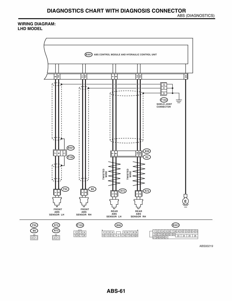
ABS (DIAGNOSTICS)DIAGNOSTICS CHART WITH DIAGNOSIS CONNECTOR
WIRING DIAGRAM:LHD MODEL
ABS00219
ABS CONTROL MODULE AND HYDRAULIC CONTROL UNIT
SHIELD JOINTCONNECTOR
B301
15
14
109 87 23
F103
REAR ABSSENSOR RH
B98
R72
R2
E
17 6
3
54
19
1887
REAR ABSSENSOR LH
R73
FRONT ABSSENSOR RH
B6
21
21
TW
IST
ED
WIR
E
TW
IST
ED
WIR
E
21
FRONT ABSSENSOR LH
F94
B321
F103
F103 B98
B6
F94 R72
R73
21
2 1
B301
1 2 3 4 5 6 7 8 9 10 11 12 13 14 1516 17 18 19 20 21 22
27 28 29 30 3123 24 25 26
12
11
1 2 3 4 5 6 7 8 910 11 12 13 14 15 16 17 18 19 20
1 2 3 45 6 7 8
2 1
ABS-61

ABS (DIAGNOSTICS)DIAGNOSTICS CHART WITH DIAGNOSIS CONNECTOR
RHD MODEL
ABS00224
ABS CONTROL MODULE AND HYDRAULIC CONTROL UNIT
SHIELD JOINTCONNECTOR
F49
15
14
109 87 23
F48
REAR ABSSENSOR RH
B98
R72
R2
E
12
29
28
26
25
REAR ABSSENSOR LH
R73
FRONT ABSSENSOR RH
F95
21
21
TW
IST
ED
WIR
E
TW
IST
ED
WIR
E
21
FRONT ABSSENSOR LH
F94
F62 B98F95F94 R72 R73
21
2 1
F49
1 2 3 4 5 6 7 8 9 10 11 12 13 14 1516 17 18 19 20 21 22
27 28 29 30 3123 24 25 26
12
11
1 2 3 4 5 6 7 8 910 11 12 13 14 15 16 17 18 19 20
1 2 3 45 6 7 8
2 1
10 11 12 13 14 15 16 17 181 2 3 4 7 85 69
F45
F45
B62
18
1787 15
38
ABS-62

ABS (DIAGNOSTICS)DIAGNOSTICS CHART WITH DIAGNOSIS CONNECTOR
Step Value Yes No1 CHECK IF THE WHEELS HAVE TURNED
FREELY FOR A LONG TIME.Check if the wheels have been turned freely for more than 1 minute, such as when vehicle is jacked-up, under full-lock cornering or when tire is not in contact with road surface.
Wheels have not been turned freely.
Go to step 2. The ABS is nor-mal. Erase the DTC.
NOTE:When the wheelsturn freely for along time, such aswhen the vehicle istowed or jacked-up, or when steer-ing wheel is contin-uously turned allthe way, this DTCmay sometimesoccur.
2 CHECK TIRE SPECIFICATIONS.Turn the ignition switch to OFF.Are the tire specifications correct?
Tire specifications are correct. Go to step 3. Replace the tire.
3 CHECK WEAR OF TIRE.Is the tire worn excessively?
Tire is not worn excessively. Go to step 4. Replace tire.
4 CHECK TIRE PRESSURE.Is the tire pressure correct?
Tire pressure is correct. Go to step 5. Adjust tire pres-sure.
5 CHECK INSTALLATION OF ABS SENSOR.Are the ABS sensor installation bolts tightened securely?
33 N·m (3.4 kgf-m, 24.6 ft-lb) Go to step 6. Tighten the ABS sensor installation bolts securely.
6 CHECK ABS SENSOR GAP.Measure the tone wheel to ABS sensor piece gap over entire perimeter of the wheel.Is the measured value within specified value?
Front wheel:0.3 — 0.8 mm (0.012 — 0.031 in)Rear wheel0.7 — 1.2 mm (0.028 — 0.047 in)
Go to step 7. Adjust the gap.
NOTE:Adjust the gap us-ing spacer (PartNo. 26755AA000).If the spacer can-not correct gap, re-place worn sensoror worn tonewheel.
7 PREPARE OSCILLOSCOPE.Is an oscilloscope available?
Oscilloscope is available. Go to step 8. Go to step 9.
ABS-63
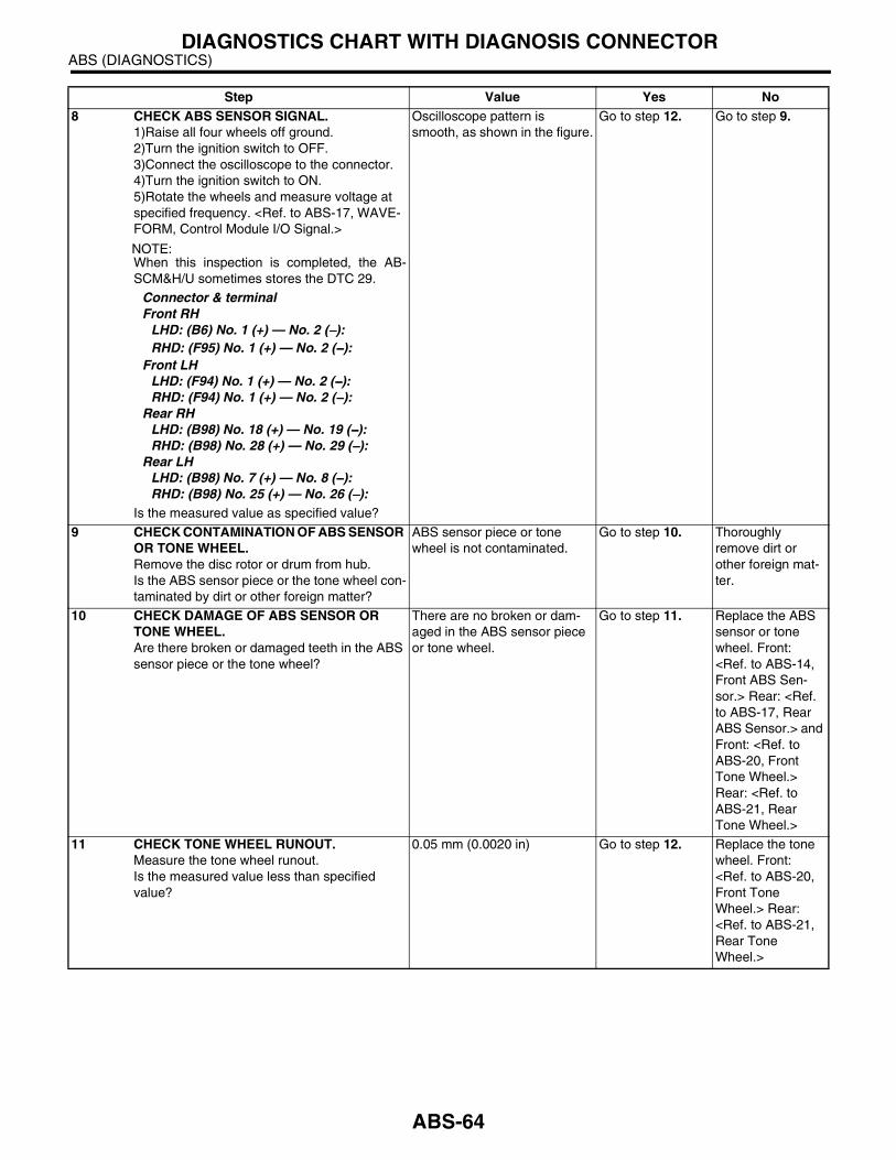
ABS (DIAGNOSTICS)DIAGNOSTICS CHART WITH DIAGNOSIS CONNECTOR
8 CHECK ABS SENSOR SIGNAL.1)Raise all four wheels off ground.2)Turn the ignition switch to OFF.3)Connect the oscilloscope to the connector.4)Turn the ignition switch to ON.5)Rotate the wheels and measure voltage at specified frequency. <Ref. to ABS-17, WAVE-FORM, Control Module I/O Signal.>
NOTE:When this inspection is completed, the AB-SCM&H/U sometimes stores the DTC 29.
Connector & terminalFront RH
LHD: (B6) No. 1 (+) — No. 2 (−−−−):RHD: (F95) No. 1 (+) — No. 2 (−−−−):
Front LHLHD: (F94) No. 1 (+) — No. 2 (−−−−):RHD: (F94) No. 1 (+) — No. 2 (−−−−):
Rear RHLHD: (B98) No. 18 (+) — No. 19 (−−−−):RHD: (B98) No. 28 (+) — No. 29 (−−−−):
Rear LHLHD: (B98) No. 7 (+) — No. 8 (−−−−):RHD: (B98) No. 25 (+) — No. 26 (−−−−):
Is the measured value as specified value?
Oscilloscope pattern is smooth, as shown in the figure.
Go to step 12. Go to step 9.
9 CHECK CONTAMINATION OF ABS SENSOR OR TONE WHEEL.Remove the disc rotor or drum from hub.Is the ABS sensor piece or the tone wheel con-taminated by dirt or other foreign matter?
ABS sensor piece or tone wheel is not contaminated.
Go to step 10. Thoroughly remove dirt or other foreign mat-ter.
10 CHECK DAMAGE OF ABS SENSOR OR TONE WHEEL.Are there broken or damaged teeth in the ABS sensor piece or the tone wheel?
There are no broken or dam-aged in the ABS sensor piece or tone wheel.
Go to step 11. Replace the ABS sensor or tone wheel. Front: <Ref. to ABS-14, Front ABS Sen-sor.> Rear: <Ref. to ABS-17, Rear ABS Sensor.> and Front: <Ref. to ABS-20, Front Tone Wheel.> Rear: <Ref. to ABS-21, Rear Tone Wheel.>
11 CHECK TONE WHEEL RUNOUT.Measure the tone wheel runout.Is the measured value less than specified value?
0.05 mm (0.0020 in) Go to step 12. Replace the tone wheel. Front: <Ref. to ABS-20, Front Tone Wheel.> Rear: <Ref. to ABS-21, Rear Tone Wheel.>
Step Value Yes No
ABS-64

ABS (DIAGNOSTICS)DIAGNOSTICS CHART WITH DIAGNOSIS CONNECTOR
12 CHECK ABSCM&H/U.1)Turn the ignition switch to OFF.2)Connect all connectors.3)Erase the memory.4)Perform the inspection mode.5)Read out the DTC.Is the same DTC as in current diagnosis still being output?
Same DTC is not output. Go to step 13. Replace the ABSCM&H/U. <Ref. to ABS-7, ABS Control Mod-ule and Hydraulic Control Unit (ABSCM&H/U).>
13 CHECK ANY OTHER DIAGNOSTIC TROU-BLE CODES (DTCs) APPEARANCE.Are other DTCs being output?
Other DTC is not output. A temporary poor contact.
Proceed with the diagnosis corre-sponding to DTC.
Step Value Yes No
ABS-65

ABS (DIAGNOSTICS)DIAGNOSTICS CHART WITH DIAGNOSIS CONNECTOR
N: DTC 31 — ABNORMAL INLET SOLENOID VALVE CIRCUIT(S) IN ABSCM&H/U (FRONT RH) —
NOTE:For the diagnostic procedure, refer to DTC 37. <Ref. to ABS-67, DTC 37 — ABNORMAL INLET SOLENOIDVALVE CIRCUIT(S) IN ABSCM&H/U (REAR LH) —, Diagnostics Chart with Diagnosis Connector.>
O: DTC 33 — ABNORMAL INLET SOLENOID VALVE CIRCUIT(S) IN ABSCM&H/U (FRONT LH) —
NOTE:For the diagnostic procedure, refer to DTC 37. <Ref. to ABS-67, DTC 37 — ABNORMAL INLET SOLENOIDVALVE CIRCUIT(S) IN ABSCM&H/U (REAR LH) —, Diagnostics Chart with Diagnosis Connector.>
P: DTC 35 — ABNORMAL INLET SOLENOID VALVE CIRCUIT(S) IN ABSCM&H/U (REAR RH) —
NOTE:For the diagnostic procedure, refer to DTC 37. <Ref. to ABS-67, DTC 37 — ABNORMAL INLET SOLENOIDVALVE CIRCUIT(S) IN ABSCM&H/U (REAR LH) —, Diagnostics Chart with Diagnosis Connector.>
ABS-66

ABS (DIAGNOSTICS)DIAGNOSTICS CHART WITH DIAGNOSIS CONNECTOR
Q: DTC 37 — ABNORMAL INLET SOLENOID VALVE CIRCUIT(S) IN ABSCM&H/U (REAR LH) —
DIAGNOSIS:• Faulty harness/connector• Faulty inlet solenoid valve in ABSCM&H/UTROUBLE SYMPTOM:• ABS does not operate.• EBD does not operate.
NOTE:In addition to the ABS warning light, brake warning light illuminates.
ABS-67

ABS (DIAGNOSTICS)DIAGNOSTICS CHART WITH DIAGNOSIS CONNECTOR
WIRING DIAGRAM:
ABS00229
ABS CONTROL MODULE AND HYDRAULIC CONTROL UNIT
1 2 3 4 5 6 7 8 9 10 11 12 13 14 1516 17 18 19 20 21 22
27 28 29 30 3123 24 25 26
BATTERY
SB
F-1
SB
F-4
No
.18
GENERATOR
E
E
231
IGNITIONSWITCH
B301
: LHD MODEL
: RHD MODEL
LHD
RHD
F49
LHD
RHD
:
:
B301
F49
LHD
RHD
:
:
ABS-68

ABS (DIAGNOSTICS)DIAGNOSTICS CHART WITH DIAGNOSIS CONNECTOR
Step Value Yes No1 CHECK INPUT VOLTAGE OF ABSCM&H/U.
1)Turn the ignition switch to OFF.2)Disconnect the connector from ABSCM&H/U.3)Run the engine at idle.4)Measure the voltage between ABSCM&H/U connector and chassis ground.
Connector & terminal(B301) No. 1 (+) — Chassis ground (−−−−):
Is the measured value within specified value?
10 — 15 V Go to step 2. Repair the har-ness connector between ABS relay and ABSCM&H/U.
2 CHECK GROUND CIRCUIT OF ABSCM&H/U.1)Turn the ignition switch to OFF.2)Measure the resistance between ABSCM&H/U connector and chassis ground.
Connector & terminalLHD: (B301) No. 23 — Chassis ground:RHD: (F49) No. 23 — Chassis ground:
Is the measured value less than specified value?
0.5 Ω Go to step 3. Repair the ABSCM&H/U ground harness.
3 CHECK POOR CONTACT IN CONNECTORS.Is there poor contact in connectors between generator, battery and ABSCM&H/U?
There is no poor contact. Go to step 4. Repair the con-nector.
4 CHECK ABSCM&H/U.1)Connect all connectors.2)Erase the memory.3)Perform the inspection mode.4)Read out the DTC.Is the same DTC as in the current diagnosis still being output?
Same DTC is not output. Go to step 5. Replace the ABSCM&H/U. <Ref. to ABS-7, ABS Control Mod-ule and Hydraulic Control Unit (ABSCM&H/U).>
5 CHECK ANY OTHER DIAGNOSTIC TROU-BLE CODES (DTCs) APPEARANCE.Are other DTCs being output?
Other DTC is not output. A temporary poor contact.
Proceed with the diagnosis corre-sponding to DTC.
ABS-69

ABS (DIAGNOSTICS)DIAGNOSTICS CHART WITH DIAGNOSIS CONNECTOR
R: DTC 32 — ABNORMAL OUTLET SOLENOID VALVE CIRCUIT(S) IN ABSCM&H/U (FRONT RH) —
NOTE:For the diagnostic procedure, refer to DTC 38. <Ref. to ABS-71, DTC 38 — ABNORMAL OUTLET SOLE-NOID VALVE CIRCUIT(S) IN ABSCM&H/U (REAR LH) —, Diagnostics Chart with Diagnosis Connector.>
S: DTC 34 — ABNORMAL OUTLET SOLENOID VALVE CIRCUIT(S) IN ABSCM&H/U (FRONT LH) —
NOTE:For the diagnostic procedure, refer to DTC 38. <Ref. to ABS-71, DTC 38 — ABNORMAL OUTLET SOLE-NOID VALVE CIRCUIT(S) IN ABSCM&H/U (REAR LH) —, Diagnostics Chart with Diagnosis Connector.>
T: DTC 36 — ABNORMAL OUTLET SOLENOID VALVE CIRCUIT(S) IN ABSCM&H/U (REAR RH) —
NOTE:For the diagnostic procedure, refer to DTC 38. <Ref. to ABS-71, DTC 38 — ABNORMAL OUTLET SOLE-NOID VALVE CIRCUIT(S) IN ABSCM&H/U (REAR LH) —, Diagnostics Chart with Diagnosis Connector.>
ABS-70
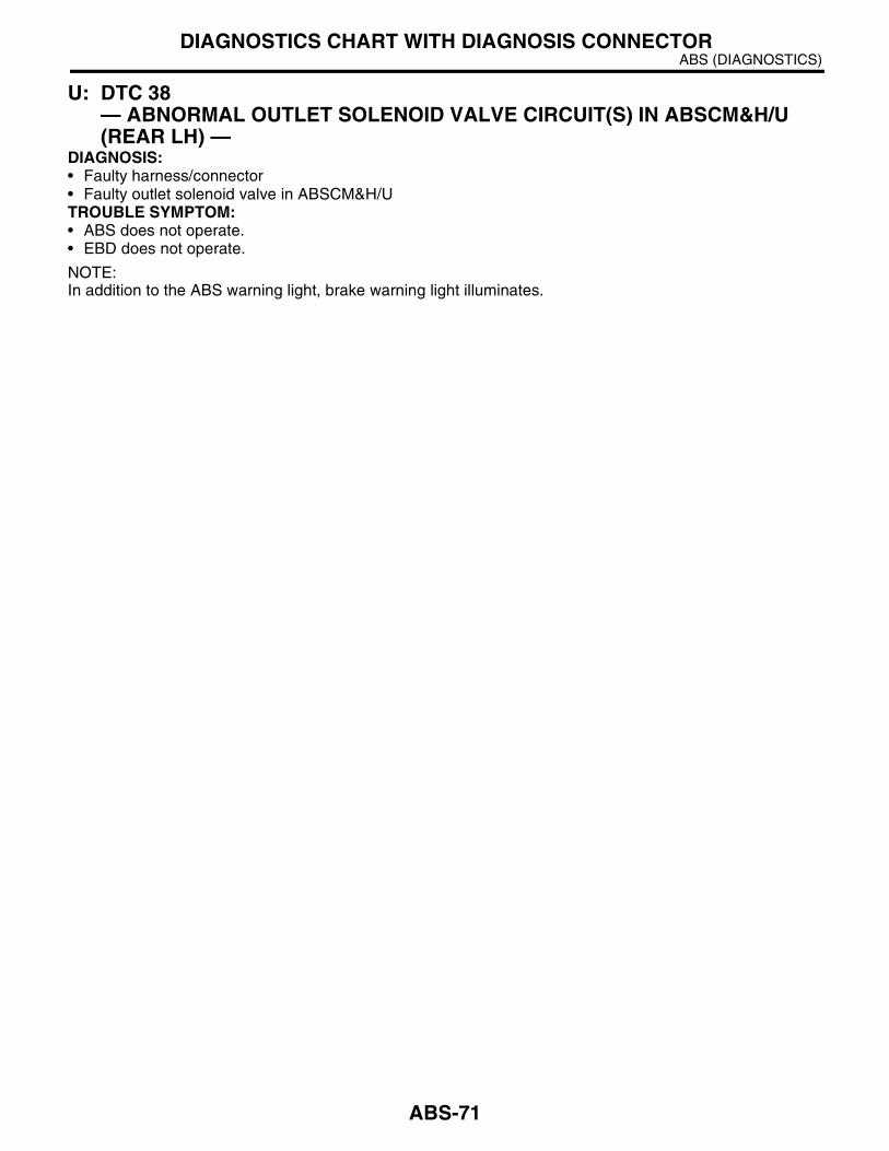
ABS (DIAGNOSTICS)DIAGNOSTICS CHART WITH DIAGNOSIS CONNECTOR
U: DTC 38 — ABNORMAL OUTLET SOLENOID VALVE CIRCUIT(S) IN ABSCM&H/U (REAR LH) —
DIAGNOSIS:• Faulty harness/connector• Faulty outlet solenoid valve in ABSCM&H/UTROUBLE SYMPTOM:• ABS does not operate.• EBD does not operate.
NOTE:In addition to the ABS warning light, brake warning light illuminates.
ABS-71

ABS (DIAGNOSTICS)DIAGNOSTICS CHART WITH DIAGNOSIS CONNECTOR
WIRING DIAGRAM:
ABS00229
ABS CONTROL MODULE AND HYDRAULIC CONTROL UNIT
1 2 3 4 5 6 7 8 9 10 11 12 13 14 1516 17 18 19 20 21 22
27 28 29 30 3123 24 25 26
BATTERY
SB
F-1
SB
F-4
No
.18
GENERATOR
E
E
231
IGNITIONSWITCH
B301
: LHD MODEL
: RHD MODEL
LHD
RHD
F49
LHD
RHD
:
:
B301
F49
LHD
RHD
:
:
ABS-72
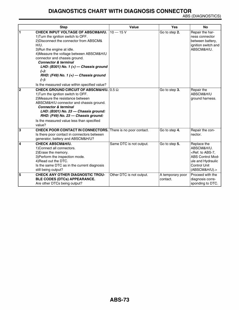
ABS (DIAGNOSTICS)DIAGNOSTICS CHART WITH DIAGNOSIS CONNECTOR
Step Value Yes No1 CHECK INPUT VOLTAGE OF ABSCM&H/U.
1)Turn the ignition switch to OFF.2)Disconnect the connector from ABSCM&H/U.3)Run the engine at idle.4)Measure the voltage between ABSCM&H/U connector and chassis ground.
Connector & terminalLHD: (B301) No. 1 (+) — Chassis ground (−−−−):RHD: (F49) No. 1 (+) — Chassis ground (−−−−):
Is the measured value within specified value?
10 — 15 V Go to step 2. Repair the har-ness connector between battery, ignition switch and ABSCM&H/U.
2 CHECK GROUND CIRCUIT OF ABSCM&H/U.1)Turn the ignition switch to OFF.2)Measure the resistance between ABSCM&H/U connector and chassis ground.
Connector & terminalLHD: (B301) No. 23 — Chassis ground:RHD: (F49) No. 23 — Chassis ground:
Is the measured value less than specified value?
0.5 Ω Go to step 3. Repair the ABSCM&H/U ground harness.
3 CHECK POOR CONTACT IN CONNECTORS.Is there poor contact in connectors between generator, battery and ABSCM&H/U?
There is no poor contact. Go to step 4. Repair the con-nector.
4 CHECK ABSCM&H/U.1)Connect all connectors.2)Erase the memory.3)Perform the inspection mode.4)Read out the DTC.Is the same DTC as in the current diagnosis still being output?
Same DTC is not output. Go to step 5. Replace the ABSCM&H/U. <Ref. to ABS-7, ABS Control Mod-ule and Hydraulic Control Unit (ABSCM&H/U).>
5 CHECK ANY OTHER DIAGNOSTIC TROU-BLE CODES (DTCs) APPEARANCE.Are other DTCs being output?
Other DTC is not output. A temporary poor contact.
Proceed with the diagnosis corre-sponding to DTC.
ABS-73

ABS (DIAGNOSTICS)DIAGNOSTICS CHART WITH DIAGNOSIS CONNECTOR
V: DTC 41 — ABNORMAL ABS CONTROL MODULE —
DIAGNOSIS:• Faulty ABSCM&H/U.TROUBLE SYMPTOM:• ABS does not operate.• EBD does not operate.
NOTE:In addition to the ABS warning light, brake warning light illuminates.WIRING DIAGRAM:
ABS00234
E
ABS CONTROL MODULE ANDHYDRAULIC CONTROL UNIT
23
1 2 3 4 5 6 7 8 9 10 11 12 13 14 1516 17 18 19 20 21 22
27 28 29 30 3123 24 25 26
: LHD MODEL
: RHD MODEL
LHD
RHD
B301
F49
LHD
RHD
:
:
B301
F49
LHD
RHD
:
:
ABS-74

ABS (DIAGNOSTICS)DIAGNOSTICS CHART WITH DIAGNOSIS CONNECTOR
Step Value Yes No1 CHECK GROUND CIRCUIT OF ABSCM&H/U.
1)Turn the ignition switch to OFF.2)Disconnect the connector from ABSCM&H/U.3)Measure the resistance between ABSCM&H/U and chassis ground.
Connector & terminalLHD: (B301) No. 23 — Chassis ground:RHD: (F49) No. 23 — Chassis ground:
Is the measured value less than specified value?
0.5 Ω Go to step 2. Repair the ABSCM&H/U ground harness.
2 CHECK POOR CONTACT IN CONNECTORS.Is there poor contact in connectors between battery, ignition switch and ABSCM&H/U?
There is no poor contact. Go to step 3. Repair the con-nector.
3 CHECK SOURCES OF SIGNAL NOISE.Is the car telephone or the wireless transmitter properly installed?
Correctly installed. Go to step 4. Properly install the car telephone or wireless transmit-ter.
4 CHECK SOURCES OF SIGNAL NOISE.Are noise sources (such as an antenna) installed near the sensor harness?
Not installed. Go to step 5. Install the noise sources apart from the sensor har-ness.
5 CHECK ABSCM&H/U.1)Connect all connectors.2)Erase the memory.3)Perform the inspection mode.4)Read out the DTC.Is the same DTC as in current diagnosis still being output?
Same DTC is not output. Go to step 6. Replace the ABSCM&H/U. <Ref. to ABS-7, ABS Control Mod-ule and Hydraulic Control Unit (ABSCM&H/U).>
6 CHECK ANY OTHER DIAGNOSTIC TROU-BLE CODES (DTCs) APPEARANCE.Are other DTCs being output?
Other DTC is not output. A temporary poor contact.
Proceed with the diagnosis corre-sponding to DTC.
ABS-75

ABS (DIAGNOSTICS)DIAGNOSTICS CHART WITH DIAGNOSIS CONNECTOR
W: DTC 42 — SOURCE VOLTAGE IS ABNORMAL. —
DIAGNOSIS:• Power source voltage of the ABSCM&H/U is low or high.TROUBLE SYMPTOM:• ABS does not operate.• EBD does not operate.
NOTE:In addition to the ABS warning light, brake warning light illuminates temporarily. Both warning lights go off onthe recovery of voltage.
ABS-76
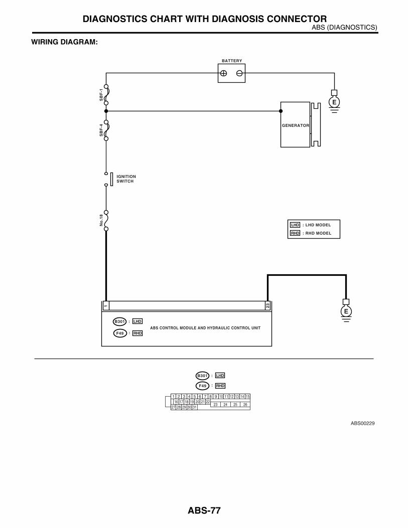
ABS (DIAGNOSTICS)DIAGNOSTICS CHART WITH DIAGNOSIS CONNECTOR
WIRING DIAGRAM:
ABS00229
ABS CONTROL MODULE AND HYDRAULIC CONTROL UNIT
1 2 3 4 5 6 7 8 9 10 11 12 13 14 1516 17 18 19 20 21 22
27 28 29 30 3123 24 25 26
BATTERY
SB
F-1
SB
F-4
No
.18
GENERATOR
E
E
231
IGNITIONSWITCH
B301
: LHD MODEL
: RHD MODEL
LHD
RHD
F49
LHD
RHD
:
:
B301
F49
LHD
RHD
:
:
ABS-77

ABS (DIAGNOSTICS)DIAGNOSTICS CHART WITH DIAGNOSIS CONNECTOR
Step Value Yes No1 CHECK GENERATOR.
1)Start the engine.2)Idle after warm-up.3)Measure the voltage between generator B terminal and chassis ground.
TerminalGenerator B terminal (+) — Chassis ground (−−−−):
Is the measured value within specified value?
10 — 17 V Go to step 2. Repair the genera-tor. <Ref. to SC(SOHC)-15, Generator.>
2 CHECK BATTERY TERMINAL.Turn the ignition switch to OFF.Are the positive and negative battery terminals tightly clamped?
Tightly clamped. Go to step 3. Tighten the clamp of terminal.
3 CHECK INPUT VOLTAGE OF ABSCM&H/U.1)Disconnect the connector from ABSCM&H/U.2)Run the engine at idle.3)Operate the electric load applying devices, such as the headlight, A/C, and defogger.4)Measure the voltage between ABSCM&H/U connector and chassis ground.
Connector & terminalLHD: (B301) No. 1 (+) — Chassis ground (−−−−):RHD: (F49) No. 1 (+) — Chassis ground (−−−−):
Is the measured value within specified value?
10 — 17 V Go to step 4. Repair the har-ness connector between battery, ignition switch and ABSCM&H/U.
4 CHECK GROUND CIRCUIT OF ABSCM&H/U.1)Turn the ignition switch to OFF.2)Measure the resistance between ABSCM&H/U connector and chassis ground.
Connector & terminalLHD: (B301) No. 23 — Chassis ground:RHD: (F49) No. 23 — Chassis ground:
Is the measured value less than specified value?
0.5 Ω Go to step 5. Repair the ABSCM&H/U ground harness.
5 CHECK POOR CONTACT IN CONNECTORS.Is there poor contact in connectors between generator, battery and ABSCM&H/U?
There is no poor contact. Go to step 6. Repair the con-nector.
6 CHECK ABSCM&H/U.1)Connect all connectors.2)Erase the memory.3)Perform the inspection mode.4)Read out the DTC.Is the same DTC as in current diagnosis still being output?
Same DTC is not output. Go to step 7. Replace the ABSCM&H/U. <Ref. to ABS-7, ABS Control Mod-ule and Hydraulic Control Unit (ABSCM&H/U).>
7 CHECK ANY OTHER DIAGNOSTIC TROU-BLE CODES (DTCs) APPEARANCE.Are other DTCs being output?
Other DTC is not output. A temporary poor contact.
Proceed with the diagnosis corre-sponding to DTC.
ABS-78

ABS (DIAGNOSTICS)DIAGNOSTICS CHART WITH DIAGNOSIS CONNECTOR
X: DTC 44 — A COMBINATION OF AT CONTROL ABNORMAL —
DIAGNOSIS:• Combination of AT control faultsTROUBLE SYMPTOM:• ABS does not operate.WIRING DIAGRAM:
ABS00239
B55
1 2 3 4 5 6 7 8 9 10 11 12 13 14 1516 17 18 19 20 21 22
27 28 29 30 3123 24 25 26
ABS CONTROL MODULE ANDHYDRAULIC CONTROL UNIT
313
TCMB55
21
1 2 3 410 11 1219 20 21
135 614 15
7 8 916 17 1822 23 24
B301
F49
LHD
RHD
:
:
: LHD MODEL
: RHD MODEL
LHD
RHD
B301
F49
LHD
RHD
:
:
ABS-79
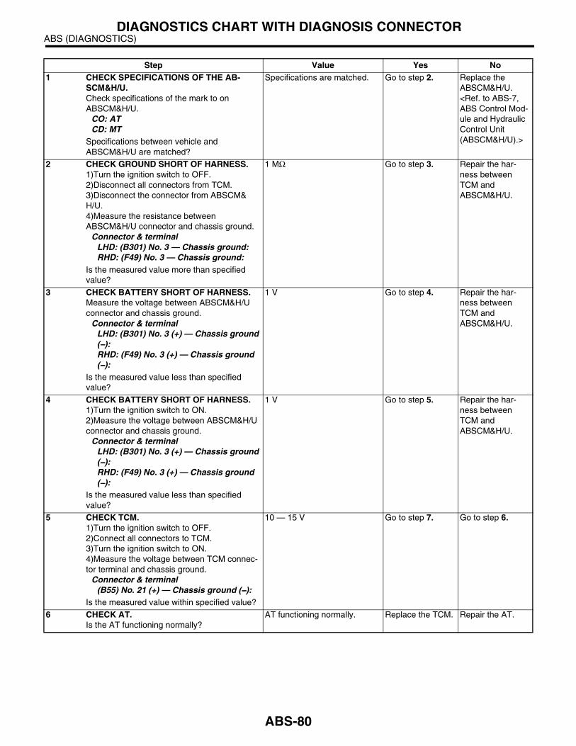
ABS (DIAGNOSTICS)DIAGNOSTICS CHART WITH DIAGNOSIS CONNECTOR
Step Value Yes No1 CHECK SPECIFICATIONS OF THE AB-
SCM&H/U.Check specifications of the mark to on ABSCM&H/U.
CO: AT CD: MT
Specifications between vehicle and ABSCM&H/U are matched?
Specifications are matched. Go to step 2. Replace the ABSCM&H/U. <Ref. to ABS-7, ABS Control Mod-ule and Hydraulic Control Unit (ABSCM&H/U).>
2 CHECK GROUND SHORT OF HARNESS.1)Turn the ignition switch to OFF.2)Disconnect all connectors from TCM.3)Disconnect the connector from ABSCM&H/U.4)Measure the resistance between ABSCM&H/U connector and chassis ground.
Connector & terminalLHD: (B301) No. 3 — Chassis ground:RHD: (F49) No. 3 — Chassis ground:
Is the measured value more than specified value?
1 MΩ Go to step 3. Repair the har-ness between TCM and ABSCM&H/U.
3 CHECK BATTERY SHORT OF HARNESS.Measure the voltage between ABSCM&H/U connector and chassis ground.
Connector & terminalLHD: (B301) No. 3 (+) — Chassis ground (−−−−):RHD: (F49) No. 3 (+) — Chassis ground (−−−−):
Is the measured value less than specified value?
1 V Go to step 4. Repair the har-ness between TCM and ABSCM&H/U.
4 CHECK BATTERY SHORT OF HARNESS.1)Turn the ignition switch to ON.2)Measure the voltage between ABSCM&H/U connector and chassis ground.
Connector & terminalLHD: (B301) No. 3 (+) — Chassis ground (−−−−):RHD: (F49) No. 3 (+) — Chassis ground (−−−−):
Is the measured value less than specified value?
1 V Go to step 5. Repair the har-ness between TCM and ABSCM&H/U.
5 CHECK TCM.1)Turn the ignition switch to OFF.2)Connect all connectors to TCM.3)Turn the ignition switch to ON.4)Measure the voltage between TCM connec-tor terminal and chassis ground.
Connector & terminal(B55) No. 21 (+) — Chassis ground (−−−−):
Is the measured value within specified value?
10 — 15 V Go to step 7. Go to step 6.
6 CHECK AT.Is the AT functioning normally?
AT functioning normally. Replace the TCM. Repair the AT.
ABS-80
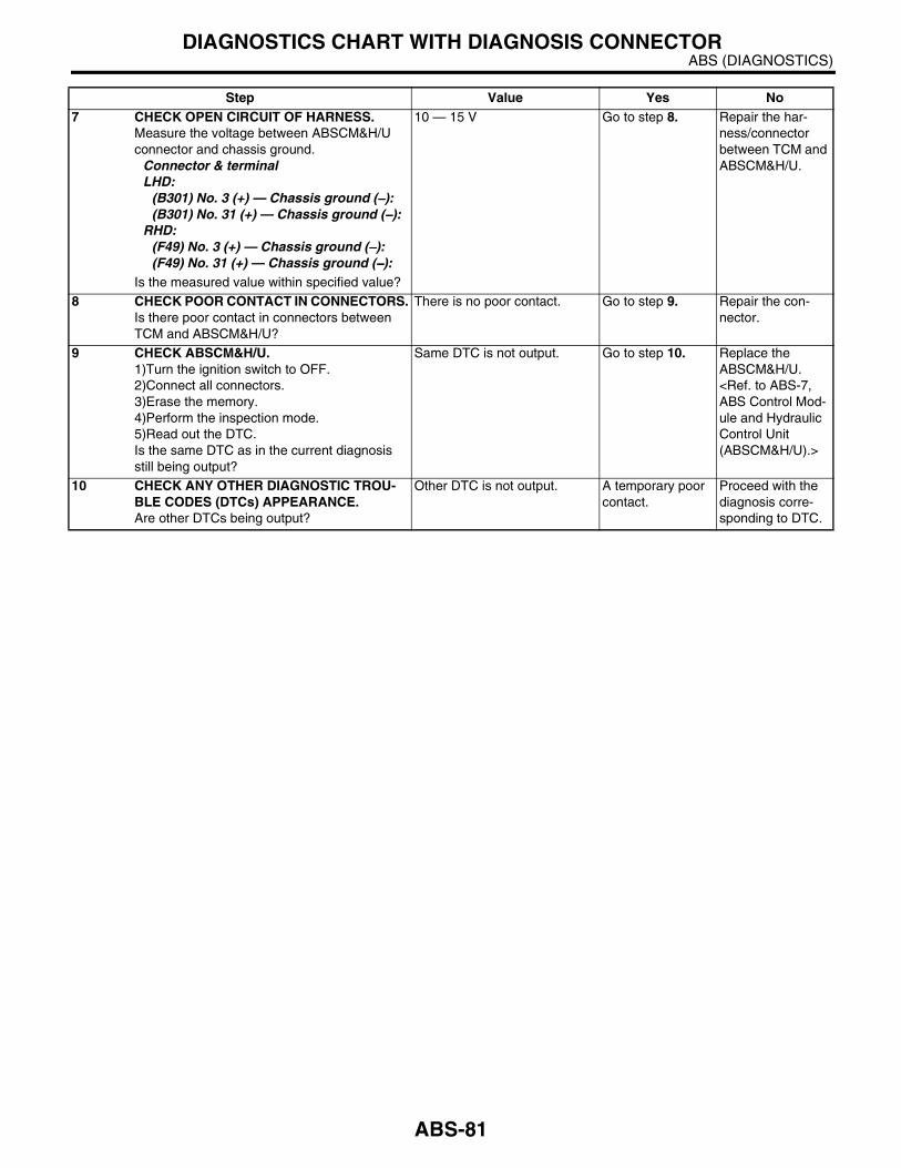
ABS (DIAGNOSTICS)DIAGNOSTICS CHART WITH DIAGNOSIS CONNECTOR
7 CHECK OPEN CIRCUIT OF HARNESS.Measure the voltage between ABSCM&H/U connector and chassis ground.
Connector & terminalLHD:
(B301) No. 3 (+) — Chassis ground (−−−−):(B301) No. 31 (+) — Chassis ground (−−−−):
RHD:(F49) No. 3 (+) — Chassis ground (−−−−):(F49) No. 31 (+) — Chassis ground (−−−−):
Is the measured value within specified value?
10 — 15 V Go to step 8. Repair the har-ness/connector between TCM and ABSCM&H/U.
8 CHECK POOR CONTACT IN CONNECTORS.Is there poor contact in connectors between TCM and ABSCM&H/U?
There is no poor contact. Go to step 9. Repair the con-nector.
9 CHECK ABSCM&H/U.1)Turn the ignition switch to OFF.2)Connect all connectors.3)Erase the memory.4)Perform the inspection mode.5)Read out the DTC.Is the same DTC as in the current diagnosis still being output?
Same DTC is not output. Go to step 10. Replace the ABSCM&H/U. <Ref. to ABS-7, ABS Control Mod-ule and Hydraulic Control Unit (ABSCM&H/U).>
10 CHECK ANY OTHER DIAGNOSTIC TROU-BLE CODES (DTCs) APPEARANCE.Are other DTCs being output?
Other DTC is not output. A temporary poor contact.
Proceed with the diagnosis corre-sponding to DTC.
Step Value Yes No
ABS-81

ABS (DIAGNOSTICS)DIAGNOSTICS CHART WITH DIAGNOSIS CONNECTOR
Y: DTC 51 — ABNORMAL VALVE RELAY —
DIAGNOSIS:• Faulty valve relayTROUBLE SYMPTOM:• ABS does not operate.• EBD does not operate in some malfunctions.
NOTE:In addition to the ABS warning light, brake warning light illuminates, if the EBD does not operate.
ABS-82
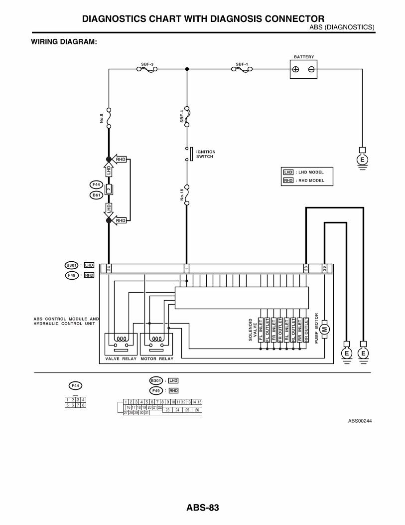
ABS (DIAGNOSTICS)DIAGNOSTICS CHART WITH DIAGNOSIS CONNECTOR
WIRING DIAGRAM:
ABS00244
EE
26
24
23
ABS CONTROL MODULE ANDHYDRAULIC CONTROL UNIT
VALVE RELAY
1
MOTOR RELAY
SO
LE
NO
ID
VA
LV
E
PU
MP
M
OT
OR
M
FL
IN
LE
T
RL
IN
LE
T
FR
IN
LE
T
RR
IN
LE
T
FL
OU
TL
ET
RL
OU
TL
ET
FR
OU
TL
ET
RR
OU
TL
ET
BATTERY
SBF-1SBF-3
SB
F-4
No
.18
No
.8
EIGNITIONSWITCH
F44
B61
2
1 2 3 45 6 7 8
F44
1 2 3 4 5 6 7 8 9 10 11 12 13 14 1516 17 18 19 20 21 22
27 28 29 30 3123 24 25 26
: LHD MODEL
: RHD MODEL
LHD
RHD
B301
F49
LHD
RHD
:
:
B301
F49
LHD
RHD
:
:
RHD
RHD
LH
DL
HD
ABS-83
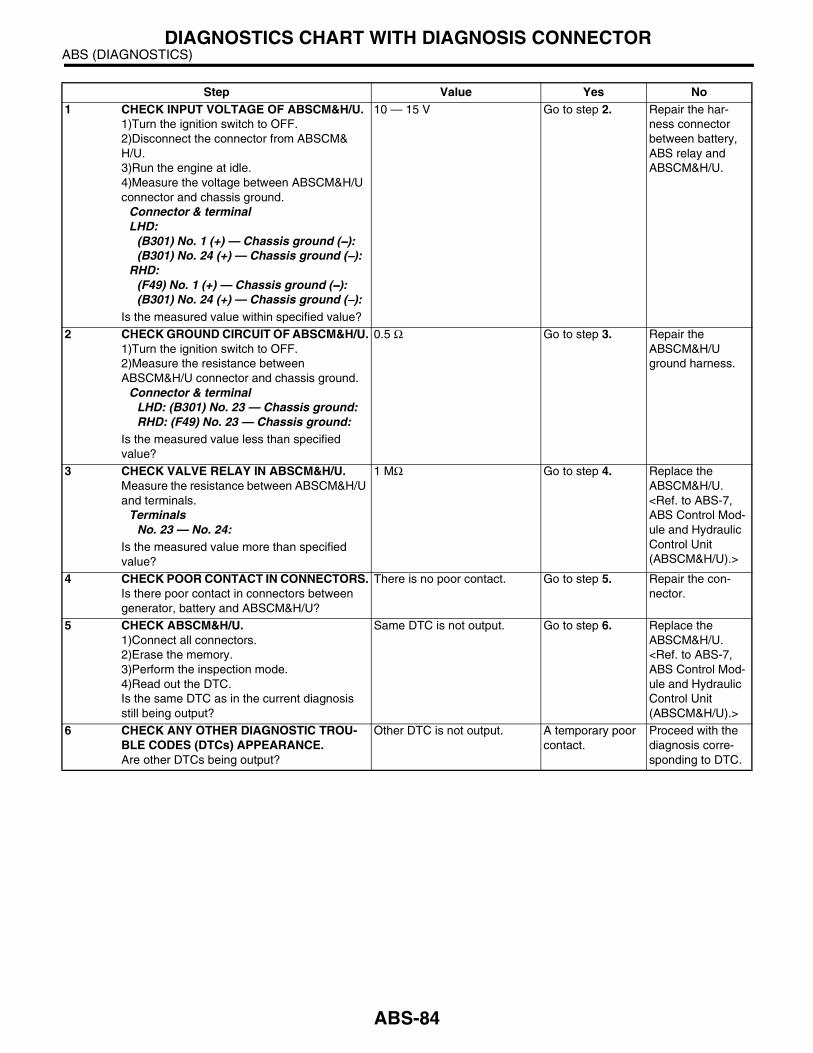
ABS (DIAGNOSTICS)DIAGNOSTICS CHART WITH DIAGNOSIS CONNECTOR
Step Value Yes No1 CHECK INPUT VOLTAGE OF ABSCM&H/U.
1)Turn the ignition switch to OFF.2)Disconnect the connector from ABSCM&H/U.3)Run the engine at idle.4)Measure the voltage between ABSCM&H/U connector and chassis ground.
Connector & terminalLHD:
(B301) No. 1 (+) — Chassis ground (−−−−):(B301) No. 24 (+) — Chassis ground (−−−−):
RHD: (F49) No. 1 (+) — Chassis ground (−−−−):(B301) No. 24 (+) — Chassis ground (−−−−):
Is the measured value within specified value?
10 — 15 V Go to step 2. Repair the har-ness connector between battery, ABS relay and ABSCM&H/U.
2 CHECK GROUND CIRCUIT OF ABSCM&H/U.1)Turn the ignition switch to OFF.2)Measure the resistance between ABSCM&H/U connector and chassis ground.
Connector & terminalLHD: (B301) No. 23 — Chassis ground:RHD: (F49) No. 23 — Chassis ground:
Is the measured value less than specified value?
0.5 Ω Go to step 3. Repair the ABSCM&H/U ground harness.
3 CHECK VALVE RELAY IN ABSCM&H/U.Measure the resistance between ABSCM&H/U and terminals.
TerminalsNo. 23 — No. 24:
Is the measured value more than specified value?
1 MΩ Go to step 4. Replace the ABSCM&H/U. <Ref. to ABS-7, ABS Control Mod-ule and Hydraulic Control Unit (ABSCM&H/U).>
4 CHECK POOR CONTACT IN CONNECTORS.Is there poor contact in connectors between generator, battery and ABSCM&H/U?
There is no poor contact. Go to step 5. Repair the con-nector.
5 CHECK ABSCM&H/U.1)Connect all connectors.2)Erase the memory.3)Perform the inspection mode.4)Read out the DTC.Is the same DTC as in the current diagnosis still being output?
Same DTC is not output. Go to step 6. Replace the ABSCM&H/U. <Ref. to ABS-7, ABS Control Mod-ule and Hydraulic Control Unit (ABSCM&H/U).>
6 CHECK ANY OTHER DIAGNOSTIC TROU-BLE CODES (DTCs) APPEARANCE.Are other DTCs being output?
Other DTC is not output. A temporary poor contact.
Proceed with the diagnosis corre-sponding to DTC.
ABS-84

ABS (DIAGNOSTICS)DIAGNOSTICS CHART WITH DIAGNOSIS CONNECTOR
Z: DTC 52 — ABNORMAL MOTOR AND/OR MOTOR RELAY —
DIAGNOSIS:• Faulty motor• Faulty motor relay• Faulty harness connectorTROUBLE SYMPTOM:• ABS does not operate.WIRING DIAGRAM:
ABS00249
EE
26
25
23
ABS CONTROL MODULE ANDHYDRAULIC CONTROL UNIT
VALVE RELAY
1
MOTOR RELAY
SO
LE
NO
ID
VA
LV
E
PU
MP
M
OT
OR
M
FL
IN
LE
T
RL
IN
LE
T
FR
IN
LE
T
RR
IN
LE
T
FL
OU
TL
ET
RL
OU
TL
ET
FR
OU
TL
ET
RR
OU
TL
ET
BATTERY
SBF-1
SB
F-4
SB
F
HO
LD
ER
No
.18
EIGNITIONSWITCH
F44
B61
1
1 2 3 45 6 7 8
F44
1 2 3 4 5 6 7 8 9 10 11 12 13 14 1516 17 18 19 20 21 22
27 28 29 30 3123 24 25 26
B301
F49
LHD
RHD
:
:
B301
F49
LHD
RHD
:
:
: LHD MODEL
: RHD MODEL
LHD
RHD
RHD
LH
DL
HD
RHD
4
F96
B255
B61
F44
ABS-85

ABS (DIAGNOSTICS)DIAGNOSTICS CHART WITH DIAGNOSIS CONNECTOR
Step Value Yes No1 CHECK INPUT VOLTAGE OF ABSCM&H/U.
1)Turn the ignition switch to OFF.2)Disconnect the connector from ABSCM&H/U.3)Turn the ignition switch to ON.4)Measure the voltage between ABSCM&H/U connector and chassis ground.
Connector & terminalLHD: (B301) No. 25 (+) — Chassis ground (−−−−):RHD: (F49) No. 25 (+) — Chassis ground (−−−−):
Is the measured value within specified value?
10 — 15 V Go to step 2. Repair the har-ness/connector between battery and ABSCM&H/U and check fuse SBF-holder.
2 CHECK GROUND CIRCUIT OF MOTOR.1)Turn the ignition switch to OFF.2)Measure the resistance between ABSCM&H/U connector and chassis ground.
Connector & terminalLHD: (B301) No. 26 — Chassis ground:RHD: (F49) No. 26 — Chassis ground:
Is the measured value less than specified value?
0.5 Ω Go to step 3. Repair the ABSCM&H/U ground harness.
3 CHECK INPUT VOLTAGE OF ABSCM&H/U.1)Run the engine at idle.2)Measure the voltage between ABSCM&H/U connector and chassis ground.
Connector & terminalLHD: (B301) No. 1 (+) — Chassis ground (−−−−):RHD: (F49) No. 1 (+) — Chassis ground (−−−−):
Is the measured value within specified value?
10 — 15 V Go to step 4. Repair the har-ness connector between battery, ignition switch and ABSCM&H/U.
4 CHECK GROUND CIRCUIT OF ABSCM&H/U.1)Turn the ignition switch to OFF.2)Measure the resistance between ABSCM&H/U connector and chassis ground.
Connector & terminalLHD: (B301) No. 23 — Chassis ground:RHD: (F49) No. 23 — Chassis ground:
Is the measured value less than specified value?
0.5 Ω Go to step 5. Repair the ABSCM&H/U ground harness.
5 CHECK MOTOR OPERATION.Operate the sequence control. <Ref. to ABS-11, ABS Sequence Control.>
NOTE:Use the diagnosis connector to operate the se-quence control.
Can motor revolution noise (buzz) be heard when carrying out the sequence control?
Motor revolution noise (buzz) can be heard.
Go to step 6. Replace the ABSCM&H/U. <Ref. to ABS-7, ABS Control Mod-ule and Hydraulic Control Unit (ABSCM&H/U).>
6 CHECK POOR CONTACT IN CONNECTORS.Turn the ignition switch to OFF.Is there poor contact in connector between generator, battery and ABSCM&H/U?
There is no poor contact. Go to step 7. Repair the con-nector.
ABS-86
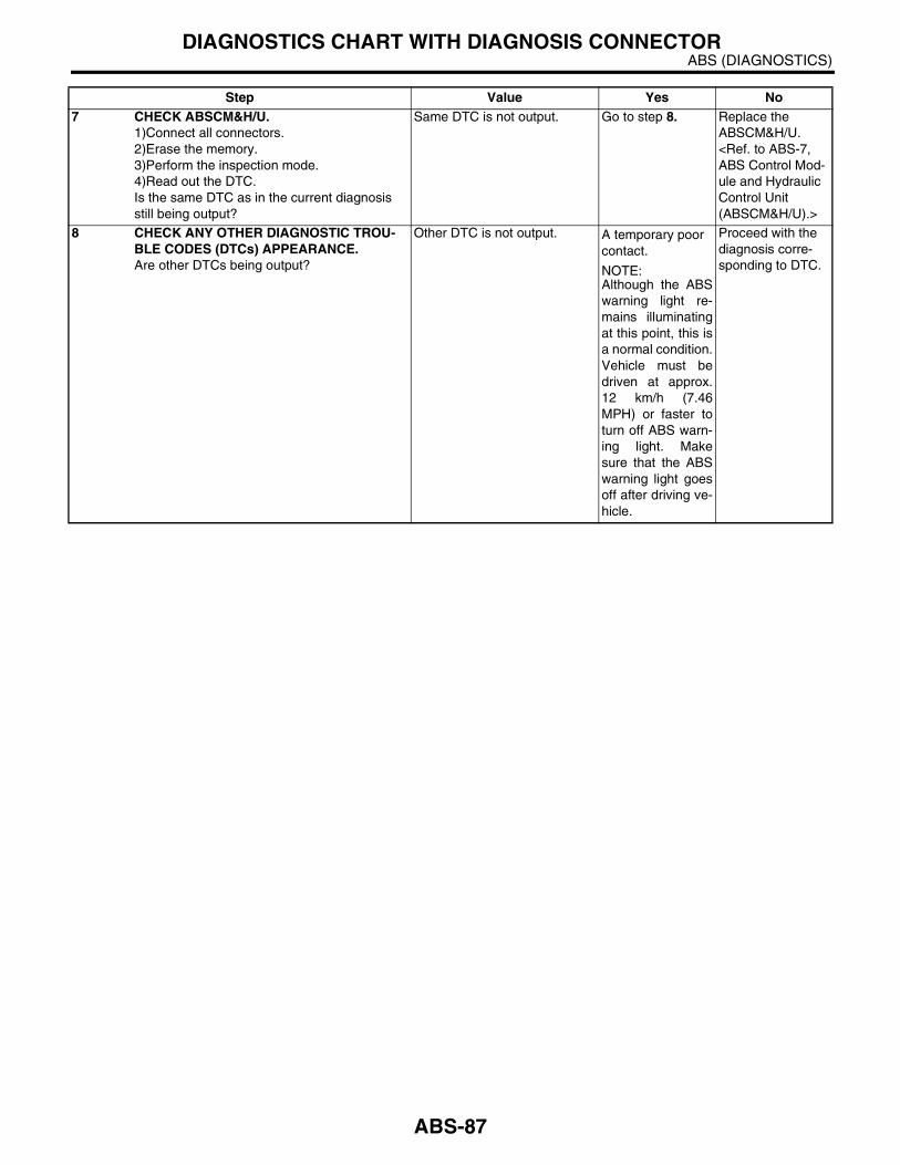
ABS (DIAGNOSTICS)DIAGNOSTICS CHART WITH DIAGNOSIS CONNECTOR
7 CHECK ABSCM&H/U.1)Connect all connectors.2)Erase the memory.3)Perform the inspection mode.4)Read out the DTC.Is the same DTC as in the current diagnosis still being output?
Same DTC is not output. Go to step 8. Replace the ABSCM&H/U. <Ref. to ABS-7, ABS Control Mod-ule and Hydraulic Control Unit (ABSCM&H/U).>
8 CHECK ANY OTHER DIAGNOSTIC TROU-BLE CODES (DTCs) APPEARANCE.Are other DTCs being output?
Other DTC is not output. A temporary poor contact.
NOTE:Although the ABSwarning light re-mains illuminatingat this point, this isa normal condition.Vehicle must bedriven at approx.12 km/h (7.46MPH) or faster toturn off ABS warn-ing light. Makesure that the ABSwarning light goesoff after driving ve-hicle.
Proceed with the diagnosis corre-sponding to DTC.
Step Value Yes No
ABS-87
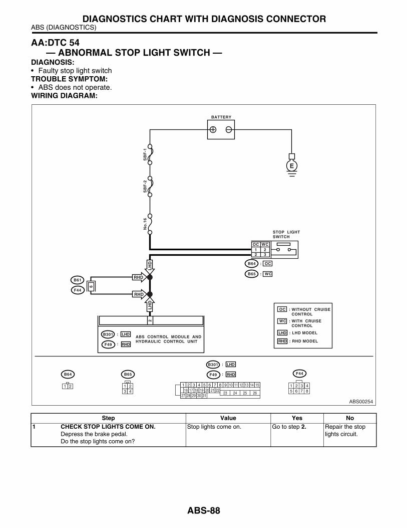
ABS (DIAGNOSTICS)DIAGNOSTICS CHART WITH DIAGNOSIS CONNECTOR
AA:DTC 54 — ABNORMAL STOP LIGHT SWITCH —
DIAGNOSIS:• Faulty stop light switchTROUBLE SYMPTOM:• ABS does not operate.WIRING DIAGRAM:
Step Value Yes No1 CHECK STOP LIGHTS COME ON.
Depress the brake pedal.Do the stop lights come on?
Stop lights come on. Go to step 2. Repair the stop lights circuit.
ABS00254
BATTERY
SB
F-1
SB
F-2
No
.16
B64
1 22 3
OC
OC
:
E
2
ABS CONTROL MODULE ANDHYDRAULIC CONTROL UNIT
STOP LIGHTSWITCH
B65 WC
WC
:
OC WITHOUT CRUISECONTROL
WITH CRUISECONTROL
:
WC :
B64 B65
1 2 1 2 3 4 5 6 7 8 9 10 11 12 13 14 1516 17 18 19 20 21 22
27 28 29 30 3123 24 25 26
1 23 4
: LHD MODEL
: RHD MODEL
LHD
RHD
B301
F49
LHD
RHD
:
:
B301
F49
LHD
RHD
:
:
RHD
LH
D
6
B61
F44
RHD
LH
D
F44
1 45 6 7 8
2 3
ABS-88

ABS (DIAGNOSTICS)DIAGNOSTICS CHART WITH DIAGNOSIS CONNECTOR
2 CHECK OPEN CIRCUIT IN HARNESS.1)Turn the ignition switch to OFF.2)Disconnect the connector from ABSCM&H/U.3)Depress the brake pedal.4)Measure the voltage between ABSCM&H/U connector and chassis ground.
Connector & terminalLHD: (B301) No. 2 (+) — Chassis ground (−−−−):RHD: (F49) No. 2 (+) — Chassis ground (−−−−):
Is the measured value within specified value?
10 — 15 V Go to step 3. Repair the har-ness between stop light switch and ABSCM&H/U.
3 CHECK POOR CONTACT IN CONNECTORS.Is there poor contact in connector between stop light switch and ABSCM&H/U?
There is no poor contact. Go to step 4. Repair the con-nector.
4 CHECK ABSCM&H/U.1)Connect all connectors.2)Erase the memory.3)Perform the inspection mode.4)Read out the DTC.Is the same DTC as in the current diagnosis still being output?
Same DTC is not output. Go to step 5. Replace the ABSCM&H/U. <Ref. to ABS-7, ABS Control Mod-ule and Hydraulic Control Unit (ABSCM&H/U).>
5 CHECK ANY OTHER DIAGNOSTIC TROU-BLE CODES (DTCs) APPEARANCE.Are other DTCs being output?
Other DTC is not output. A temporary poor contact.
Proceed with the diagnosis corre-sponding to DTC.
Step Value Yes No
ABS-89

ABS (DIAGNOSTICS)DIAGNOSTICS CHART WITH DIAGNOSIS CONNECTOR
AB:DTC 56 — ABNORMAL G SENSOR OUTPUT VOLTAGE —
DIAGNOSIS:• Faulty G sensor output voltageTROUBLE SYMPTOM:• ABS does not operate.WIRING DIAGRAM:LHD MODEL
ABS00259
ABS CONTROL MODULE ANDHYDRAULIC CONTROL UNITB301
F103 B301
1 2 3 4 5 6 7 8 9 10 11 12 13 14 1516 17 18 19 20 21 22
27 28 29 30 3123 24 25 26
1 2 3 45 6 7 8
28
30 6 23
F103
B292
ABSG SENSOR
E
E
2
321
B292
1 2 3
SHIELD JOINTCONNECTOR
ABS-90

ABS (DIAGNOSTICS)DIAGNOSTICS CHART WITH DIAGNOSIS CONNECTOR
RHD MODEL
ABS00264
ABS CONTROL MODULE ANDHYDRAULIC CONTROL UNITF49
F48 F49
1 2 3 4 5 6 7 8 9 10 11 12 13 14 1516 17 18 19 20 21 22
27 28 29 30 3123 24 25 26
1 2 3 45 6 7 8
28
30 6 23
F48
B292
ABSG SENSOR
E
321
B292
1 2 3
SHIELD JOINTCONNECTOR
85
9
F45
B62
210 1
10 11 12 13 14 15 16 17 181 2 3 4 7 85 69
F45
Step Value Yes No1 CHECK ALL FOUR WHEELS FOR FREE
TURNING.Have the wheels been turned freely such as when the vehicle is lifted up, or operated on a free roller or rolling road?
Wheels have not been turned freely.
Go to step 2. The ABS is nor-mal. Erase the DTC.
ABS-91
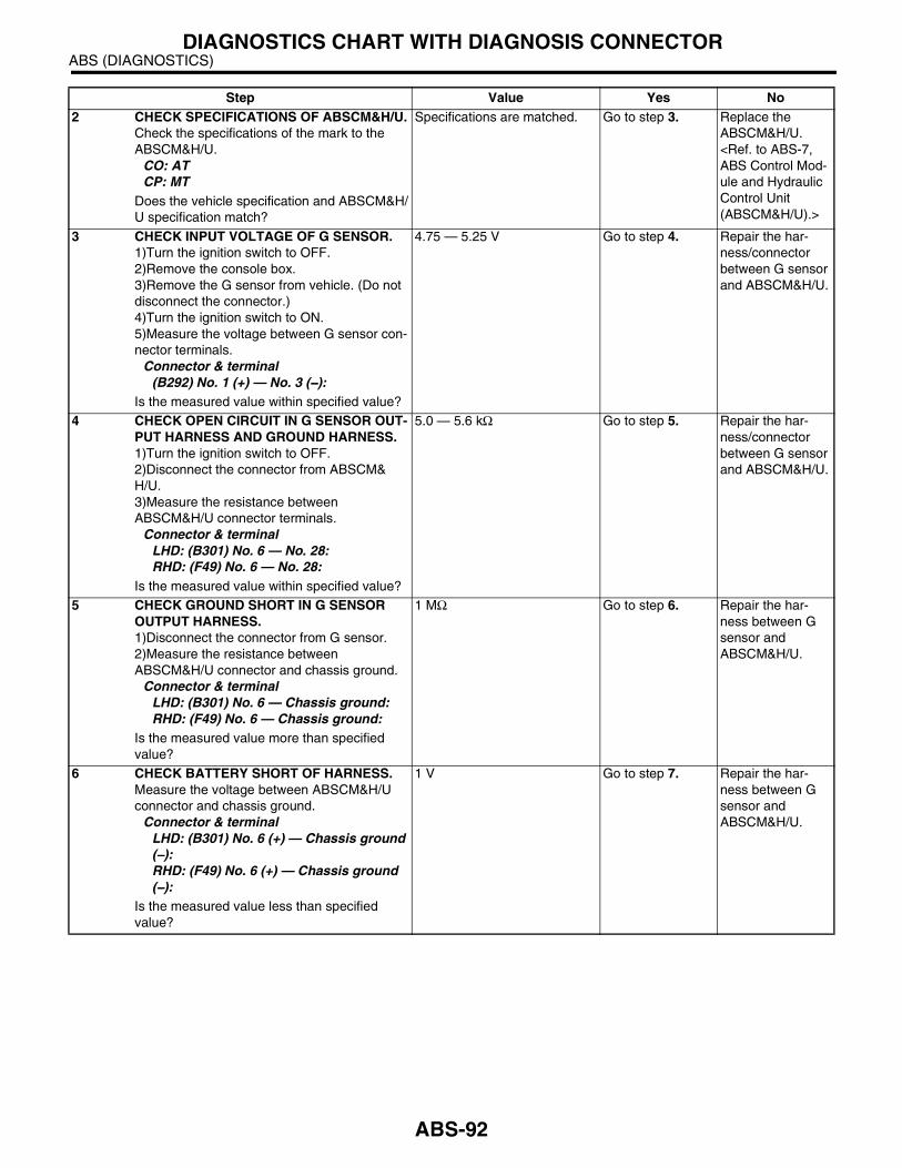
ABS (DIAGNOSTICS)DIAGNOSTICS CHART WITH DIAGNOSIS CONNECTOR
2 CHECK SPECIFICATIONS OF ABSCM&H/U.Check the specifications of the mark to the ABSCM&H/U.
CO: ATCP: MT
Does the vehicle specification and ABSCM&H/U specification match?
Specifications are matched. Go to step 3. Replace the ABSCM&H/U. <Ref. to ABS-7, ABS Control Mod-ule and Hydraulic Control Unit (ABSCM&H/U).>
3 CHECK INPUT VOLTAGE OF G SENSOR.1)Turn the ignition switch to OFF.2)Remove the console box.3)Remove the G sensor from vehicle. (Do not disconnect the connector.)4)Turn the ignition switch to ON.5)Measure the voltage between G sensor con-nector terminals.
Connector & terminal(B292) No. 1 (+) — No. 3 (−−−−):
Is the measured value within specified value?
4.75 — 5.25 V Go to step 4. Repair the har-ness/connector between G sensor and ABSCM&H/U.
4 CHECK OPEN CIRCUIT IN G SENSOR OUT-PUT HARNESS AND GROUND HARNESS.1)Turn the ignition switch to OFF.2)Disconnect the connector from ABSCM&H/U.3)Measure the resistance between ABSCM&H/U connector terminals.
Connector & terminalLHD: (B301) No. 6 — No. 28:RHD: (F49) No. 6 — No. 28:
Is the measured value within specified value?
5.0 — 5.6 kΩ Go to step 5. Repair the har-ness/connector between G sensor and ABSCM&H/U.
5 CHECK GROUND SHORT IN G SENSOR OUTPUT HARNESS.1)Disconnect the connector from G sensor.2)Measure the resistance between ABSCM&H/U connector and chassis ground.
Connector & terminalLHD: (B301) No. 6 — Chassis ground:RHD: (F49) No. 6 — Chassis ground:
Is the measured value more than specified value?
1 MΩ Go to step 6. Repair the har-ness between G sensor and ABSCM&H/U.
6 CHECK BATTERY SHORT OF HARNESS.Measure the voltage between ABSCM&H/U connector and chassis ground.
Connector & terminalLHD: (B301) No. 6 (+) — Chassis ground (−−−−):RHD: (F49) No. 6 (+) — Chassis ground (−−−−):
Is the measured value less than specified value?
1 V Go to step 7. Repair the har-ness between G sensor and ABSCM&H/U.
Step Value Yes No
ABS-92

ABS (DIAGNOSTICS)DIAGNOSTICS CHART WITH DIAGNOSIS CONNECTOR
7 CHECK BATTERY SHORT OF HARNESS.1)Turn the ignition switch to ON.2)Measure the voltage between ABSCM&H/U connector and chassis ground.
Connector & terminalLHD: (B301) No. 6 (+) — Chassis ground (−−−−):RHD: (F49) No. 6 (+) — Chassis ground (−−−−):
Is the measured value less than specified value?
1 V Go to step 8. Repair the har-ness between G sensor and ABSCM&H/U.
8 CHECK GROUND SHORT OF HARNESS.Measure the resistance between ABSCM&H/U connector and chassis ground.
Connector & terminalLHD: (B301) No. 28 — Chassis ground:RHD: (F49) No. 28 — Chassis ground:
Is the measured value more than specified value?
1 MΩ Go to step 9. Repair the har-ness between G sensor and ABSCM&H/U.Replace the ABSCM&H/U. <Ref. to ABS-7, ABS Control Mod-ule and Hydraulic Control Unit (ABSCM&H/U).>
9 CHECK G SENSOR.1)Turn the ignition switch to OFF.2)Remove the G sensor from vehicle.3)Connect the connector to G sensor.4)Connect the connector to ABSCM&H/U.5)Turn the ignition switch to ON.6)Measure the voltage between G sensor con-nector terminals.
Connector & terminal(B292) No. 2 (+) — No. 3 (−−−−):
Is the measured value within specified value when G sensor is horizontal?
2.1 — 2.4 V Go to step 10. Replace the G sensor. <Ref. to ABS-22, G Sen-sor.>
10 CHECK G SENSOR.Measure the voltage between G sensor con-nector terminals.
Connector & terminal(B292) No. 2 (+) — No. 3 (−−−−):
Is the measured value within specified value when G sensor is inclined forwards to 90°?
3.7 — 4.1 V Go to step 11. Replace the G sensor. <Ref. to ABS-22, G Sen-sor.>
11 CHECK G SENSOR.Measure the voltage between G sensor con-nector terminals.
Connector & terminal(B292) No. 2 (+) — No. 3 (−−−−):
Is the measured value within specified value when G sensor is inclined backwards to 90°?
0.5 — 0.9 V Go to step 12. Replace the G sensor. <Ref. to ABS-22, G Sen-sor.>
12 CHECK POOR CONTACT IN CONNECTORS.Is there poor contact in connector between ABSCM&H/U and G sensor?
There is no poor contact. Go to step 13. Repair the con-nector.
13 CHECK ABSCM&H/U.1)Connect all connectors.2)Erase the memory.3)Perform inspection mode.4)Read out the DTC.Is the same DTC as in the current diagnosis still being output?
Same DTC is not output. Go to step 14. Replace the ABSCM&H/U. <Ref. to ABS-7, ABS Control Mod-ule and Hydraulic Control Unit (ABSCM&H/U).>
Step Value Yes No
ABS-93
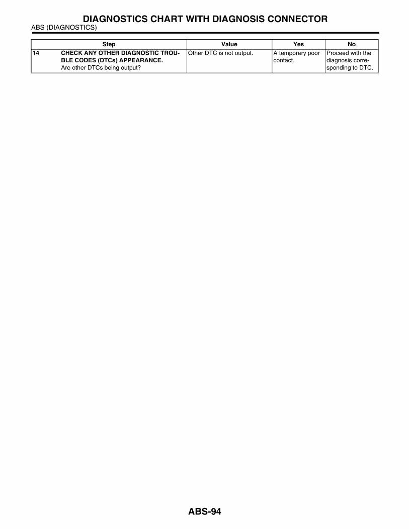
ABS (DIAGNOSTICS)DIAGNOSTICS CHART WITH DIAGNOSIS CONNECTOR
14 CHECK ANY OTHER DIAGNOSTIC TROU-BLE CODES (DTCs) APPEARANCE.Are other DTCs being output?
Other DTC is not output. A temporary poor contact.
Proceed with the diagnosis corre-sponding to DTC.
Step Value Yes No
ABS-94

ABS (DIAGNOSTICS)DIAGNOSTICS CHART WITH SUBARU SELECT MONITOR
13.Diagnostics Chart with Subaru Select MonitorA: COMMUNICATION FOR INITIALIZING IMPOSSIBLE DIAGNOSIS:• Faulty harness connectorTROUBLE SYMPTOM:• ABS warning light remains on.WIRING DIAGRAM:
ABS00269
ABS CONTROL MODULE AND HYDRAULIC CONTROL UNIT
1 2 3 4 5 6 7 8 9 10 11 12 13 14 1516 17 18 19 20 21 22
27 28 29 30 3123 24 25 26
BATTERY
SB
F-1
SB
F-4
No
.18
GENERATOR
B40
E
E
4
5
DATA LINKCONNECTOR
5 20
231
IGNITIONSWITCH
B40
1 2 3 4 5 6 7 8
9 10 11 12 13 14 15 16
B301
F49
LHD
RHD
:
:
: LHD MODEL
: RHD MODEL
LHD
RHD
10 11 12 13 14 15 16 17 181 2 3 4 7 85 69
F45
RH
D
LHD
RH
D
LHDRH
D
LHD
RH
D
LHD
65
B301
F49
LHD
RHD
:
:
F45 B62
ABS-95
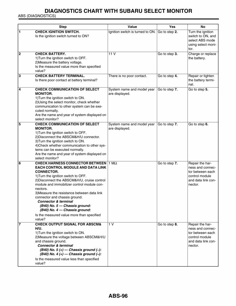
ABS (DIAGNOSTICS)DIAGNOSTICS CHART WITH SUBARU SELECT MONITOR
Step Value Yes No1 CHECK IGNITION SWITCH.
Is the ignition switch turned to ON?Ignition switch is turned to ON. Go to step 2. Turn the ignition
switch to ON, and select ABS mode using select moni-tor.
2 CHECK BATTERY.1)Turn the ignition switch to OFF.2)Measure the battery voltage.Is the measured value more than specified value?
11 V Go to step 3. Charge or replace the battery.
3 CHECK BATTERY TERMINAL.Is there poor contact at battery terminal?
There is no poor contact. Go to step 4. Repair or tighten the battery termi-nal.
4 CHECK COMMUNICATION OF SELECT MONITOR.1)Turn the ignition switch to ON.2)Using the select monitor, check whether communication to other system can be exe-cuted normally.Are the name and year of system displayed on select monitor?
System name and model year are displayed.
Go to step 7. Go to step 5.
5 CHECK COMMUNICATION OF SELECT MONITOR.1)Turn the ignition switch to OFF.2)Disconnect the ABSCM&H/U connector.3)Turn the ignition switch to ON.4)Check whether communication to other sys-tems can be executed normally.Are the name and year of system displayed on select monitor?
System name and model year are displayed.
Go to step 7. Go to step 6.
6 CHECK HARNESS CONNECTOR BETWEEN EACH CONTROL MODULE AND DATA LINK CONNECTOR.1)Turn the ignition switch to OFF.2)Disconnect the ABSCM&H/U, cruise control module and immobilizer control module con-nectors.3)Measure the resistance between data link connector and chassis ground.
Connector & terminal(B40) No. 5 — Chassis ground:(B40) No. 4 — Chassis ground:
Is the measured value more than specified value?
1 MΩ Go to step 7. Repair the har-ness and connec-tor between each control module and data link con-nector.
7 CHECK OUTPUT SIGNAL FOR ABSCM&H/U.1)Turn the ignition switch to ON.2)Measure the voltage between ABSCM&H/U and chassis ground.
Connector & terminal(B40) No. 5 (+) — Chassis ground (−−−−):(B40) No. 4 (+) — Chassis ground (−−−−):
Is the measured value less than specified value?
1 V Go to step 8. Repair the har-ness and connec-tor between each control module and data link con-nector.
ABS-96

ABS (DIAGNOSTICS)DIAGNOSTICS CHART WITH SUBARU SELECT MONITOR
8 CHECK HARNESS/CONNECTOR BETWEEN ABSCM&H/U AND DATA LINK CONNEC-TOR.Measure the resistance between ABSCM&H/U connector and data link connector.
Connector & terminalLHD:
(B301) No. 20 — (B40) No. 5: (B301) No. 5 — (B40) No. 4:
RHD: (F49) No. 20 — (B40) No. 5: (F49) No. 5 — (B40) No. 4:
Is the measured value less than specified value?
0.5 Ω Go to step 9. Repair the har-ness and connec-tor between ABSCM&H/U and data link connec-tor.
9 CHECK INSTALLATION OF ABSCM&H/U CONNECTOR.Turn the ignition switch to OFF.Is the ABSCM&H/U connector inserted into ABSCM&H/U until the clamp locks onto it?
Correctly installed. Go to step 10. Insert the ABSCM&H/U con-nector into ABSCM&H/U.
10 CHECK POWER SUPPLY CIRCUIT.1)Turn the ignition switch to ON (engine OFF).2)Measure the ignition power supply voltage between ABSCM&H/U connector and chassis ground.
Connector & terminalLHD: (B301) No. 1 (+) — Chassis ground (−−−−):RHD: (F49) No. 1 (+) — Chassis ground (−−−−):
Is the measured value more than specified value?
10 V Go to step 11. Repair the open circuit in harness between ABSCM&H/U and battery.
11 CHECK HARNESS CONNECTOR BETWEEN ABSCM&H/U AND CHASSIS GROUND.1)Turn the ignition switch to OFF.2)Disconnect the connector from ABSCM&H/U and transmission.3)Measure the resistance of harness between ABSCM&H/U and chassis ground.
Connector & terminalLHD: (B301) No. 23 — Chassis ground:RHD: (F49) No. 23 — Chassis ground:
Is the measured value less than specified value?
1 Ω Go to step 12. Repair the open circuit in harness between ABSCM&H/U and inhibitor side con-nector, and poor contact in cou-pling connector.
12 CHECK POOR CONTACT IN CONNECTORS.Is there poor contact in control module power supply, ground line and data link connector?
There is no poor contact. Repair the con-nector.
Replace the ABSCM&H/U. <Ref. to ABS-7, ABS Control Mod-ule and Hydraulic Control Unit (ABSCM&H/U).>
Step Value Yes No
ABS-97
ABS (DIAGNOSTICS)DIAGNOSTICS CHART WITH SUBARU SELECT MONITOR
B: NO TROUBLE CODEDIAGNOSIS:• ABS warning light circuit is shorted.TROUBLE SYMPTOM:• ABS warning light remains on.• NO TROUBLE CODE displayed on the select monitor.
NOTE:When the ABS warning light is OFF and “NO TROUBLE CODE” is displayed on select monitor, the systemis in normal condition.
ABS-98

ABS (DIAGNOSTICS)DIAGNOSTICS CHART WITH SUBARU SELECT MONITOR
WIRING DIAGRAM:LHD MODEL
22
ABS00199
BATTERY
IGNITIONSWITCH
SBF-3 SBF-1
SB
F-4
B37
No.14
No
.18
No
.8
i2
i10B :
i12A :
C : i11
i2
B37
BR
AK
EW
AR
NIN
GL
IGH
T
COMBINATIONMETER
DIAGNOSISTERMINAL
E
EE
5B
9
6A7
C6
124 4 23
21
B82
B81
B301
B82
B36i11C :
i10B : i12A :
1 2 3 4 5 6 7 8 9 1012 13 14 15 16 17 18 19 20 21 22 23 24
1 2 3 4 5 6 7 8 9 10 11 12 13 1415 16 17 18 19 20 21 22 23 24 25 26 27 28 29 30
1 2 3 4 5 6 7 8 9 10 111 2 3 4 5 6 7 8 9 10 11 12 13 14 1516 17 18 19 20 21 22
27 28 29 30 3123 24 25 26
AB
SW
AR
NIN
GL
IGH
T
ABS CONTROL MODULE AND HYDRAULIC CONTROL UNITB301
1 2987 103
11 12 13 144 5 6 1 2
3 4 5 6
9 23
i3
B38
B51
B158
24
FUSE &RELAYBOX
219
32
1 2 3 4 5 610 11 12 13 14 15
716
23 3019 20
22 26 27 28 29
817
24 3118
25
B38
ABS-99

ABS (DIAGNOSTICS)DIAGNOSTICS CHART WITH SUBARU SELECT MONITOR
RHD MODEL
22
ABS00204
BATTERY
IGNITIONSWITCH
SBF-3 SBF-1
SB
F-4
B38
No.14
No
.18
No
.8
i3
i10B :
i12A :
C : i11
B62
F45
BR
AK
EW
AR
NIN
GL
IGH
T
COMBINATIONMETER
DIAGNOSISTERMINAL
E
EE
B9
6
A7
C6
14 13
124 4 23
21
B82
B81
F49
B82
B36i11C :
i10B : i12A :
1 2 3 4 5 6 7 8 9 10 12 13 14 15 16 17 18 19 20 21 22 23 24
1 2 3 4 5 6 7 8 9 10 11 12 13 1415 16 17 18 19 20 21 22 23 24 25 26 27 28 29 30
1 2 3 4 5 6 7 8 9 10 111 2 3 4 5 6 7 8 9 10 11 12 13 14 1516 17 18 19 20 21 22
27 28 29 30 3123 24 25 26
AB
SW
AR
NIN
GL
IGH
T
ABS CONTROL MODULE AND HYDRAULIC CONTROL UNITF49
1 2987 103
11 12 13 144 5 6 1 2
3 4 5 6
16
3B62
F45
10 11 12 13 14 15 16 17 181 2 3 4 7 85 69
F45
Step Value Yes No1 CHECK WIRING HARNESS.
1)Turn the ignition switch to OFF.2)Disconnect the connector (i2) or (B62) from connector (B37) or (F45).3)Turn ignition switch to ON.Does the ABS warning light turn on?
ABS warning light does not turn on.
Go to step 2. Repair the front wiring harness.
ABS-100

ABS (DIAGNOSTICS)DIAGNOSTICS CHART WITH SUBARU SELECT MONITOR
2 CHECK PROJECTION AT ABSCM&H/U.1)Turn the ignition switch to OFF.2)Disconnect the connector from ABSCM&H/U.3)Check for broken at the ABSCM&H/U.
Terminal is not broken. Go to step 3. Replace the ABSCM&H/U. <Ref. to ABS-7, ABS Control Mod-ule and Hydraulic Control Unit (ABSCM&H/U).>
3 CHECK ABSCM&H/U.Measure the resistance between ABSCM&H/U terminals.
TerminalsNo. 22 — No. 23:
Is the measured value more than specified value?
1 MΩ Go to step 4. Replace the ABSCM&H/U. <Ref. to ABS-7, ABS Control Mod-ule and Hydraulic Control Unit (ABSCM&H/U).>
4 CHECK WIRING HARNESS.Measure the resistance between connector and chassis ground.
Connector & terminalLHD: (B301) No. 22 — Chassis ground:RHD: (F49) No. 22 — Chassis ground:
Is the measured value less than specified value?
0.5 Ω Go to step 5. Repair the har-ness.
5 CHECK WIRING HARNESS.1)Connect the connector to ABSCM&H/U.2)Measure the resistance between connector and chassis ground.
Connector & terminalLHD: (B301) No. 22 — Chassis ground:RHD: (F49) No. 22 — Chassis ground:
Is the measured value more than specified value?
1 MΩ Go to step 6. Repair the har-ness.
6 CHECK POOR CONTACT IN ABSCM&H/U CONNECTOR.Is there poor contact in ABSCM&H/U connec-tor?
There is no poor contact. Replace the ABSCM&H/U. <Ref. to ABS-7, ABS Control Mod-ule and Hydraulic Control Unit (ABSCM&H/U).>
Repair the con-nector.
Step Value Yes No
ABS-101

ABS (DIAGNOSTICS)DIAGNOSTICS CHART WITH SUBARU SELECT MONITOR
C: DTC 21 — OPEN OR SHORT CIRCUIT IN FRONT RIGHT ABS SENSOR CIRCUIT —
NOTE:For the diagnostic procedure, refer to DTC 27. <Ref. to ABS-103, DTC 27 — OPEN OR SHORT CIRCUITIN REAR LEFT ABS SENSOR CIRCUIT —, Diagnostics Chart with Subaru Select Monitor.>
D: DTC 23 — OPEN OR SHORT CIRCUIT IN FRONT LEFT ABS SENSOR CIRCUIT —
NOTE:For the diagnostic procedure, refer to DTC 27. <Ref. to ABS-103, DTC 27 — OPEN OR SHORT CIRCUITIN REAR LEFT ABS SENSOR CIRCUIT —, Diagnostics Chart with Subaru Select Monitor.>
E: DTC 25 — OPEN OR SHORT CIRCUIT IN REAR RIGHT ABS SENSOR CIRCUIT —
NOTE:For the diagnostic procedure, refer to DTC 27. <Ref. to ABS-103, DTC 27 — OPEN OR SHORT CIRCUITIN REAR LEFT ABS SENSOR CIRCUIT —, Diagnostics Chart with Subaru Select Monitor.>
ABS-102

ABS (DIAGNOSTICS)DIAGNOSTICS CHART WITH SUBARU SELECT MONITOR
F: DTC 27 — OPEN OR SHORT CIRCUIT IN REAR LEFT ABS SENSOR CIRCUIT —
DIAGNOSIS:• Faulty ABS sensor (Broken wire, input voltage too high)• Faulty harness connectorTROUBLE SYMPTOM:• ABS does not operate.WIRING DIAGRAM:LHD MODEL
ABS00219
ABS CONTROL MODULE AND HYDRAULIC CONTROL UNIT
SHIELD JOINTCONNECTOR
B301
15
14
109 87 23
F103
REAR ABSSENSOR RH
B98
R72
R2
E
17 6
3
54
19
1887
REAR ABSSENSOR LH
R73
FRONT ABSSENSOR RH
B6
21
21
TW
IST
ED
WIR
E
TW
IST
ED
WIR
E
21
FRONT ABSSENSOR LH
F94
B321
F103
F103 B98
B6
F94 R72
R73
21
2 1
B301
1 2 3 4 5 6 7 8 9 10 11 12 13 14 1516 17 18 19 20 21 22
27 28 29 30 3123 24 25 26
12
11
1 2 3 4 5 6 7 8 910 11 12 13 14 15 16 17 18 19 20
1 2 3 45 6 7 8
2 1
ABS-103

ABS (DIAGNOSTICS)DIAGNOSTICS CHART WITH SUBARU SELECT MONITOR
RHD MODEL
ABS00224
ABS CONTROL MODULE AND HYDRAULIC CONTROL UNIT
SHIELD JOINTCONNECTOR
F49
15
14
109 87 23
F48
REAR ABSSENSOR RH
B98
R72
R2
E
12
29
28
26
25
REAR ABSSENSOR LH
R73
FRONT ABSSENSOR RH
F95
21
21
TW
IST
ED
WIR
E
TW
IST
ED
WIR
E
21
FRONT ABSSENSOR LH
F94
F62 B98F95F94 R72 R73
21
2 1
F49
1 2 3 4 5 6 7 8 9 10 11 12 13 14 1516 17 18 19 20 21 22
27 28 29 30 3123 24 25 26
12
11
1 2 3 4 5 6 7 8 910 11 12 13 14 15 16 17 18 19 20
1 2 3 45 6 7 8
2 1
10 11 12 13 14 15 16 17 181 2 3 4 7 85 69
F45
F45
B62
18
1787 15
38
ABS-104

ABS (DIAGNOSTICS)DIAGNOSTICS CHART WITH SUBARU SELECT MONITOR
Step Value Yes No1 CHECK OUTPUT OF ABS SENSOR USING
SELECT MONITOR.1)Select “Current data display & Save” on the select monitor.2)Read the ABS sensor output corresponding to faulty system in the select monitor data dis-play mode.Does the speed indicated on display change in response to speedometer reading during acceleration/deceleration when the steering wheel is in straight-ahead position?
Speed indicated on display changes.
Go to step 2. Go to step 8.
2 CHECK INSTALLATION OF ABS SENSOR.Are the ABS sensor installation bolts tightened securely?
33 N·m (3.4 kgf-m, 24.6 ft-lb) Go to step 3. Tighten the ABS sensor installation bolts securely.
3 CHECK ABS SENSOR GAP.Measure the tone wheel to ABS sensor piece gap over entire perimeter of the wheel.Is the measured value within specified value?
Front wheel:0.3 — 0.8 mm (0.012 — 0.031 in)Rear wheel0.7 — 1.2 mm (0.028 — 0.047 in)
Go to step 4. Adjust the gap.
NOTE:Adjust the gap us-ing spacers (PartNo. 26755AA000).If the spacers can-not correct gap, re-place worn sensoror worn tonewheel.
4 CHECK TONE WHEEL RUNOUT.Measure the tone wheel runout.Is the measured value less than specified value?
0.05 mm (0.0020 in) Go to step 5. Replace the tone wheel. Front: <Ref. to ABS-20, Front Tone Wheel.> Rear: <Ref. to ABS-21, Rear Tone Wheel.>
5 CHECK POOR CONTACT IN CONNECTORS.Turn the ignition switch to OFF.Is there poor contact in connectors between ABSCM&H/U and ABS sensor?
There is no poor contact. Go to step 6. Repair the con-nector.
6 CHECK ABSCM&H/U.1)Connect all connectors.2)Erase the memory.3)Perform the inspection mode.4)Read out the DTC.Is the same DTC as in the current diagnosis still being output?
Same DTC is not output. Go to step 7. Replace the ABSCM&H/U. <Ref. to ABS-7, ABS Control Mod-ule and Hydraulic Control Unit (ABSCM&H/U).>
7 CHECK ANY OTHER DIAGNOSTIC TROU-BLE CODES (DTCs) APPEARANCE.Are other DTCs being output?
Other DTC is not output. A temporary poor contact.
NOTE:Check the harnessand connectorsbetween AB-SCM&H/U andABS sensor.
Proceed with the diagnosis corre-sponding to DTC.
ABS-105

ABS (DIAGNOSTICS)DIAGNOSTICS CHART WITH SUBARU SELECT MONITOR
8 CHECK ABS SENSOR.1)Turn the ignition switch to OFF.2)Disconnect the connector from ABS sensor.3)Measure the resistance of ABS sensor con-nector terminals while shaking the harness lightly.
TerminalFront RH No. 1 — No. 2:Front LH No. 1 — No. 2:Rear RH No. 1 — No. 2:Rear LH No. 1 — No. 2:
Is the measured value within specified value?
Front: 1 — 1.5 kΩRear: 1.025 — 1.265 kΩ
Go to step 9. Replace the ABS sensor. Front: <Ref. to ABS-14, Front ABS Sen-sor.> Rear: <Ref. to ABS-17, Rear ABS Sensor.>
9 CHECK BATTERY SHORT OF ABS SEN-SOR.1)Disconnect the connector from ABSCM&H/U.2)Measure the voltage between ABS sensor and chassis ground.
TerminalFront RH No. 1 (+) — Chassis ground (−−−−):Front LH No. 1 (+) — Chassis ground (−−−−):Rear RH No. 1 (+) — Chassis ground (−−−−):Rear LH No. 1 (+) — Chassis ground (−−−−):
Is the measured value less than specified value?
1 V Go to step 10. Replace the ABS sensor. Front: <Ref. to ABS-14, Front ABS Sen-sor.> Rear: <Ref. to ABS-17, Rear ABS Sensor.>
10 CHECK BATTERY SHORT OF ABS SEN-SOR.1)Turn the ignition switch to ON.2)Measure the voltage between ABS sensor and chassis ground.
TerminalFront RH No. 1 (+) — Chassis ground (−−−−):Front LH No. 1 (+) — Chassis ground (−−−−):Rear RH No. 1 (+) — Chassis ground (−−−−):Rear LH No. 1 (+) — Chassis ground (−−−−):
Is the measured value less than specified value?
1 V Go to step 11. Replace the ABS sensor. Front: <Ref. to ABS-14, Front ABS Sen-sor.> Rear: <Ref. to ABS-17, Rear ABS Sensor.>
11 CHECK HARNESS/CONNECTOR BETWEEN ABSCM&H/U AND ABS SENSOR.1)Turn the ignition switch to OFF.2)Connect the connector to ABS sensor.3)Measure the resistance between ABSCM&H/U connector terminals.
Connector & terminalDTC 21
LHD: (B301) No. 11 — No. 12:RHD: (F49) No. 11 — No. 12:
DTC 23LHD: (B301) No. 9 — No. 10:RHD: (F49) No. 9 — No. 10:
DTC 25LHD: (B301) No. 14 — No. 15:RHD: (F49) No. 14 — No. 15:
DTC 27LHD: (B301) No. 7 — No. 8:RHD: (F49) No. 7 — No. 8:
Is the measured value within specified value?
Front: 1 — 1.5 kΩRear: 1.025 — 1.265 kΩ
Go to step 12. Repair the har-ness/connector between ABSCM&H/U and ABS sensor.
Step Value Yes No
ABS-106
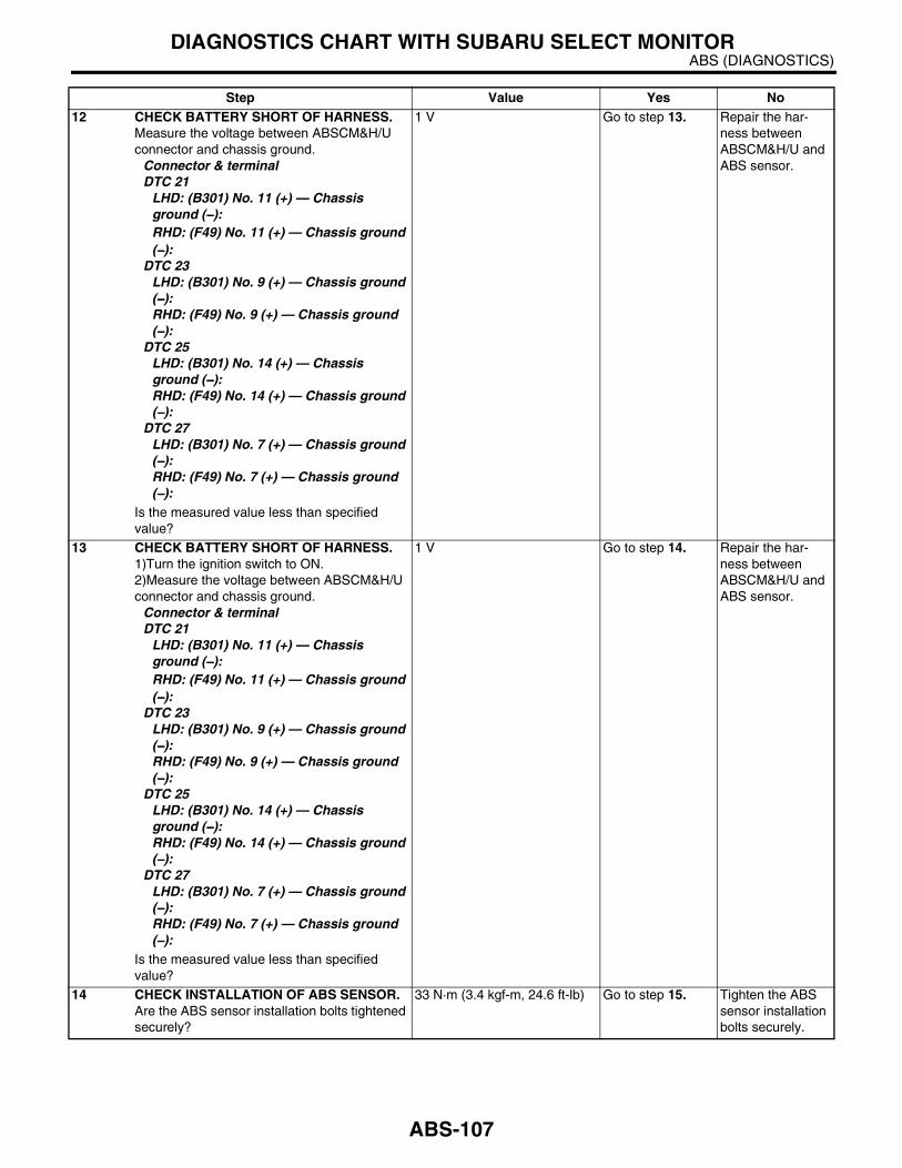
ABS (DIAGNOSTICS)DIAGNOSTICS CHART WITH SUBARU SELECT MONITOR
12 CHECK BATTERY SHORT OF HARNESS.Measure the voltage between ABSCM&H/U connector and chassis ground.
Connector & terminalDTC 21
LHD: (B301) No. 11 (+) — Chassis ground (−−−−):RHD: (F49) No. 11 (+) — Chassis ground (−−−−):
DTC 23LHD: (B301) No. 9 (+) — Chassis ground (−−−−):RHD: (F49) No. 9 (+) — Chassis ground (−−−−):
DTC 25LHD: (B301) No. 14 (+) — Chassis ground (−−−−):RHD: (F49) No. 14 (+) — Chassis ground (−−−−):
DTC 27LHD: (B301) No. 7 (+) — Chassis ground (−−−−):RHD: (F49) No. 7 (+) — Chassis ground (−−−−):
Is the measured value less than specified value?
1 V Go to step 13. Repair the har-ness between ABSCM&H/U and ABS sensor.
13 CHECK BATTERY SHORT OF HARNESS.1)Turn the ignition switch to ON.2)Measure the voltage between ABSCM&H/U connector and chassis ground.
Connector & terminalDTC 21
LHD: (B301) No. 11 (+) — Chassis ground (−−−−):RHD: (F49) No. 11 (+) — Chassis ground (−−−−):
DTC 23LHD: (B301) No. 9 (+) — Chassis ground (−−−−):RHD: (F49) No. 9 (+) — Chassis ground (−−−−):
DTC 25LHD: (B301) No. 14 (+) — Chassis ground (−−−−):RHD: (F49) No. 14 (+) — Chassis ground (−−−−):
DTC 27LHD: (B301) No. 7 (+) — Chassis ground (−−−−):RHD: (F49) No. 7 (+) — Chassis ground (−−−−):
Is the measured value less than specified value?
1 V Go to step 14. Repair the har-ness between ABSCM&H/U and ABS sensor.
14 CHECK INSTALLATION OF ABS SENSOR.Are the ABS sensor installation bolts tightened securely?
33 N·m (3.4 kgf-m, 24.6 ft-lb) Go to step 15. Tighten the ABS sensor installation bolts securely.
Step Value Yes No
ABS-107
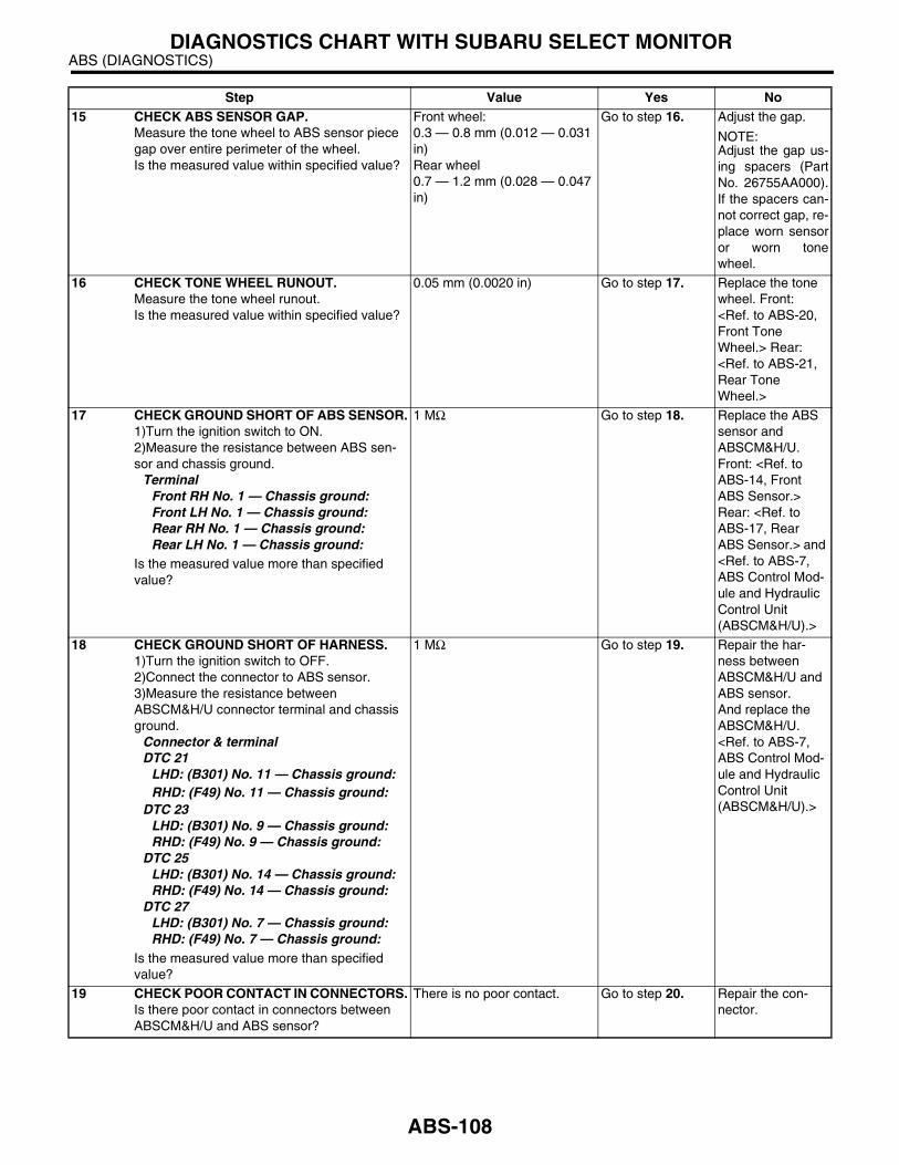
ABS (DIAGNOSTICS)DIAGNOSTICS CHART WITH SUBARU SELECT MONITOR
15 CHECK ABS SENSOR GAP.Measure the tone wheel to ABS sensor piece gap over entire perimeter of the wheel.Is the measured value within specified value?
Front wheel:0.3 — 0.8 mm (0.012 — 0.031 in)Rear wheel0.7 — 1.2 mm (0.028 — 0.047 in)
Go to step 16. Adjust the gap.
NOTE:Adjust the gap us-ing spacers (PartNo. 26755AA000).If the spacers can-not correct gap, re-place worn sensoror worn tonewheel.
16 CHECK TONE WHEEL RUNOUT.Measure the tone wheel runout.Is the measured value within specified value?
0.05 mm (0.0020 in) Go to step 17. Replace the tone wheel. Front: <Ref. to ABS-20, Front Tone Wheel.> Rear: <Ref. to ABS-21, Rear Tone Wheel.>
17 CHECK GROUND SHORT OF ABS SENSOR.1)Turn the ignition switch to ON.2)Measure the resistance between ABS sen-sor and chassis ground.
TerminalFront RH No. 1 — Chassis ground:Front LH No. 1 — Chassis ground:Rear RH No. 1 — Chassis ground:Rear LH No. 1 — Chassis ground:
Is the measured value more than specified value?
1 MΩ Go to step 18. Replace the ABS sensor and ABSCM&H/U. Front: <Ref. to ABS-14, Front ABS Sensor.> Rear: <Ref. to ABS-17, Rear ABS Sensor.> and <Ref. to ABS-7, ABS Control Mod-ule and Hydraulic Control Unit (ABSCM&H/U).>
18 CHECK GROUND SHORT OF HARNESS.1)Turn the ignition switch to OFF.2)Connect the connector to ABS sensor.3)Measure the resistance between ABSCM&H/U connector terminal and chassis ground.
Connector & terminalDTC 21
LHD: (B301) No. 11 — Chassis ground:RHD: (F49) No. 11 — Chassis ground:
DTC 23LHD: (B301) No. 9 — Chassis ground:RHD: (F49) No. 9 — Chassis ground:
DTC 25LHD: (B301) No. 14 — Chassis ground:RHD: (F49) No. 14 — Chassis ground:
DTC 27LHD: (B301) No. 7 — Chassis ground:RHD: (F49) No. 7 — Chassis ground:
Is the measured value more than specified value?
1 MΩ Go to step 19. Repair the har-ness between ABSCM&H/U and ABS sensor.And replace the ABSCM&H/U. <Ref. to ABS-7, ABS Control Mod-ule and Hydraulic Control Unit (ABSCM&H/U).>
19 CHECK POOR CONTACT IN CONNECTORS.Is there poor contact in connectors between ABSCM&H/U and ABS sensor?
There is no poor contact. Go to step 20. Repair the con-nector.
Step Value Yes No
ABS-108
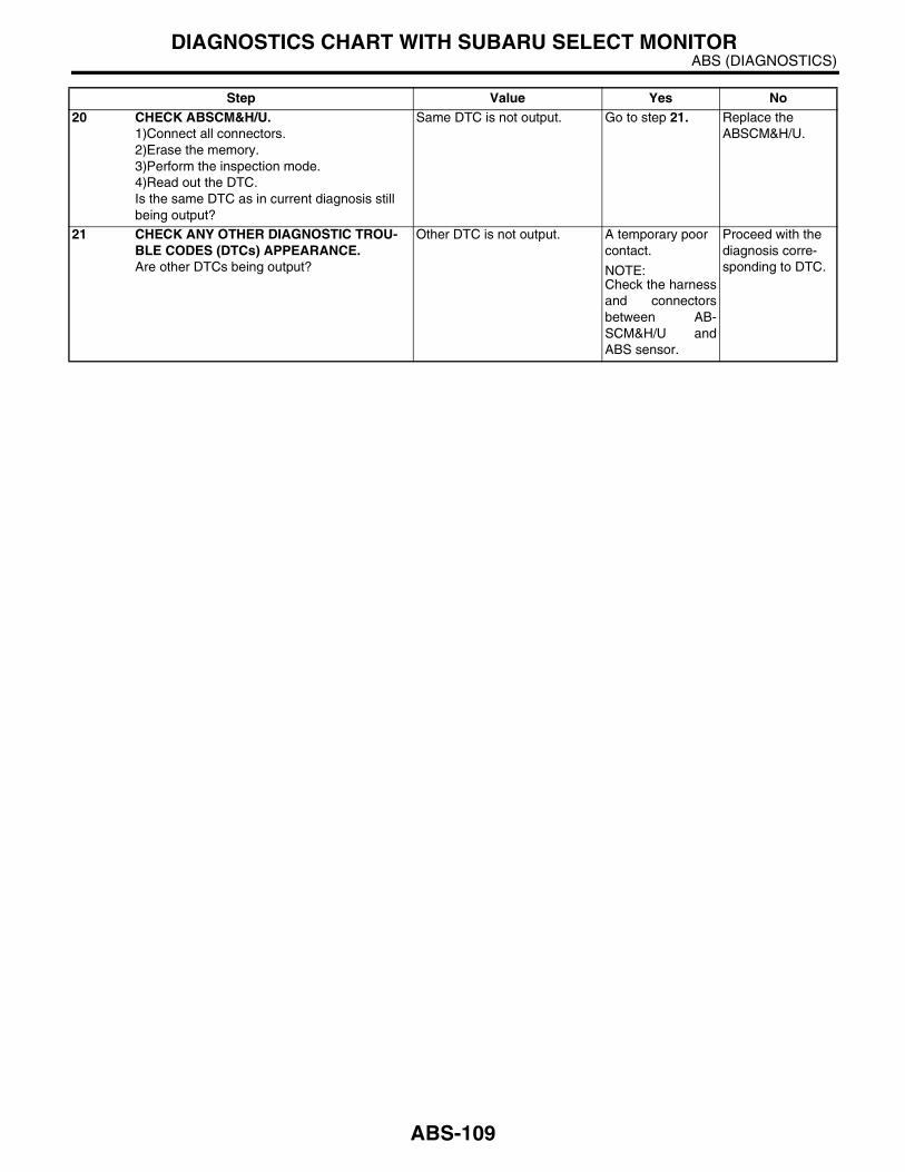
ABS (DIAGNOSTICS)DIAGNOSTICS CHART WITH SUBARU SELECT MONITOR
20 CHECK ABSCM&H/U.1)Connect all connectors.2)Erase the memory.3)Perform the inspection mode.4)Read out the DTC.Is the same DTC as in current diagnosis still being output?
Same DTC is not output. Go to step 21. Replace the ABSCM&H/U.
21 CHECK ANY OTHER DIAGNOSTIC TROU-BLE CODES (DTCs) APPEARANCE.Are other DTCs being output?
Other DTC is not output. A temporary poor contact.
NOTE:Check the harnessand connectorsbetween AB-SCM&H/U andABS sensor.
Proceed with the diagnosis corre-sponding to DTC.
Step Value Yes No
ABS-109

ABS (DIAGNOSTICS)DIAGNOSTICS CHART WITH SUBARU SELECT MONITOR
G: DTC 22 — FRONT RIGHT ABNORMAL ABS SENSOR SIGNAL —
NOTE:For the diagnostic procedure, refer to DTC 28. <Ref. to ABS-111, DTC 28 — REAR LEFT ABNORMAL ABSSENSOR SIGNAL —, Diagnostics Chart with Subaru Select Monitor.>
H: DTC 24 — FRONT LEFT ABNORMAL ABS SENSOR SIGNAL —
NOTE:For the diagnostic procedure, refer to DTC 28. <Ref. to ABS-111, DTC 28 — REAR LEFT ABNORMAL ABSSENSOR SIGNAL —, Diagnostics Chart with Subaru Select Monitor.>
I: DTC 26 — REAR RIGHT ABNORMAL ABS SENSOR SIGNAL —
NOTE:For the diagnostic procedure, refer to DTC 28. <Ref. to ABS-111, DTC 28 — REAR LEFT ABNORMAL ABSSENSOR SIGNAL —, Diagnostics Chart with Subaru Select Monitor.>
ABS-110
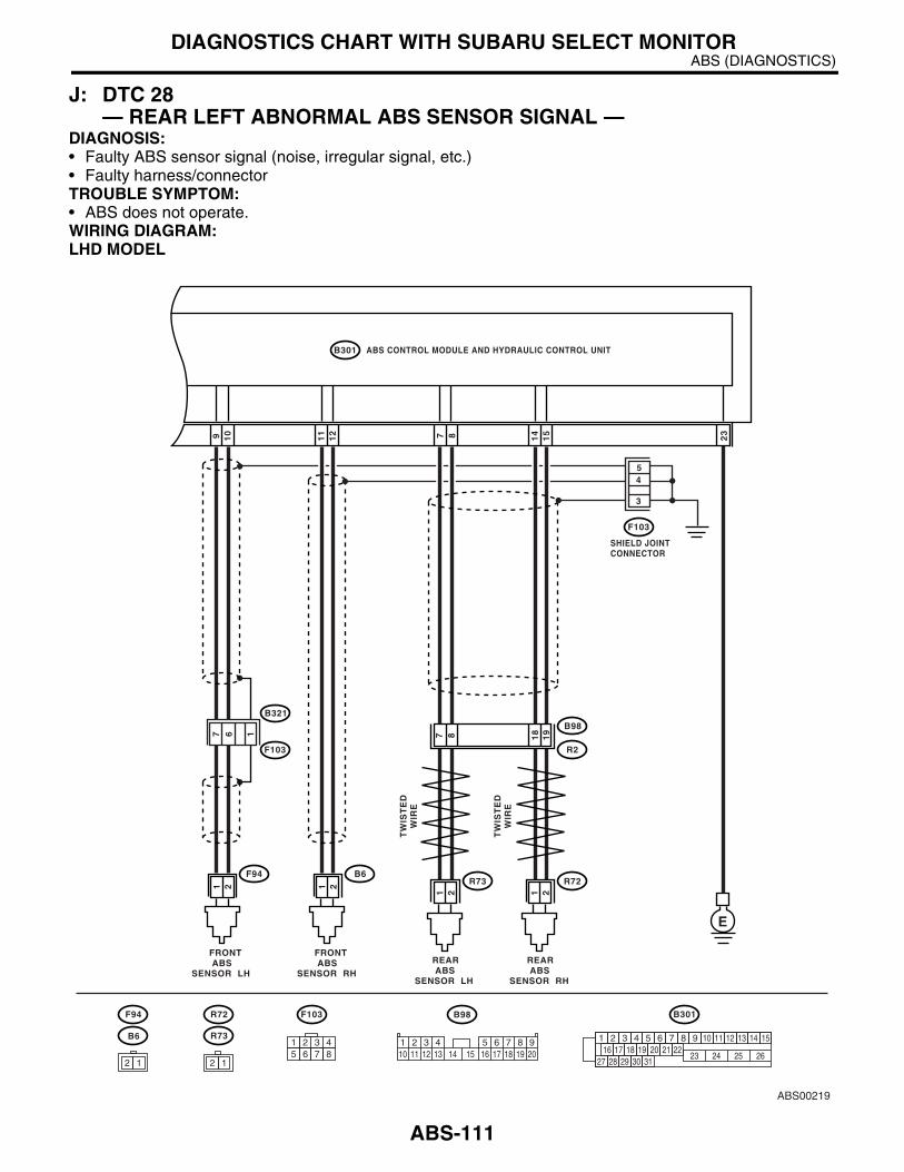
ABS (DIAGNOSTICS)DIAGNOSTICS CHART WITH SUBARU SELECT MONITOR
J: DTC 28 — REAR LEFT ABNORMAL ABS SENSOR SIGNAL —
DIAGNOSIS:• Faulty ABS sensor signal (noise, irregular signal, etc.)• Faulty harness/connectorTROUBLE SYMPTOM:• ABS does not operate.WIRING DIAGRAM:LHD MODEL
ABS00219
ABS CONTROL MODULE AND HYDRAULIC CONTROL UNIT
SHIELD JOINTCONNECTOR
B301
15
14
109 87 23
F103
REAR ABSSENSOR RH
B98
R72
R2
E
17 6
3
54
19
1887
REAR ABSSENSOR LH
R73
FRONT ABSSENSOR RH
B6
21
21
TW
IST
ED
WIR
E
TW
IST
ED
WIR
E
21
FRONT ABSSENSOR LH
F94
B321
F103
F103 B98
B6
F94 R72
R73
21
2 1
B301
1 2 3 4 5 6 7 8 9 10 11 12 13 14 1516 17 18 19 20 21 22
27 28 29 30 3123 24 25 26
12
11
1 2 3 4 5 6 7 8 910 11 12 13 14 15 16 17 18 19 20
1 2 3 45 6 7 8
2 1
ABS-111

ABS (DIAGNOSTICS)DIAGNOSTICS CHART WITH SUBARU SELECT MONITOR
RHD MODEL
ABS00224
ABS CONTROL MODULE AND HYDRAULIC CONTROL UNIT
SHIELD JOINTCONNECTOR
F49
15
14
109 87 23
F48
REAR ABSSENSOR RH
B98
R72
R2
E
12
29
28
26
25
REAR ABSSENSOR LH
R73
FRONT ABSSENSOR RH
F95
21
21
TW
IST
ED
WIR
E
TW
IST
ED
WIR
E
21
FRONT ABSSENSOR LH
F94
F62 B98F95F94 R72 R73
21
2 1
F49
1 2 3 4 5 6 7 8 9 10 11 12 13 14 1516 17 18 19 20 21 22
27 28 29 30 3123 24 25 26
12
11
1 2 3 4 5 6 7 8 910 11 12 13 14 15 16 17 18 19 20
1 2 3 45 6 7 8
2 1
10 11 12 13 14 15 16 17 181 2 3 4 7 85 69
F45
F45
B62
18
1787 15
38
ABS-112

ABS (DIAGNOSTICS)DIAGNOSTICS CHART WITH SUBARU SELECT MONITOR
Step Value Yes No1 CHECK OUTPUT OF ABS SENSOR USING
SELECT MONITOR.1)Select “Current data display & Save” on the select monitor.2)Read the ABS sensor output corresponding to faulty system in the select monitor data dis-play mode.Does the speed indicated on display change in response to speedometer reading during acceleration/deceleration when the steering wheel is in straight-ahead position?
Speed indicate on display changes.
Go to step 2. Go to step 8.
2 CHECK POOR CONTACT IN CONNECTORS.Turn the ignition switch to OFF.Is there poor contact in connectors between ABSCM&H/U and ABS sensor?
There is no poor contact. Go to step 3. Repair the con-nector.
3 CHECK SOURCES OF SIGNAL NOISE.Is the car telephone or wireless transmitter properly installed?
Correctly installed. Go to step 4. Properly install the car telephone or wireless transmit-ter.
4 CHECK SOURCES OF SIGNAL NOISE.Are noise sources (such as an antenna) installed near the sensor harness?
Not installed. Go to step 5. Install the noise sources apart from sensor harness.
5 CHECK SHIELD CIRCUIT.1)Turn the ignition switch to OFF.2)Connect all connectors.3)Measure the resistance between shield con-nector and chassis ground.
Connector & terminalDTC 22
LHD: (F103) No. 4 — Chassis ground:RHD: (F48) No. 2 — Chassis ground:
DTC 24LHD: (F103) No. 5 — Chassis ground:RHD: (F48) No. 1 — Chassis ground:
DTC 26LHD: (F103) No. 3 — Chassis ground:RHD: (F48) No. 3 — Chassis ground:
DTC 28LHD: (F103) No. 3 — Chassis ground:RHD: (F48) No. 3 — Chassis ground:
Is the measured value less than specified value?
0.5 Ω Go to step 6. Repair the shield harness.
6 CHECK ABSCM&H/U.1)Connect all connectors.2)Erase the memory.3)Perform the inspection mode.4)Read out the DTC.Is the same DTC as in the current diagnosis still being output?
Same DTC is not output. Go to step 7. Replace the ABSCM&H/U. <Ref. to ABS-7, ABS Control Mod-ule and Hydraulic Control Unit (ABSCM&H/U).>
7 CHECK ANY OTHER DIAGNOSTIC TROU-BLE CODES (DTCs) APPEARANCE.Are other DTCs being output?
Other DTC is not output. A temporary noise interference.
Proceed with the diagnosis corre-sponding to DTC.
8 CHECK INSTALLATION OF ABS SENSOR.Are the ABS sensor installation bolts tightened securely?
33 N·m (3.4 kgf-m, 24.6 ft-lb) Go to step 9. Tighten the ABS sensor installation bolts securely.
ABS-113

ABS (DIAGNOSTICS)DIAGNOSTICS CHART WITH SUBARU SELECT MONITOR
9 CHECK ABS SENSOR GAP.Measure the tone wheel to ABS sensor piece gap over entire perimeter of wheel.Is the measured value within specified value?
Front wheel:0.3 — 0.8 mm (0.012 — 0.031 in)Rear wheel0.7 — 1.2 mm (0.028 — 0.047 in)
Go to step 10. Adjust the gap.
NOTE:Adjust the gap us-ing spacer (PartNo. 26755AA000).If the spacers can-not correct gap, re-place worn sensoror worn tonewheel.
10 PREPARE OSCILLOSCOPE.Is an oscilloscope available?
Oscilloscope is available. Go to step 11. Go to step 12.
11 CHECK ABS SENSOR SIGNAL.1)Raise all four wheels off ground.2)Turn the ignition switch to OFF.3)Connect the oscilloscope to the connector.4)Turn the ignition switch to ON.5)Rotate the wheels and measure voltage at specified frequency. <Ref. to ABS-17, WAVE-FORM, Control Module I/O Signal.>
NOTE:When this inspection is completed, the ABSCM&H/U sometimes stores DTC 29 orDTC 56.
Connector 0& terminalDTC 22
LHD: (B6) No. 1 (+) — No. 2 (−−−−):RHD: (F95) No. 1 (+) — No. 2 (−−−−):
DTC 24LHD: (F94) No. 1 (+) — No. 2 (−−−−):RHD: (F94) No. 1 (+) — No. 2 (−−−−):
DTC 26LHD: (B98) No. 18 (+) — No. 19 (−−−−):RHD: (B98) No. 28 (+) — No. 29 (−−−−):
DTC 28LHD: (B98) No. 7 (+) — No. 8 (−−−−):RHD: (B98) No. 25 (+) — No. 26 (−−−−):
Is the measured value as same as specified value?
Oscilloscope pattern is smooth, as shown in the figure.
Go to step 15. Go to step 12.
12 CHECK CONTAMINATION OF ABS SENSOR OR TONE WHEEL.Remove the disc rotor or drum from hub in accordance with DTC.Is the ABS sensor piece or tone wheel contam-inated by dirt or other foreign matter?
ABS sensor piece or tone wheel is not contaminated.
Go to step 13. Thoroughly remove dirt or other foreign mat-ter.
13 CHECK DAMAGE OF ABS SENSOR OR TONE WHEEL.Are there broken or damaged in the ABS sen-sor piece or tone wheel?
There are no broken or dam-aged in the ABS sensor piece or tone wheel.
Go to step 14. Replace the ABS sensor or tone wheel. Front: <Ref. to ABS-14, Front ABS Sen-sor.> Rear: <Ref. to ABS-17, Rear ABS Sensor.> and Front: <Ref. to ABS-20, Front Tone Wheel.> Rear: <Ref. to ABS-21, Rear Tone Wheel.>
Step Value Yes No
ABS-114

ABS (DIAGNOSTICS)DIAGNOSTICS CHART WITH SUBARU SELECT MONITOR
14 CHECK TONE WHEEL RUNOUT.Measure the tone wheel runout.Is the measured value less than specified value?
0.05 mm (0.0020 in) Go to step 15. Replace the tone wheel. Front: <Ref. to ABS-20, Front Tone Wheel.> Rear: <Ref. to ABS-21, Rear Tone Wheel.>
15 CHECK RESISTANCE OF ABS SENSOR.1)Turn the ignition switch to OFF.2)Disconnect the connector from ABS sensor.3)Measure the resistance between ABS sen-sor connector terminals while shaking the har-ness lightly.
TerminalFront RH No. 1 — No. 2:Front LH No. 1 — No. 2:Rear RH No. 1 — No. 2:Rear LH No. 1 — No. 2:
Is the measured value within specified value?
Front: 1 — 1.5 kΩRear: 1.025 — 1.265 kΩ
Go to step 16. Replace the ABS sensor. Front: <Ref. to ABS-14, Front ABS Sen-sor.> Rear: <Ref. to ABS-17, Rear ABS Sensor.>
16 CHECK GROUND SHORT OF ABS SENSOR.Measure the resistance between ABS sensor and chassis ground.
TerminalFront RH No. 1 — Chassis ground:Front LH No. 1 — Chassis ground:Rear RH No. 1 — Chassis ground:Rear LH No. 1 — Chassis ground:
Is the measured value more than specified value?
1 MΩ Go to step 17. Replace the ABS sensor. Front: <Ref. to ABS-14, Front ABS Sen-sor.> Rear: <Ref. to ABS-17, Rear ABS Sensor.>
17 CHECK HARNESS/CONNECTOR BETWEEN ABSCM&H/U AND ABS SENSOR.1)Connect the connector to ABS sensor.2)Disconnect the connector from ABSCM&H/U.3)Measure the resistance at ABSCM&H/U connector terminals.
Connector & terminalDTC 22
LHD: (B301) No. 11 — No. 12:RHD: (F49) No. 11 — No. 12:
DTC 24LHD: (B301) No. 9 — No. 10:RHD: (F49) No. 9 — No. 10:
DTC 26LHD: (B301) No. 14 — No. 15:RHD: (F49) No. 14 — No. 15:
DTC 28LHD: (B301) No. 7 — No. 8:RHD: (F49) No. 7 — No. 8:
Is the measured value within specified value?
Front: 1 — 1.5 kΩRear: 1.025 — 1.265 kΩ
Go to step 18. Repair the har-ness/connector between ABSCM&H/U and ABS sensor.
Step Value Yes No
ABS-115

ABS (DIAGNOSTICS)DIAGNOSTICS CHART WITH SUBARU SELECT MONITOR
18 CHECK GROUND SHORT OF HARNESS.Measure the resistance between ABSCM&H/U connector and chassis ground.
Connector & terminalDTC 22
LHD: (B301) No. 11 — Chassis ground:RHD: (F49) No. 11 — Chassis ground:
DTC 24LHD: (B301) No. 9 — Chassis ground:RHD: (F49) No. 9 — Chassis ground:
DTC 26LHD: (B301) No. 14 — Chassis ground:RHD: (F49) No. 14 — Chassis ground:
DTC 28LHD: (B301) No. 7 — Chassis ground:RHD: (F49) No. 7 — Chassis ground:
Is the measured value more than specified value?
1 MΩ Go to step 19. Repair the har-ness/connector between ABSCM&H/U and ABS sensor.
19 CHECK GROUND CIRCUIT OF ABSCM&H/U.Measure the resistance between ABSCM&H/U and chassis ground.
Connector & terminalLHD: (B301) No. 23 — Chassis ground:RHD: (F49) No. 23 — Chassis ground:
Is the measured value less than specified value?
0.5 Ω Go to step 20. Repair the ABSCM&H/U ground harness.
20 CHECK POOR CONTACT IN CONNECTORS.Is there poor contact in connectors between ABSCM&H/U and ABS sensor?
There is no poor contact. Go to step 21. Repair the con-nector.
21 CHECK SOURCES OF SIGNAL NOISE.Is the car telephone or the wireless transmitter properly installed?
Correctly installed. Go to step 22. Properly install the car telephone or wireless transmit-ter.
22 CHECK SOURCES OF SIGNAL NOISE.Are noise sources (such as an antenna) installed near the sensor harness?
Not installed Go to step 23. Install the noise sources apart from sensor harness.
23 CHECK SHIELD CIRCUIT.1)Connect all connectors.2)Measure the resistance between shield con-nector and chassis ground.
Connector & terminalDTC 22
LHD: (F103) No. 4 — Chassis ground:RHD: (F48) No. 2 — Chassis ground:
DTC 24LHD: (F103) No. 5 — Chassis ground:RHD: (F48) No. 1 — Chassis ground:
DTC 26LHD: (F103) No. 3 — Chassis ground:RHD: (F48) No. 3 — Chassis ground:
DTC 28LHD: (F103) No. 3 — Chassis ground:RHD: (F48) No. 3 — Chassis ground:
Is the measured value less than specified value?
0.5 Ω Go to step 24. Repair the shield harness.
Step Value Yes No
ABS-116

ABS (DIAGNOSTICS)DIAGNOSTICS CHART WITH SUBARU SELECT MONITOR
24 CHECK ABSCM&H/U.1)Connect all connectors.2)Erase the memory.3)Perform the inspection mode.4)Read out the DTC.Is the same DTC as in the current diagnosis still being output?
Same DTC is not output. Go to step 25. Replace the ABSCM&H/U. <Ref. to ABS-7, ABS Control Mod-ule and Hydraulic Control Unit (ABSCM&H/U).>
25 CHECK ANY OTHER DIAGNOSTIC TROU-BLE CODES (DTCs) APPEARANCE.Are other DTCs being output?
Other DTC is not output. A temporary noise interference.
NOTE:Although the ABSwarning light re-mains illuminatingat this point, this isa normal condition.Vehicle must bedriven at approx.12 km/h (7.46MPH) or faster toturn off ABS warn-ing light. Makesure that the ABSwarning light goesoff after driving ve-hicle.
Proceed with the diagnosis corre-sponding to DTC.
Step Value Yes No
ABS-117
ABS (DIAGNOSTICS)DIAGNOSTICS CHART WITH SUBARU SELECT MONITOR
K: DTC 29 — ABNORMAL ABS SENSOR SIGNAL ON ANY ONE OF FOUR SENSOR —
DIAGNOSIS:• Faulty ABS sensor signal (noise, irregular signal, etc.)• Faulty tone wheel• Wheels turning freely for a long timeTROUBLE SYMPTOM:• ABS does not operate.• EBD does not operate.
NOTE:In addition to the ABS warning light, brake warning light illuminates.
ABS-118

ABS (DIAGNOSTICS)DIAGNOSTICS CHART WITH SUBARU SELECT MONITOR
WIRING DIAGRAM:LHD MODEL
ABS00219
ABS CONTROL MODULE AND HYDRAULIC CONTROL UNIT
SHIELD JOINTCONNECTOR
B301
15
14
109 87 23
F103
REAR ABSSENSOR RH
B98
R72
R2
E
17 6
3
54
19
1887
REAR ABSSENSOR LH
R73
FRONT ABSSENSOR RH
B6
21
21
TW
IST
ED
WIR
E
TW
IST
ED
WIR
E
21
FRONT ABSSENSOR LH
F94
B321
F103
F103 B98
B6
F94 R72
R73
21
2 1
B301
1 2 3 4 5 6 7 8 9 10 11 12 13 14 1516 17 18 19 20 21 22
27 28 29 30 3123 24 25 26
12
11
1 2 3 4 5 6 7 8 910 11 12 13 14 15 16 17 18 19 20
1 2 3 45 6 7 8
2 1
ABS-119
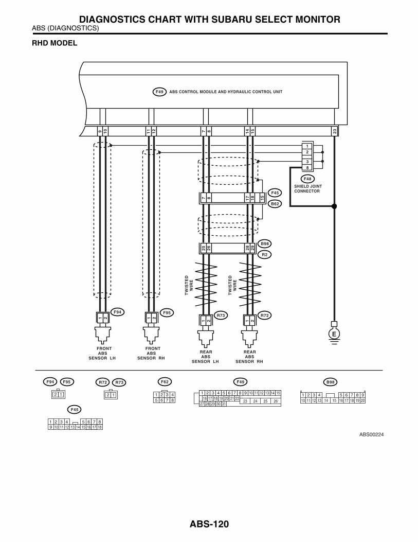
ABS (DIAGNOSTICS)DIAGNOSTICS CHART WITH SUBARU SELECT MONITOR
RHD MODEL
ABS00224
ABS CONTROL MODULE AND HYDRAULIC CONTROL UNIT
SHIELD JOINTCONNECTOR
F49
15
14
109 87 23
F48
REAR ABSSENSOR RH
B98
R72
R2
E
12
29
28
26
25
REAR ABSSENSOR LH
R73
FRONT ABSSENSOR RH
F95
21
21
TW
IST
ED
WIR
E
TW
IST
ED
WIR
E
21
FRONT ABSSENSOR LH
F94
F62 B98F95F94 R72 R73
21
2 1
F49
1 2 3 4 5 6 7 8 9 10 11 12 13 14 1516 17 18 19 20 21 22
27 28 29 30 3123 24 25 26
12
11
1 2 3 4 5 6 7 8 910 11 12 13 14 15 16 17 18 19 20
1 2 3 45 6 7 8
2 1
10 11 12 13 14 15 16 17 181 2 3 4 7 85 69
F45
F45
B62
18
1787 15
38
ABS-120

ABS (DIAGNOSTICS)DIAGNOSTICS CHART WITH SUBARU SELECT MONITOR
Step Value Yes No1 CHECK IF THE WHEELS HAVE TURNED
FREELY FOR A LONG TIME.Check if the wheels have been turned freely for more than one minute, such as when vehicle is jacked-up, under full-lock cornering or when tire is not in contact with road surface.
Wheels have not been turned freely.
Go to step 2. The ABS is nor-mal. Erase the DTC.
NOTE:When the wheelsturn freely for along time, such aswhen vehicle istowed or jacked-up, or when steer-ing wheel is contin-uously turned allway, this troublecode may some-times occur.
2 CHECK TIRE SPECIFICATIONS.Turn the ignition switch to OFF.Are the tire specifications correct?
Tire specifications are correct. Go to step 3. Replace the tire.
3 CHECK WEAR OF TIRE.Is the tire worn excessively?
Tire is not worn excessively. Go to step 4. Replace the tire.
4 CHECK TIRE PRESSURE.Is the tire pressure correct?
Tire pressure is correct. Go to step 5. Adjust the tire pressure.
5 CHECK INSTALLATION OF ABS SENSOR.Are the ABS sensor installation bolts tightened securely?
33 N·m (3.4 kgf-m, 24.6 ft-lb) Go to step 6. Tighten the ABS sensor installation bolts securely.
6 CHECK ABS SENSOR GAP.Measure the tone wheel to ABS sensor piece gap over entire perimeter of the wheel.Is the measured value within specified value?
Front wheel:0.3 — 0.8 mm (0.012 — 0.031 in)Rear wheel0.7 — 1.2 mm (0.028 — 0.047 in)
Go to step 7. Adjust the gap.
NOTE:Adjust the gap us-ing spacer (PartNo. 26755AA000).If the spacers can-not correct gap, re-place worn sensoror worn tonewheel.
7 PREPARE OSCILLOSCOPE.Is an oscilloscope available?
Oscilloscope is available. Go to step 8. Go to step 9.
ABS-121
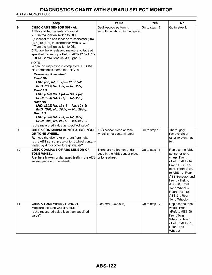
ABS (DIAGNOSTICS)DIAGNOSTICS CHART WITH SUBARU SELECT MONITOR
8 CHECK ABS SENSOR SIGNAL.1)Raise all four wheels off ground.2)Turn the ignition switch to OFF.3)Connect the oscilloscope to connector (B6), (B99) or (F94) in accordance with DTC.4)Turn the ignition switch to ON.5)Rotate the wheels and measure voltage at specified frequency. <Ref. to ABS-17, WAVE-FORM, Control Module I/O Signal.>
NOTE:When this inspection is completed, ABSCM&H/U sometimes stores the DTC 29.
Connector & terminalFront RH
LHD: (B6) No. 1 (+) — No. 2 (−−−−):RHD: (F95) No. 1 (+) — No. 2 (−−−−):
Front LHLHD: (F94) No. 1 (+) — No. 2 (−−−−):RHD: (F94) No. 1 (+) — No. 2 (−−−−):
Rear RHLHD: (B98) No. 18 (+) — No. 19 (−−−−):RHD: (B98) No. 28 (+) — No. 29 (−−−−):
Rear LHLHD: (B98) No. 7 (+) — No. 8 (−−−−):RHD: (B98) No. 25 (+) — No. 26 (−−−−):
Is the measured value as specified value?
Oscilloscope pattern is smooth, as shown in the figure.
Go to step 12. Go to step 9.
9 CHECK CONTAMINATION OF ABS SENSOR OR TONE WHEEL.Remove the disc rotor or drum from hub.Is the ABS sensor piece or tone wheel contam-inated by dirt or other foreign matter?
ABS sensor piece or tone wheel is not contaminated.
Go to step 10. Thoroughly remove dirt or other foreign mat-ter.
10 CHECK DAMAGE OF ABS SENSOR OR TONE WHEEL.Are there broken or damaged teeth in the ABS sensor piece or tone wheel?
There are no broken or dam-aged in the ABS sensor piece or tone wheel.
Go to step 11. Replace the ABS sensor or tone wheel. Front: <Ref. to ABS-14, Front ABS Sen-sor.> Rear: <Ref. to ABS-17, Rear ABS Sensor.> and Front: <Ref. to ABS-20, Front Tone Wheel.> Rear: <Ref. to ABS-21, Rear Tone Wheel.>
11 CHECK TONE WHEEL RUNOUT.Measure the tone wheel runout.Is the measured value less than specified value?
0.05 mm (0.0020 in) Go to step 12. Replace the tone wheel. Front: <Ref. to ABS-20, Front Tone Wheel.> Rear: <Ref. to ABS-21, Rear Tone Wheel.>
Step Value Yes No
ABS-122
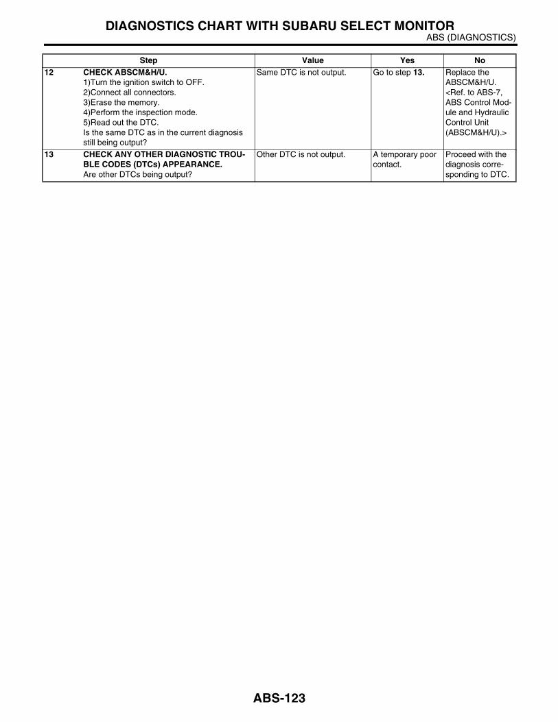
ABS (DIAGNOSTICS)DIAGNOSTICS CHART WITH SUBARU SELECT MONITOR
12 CHECK ABSCM&H/U.1)Turn the ignition switch to OFF.2)Connect all connectors.3)Erase the memory.4)Perform the inspection mode.5)Read out the DTC.Is the same DTC as in the current diagnosis still being output?
Same DTC is not output. Go to step 13. Replace the ABSCM&H/U. <Ref. to ABS-7, ABS Control Mod-ule and Hydraulic Control Unit (ABSCM&H/U).>
13 CHECK ANY OTHER DIAGNOSTIC TROU-BLE CODES (DTCs) APPEARANCE.Are other DTCs being output?
Other DTC is not output. A temporary poor contact.
Proceed with the diagnosis corre-sponding to DTC.
Step Value Yes No
ABS-123

ABS (DIAGNOSTICS)DIAGNOSTICS CHART WITH SUBARU SELECT MONITOR
L: DTC 31 — FRONT RIGHT INLET VALVE MALFUNCTION —
NOTE:For the diagnostic procedure, refer to DTC 37. <Ref. to ABS-125, DTC 37 — REAR LEFT INLET VALVEMALFUNCTION —, Diagnostics Chart with Subaru Select Monitor.>
M: DTC 33 — FRONT LEFT INLET VALVE MALFUNCTION —
NOTE:For the diagnostic procedure, refer to DTC 37. <Ref. to ABS-125, DTC 37 — REAR LEFT INLET VALVEMALFUNCTION —, Diagnostics Chart with Subaru Select Monitor.>
N: DTC 35 — REAR RIGHT INLET VALVE MALFUNCTION —
NOTE:For the diagnostic procedure, refer to DTC 37. <Ref. to ABS-125, DTC 37 — REAR LEFT INLET VALVEMALFUNCTION —, Diagnostics Chart with Subaru Select Monitor.>
ABS-124

ABS (DIAGNOSTICS)DIAGNOSTICS CHART WITH SUBARU SELECT MONITOR
O: DTC 37 — REAR LEFT INLET VALVE MALFUNCTION —
DIAGNOSIS:• Faulty harness/connector• Faulty inlet solenoid valveTROUBLE SYMPTOM:• ABS does not operate.• EBD does not operate.
NOTE:In addition to the ABS warning light, brake warning light illuminates.
ABS-125

ABS (DIAGNOSTICS)DIAGNOSTICS CHART WITH SUBARU SELECT MONITOR
WIRING DIAGRAM:
ABS00229
ABS CONTROL MODULE AND HYDRAULIC CONTROL UNIT
1 2 3 4 5 6 7 8 9 10 11 12 13 14 1516 17 18 19 20 21 22
27 28 29 30 3123 24 25 26
BATTERY
SB
F-1
SB
F-4
No
.18
GENERATOR
E
E
231
IGNITIONSWITCH
B301
: LHD MODEL
: RHD MODEL
LHD
RHD
F49
LHD
RHD
:
:
B301
F49
LHD
RHD
:
:
ABS-126

ABS (DIAGNOSTICS)DIAGNOSTICS CHART WITH SUBARU SELECT MONITOR
Step Value Yes No1 CHECK INPUT VOLTAGE OF ABSCM&H/U.
1)Turn the ignition switch to OFF.2)Disconnect the connector from ABSCM&H/U.3)Run the engine at idle.4)Measure the voltage between ABSCM&H/U connector and chassis ground.
Connector & terminalLHD: (B301) No. 1 (+) — Chassis ground (−−−−):RHD: (F49) No. 1 (+) — Chassis ground (−−−−):
Is the measured value within specified value?
10 — 15 V Go to step 2. Repair the har-ness connector between battery, ignition switch and ABSCM&H/U.
2 CHECK GROUND CIRCUIT OF ABSCM&H/U.1)Turn the ignition switch to OFF.2)Measure the resistance between ABSCM&H/U connector and chassis ground.
Connector & terminalLHD: (B301) No. 23 — Chassis ground:RHD: (F49) No. 23 — Chassis ground:
Is the measured value less than specified value?
0.5 Ω Go to step 3. Repair the ABSCM&H/U ground harness.
3 CHECK POOR CONTACT IN CONNECTORS.Is there poor contact in connectors between generator, battery and ABSCM&H/U?
There is no poor contact. Go to step 4. Repair the con-nector.
4 CHECK ABSCM&H/U.1)Connect all connectors.2)Erase the memory.3)Perform the inspection mode.4)Read out the DTC.Is the same DTC as in the current diagnosis still being output?
Same DTC is not output. Go to step 5. Replace the ABSCM&H/U. <Ref. to ABS-7, ABS Control Mod-ule and Hydraulic Control Unit (ABSCM&H/U).>
5 CHECK ANY OTHER DIAGNOSTIC TROU-BLE CODES (DTCs) APPEARANCE.Are other DTCs being output?
Other DTC is not output. A temporary poor contact.
Proceed with the diagnosis corre-sponding to DTC.
ABS-127
ABS (DIAGNOSTICS)DIAGNOSTICS CHART WITH SUBARU SELECT MONITOR
P: DTC 32 — FRONT RIGHT OUTLET VALVE MALFUNCTION —
NOTE:For the diagnostic procedure, refer to DTC 38. <Ref. to ABS-129, DTC 38 — REAR LEFT OUTLET VALVEMALFUNCTION —, Diagnostics Chart with Subaru Select Monitor.>
Q: DTC 34 — FRONT LEFT OUTLET VALVE MALFUNCTION —
NOTE:For the diagnostic procedure, refer to DTC 38. <Ref. to ABS-129, DTC 38 — REAR LEFT OUTLET VALVEMALFUNCTION —, Diagnostics Chart with Subaru Select Monitor.>
R: DTC 36 — REAR RIGHT OUTLET VALVE MALFUNCTION —
NOTE:For the diagnostic procedure, refer to DTC 38. <Ref. to ABS-129, DTC 38 — REAR LEFT OUTLET VALVEMALFUNCTION —, Diagnostics Chart with Subaru Select Monitor.>
ABS-128

ABS (DIAGNOSTICS)DIAGNOSTICS CHART WITH SUBARU SELECT MONITOR
S: DTC 38 — REAR LEFT OUTLET VALVE MALFUNCTION —
DIAGNOSIS:• Faulty harness/connector• Faulty outlet solenoid valveTROUBLE SYMPTOM:• ABS does not operate.• EBD does not operate.
NOTE:In addition to the ABS warning light, brake warning light illuminates.
ABS-129
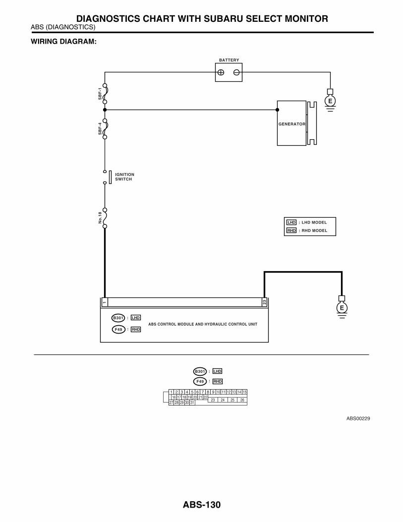
ABS (DIAGNOSTICS)DIAGNOSTICS CHART WITH SUBARU SELECT MONITOR
WIRING DIAGRAM:
ABS00229
ABS CONTROL MODULE AND HYDRAULIC CONTROL UNIT
1 2 3 4 5 6 7 8 9 10 11 12 13 14 1516 17 18 19 20 21 22
27 28 29 30 3123 24 25 26
BATTERY
SB
F-1
SB
F-4
No
.18
GENERATOR
E
E
231
IGNITIONSWITCH
B301
: LHD MODEL
: RHD MODEL
LHD
RHD
F49
LHD
RHD
:
:
B301
F49
LHD
RHD
:
:
ABS-130

ABS (DIAGNOSTICS)DIAGNOSTICS CHART WITH SUBARU SELECT MONITOR
Step Value Yes No1 CHECK INPUT VOLTAGE OF ABSCM&H/U.
1)Turn the ignition switch to OFF.2)Disconnect the connector from ABSCM&H/U.3)Run the engine at idle.4)Measure the voltage between ABSCM&H/U connector and chassis ground.
Connector & terminalLHD: (B301) No. 1 (+) — Chassis ground (−−−−):RHD: (F49) No. 1 (+) — Chassis ground (−−−−):
Is the measured value within specified value?
10 — 15 V Go to step 2. Repair the har-ness connector between battery, ignition switch and ABSCM&H/U.
2 CHECK GROUND CIRCUIT OF ABSCM&H/U.1)Turn the ignition switch to OFF.2)Measure the resistance between ABSCM&H/U connector and chassis ground.
Connector & terminalLHD: (B301) No. 23 — Chassis ground:RHD: (F49) No. 23 — Chassis ground:
Is the measured value less than specified value?
0.5 Ω Go to step 3. Repair the ABSCM&H/U ground harness.
3 CHECK POOR CONTACT IN CONNECTORS.Is there poor contact in connectors between generator, battery and ABSCM&H/U?
There is no poor contact. Go to step 4. Repair the con-nector.
4 CHECK ABSCM&H/U.1)Connect all connectors.2)Erase the memory.3)Perform the inspection mode.4)Read out the DTC.Is the same DTC as in the current diagnosis still being output?
Same DTC is not output. Go to step 5. Replace the ABSCM&H/U. <Ref. to ABS-7, ABS Control Mod-ule and Hydraulic Control Unit (ABSCM&H/U).>
5 CHECK ANY OTHER DIAGNOSTIC TROU-BLE CODES (DTCs) APPEARANCE.Are other DTCs being output?
Other DTC is not output. A temporary poor contact.
Proceed with the diagnosis corre-sponding to DTC.
ABS-131

ABS (DIAGNOSTICS)DIAGNOSTICS CHART WITH SUBARU SELECT MONITOR
T: DTC 41 — ABS CONTROL MODULE MALFUNCTION —
DIAGNOSIS:• Faulty ABSCM&H/UTROUBLE SYMPTOM:• ABS does not operate.• EBD does not operate.
NOTE:In addition to the ABS warning light, brake warning light illuminates.WIRING DIAGRAM:
ABS00234
E
ABS CONTROL MODULE ANDHYDRAULIC CONTROL UNIT
23
1 2 3 4 5 6 7 8 9 10 11 12 13 14 1516 17 18 19 20 21 22
27 28 29 30 3123 24 25 26
: LHD MODEL
: RHD MODEL
LHD
RHD
B301
F49
LHD
RHD
:
:
B301
F49
LHD
RHD
:
:
ABS-132

ABS (DIAGNOSTICS)DIAGNOSTICS CHART WITH SUBARU SELECT MONITOR
Step Value Yes No1 CHECK GROUND CIRCUIT OF ABSCM&H/U.
1)Turn the ignition switch to OFF.2)Disconnect the connector from ABSCM&H/U.3)Measure the resistance between ABSCM&H/U and chassis ground.
Connector & terminalLHD: (B301) No. 23 — Chassis ground:RHD: (F49) No. 23 — Chassis ground:
Is the measured value less than specified value?
0.5 Ω Go to step 2. Repair the ABSCM&H/U ground harness.
2 CHECK POOR CONTACT IN CONNECTORS.Is there poor contact in connectors between battery, ignition switch and ABSCM&H/U?
There is no poor contact. Go to step 3. Repair the con-nector.
3 CHECK SOURCES OF SIGNAL NOISE.Is the car telephone or wireless transmitter properly installed?
Correctly installed. Go to step 4. Properly install the car telephone or wireless transmit-ter.
4 CHECK SOURCES OF SIGNAL NOISE.Are noise sources (such as an antenna) installed near the sensor harness?
Not installed. Go to step 5. Install the noise sources apart from sensor harness.
5 CHECK ABSCM&H/U.1)Turn the ignition switch to OFF.2)Connect all connectors.3)Erase the memory.4)Perform the inspection mode.5)Read out the DTC.Is the same DTC as in current diagnosis still being output?
Same DTC is not output. Go to step 6. Replace the ABSCM&H/U. <Ref. to ABS-7, ABS Control Mod-ule and Hydraulic Control Unit (ABSCM&H/U).>
6 CHECK ANY OTHER DIAGNOSTIC TROU-BLE CODES (DTCs) APPEARANCE.Are other DTCs being output?
Other DTC is not output. A temporary poor contact.
Proceed with the diagnosis corre-sponding to DTC.
ABS-133
ABS (DIAGNOSTICS)DIAGNOSTICS CHART WITH SUBARU SELECT MONITOR
U: DTC 42 — POWER SUPPLY VOLTAGE TOO LOW —
DIAGNOSIS:• Power source voltage of the ABSCM&H/U is low.TROUBLE SYMPTOM:• ABS does not operate.• EBD does not operate.
NOTE:In addition to the ABS warning light, brake warning light illuminates temporarily. Both warning lights go off onthe recovery of voltage.
ABS-134

ABS (DIAGNOSTICS)DIAGNOSTICS CHART WITH SUBARU SELECT MONITOR
WIRING DIAGRAM:
ABS00229
ABS CONTROL MODULE AND HYDRAULIC CONTROL UNIT
1 2 3 4 5 6 7 8 9 10 11 12 13 14 1516 17 18 19 20 21 22
27 28 29 30 3123 24 25 26
BATTERY
SB
F-1
SB
F-4
No
.18
GENERATOR
E
E
231
IGNITIONSWITCH
B301
: LHD MODEL
: RHD MODEL
LHD
RHD
F49
LHD
RHD
:
:
B301
F49
LHD
RHD
:
:
ABS-135
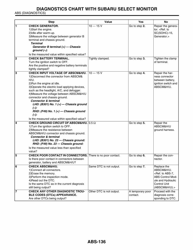
ABS (DIAGNOSTICS)DIAGNOSTICS CHART WITH SUBARU SELECT MONITOR
Step Value Yes No1 CHECK GENERATOR.
1)Start the engine.2)Idle after warm-up.3)Measure the voltage between generator B terminal and chassis ground.
TerminalGenerator B terminal (+) — Chassis ground (−−−−):
Is the measured value within specified value?
10 — 15 V Go to step 2. Repair the genera-tor. <Ref. to SC(SOHC)-15, Generator.>
2 CHECK BATTERY TERMINAL.Turn the ignition switch to OFF.Are the positive and negative battery terminals tightly clamped?
Tightly clamped. Go to step 3. Tighten the clamp of terminal.
3 CHECK INPUT VOLTAGE OF ABSCM&H/U.1)Disconnect the connector from ABSCM&H/U.2)Run the engine at idle.3)Operate the electric load applying devices, such as the headlight, A/C, and defogger.4)Measure the voltage between ABSCM&H/U connector and chassis ground.
Connector & terminalLHD: (B301) No. 1 (+) — Chassis ground (−−−−):RHD: (F49) No. 1 (+) — Chassis ground (−−−−):
Is the measured value within specified value?
10 — 15 V Go to step 4. Repair the har-ness connector between battery, ignition switch and ABSCM&H/U.
4 CHECK GROUND CIRCUIT OF ABSCM&H/U.1)Turn the ignition switch to OFF.2)Measure the resistance between ABSCM&H/U connector and chassis ground.
Connector & terminalLHD: (B301) No. 23 — Chassis ground:RHD: (F49) No. 23 — Chassis ground:
Is the measured value less than specified value?
0.5 Ω Go to step 5. Repair the ABSCM&H/U ground harness.
5 CHECK POOR CONTACT IN CONNECTORS.Is there poor contact in connectors between generator, battery and ABSCM&H/U?
There is no poor contact. Go to step 6. Repair the con-nector.
6 CHECK ABSCM&H/U.1)Connect all connectors.2)Erase the memory.3)Perform the inspection mode.4)Read out the DTC.Is the same DTC as in the current diagnosis still being output?
Same DTC is not output. Go to step 7. Replace the ABSCM&H/U. <Ref. to ABS-7, ABS Control Mod-ule and Hydraulic Control Unit (ABSCM&H/U).>
7 CHECK ANY OTHER DIAGNOSTIC TROU-BLE CODES (DTCs) APPEARANCE.Are other DTCs being output?
Other DTC is not output. A temporary poor contact.
Proceed with the diagnosis corre-sponding to DTC.
ABS-136

ABS (DIAGNOSTICS)DIAGNOSTICS CHART WITH SUBARU SELECT MONITOR
V: DTC 42 — POWER SUPPLY VOLTAGE TOO HIGH —
DIAGNOSIS:• Power source voltage of the ABSCM&H/U is high.TROUBLE SYMPTOM:• ABS does not operate.• EBD does not operate.
NOTE:In addition to the ABS warning light, brake warning light illuminates temporarily. Both warning lights go off onthe recovery of voltage.
ABS-137

ABS (DIAGNOSTICS)DIAGNOSTICS CHART WITH SUBARU SELECT MONITOR
WIRING DIAGRAM:
ABS00229
ABS CONTROL MODULE AND HYDRAULIC CONTROL UNIT
1 2 3 4 5 6 7 8 9 10 11 12 13 14 1516 17 18 19 20 21 22
27 28 29 30 3123 24 25 26
BATTERY
SB
F-1
SB
F-4
No
.18
GENERATOR
E
E
231
IGNITIONSWITCH
B301
: LHD MODEL
: RHD MODEL
LHD
RHD
F49
LHD
RHD
:
:
B301
F49
LHD
RHD
:
:
ABS-138

ABS (DIAGNOSTICS)DIAGNOSTICS CHART WITH SUBARU SELECT MONITOR
Step Value Yes No1 CHECK GENERATOR.
1)Start the engine.2)Idle after warm-up.3)Measure the voltage between generator B terminal and chassis ground.
TerminalGenerator B terminal (+) — Chassis ground (−−−−):
Is the measured value within specified value?
10 — 17 V Go to step 2. Repair the genera-tor. <Ref. to SC(SOHC)-15, Generator.>
2 CHECK BATTERY TERMINAL.Turn the ignition switch to OFF.Are the positive and negative battery terminals tightly clamped?
Tightly clamped. Go to step 3. Tighten the clamp of terminal.
3 CHECK INPUT VOLTAGE OF ABSCM&H/U.1)Disconnect the connector from ABSCM&H/U.2)Run the engine at idle.3)Operate the electric load applying devices, such as the headlight, A/C, and defogger.4)Measure the voltage between ABSCM&H/U connector and chassis ground.
Connector & terminalLHD: (B301) No. 1 (+) — Chassis ground (−−−−):RHD: (F49) No. 1 (+) — Chassis ground (−−−−):
Is the measured value within specified value?
10 — 17 V Go to step 4. Repair the har-ness connector between battery, ignition switch and ABSCM&H/U.
4 CHECK GROUND CIRCUIT OF ABSCM&H/U.1)Turn the ignition switch to OFF.2)Measure the resistance between ABSCM&H/U connector and chassis ground.
Connector & terminalLHD: (B301) No. 23 — Chassis ground:RHD: (F49) No. 23 — Chassis ground:
Is the measured value less than specified value?
0.5 Ω Go to step 5. Repair the ABSCM&H/U ground harness.
5 CHECK POOR CONTACT IN CONNECTORS.Is there poor contact in connectors between generator, battery and ABSCM&H/U?
There is no poor contact. Go to step 6. Repair the con-nector.
6 CHECK ABSCM&H/U.1)Connect all connectors.2)Erase the memory.3)Perform the inspection mode.4)Read out the DTC.Is the same DTC as in the current diagnosis still being output?
Same DTC is not output. Go to step 7. Replace the ABSCM&H/U. <Ref. to ABS-7, ABS Control Mod-ule and Hydraulic Control Unit (ABSCM&H/U).>
7 CHECK ANY OTHER DIAGNOSTIC TROU-BLE CODES (DTCs) APPEARANCE.Are other DTCs being output?
Other DTC is not output. A temporary poor contact.
Proceed with the diagnosis corre-sponding to DTC.
ABS-139

ABS (DIAGNOSTICS)DIAGNOSTICS CHART WITH SUBARU SELECT MONITOR
W: DTC 44 — ABS-AT CONTROL (NON CONTROLLED) —
DIAGNOSIS:• Combination of AT control faultsTROUBLE SYMPTOM:• ABS does not operate.WIRING DIAGRAM:
ABS00239
B55
1 2 3 4 5 6 7 8 9 10 11 12 13 14 1516 17 18 19 20 21 22
27 28 29 30 3123 24 25 26
ABS CONTROL MODULE ANDHYDRAULIC CONTROL UNIT
313
TCMB55
21
1 2 3 410 11 1219 20 21
135 614 15
7 8 916 17 1822 23 24
B301
F49
LHD
RHD
:
:
: LHD MODEL
: RHD MODEL
LHD
RHD
B301
F49
LHD
RHD
:
:
ABS-140
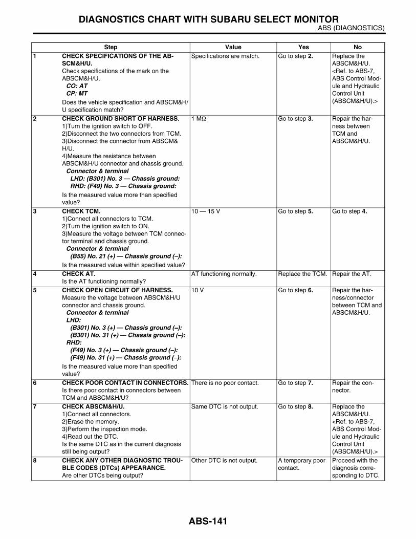
ABS (DIAGNOSTICS)DIAGNOSTICS CHART WITH SUBARU SELECT MONITOR
Step Value Yes No1 CHECK SPECIFICATIONS OF THE AB-
SCM&H/U.Check specifications of the mark on the ABSCM&H/U.
CO: AT CP: MT
Does the vehicle specification and ABSCM&H/U specification match?
Specifications are match. Go to step 2. Replace the ABSCM&H/U. <Ref. to ABS-7, ABS Control Mod-ule and Hydraulic Control Unit (ABSCM&H/U).>
2 CHECK GROUND SHORT OF HARNESS.1)Turn the ignition switch to OFF.2)Disconnect the two connectors from TCM.3)Disconnect the connector from ABSCM&H/U.4)Measure the resistance between ABSCM&H/U connector and chassis ground.
Connector & terminalLHD: (B301) No. 3 — Chassis ground:RHD: (F49) No. 3 — Chassis ground:
Is the measured value more than specified value?
1 MΩ Go to step 3. Repair the har-ness between TCM and ABSCM&H/U.
3 CHECK TCM.1)Connect all connectors to TCM.2)Turn the ignition switch to ON.3)Measure the voltage between TCM connec-tor terminal and chassis ground.
Connector & terminal(B55) No. 21 (+) — Chassis ground (−−−−):
Is the measured value within specified value?
10 — 15 V Go to step 5. Go to step 4.
4 CHECK AT.Is the AT functioning normally?
AT functioning normally. Replace the TCM. Repair the AT.
5 CHECK OPEN CIRCUIT OF HARNESS.Measure the voltage between ABSCM&H/U connector and chassis ground.
Connector & terminalLHD:
(B301) No. 3 (+) — Chassis ground (−−−−):(B301) No. 31 (+) — Chassis ground (−−−−):
RHD:(F49) No. 3 (+) — Chassis ground (−−−−):(F49) No. 31 (+) — Chassis ground (−−−−):
Is the measured value more than specified value?
10 V Go to step 6. Repair the har-ness/connector between TCM and ABSCM&H/U.
6 CHECK POOR CONTACT IN CONNECTORS.Is there poor contact in connectors between TCM and ABSCM&H/U?
There is no poor contact. Go to step 7. Repair the con-nector.
7 CHECK ABSCM&H/U.1)Connect all connectors.2)Erase the memory.3)Perform the inspection mode.4)Read out the DTC.Is the same DTC as in the current diagnosis still being output?
Same DTC is not output. Go to step 8. Replace the ABSCM&H/U. <Ref. to ABS-7, ABS Control Mod-ule and Hydraulic Control Unit (ABSCM&H/U).>
8 CHECK ANY OTHER DIAGNOSTIC TROU-BLE CODES (DTCs) APPEARANCE.Are other DTCs being output?
Other DTC is not output. A temporary poor contact.
Proceed with the diagnosis corre-sponding to DTC.
ABS-141

ABS (DIAGNOSTICS)DIAGNOSTICS CHART WITH SUBARU SELECT MONITOR
X: DTC 44 — ABS-AT CONTROL (CONTROLLED) —
DIAGNOSIS:• Combination of AT control faultsTROUBLE SYMPTOM:• ABS does not operate.WIRING DIAGRAM:
ABS00239
B55
1 2 3 4 5 6 7 8 9 10 11 12 13 14 1516 17 18 19 20 21 22
27 28 29 30 3123 24 25 26
ABS CONTROL MODULE ANDHYDRAULIC CONTROL UNIT
313
TCMB55
21
1 2 3 410 11 1219 20 21
135 614 15
7 8 916 17 1822 23 24
B301
F49
LHD
RHD
:
:
: LHD MODEL
: RHD MODEL
LHD
RHD
B301
F49
LHD
RHD
:
:
ABS-142

ABS (DIAGNOSTICS)DIAGNOSTICS CHART WITH SUBARU SELECT MONITOR
Step Value Yes No1 CHECK BATTERY SHORT OF HARNESS.
1)Turn the ignition switch to OFF.2)Disconnect all connectors from TCM.3)Disconnect the connector from ABSCM&H/U.4)Measure the voltage between ABSCM&H/U connector and chassis ground.
Connector & terminalLHD: (B301) No. 3 (+) — Chassis ground (−−−−):RHD: (F49) No. 3 (+) — Chassis ground (−−−−):
Is the measured value less than specified value?
1 V Go to step 2. Repair the har-ness between TCM and ABSCM&H/U.
2 CHECK BATTERY SHORT OF HARNESS.1)Turn the ignition switch to ON.2)Measure the voltage between ABSCM&H/U connector and chassis ground.
Connector & terminalLHD: (B301) No. 3 (+) — Chassis ground (−−−−):RHD: (F49) No. 3 (+) — Chassis ground (−−−−):
Is the measured value less than specified value?
1 V Go to step 3. Repair the har-ness between TCM and ABSCM&H/U.
3 CHECK OPEN CIRCUIT OF HARNESS.1)Turn the ignition switch to OFF.2)Connect all connectors to TCM.3)Turn the ignition switch to ON.4)Measure the voltage between ABSCM&H/U connector and chassis ground.
Connector & terminalLHD:
(B301) No. 3 (+) — Chassis ground (−−−−):(B301) No. 31 (+) — Chassis ground (−−−−):
RHD:(F49) No. 3 (+) — Chassis ground (−−−−):(F49) No. 31 (+) — Chassis ground (−−−−):
Is the measured value within specified value?
10 — 13 V Go to step 4. Repair the har-ness/connector between TCM and ABSCM&H/U.
4 CHECK POOR CONTACT IN CONNECTORS.Turn the ignition switch to OFF.Is there poor contact in connectors between TCM and ABSCM&H/U?
There is no poor contact. Go to step 5. Repair the con-nector.
5 CHECK ABSCM&H/U.1)Connect all connectors.2)Erase the memory.3)Perform the inspection mode.4)Read out the DTC.Is the same DTC as in current diagnosis still being output?
Same DTC is not output. Go to step 6. Replace the ABSCM&H/U. <Ref. to ABS-7, ABS Control Mod-ule and Hydraulic Control Unit (ABSCM&H/U).>
6 CHECK ANY OTHER DIAGNOSTIC TROU-BLE CODES (DTCs) APPEARANCE.Are other DTCs being output?
Other DTC is not output. A temporary poor contact.
Proceed with the diagnosis corre-sponding to DTC.
ABS-143
ABS (DIAGNOSTICS)DIAGNOSTICS CHART WITH SUBARU SELECT MONITOR
Y: DTC 51 — VALVE RELAY MALFUNCTION —
DIAGNOSIS:• Faulty valve relayTROUBLE SYMPTOM:• ABS does not operate.• EBD does not operate.
NOTE:In addition to the ABS warning light, brake warning light illuminates.
ABS-144

ABS (DIAGNOSTICS)DIAGNOSTICS CHART WITH SUBARU SELECT MONITOR
WIRING DIAGRAM:
ABS00244
EE
26
24
23
ABS CONTROL MODULE ANDHYDRAULIC CONTROL UNIT
VALVE RELAY
1
MOTOR RELAY
SO
LE
NO
ID
VA
LV
E
PU
MP
M
OT
OR
M
FL
IN
LE
T
RL
IN
LE
T
FR
IN
LE
T
RR
IN
LE
T
FL
OU
TL
ET
RL
OU
TL
ET
FR
OU
TL
ET
RR
OU
TL
ET
BATTERY
SBF-1SBF-3
SB
F-4
No
.18
No
.8
EIGNITIONSWITCH
F44
B61
2
1 2 3 45 6 7 8
F44
1 2 3 4 5 6 7 8 9 10 11 12 13 14 1516 17 18 19 20 21 22
27 28 29 30 3123 24 25 26
: LHD MODEL
: RHD MODEL
LHD
RHD
B301
F49
LHD
RHD
:
:
B301
F49
LHD
RHD
:
:
RHD
RHD
LH
DL
HD
ABS-145
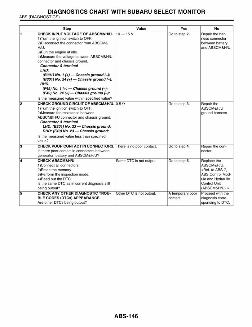
ABS (DIAGNOSTICS)DIAGNOSTICS CHART WITH SUBARU SELECT MONITOR
Step Value Yes No1 CHECK INPUT VOLTAGE OF ABSCM&H/U.
1)Turn the ignition switch to OFF.2)Disconnect the connector from ABSCM&H/U.3)Run the engine at idle.4)Measure the voltage between ABSCM&H/U connector and chassis ground.
Connector & terminalLHD:
(B301) No. 1 (+) — Chassis ground (−−−−):(B301) No. 24 (+) — Chassis ground (−−−−):
RHD:(F49) No. 1 (+) — Chassis ground (−−−−):(F49) No. 24 (+) — Chassis ground (−−−−):
Is the measured value within specified value?
10 — 15 V Go to step 2. Repair the har-ness connector between battery and ABSCM&H/U.
2 CHECK GROUND CIRCUIT OF ABSCM&H/U.1)Turn the ignition switch to OFF.2)Measure the resistance between ABSCM&H/U connector and chassis ground.
Connector & terminalLHD: (B301) No. 23 — Chassis ground:RHD: (F49) No. 23 — Chassis ground:
Is the measured value less than specified value?
0.5 Ω Go to step 3. Repair the ABSCM&H/U ground harness.
3 CHECK POOR CONTACT IN CONNECTORS.Is there poor contact in connectors between generator, battery and ABSCM&H/U?
There is no poor contact. Go to step 4. Repair the con-nector.
4 CHECK ABSCM&H/U.1)Connect all connectors.2)Erase the memory.3)Perform the inspection mode.4)Read out the DTC.Is the same DTC as in current diagnosis still being output?
Same DTC is not output. Go to step 5. Replace the ABSCM&H/U. <Ref. to ABS-7, ABS Control Mod-ule and Hydraulic Control Unit (ABSCM&H/U).>
5 CHECK ANY OTHER DIAGNOSTIC TROU-BLE CODES (DTCs) APPEARANCE.Are other DTCs being output?
Other DTC is not output. A temporary poor contact.
Proceed with the diagnosis corre-sponding to DTC.
ABS-146

ABS (DIAGNOSTICS)DIAGNOSTICS CHART WITH SUBARU SELECT MONITOR
Z: DTC 51 — VALVE RELAY ON FAILURE —
DIAGNOSIS:• Faulty valve relayTROUBLE SYMPTOM:• ABS does not operate.WIRING DIAGRAM:
ABS00244
EE
26
24
23
ABS CONTROL MODULE ANDHYDRAULIC CONTROL UNIT
VALVE RELAY
1
MOTOR RELAY
SO
LE
NO
ID
VA
LV
E
PU
MP
M
OT
OR
M
FL
IN
LE
T
RL
IN
LE
T
FR
IN
LE
T
RR
IN
LE
T
FL
OU
TL
ET
RL
OU
TL
ET
FR
OU
TL
ET
RR
OU
TL
ET
BATTERY
SBF-1SBF-3
SB
F-4
No
.18
No
.8
EIGNITIONSWITCH
F44
B61
2
1 2 3 45 6 7 8
F44
1 2 3 4 5 6 7 8 9 10 11 12 13 14 1516 17 18 19 20 21 22
27 28 29 30 3123 24 25 26
: LHD MODEL
: RHD MODEL
LHD
RHD
B301
F49
LHD
RHD
:
:
B301
F49
LHD
RHD
:
:
RHD
RHD
LH
DL
HD
ABS-147

ABS (DIAGNOSTICS)DIAGNOSTICS CHART WITH SUBARU SELECT MONITOR
Step Value Yes No1 CHECK VALVE RELAY IN ABSCM&H/U.
1)Disconnect the connector from ABSCM&H/U.2)Measure the resistance between ABSCM&H/U terminals.
TerminalsNo. 23 — No. 24:
Is the measured value more than specified value?
1 MΩ Go to step 2. Replace the ABSCM&H/U. <Ref. to ABS-7, ABS Control Mod-ule and Hydraulic Control Unit (ABSCM&H/U).>
2 CHECK POOR CONTACT IN CONNECTORS.Is there poor contact in connectors between generator, battery and ABSCM&H/U?
There is no poor contact. Go to step 3. Repair the con-nector.
3 CHECK ABSCM&H/U.1)Connect all connectors.2)Erase the memory.3)Perform the inspection mode.4)Read out the DTC.Is the same DTC as in current diagnosis still being output?
Same DTC is not output. Go to step 4. Replace the ABSCM&H/U. <Ref. to ABS-7, ABS Control Mod-ule and Hydraulic Control Unit (ABSCM&H/U).>
4 CHECK ANY OTHER DIAGNOSTIC TROU-BLE CODES (DTCs) APPEARANCE.Are other DTCs being output?
Other DTC is not output. A temporary poor contact.
Proceed with the diagnosis corre-sponding to DTC.
ABS-148

ABS (DIAGNOSTICS)DIAGNOSTICS CHART WITH SUBARU SELECT MONITOR
AA:DTC 52 — OPEN CIRCUIT IN MOTOR RELAY CIRCUIT —
DIAGNOSIS:• Faulty motor• Faulty motor relay• Faulty harness connectorTROUBLE SYMPTOM:• ABS does not operate.WIRING DIAGRAM:
ABS00249
EE
26
25
23
ABS CONTROL MODULE ANDHYDRAULIC CONTROL UNIT
VALVE RELAY
1
MOTOR RELAY
SO
LE
NO
ID
VA
LV
E
PU
MP
M
OT
OR
M
FL
IN
LE
T
RL
IN
LE
T
FR
IN
LE
T
RR
IN
LE
T
FL
OU
TL
ET
RL
OU
TL
ET
FR
OU
TL
ET
RR
OU
TL
ET
BATTERY
SBF-1
SB
F-4
SB
F
HO
LD
ER
No
.18
EIGNITIONSWITCH
F44
B61
1
1 2 3 45 6 7 8
F44
1 2 3 4 5 6 7 8 9 10 11 12 13 14 1516 17 18 19 20 21 22
27 28 29 30 3123 24 25 26
B301
F49
LHD
RHD
:
:
B301
F49
LHD
RHD
:
:
: LHD MODEL
: RHD MODEL
LHD
RHD
RHD
LH
DL
HD
RHD
4
F96
B255
B61
F44
ABS-149

ABS (DIAGNOSTICS)DIAGNOSTICS CHART WITH SUBARU SELECT MONITOR
Step Value Yes No1 CHECK INPUT VOLTAGE OF ABSCM&H/U.
1)Turn the ignition switch to OFF.2)Disconnect the connector from ABSCM&H/U.3)Turn the ignition switch to ON.4)Measure the voltage between ABSCM&H/U connector and chassis ground.
Connector & terminalLHD: (B301) No. 25 (+) — Chassis ground (−−−−):RHD: (F49) No. 25 (+) — Chassis ground (−−−−):
Is the measured value within specified value?
10 — 13 V Go to step 2. Repair the har-ness/connector between battery and ABSCM&H/U and check fuse SBF8.
2 CHECK GROUND CIRCUIT OF MOTOR.1)Turn the ignition switch to OFF.2)Measure the resistance between ABSCM&H/U connector and chassis ground.
Connector & terminalLHD: (B301) No. 26 — Chassis ground:RHD: (F49) No. 26 — Chassis ground:
Is the measured value less than specified value?
0.5 Ω Go to step 3. Repair the ABSCM&H/U ground harness.
3 CHECK MOTOR OPERATION.Operate the sequence control. <Ref. to ABS-11, ABS Sequence Control.>
NOTE:Use the diagnosis connector to operate se-quence control.Can motor revolution noise (buzz) be heard when carrying out the check sequence?
Motor revolution noise (buzz) can be heard.
Go to step 4. Replace the ABSCM&H/U. <Ref. to ABS-7, ABS Control Mod-ule and Hydraulic Control Unit (ABSCM&H/U).>
4 CHECK POOR CONTACT IN CONNECTORS.Turn the ignition switch to OFF.Is there poor contact in connector between generator, battery and ABSCM&H/U?
There is no poor contact. Go to step 5. Repair the con-nector.
5 CHECK ABSCM&H/U.1)Connect all connectors.2)Erase the memory.3)Perform the inspection mode.4)Read out the DTC.Is the same DTC as in current diagnosis still being output?
Same DTC is not output. Go to step 6. Replace the ABSCM&H/U. <Ref. to ABS-7, ABS Control Mod-ule and Hydraulic Control Unit (ABSCM&H/U).>
6 CHECK ANY OTHER DIAGNOSTIC TROU-BLE CODES (DTCs) APPEARANCE.Are other DTCs being output?
Other DTC is not output. A temporary poor contact.
Proceed with the diagnosis corre-sponding to DTC.
ABS-150

ABS (DIAGNOSTICS)DIAGNOSTICS CHART WITH SUBARU SELECT MONITOR
AB:DTC 52 — MOTOR RELAY ON FAILURE —
DIAGNOSIS:• Faulty motor• Faulty motor relay• Faulty harness connectorTROUBLE SYMPTOM:• ABS does not operate.WIRING DIAGRAM:
ABS00249
EE
26
25
23
ABS CONTROL MODULE ANDHYDRAULIC CONTROL UNIT
VALVE RELAY
1
MOTOR RELAY
SO
LE
NO
ID
VA
LV
E
PU
MP
M
OT
OR
M
FL
IN
LE
T
RL
IN
LE
T
FR
IN
LE
T
RR
IN
LE
T
FL
OU
TL
ET
RL
OU
TL
ET
FR
OU
TL
ET
RR
OU
TL
ET
BATTERY
SBF-1
SB
F-4
SB
F
HO
LD
ER
No
.18
EIGNITIONSWITCH
F44
B61
1
1 2 3 45 6 7 8
F44
1 2 3 4 5 6 7 8 9 10 11 12 13 14 1516 17 18 19 20 21 22
27 28 29 30 3123 24 25 26
B301
F49
LHD
RHD
:
:
B301
F49
LHD
RHD
:
:
: LHD MODEL
: RHD MODEL
LHD
RHD
RHD
LH
DL
HD
RHD
4
F96
B255
B61
F44
ABS-151

ABS (DIAGNOSTICS)DIAGNOSTICS CHART WITH SUBARU SELECT MONITOR
Step Value Yes No1 CHECK MOTOR RELAY IN ABSCM&H/U.
1)Disconnect the connector from ABSCM&H/U.2)Measure the resistance between ABSCM&H/U terminals.
TerminalsNo. 25 — No. 26:
Is the measured value more than specified value?
1 MΩ Go to step 2. Replace the ABSCM&H/U. <Ref. to ABS-7, ABS Control Mod-ule and Hydraulic Control Unit (ABSCM&H/U).>
2 CHECK MOTOR OPERATION.Operate the sequence control. <Ref. to ABS-11, ABS Sequence Control.>
NOTE:Use the diagnosis connector to operate se-quence control.Can motor revolution noise (buzz) be heard when carrying out the sequence control?
Motor revolution noise (buzz) can be heard.
Go to step 3. Replace the ABSCM&H/U. <Ref. to ABS-7, ABS Control Mod-ule and Hydraulic Control Unit (ABSCM&H/U).>
3 CHECK POOR CONTACT IN CONNECTORS.Turn the ignition switch to OFF.Is there poor contact in connector between generator, battery and ABSCM&H/U?
There is no poor contact. Go to step 4. Repair the con-nector.
4 CHECK ABSCM&H/U.1)Connect all connectors.2)Erase the memory.3)Perform the inspection mode.4)Read out the DTC.Is the same DTC as in current diagnosis still being output?
Same DTC is not output. Go to step 5. Replace the ABSCM&H/U. <Ref. to ABS-7, ABS Control Mod-ule and Hydraulic Control Unit (ABSCM&H/U).>
5 CHECK ANY OTHER DIAGNOSTIC TROU-BLE CODES (DTCs) APPEARANCE.Are other DTCs being output?
Other DTC is not output. A temporary poor contact.
NOTE:Although the ABSwarning light re-mains illuminatingat this point, this isa normal condition.Vehicle must bedriven at approx.12 km/h (7.46MPH) or faster toturn off ABS warn-ing light. Makesure that the ABSwarning light goesoff after driving ve-hicle.
Proceed with the diagnosis corre-sponding to DTC.
ABS-152
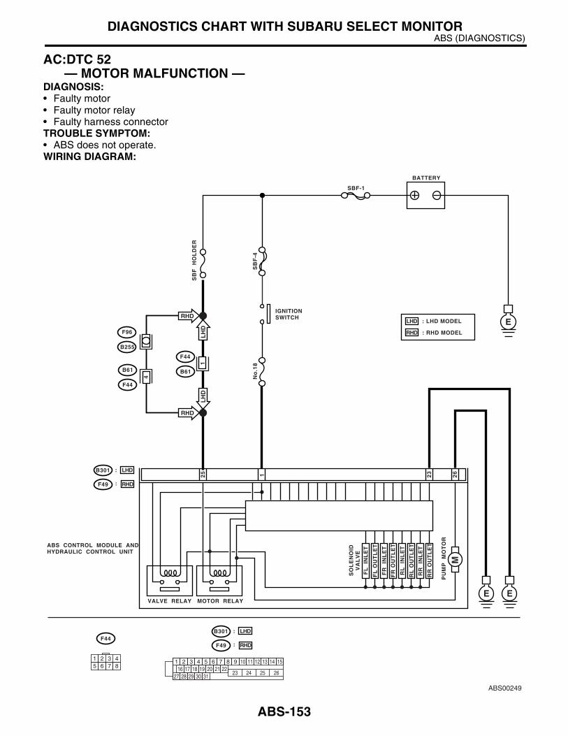
ABS (DIAGNOSTICS)DIAGNOSTICS CHART WITH SUBARU SELECT MONITOR
AC:DTC 52 — MOTOR MALFUNCTION —
DIAGNOSIS:• Faulty motor• Faulty motor relay• Faulty harness connectorTROUBLE SYMPTOM:• ABS does not operate.WIRING DIAGRAM:
ABS00249
EE
26
25
23
ABS CONTROL MODULE ANDHYDRAULIC CONTROL UNIT
VALVE RELAY
1
MOTOR RELAY
SO
LE
NO
ID
VA
LV
E
PU
MP
M
OT
OR
M
FL
IN
LE
T
RL
IN
LE
T
FR
IN
LE
T
RR
IN
LE
T
FL
OU
TL
ET
RL
OU
TL
ET
FR
OU
TL
ET
RR
OU
TL
ET
BATTERY
SBF-1
SB
F-4
SB
F
HO
LD
ER
No
.18
EIGNITIONSWITCH
F44
B61
1
1 2 3 45 6 7 8
F44
1 2 3 4 5 6 7 8 9 10 11 12 13 14 1516 17 18 19 20 21 22
27 28 29 30 3123 24 25 26
B301
F49
LHD
RHD
:
:
B301
F49
LHD
RHD
:
:
: LHD MODEL
: RHD MODEL
LHD
RHD
RHD
LH
DL
HD
RHD
4
F96
B255
B61
F44
ABS-153

ABS (DIAGNOSTICS)DIAGNOSTICS CHART WITH SUBARU SELECT MONITOR
Step Value Yes No1 CHECK INPUT VOLTAGE OF ABSCM&H/U.
1)Turn the ignition switch to OFF.2)Disconnect the connector from ABSCM&H/U.3)Turn the ignition switch to ON.4)Measure the voltage between ABSCM&H/U connector and chassis ground.
Connector & terminalLHD: (B301) No. 25 (+) — Chassis ground (−−−−):RHD: (F49) No. 25 (+) — Chassis ground (−−−−):
Is the measured value within specified value?
10 — 13 V Go to step 2. Repair the har-ness/connector between battery and ABSCM&H/U and check fuse SBF8.
2 CHECK GROUND CIRCUIT OF MOTOR.1)Turn the ignition switch to OFF.2)Measure the resistance between ABSCM&H/U connector and chassis ground.
Connector & terminalLHD: (B301) No. 26 — Chassis ground:RHD: (F49) No. 26 — Chassis ground:
Is the measured value less than specified value?
0.5 Ω Go to step 3. Repair the ABSCM&H/U ground harness.
3 CHECK INPUT VOLTAGE OF ABSCM&H/U.1)Run the engine at idle.2)Measure the voltage between ABSCM&H/U connector and chassis ground.
Connector & terminalLHD: (B301) No. 1 (+) — Chassis ground (−−−−):RHD: (F49) No. 1 (+) — Chassis ground (−−−−):
Is the measured value within specified value?
10 — 15 V Go to step 4. Repair the har-ness connector between battery, ignition switch and ABSCM&H/U.
4 CHECK GROUND CIRCUIT OF ABSCM&H/U.1)Turn the ignition switch to OFF.2)Measure the resistance between ABSCM&H/U connector and chassis ground.
Connector & terminalLHD: (B301) No. 23 — Chassis ground:RHD: (F49) No. 23 — Chassis ground:
Is the measured value less than specified value?
0.5 Ω Go to step 5. Repair the ABSCM&H/U ground harness.
5 CHECK MOTOR OPERATION.Operate the sequence control. <Ref. to ABS-11, ABS Sequence Control.>
NOTE:Use the diagnosis connector to operate se-quence control.
Can motor revolution noise (buzz) be heard when carrying out the sequence control?
Motor revolution noise (buzz) can be heard.
Go to step 6. Replace the ABSCM&H/U. <Ref. to ABS-7, ABS Control Mod-ule and Hydraulic Control Unit (ABSCM&H/U).>
6 CHECK POOR CONTACT IN CONNECTORS.Turn the ignition switch to OFF.Is there poor contact in connector between generator, battery and ABSCM&H/U?
There is no poor contact. Go to step 7. Repair the con-nector.
ABS-154

ABS (DIAGNOSTICS)DIAGNOSTICS CHART WITH SUBARU SELECT MONITOR
7 CHECK ABSCM&H/U.1)Connect all connectors.2)Erase the memory.3)Perform the inspection mode.4)Read out the DTC.Is the same DTC as in current diagnosis still being output?
Same DTC is not output. Go to step 8. Replace the ABSCM&H/U. <Ref. to ABS-7, ABS Control Mod-ule and Hydraulic Control Unit (ABSCM&H/U).>
8 CHECK ANY OTHER DIAGNOSTIC TROU-BLE CODES (DTCs) APPEARANCE.Are other DTCs being output?
Other DTC is not output. A temporary poor contact.
Proceed with the diagnosis corre-sponding to DTC.
Step Value Yes No
ABS-155

ABS (DIAGNOSTICS)DIAGNOSTICS CHART WITH SUBARU SELECT MONITOR
AD:DTC 54 — STOP LIGHT SWITCH SIGNAL CIRCUIT MALFUNCTION —
DIAGNOSIS:• Faulty stop light switchTROUBLE SYMPTOM:• ABS does not operate.WIRING DIAGRAM:
Step Value Yes No1 CHECK OUTPUT OF STOP LIGHT SWITCH
USING SELECT MONITOR.1)Select “Current data display & Save” on the select monitor.2)Release the brake pedal.3)Read the stop light switch output in select monitor data display.Is the reading indicated on monitor display less than specified value?
1.5 V Go to step 2. Go to step 3.
ABS00254
BATTERY
SB
F-1
SB
F-2
No
.16
B64
1 22 3
OC
OC
:
E
2
ABS CONTROL MODULE ANDHYDRAULIC CONTROL UNIT
STOP LIGHTSWITCH
B65 WC
WC
:
OC WITHOUT CRUISECONTROL
WITH CRUISECONTROL
:
WC :
B64 B65
1 2 1 2 3 4 5 6 7 8 9 10 11 12 13 14 1516 17 18 19 20 21 22
27 28 29 30 3123 24 25 26
1 23 4
: LHD MODEL
: RHD MODEL
LHD
RHD
B301
F49
LHD
RHD
:
:
B301
F49
LHD
RHD
:
:
RHD
LH
D
6
B61
F44
RHD
LH
D
F44
1 45 6 7 8
2 3
ABS-156
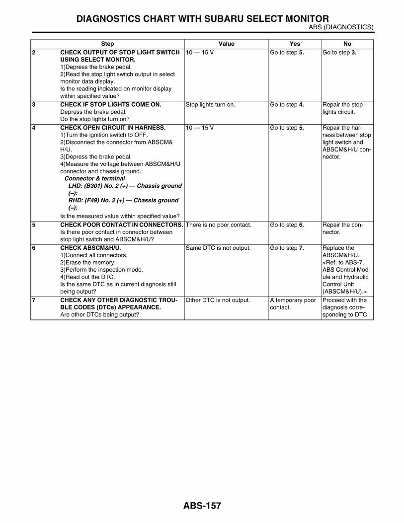
ABS (DIAGNOSTICS)DIAGNOSTICS CHART WITH SUBARU SELECT MONITOR
2 CHECK OUTPUT OF STOP LIGHT SWITCH USING SELECT MONITOR.1)Depress the brake pedal.2)Read the stop light switch output in select monitor data display.Is the reading indicated on monitor display within specified value?
10 — 15 V Go to step 5. Go to step 3.
3 CHECK IF STOP LIGHTS COME ON.Depress the brake pedal.Do the stop lights turn on?
Stop lights turn on. Go to step 4. Repair the stop lights circuit.
4 CHECK OPEN CIRCUIT IN HARNESS.1)Turn the ignition switch to OFF.2)Disconnect the connector from ABSCM&H/U.3)Depress the brake pedal.4)Measure the voltage between ABSCM&H/U connector and chassis ground.
Connector & terminalLHD: (B301) No. 2 (+) — Chassis ground (−−−−):RHD: (F49) No. 2 (+) — Chassis ground (−−−−):
Is the measured value within specified value?
10 — 15 V Go to step 5. Repair the har-ness between stop light switch and ABSCM&H/U con-nector.
5 CHECK POOR CONTACT IN CONNECTORS.Is there poor contact in connector between stop light switch and ABSCM&H/U?
There is no poor contact. Go to step 6. Repair the con-nector.
6 CHECK ABSCM&H/U.1)Connect all connectors.2)Erase the memory.3)Perform the inspection mode.4)Read out the DTC.Is the same DTC as in current diagnosis still being output?
Same DTC is not output. Go to step 7. Replace the ABSCM&H/U. <Ref. to ABS-7, ABS Control Mod-ule and Hydraulic Control Unit (ABSCM&H/U).>
7 CHECK ANY OTHER DIAGNOSTIC TROU-BLE CODES (DTCs) APPEARANCE.Are other DTCs being output?
Other DTC is not output. A temporary poor contact.
Proceed with the diagnosis corre-sponding to DTC.
Step Value Yes No
ABS-157
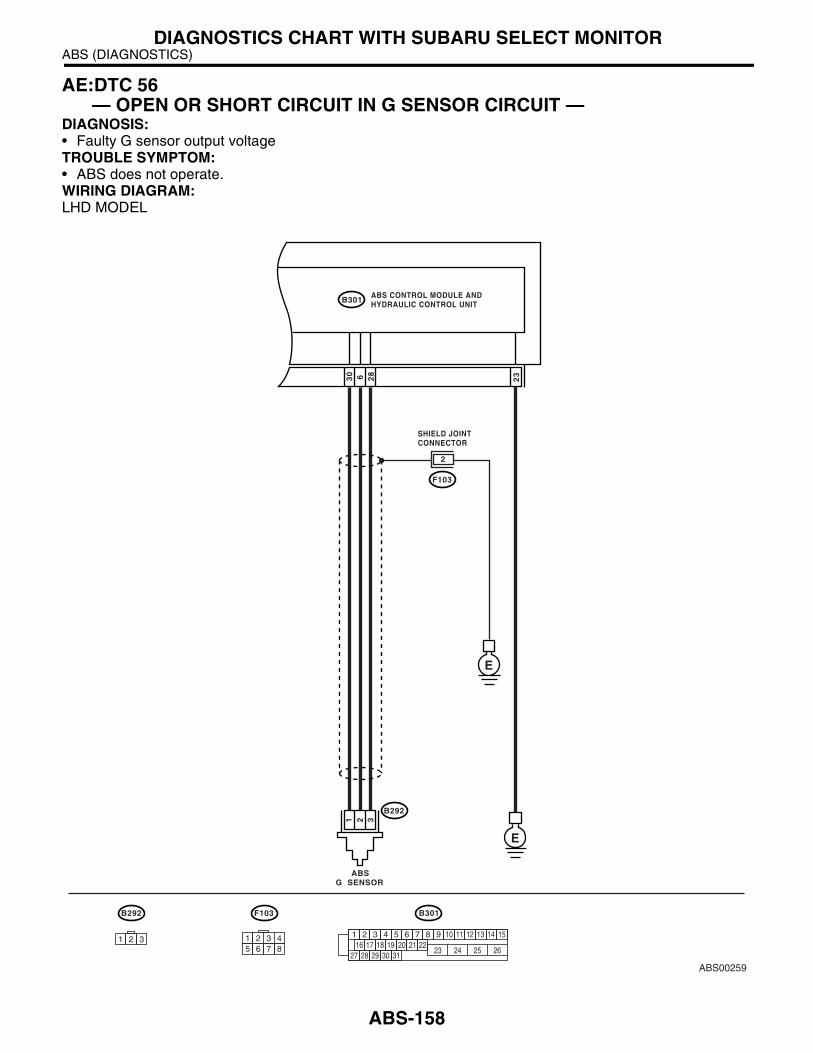
ABS (DIAGNOSTICS)DIAGNOSTICS CHART WITH SUBARU SELECT MONITOR
AE:DTC 56 — OPEN OR SHORT CIRCUIT IN G SENSOR CIRCUIT —
DIAGNOSIS:• Faulty G sensor output voltageTROUBLE SYMPTOM:• ABS does not operate.WIRING DIAGRAM:LHD MODEL
ABS00259
ABS CONTROL MODULE ANDHYDRAULIC CONTROL UNITB301
F103 B301
1 2 3 4 5 6 7 8 9 10 11 12 13 14 1516 17 18 19 20 21 22
27 28 29 30 3123 24 25 26
1 2 3 45 6 7 8
28
30 6 23
F103
B292
ABSG SENSOR
E
E
2
321
B292
1 2 3
SHIELD JOINTCONNECTOR
ABS-158
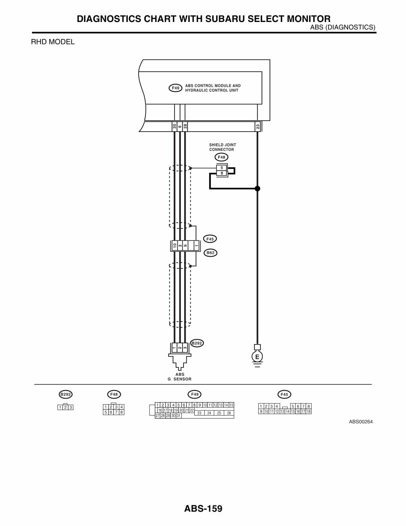
ABS (DIAGNOSTICS)DIAGNOSTICS CHART WITH SUBARU SELECT MONITOR
RHD MODEL
ABS00264
ABS CONTROL MODULE ANDHYDRAULIC CONTROL UNITF49
F48 F49
1 2 3 4 5 6 7 8 9 10 11 12 13 14 1516 17 18 19 20 21 22
27 28 29 30 3123 24 25 26
1 2 3 45 6 7 8
28
30 6 23
F48
B292
ABSG SENSOR
E
321
B292
1 2 3
SHIELD JOINTCONNECTOR
85
9
F45
B62
210 1
10 11 12 13 14 15 16 17 181 2 3 4 7 85 69
F45
ABS-159

ABS (DIAGNOSTICS)DIAGNOSTICS CHART WITH SUBARU SELECT MONITOR
Step Value Yes No1 CHECK OUTPUT OF G SENSOR USING SE-
LECT MONITOR.1)Select “Current data display & Save” on the select monitor.2)Read the G sensor output in select monitor data display.Is the G sensor output on monitor display within specified value when G sensor is in hori-zontal position?
2.1 — 2.5 V Go to step 2. Go to step 5.
2 CHECK POOR CONTACT IN CONNECTORS.Is there poor contact in connector between ABSCM&H/U and G sensor?
There is no poor contact. Go to step 3. Repair the con-nector.
3 CHECK ABSCM&H/U.1)Connect all connectors.2)Erase the memory.3)Perform the inspection mode.4)Read out the DTC.Is the same DTC as in the current diagnosis still being output?
Same DTC is not output. Go to step 4. Replace the ABSCM&H/U. <Ref. to ABS-7, ABS Control Mod-ule and Hydraulic Control Unit (ABSCM&H/U).>
4 CHECK ANY OTHER DIAGNOSTIC TROU-BLE CODES (DTCs) APPEARANCE.Are other DTCs being output?
Other DTC is not output. A temporary poor contact.
Proceed with the diagnosis corre-sponding to DTC.
5 CHECK INPUT VOLTAGE OF G SENSOR.1)Turn the ignition switch to OFF.2)Remove the console box.3)Remove the G sensor from vehicle. (Do not disconnect connector.)4)Turn the ignition switch to ON.5)Measure the voltage between G sensor con-nector terminals.
Connector & terminal(B292) No. 1 (+) — No. 3 (−−−−):
Is the measured value within specified value?
4.75 — 5.25 V Go to step 6. Repair the har-ness/connector between G sensor and ABSCM&H/U.
6 CHECK OPEN CIRCUIT IN G SENSOR OUT-PUT HARNESS AND GROUND HARNESS.1)Turn the ignition switch to OFF.2)Disconnect the connector from ABSCM&H/U.3)Measure the resistance between ABSCM&H/U connector terminals.
Connector & terminalLHD: (B301) No. 6 — No. 28:RHD: (F49) No. 6 — No. 28:
Is the measured value within specified value?
5.0 — 5.6 kΩ Go to step 7. Repair the har-ness/connector between G sensor and ABSCM&H/U.
7 CHECK GROUND SHORT IN G SENSOR OUTPUT HARNESS.1)Disconnect the connector from G sensor.2)Measure the resistance between ABSCM&H/U connector and chassis ground.
Connector & terminalLHD: (B301) No. 6 — Chassis ground:RHD: (F49) No. 6 — Chassis ground:
Is the measured value more than specified value?
1 MΩ Go to step 8. Repair the har-ness between G sensor and ABSCM&H/U.
ABS-160

ABS (DIAGNOSTICS)DIAGNOSTICS CHART WITH SUBARU SELECT MONITOR
8 CHECK G SENSOR.1)Connect the connector to G sensor.2)Connect the connector to ABSCM&H/U.3)Turn the ignition switch to ON.4)Measure the voltage between G sensor con-nector terminals.
Connector & terminal(B292) No. 2 (+) — No. 3 (−−−−):
Is the measured value within specified value when G sensor is in horizontal position?
2.1 — 2.5 V Go to step 9. Replace the G sensor. <Ref. to ABS-22, G Sen-sor.>
9 CHECK G SENSOR.Measure the voltage between G sensor con-nector terminals.
Connector & terminal(B292) No. 2 (+) — No. 3 (−−−−):
Is the measured value within specified value when G sensor is inclined forwards to 90°?
3.7 — 4.1 V Go to step 10. Replace the G sensor. <Ref. to ABS-22, G Sen-sor.>
10 CHECK G SENSOR.Measure the voltage between G sensor con-nector terminals.
Connector & terminal(B292) No. 2 (+) — No. 3 (−−−−):
Is the measured value within specified value when G sensor is inclined backwards to 90°?
0.5 — 0.9 V Go to step 11. Replace the G sensor. <Ref. to ABS-22, G Sen-sor.>
11 CHECK POOR CONTACT IN CONNECTORS.Turn the ignition switch to OFF.Is there poor contact in connector between ABSCM&H/U and G sensor?
There is no poor contact. Go to step 12. Repair the con-nector.
12 CHECK ABSCM&H/U.1)Connect all connectors.2)Erase the memory.3)Perform the inspection mode.4)Read out the DTC.Is the same DTC as in current diagnosis still being output?
Same DTC is not output. Go to step 13. Replace the ABSCM&H/U. <Ref. to ABS-7, ABS Control Mod-ule and Hydraulic Control Unit (ABSCM&H/U).>
13 CHECK ANY OTHER DIAGNOSTIC TROU-BLE CODES (DTCs) APPEARANCE.Are other DTCs being output?
Other DTC is not output. A temporary poor contact.
Proceed with the diagnosis corre-sponding to DTC.
Step Value Yes No
ABS-161

ABS (DIAGNOSTICS)DIAGNOSTICS CHART WITH SUBARU SELECT MONITOR
AF:DTC 56 — BATTERY SHORT IN G SENSOR CIRCUIT —
DIAGNOSIS:• Faulty G sensor output voltageTROUBLE SYMPTOM:• ABS does not operate.WIRING DIAGRAM:LHD MODEL
ABS00259
ABS CONTROL MODULE ANDHYDRAULIC CONTROL UNITB301
F103 B301
1 2 3 4 5 6 7 8 9 10 11 12 13 14 1516 17 18 19 20 21 22
27 28 29 30 3123 24 25 26
1 2 3 45 6 7 8
28
30 6 23
F103
B292
ABSG SENSOR
E
E
2
321
B292
1 2 3
SHIELD JOINTCONNECTOR
ABS-162

ABS (DIAGNOSTICS)DIAGNOSTICS CHART WITH SUBARU SELECT MONITOR
RHD MODEL
ABS00264
ABS CONTROL MODULE ANDHYDRAULIC CONTROL UNITF49
F48 F49
1 2 3 4 5 6 7 8 9 10 11 12 13 14 1516 17 18 19 20 21 22
27 28 29 30 3123 24 25 26
1 2 3 45 6 7 8
28
30 6 23
F48
B292
ABSG SENSOR
E
321
B292
1 2 3
SHIELD JOINTCONNECTOR
85
9
F45
B62
210 1
10 11 12 13 14 15 16 17 181 2 3 4 7 85 69
F45
ABS-163

ABS (DIAGNOSTICS)DIAGNOSTICS CHART WITH SUBARU SELECT MONITOR
Step Value Yes No1 CHECK OUTPUT OF G SENSOR USING SE-
LECT MONITOR.1)Select “Current data display & Save” on the select monitor.2)Read the G sensor output in select monitor data display.Is the measured value within specified value when G sensor is in horizontal position?
2.1 — 2.5 V Go to step 2. Go to step 5.
2 CHECK POOR CONTACT IN CONNECTORS.Is there poor contact in connector between ABSCM&H/U and G sensor?
There is no poor contact. Go to step 3. Repair the con-nector.
3 CHECK ABSCM&H/U.1)Connect all connectors.2)Erase the memory.3)Perform the inspection mode.4)Read out the DTC.Is the same DTC as in current diagnosis still being output?
Same DTC is not output. Go to step 4. Replace the ABSCM&H/U. <Ref. to ABS-7, ABS Control Mod-ule and Hydraulic Control Unit (ABSCM&H/U).>
4 CHECK ANY OTHER DIAGNOSTIC TROU-BLE CODES (DTCs) APPEARANCE.Are other DTCs being output?
Other DTC is not output. A temporary poor contact.
Proceed with the diagnosis corre-sponding to DTC.
5 CHECK FREEZE FRAME DATA.1)Select “Freeze frame data” on the select monitor.2)Read front right wheel speed on the select monitor display.Is the front right wheel speed on monitor dis-play 0 km/h (0 MPH)?
Monitor is displayed 0 km/h (0 MPH).
Go to step 6. Go to step 16.
6 CHECK FREEZE FRAME DATA.Read front left wheel speed on the select mon-itor display.Is the front left wheel speed on monitor display 0 km/h (0 MPH)?
Monitor is displayed 0 km/h (0 MPH).
Go to step 7. Go to step 16.
7 CHECK FREEZE FRAME DATA.Read rear right wheel speed on the select monitor display.Is the rear right wheel speed on monitor dis-play 0 km/h (0 MPH)?
Monitor is displayed 0 km/h (0 MPH).
Go to step 8. Go to step 16.
8 CHECK FREEZE FRAME DATA.Read rear left wheel speed on the select moni-tor display.Is the rear left wheel speed on monitor display 0 km/h (0 MPH)?
Monitor is displayed 0 km/h (0 MPH).
Go to step 9. Go to step 16.
9 CHECK FREEZE FRAME DATA.Read G sensor output on the select monitor display.Is the G sensor output on monitor display more than specified value?
3.65 V Go to step 10. Go to step 16.
10 CHECK OPEN CIRCUIT IN G SENSOR OUT-PUT HARNESS AND GROUND HARNESS.1)Turn the ignition switch to OFF.2)Disconnect the connector from ABSCM&H/U.3)Measure the resistance between ABSCM&H/U connector terminals.
Connector & terminalLHD: (B301) No. 6 — No. 28:RHD: (F49) No. 6 — No. 28:
Is the measured value within specified value?
4.3 — 4.9 kΩ Go to step 11. Repair the har-ness/connector between G sensor and ABSCM&H/U.
ABS-164

ABS (DIAGNOSTICS)DIAGNOSTICS CHART WITH SUBARU SELECT MONITOR
11 CHECK BATTERY SHORT OF HARNESS.1)Turn the ignition switch to OFF.2)Remove the console box.3)Disconnect the connector from G sensor.4)Disconnect the connector from ABSCM&H/U.5)Measure the voltage between ABSCM&H/U connector and chassis ground.
Connector & terminalLHD: (B301) No. 6 (+) — Chassis ground (−−−−):RHD: (F49) No. 6 (+) — Chassis ground (−−−−):
Is the measured value less than specified value?
1 V Go to step 12. Repair the har-ness between G sensor and ABSCM&H/U.
12 CHECK BATTERY SHORT OF HARNESS.1)Turn the ignition switch to ON.2)Measure the voltage between ABSCM&H/U connector and chassis ground.
Connector & terminalLHD: (B301) No. 6 (+) — Chassis ground (−−−−):RHD: (F49) No. 6 (+) — Chassis ground (−−−−):
Is the measured value less than specified value?
1 V Go to step 13. Repair the har-ness between G sensor and ABSCM&H/U.
13 CHECK POOR CONTACT IN CONNECTORS.Is there poor contact in connector between ABSCM&H/U and G sensor?
There is no poor contact. Go to step 14. Repair the con-nector.
14 CHECK ABSCM&H/U.1)Connect all connectors.2)Erase the memory.3)Perform the inspection mode.4)Read out the DTC.Is the same DTC as in current diagnosis still being output?
Same DTC is not output. Go to step 15. Replace the ABSCM&H/U. <Ref. to ABS-7, ABS Control Mod-ule and Hydraulic Control Unit (ABSCM&H/U).>
15 CHECK ANY OTHER DIAGNOSTIC TROU-BLE CODES (DTCs) APPEARANCE.Are other DTCs being output?
Other DTC is not output. A temporary poor contact.
Proceed with the diagnosis corre-sponding to DTC.
16 CHECK INPUT VOLTAGE OF G SENSOR.1)Turn the ignition switch to OFF.2)Remove the console box.3)Remove the G sensor from vehicle. (Do not disconnect connector.)4)Turn the ignition switch to ON.5)Measure the voltage between G sensor con-nector terminals.
Connector & terminal(B292) No. 1 (+) — No. 3 (−−−−):
Is the measured value within specified value?
4.75 — 5.25 V Go to step 17. Repair the har-ness/connector between G sensor and ABSCM&H/U.
Step Value Yes No
ABS-165

ABS (DIAGNOSTICS)DIAGNOSTICS CHART WITH SUBARU SELECT MONITOR
17 CHECK OPEN CIRCUIT IN G SENSOR OUT-PUT HARNESS AND GROUND HARNESS.1)Turn the ignition switch to OFF.2)Disconnect the connector from ABSCM&H/U.3)Measure the resistance between ABSCM&H/U connector terminals.
Connector & terminalLHD: (B301) No. 6 — No. 28:RHD: (F49) No. 6 — No. 28:
Is the measured value within specified value?
5.0 — 5.6 kΩ Go to step 18. Repair the har-ness/connector between G sensor and ABSCM&H/U.
18 CHECK G SENSOR.1)Connect the connector to G sensor.2)Connect the connector to ABSCM&H/U.3)Turn the ignition switch to ON.4)Measure the voltage between G sensor con-nector terminals.
Connector & terminal(B292) No. 2 (+) — No. 3 (−−−−):
Is the measured value within specified value when G sensor is in horizontal position?
2.1 — 2.5 V Go to step 19. Replace the G sensor. <Ref. to ABS-22, G Sen-sor.>
19 CHECK G SENSOR.Measure the voltage between G sensor con-nector terminals.
Connector & terminal(B292) No. 2 (+) — No. 3 (−−−−):
Is the measured value within specified value when G sensor is inclined forwards to 90°?
3.7 — 4.1 V Go to step 20. Replace the G sensor. <Ref. to ABS-22, G Sen-sor.>
20 CHECK G SENSOR.Measure the voltage between G sensor con-nector terminals.
Connector & terminal(B292) No. 2 (+) — No. 3 (−−−−):
Is the measured value within specified value when G sensor is inclined backwards to 90°?
0.5 — 0.9 V Go to step 21. Replace the G sensor. <Ref. to ABS-22, G Sen-sor.>
21 CHECK POOR CONTACT IN CONNECTORS.Turn the ignition switch to OFF.Is there poor contact in connector between ABSCM&H/U and G sensor?
There is no poor contact. Go to step 22. Repair the con-nector.
22 CHECK ABSCM&H/U.1)Connect all connectors.2)Erase the memory.3)Perform the inspection mode.4)Read out the DTC.Is the same DTC as in current diagnosis still being output?
Same DTC is not output. Go to step 23. Replace the ABSCM&H/U. <Ref. to ABS-7, ABS Control Mod-ule and Hydraulic Control Unit (ABSCM&H/U).>
23 CHECK ANY OTHER DIAGNOSTIC TROU-BLE CODES (DTCs) APPEARANCE.Are other DTCs being output?
Other DTC is not output. A temporary poor contact.
Proceed with the diagnosis corre-sponding to DTC.
Step Value Yes No
ABS-166

ABS (DIAGNOSTICS)DIAGNOSTICS CHART WITH SUBARU SELECT MONITOR
AG:DTC 56 — ABNORMAL G SENSOR HIGH µµµµ OUTPUT —
DIAGNOSIS:• Faulty G sensor output voltageTROUBLE SYMPTOM:• ABS does not operate.WIRING DIAGRAM:LHD MODEL
ABS00259
ABS CONTROL MODULE ANDHYDRAULIC CONTROL UNITB301
F103 B301
1 2 3 4 5 6 7 8 9 10 11 12 13 14 1516 17 18 19 20 21 22
27 28 29 30 3123 24 25 26
1 2 3 45 6 7 8
28
30 6 23
F103
B292
ABSG SENSOR
E
E
2
321
B292
1 2 3
SHIELD JOINTCONNECTOR
ABS-167

ABS (DIAGNOSTICS)DIAGNOSTICS CHART WITH SUBARU SELECT MONITOR
RHD MODEL
ABS00264
ABS CONTROL MODULE ANDHYDRAULIC CONTROL UNITF49
F48 F49
1 2 3 4 5 6 7 8 9 10 11 12 13 14 1516 17 18 19 20 21 22
27 28 29 30 3123 24 25 26
1 2 3 45 6 7 8
28
30 6 23
F48
B292
ABSG SENSOR
E
321
B292
1 2 3
SHIELD JOINTCONNECTOR
85
9
F45
B62
210 1
10 11 12 13 14 15 16 17 181 2 3 4 7 85 69
F45
ABS-168
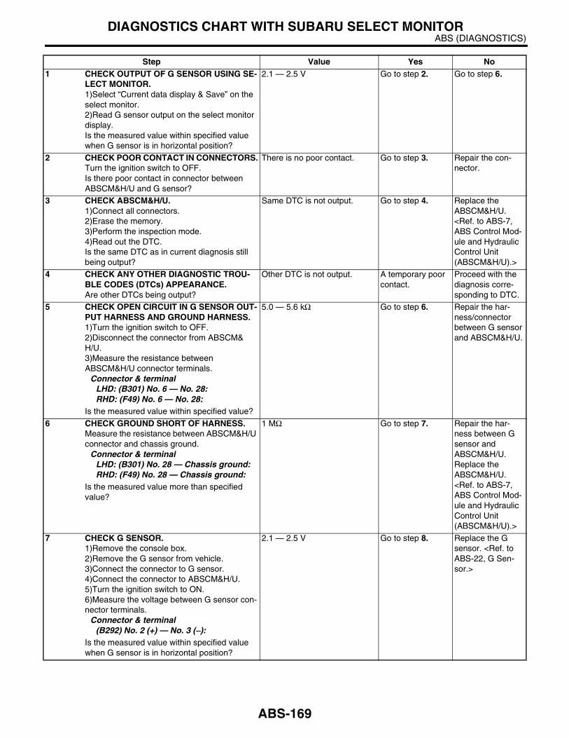
ABS (DIAGNOSTICS)DIAGNOSTICS CHART WITH SUBARU SELECT MONITOR
Step Value Yes No1 CHECK OUTPUT OF G SENSOR USING SE-
LECT MONITOR.1)Select “Current data display & Save” on the select monitor.2)Read G sensor output on the select monitor display.Is the measured value within specified value when G sensor is in horizontal position?
2.1 — 2.5 V Go to step 2. Go to step 6.
2 CHECK POOR CONTACT IN CONNECTORS.Turn the ignition switch to OFF.Is there poor contact in connector between ABSCM&H/U and G sensor?
There is no poor contact. Go to step 3. Repair the con-nector.
3 CHECK ABSCM&H/U.1)Connect all connectors.2)Erase the memory.3)Perform the inspection mode.4)Read out the DTC.Is the same DTC as in current diagnosis still being output?
Same DTC is not output. Go to step 4. Replace the ABSCM&H/U. <Ref. to ABS-7, ABS Control Mod-ule and Hydraulic Control Unit (ABSCM&H/U).>
4 CHECK ANY OTHER DIAGNOSTIC TROU-BLE CODES (DTCs) APPEARANCE.Are other DTCs being output?
Other DTC is not output. A temporary poor contact.
Proceed with the diagnosis corre-sponding to DTC.
5 CHECK OPEN CIRCUIT IN G SENSOR OUT-PUT HARNESS AND GROUND HARNESS.1)Turn the ignition switch to OFF.2)Disconnect the connector from ABSCM&H/U.3)Measure the resistance between ABSCM&H/U connector terminals.
Connector & terminalLHD: (B301) No. 6 — No. 28:RHD: (F49) No. 6 — No. 28:
Is the measured value within specified value?
5.0 — 5.6 kΩ Go to step 6. Repair the har-ness/connector between G sensor and ABSCM&H/U.
6 CHECK GROUND SHORT OF HARNESS.Measure the resistance between ABSCM&H/U connector and chassis ground.
Connector & terminalLHD: (B301) No. 28 — Chassis ground:RHD: (F49) No. 28 — Chassis ground:
Is the measured value more than specified value?
1 MΩ Go to step 7. Repair the har-ness between G sensor and ABSCM&H/U.Replace the ABSCM&H/U. <Ref. to ABS-7, ABS Control Mod-ule and Hydraulic Control Unit (ABSCM&H/U).>
7 CHECK G SENSOR.1)Remove the console box.2)Remove the G sensor from vehicle.3)Connect the connector to G sensor.4)Connect the connector to ABSCM&H/U.5)Turn the ignition switch to ON.6)Measure the voltage between G sensor con-nector terminals.
Connector & terminal(B292) No. 2 (+) — No. 3 (−−−−):
Is the measured value within specified value when G sensor is in horizontal position?
2.1 — 2.5 V Go to step 8. Replace the G sensor. <Ref. to ABS-22, G Sen-sor.>
ABS-169
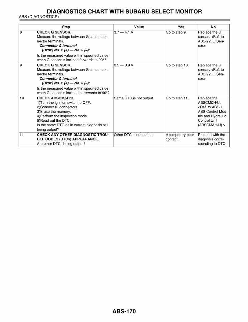
ABS (DIAGNOSTICS)DIAGNOSTICS CHART WITH SUBARU SELECT MONITOR
8 CHECK G SENSOR.Measure the voltage between G sensor con-nector terminals.
Connector & terminal(B292) No. 2 (+) — No. 3 (−−−−):
Is the measured value within specified value when G sensor is inclined forwards to 90°?
3.7 — 4.1 V Go to step 9. Replace the G sensor. <Ref. to ABS-22, G Sen-sor.>
9 CHECK G SENSOR.Measure the voltage between G sensor con-nector terminals.
Connector & terminal(B292) No. 2 (+) — No. 3 (−−−−):
Is the measured value within specified value when G sensor is inclined backwards to 90°?
0.5 — 0.9 V Go to step 10. Replace the G sensor. <Ref. to ABS-22, G Sen-sor.>
10 CHECK ABSCM&H/U.1)Turn the ignition switch to OFF.2)Connect all connectors.3)Erase the memory.4)Perform the inspection mode.5)Read out the DTC.Is the same DTC as in current diagnosis still being output?
Same DTC is not output. Go to step 11. Replace the ABSCM&H/U. <Ref. to ABS-7, ABS Control Mod-ule and Hydraulic Control Unit (ABSCM&H/U).>
11 CHECK ANY OTHER DIAGNOSTIC TROU-BLE CODES (DTCs) APPEARANCE.Are other DTCs being output?
Other DTC is not output. A temporary poor contact.
Proceed with the diagnosis corre-sponding to DTC.
Step Value Yes No
ABS-170

ABS (DIAGNOSTICS)DIAGNOSTICS CHART WITH SUBARU SELECT MONITOR
AH:DTC 56 — DETECTION OF G SENSOR STICK —
DIAGNOSIS:• Faulty G sensor output voltageTROUBLE SYMPTOM:• ABS does not operate.WIRING DIAGRAM:LHD MODEL
ABS00259
ABS CONTROL MODULE ANDHYDRAULIC CONTROL UNITB301
F103 B301
1 2 3 4 5 6 7 8 9 10 11 12 13 14 1516 17 18 19 20 21 22
27 28 29 30 3123 24 25 26
1 2 3 45 6 7 8
28
30 6 23
F103
B292
ABSG SENSOR
E
E
2
321
B292
1 2 3
SHIELD JOINTCONNECTOR
ABS-171

ABS (DIAGNOSTICS)DIAGNOSTICS CHART WITH SUBARU SELECT MONITOR
RHD MODEL
ABS00264
ABS CONTROL MODULE ANDHYDRAULIC CONTROL UNITF49
F48 F49
1 2 3 4 5 6 7 8 9 10 11 12 13 14 1516 17 18 19 20 21 22
27 28 29 30 3123 24 25 26
1 2 3 45 6 7 8
28
30 6 23
F48
B292
ABSG SENSOR
E
321
B292
1 2 3
SHIELD JOINTCONNECTOR
85
9
F45
B62
210 1
10 11 12 13 14 15 16 17 181 2 3 4 7 85 69
F45
Step Value Yes No1 CHECK ALL FOUR WHEELS FOR FREE
TURNING.Have the wheels been turned freely such as when vehicle is lifted up, or operated on a roll-ing road?
Wheels have not been turned freely.
Go to step 2. The ABS is nor-mal. Erase the DTC.
ABS-172

ABS (DIAGNOSTICS)DIAGNOSTICS CHART WITH SUBARU SELECT MONITOR
2 CHECK OUTPUT OF G SENSOR USING SE-LECT MONITOR.1)Select “Current data display & Save” on the select monitor.2)Read the select monitor display.Is the G sensor output on monitor display within specified value when the vehicle is in horizontal position?
2.1 — 2.5 V Go to step 3. Go to step 8.
3 CHECK OUTPUT OF G SENSOR USING SE-LECT MONITOR.1)Turn the ignition switch to OFF.2)Remove the console box.3)Remove the G sensor from vehicle. (Do not disconnect the connector.)4)Turn the ignition switch to ON.5)Select “Current data display & Save” on the select monitor.6)Read the select monitor display.Is the measured value within specified value when G sensor is inclined forwards to 90°?
3.7 — 4.1 V Go to step 4. Replace the G sensor. <Ref. to ABS-22, G Sen-sor.>
4 CHECK OUTPUT OF G SENSOR USING SE-LECT MONITOR.Read the select monitor display.Is the measured value within specified value when G sensor is inclined backwards to 90°?
0.5 — 0.9 V Go to step 5. Replace the G sensor. <Ref. to ABS-22, G Sen-sor.>
5 CHECK POOR CONTACT IN CONNECTORS.Turn the ignition switch to OFF.Is there poor contact in connector between ABSCM&H/U and G sensor?
There is no poor contact. Go to step 6. Repair the con-nector.
6 CHECK ABSCM&H/U.1)Connect all connectors.2)Erase the memory.3)Perform the inspection mode.4)Read out the DTC.Is the same DTC as in current diagnosis still being output?
Same DTC is not output. Go to step 7. Replace the ABSCM&H/U. <Ref. to ABS-7, ABS Control Mod-ule and Hydraulic Control Unit (ABSCM&H/U).>
7 CHECK ANY OTHER DIAGNOSTIC TROU-BLE CODES (DTCs) APPEARANCE.Are other DTCs being output?
Other DTC is not output. A temporary poor contact.
Proceed with the diagnosis corre-sponding to DTC.
8 CHECK OPEN CIRCUIT IN G SENSOR OUT-PUT HARNESS AND GROUND HARNESS.1)Turn the ignition switch to OFF.2)Disconnect the connector from ABSCM&H/U.3)Measure the resistance between ABSCM&H/U connector terminals.
Connector & terminalLHD: (B301) No. 6 — No. 28:RHD: (F49) No. 6 — No. 28:
Is the measured value within specified value?
5.0 — 5.6 kΩ Go to step 9. Repair the har-ness/connector between G sensor and ABSCM&H/U.
Step Value Yes No
ABS-173

ABS (DIAGNOSTICS)DIAGNOSTICS CHART WITH SUBARU SELECT MONITOR
9 CHECK G SENSOR.1)Remove the console box.2)Remove the G sensor from vehicle.3)Connect the connector to G sensor.4)Connect the connector to ABSCM&H/U.5)Turn the ignition switch to ON.6)Measure the voltage between G sensor con-nector terminals.
Connector & terminal(B292) No. 2 (+) — No. 3 (−−−−):
Is the measured value within specified value when G sensor is in horizontal position?
2.1 — 2.5 V Go to step 10. Replace the G sensor. <Ref. to ABS-22, G Sen-sor.>
10 CHECK G SENSOR.Measure the voltage between G sensor con-nector terminals.
Connector & terminal(B292) No. 2 (+) — No. 3 (−−−−):
Is the measured value within specified value when G sensor is inclined forwards to 90°?
3.7 — 4.1 V Go to step 11. Replace the G sensor. <Ref. to ABS-22, G Sen-sor.>
11 CHECK G SENSOR.Measure the voltage between G sensor con-nector terminals.
Connector & terminal(B292) No. 2 (+) — No. 3 (−−−−):
Is the measured value within specified value when G sensor is inclined backwards to 90°?
0.5 — 0.9 V Go to step 12. Replace the G sensor. <Ref. to ABS-22, G Sen-sor.>
12 CHECK ABSCM&H/U.1)Turn the ignition switch to OFF.2)Connect all connectors.3)Erase the memory.4)Perform the inspection mode.5)Read out the DTC.Is the same DTC as in current diagnosis still being output?
Same DTC is not output. Go to step 13. Replace the ABSCM&H/U. <Ref. to ABS-7, ABS Control Mod-ule and Hydraulic Control Unit (ABSCM&H/U).>
13 CHECK ANY OTHER DIAGNOSTIC TROU-BLE CODES (DTCs) APPEARANCE.Are other DTCs being output?
Other DTC is not output. A temporary poor contact.
Proceed with the diagnosis corre-sponding to DTC.
Step Value Yes No
ABS-174

ABS (DIAGNOSTICS)GENERAL DIAGNOSTICS TABLE
14.General Diagnostics TableA: INSPECTION
Symptom Probable faulty units/parts
Vehicle instability during braking
Vehicle pulls to either side.
• ABSCM&H/U (solenoid valve)• ABS sensor• Brake (caliper & piston, pads)• Wheel alignment• Tire specifications, tire wear and air pressures• Incorrect wiring or piping connections• Road surface (uneven, camber)
Vehicle spins.
• ABSCM&H/U (solenoid valve)• ABS sensor• Brake (pads)• Tire specifications, tire wear and air pressures• Incorrect wiring or piping connections
Poor braking
Long braking/stopping distance
• ABSCM&H/U (solenoid valve)• Brake (pads)• Air in brake line• Tire specifications, tire wear and air pressures• Incorrect wiring or piping connections
Wheel locks.• ABSCM&H/U (solenoid valve, motor)• ABS sensor• Incorrect wiring or piping connections
Brake dragging
• ABSCM&H/U (solenoid valve)• ABS sensor• Master cylinder• Brake (caliper & piston)• Parking brake• Axle & wheels• Brake pedal play
Long brake pedal stroke• Air in brake line• Brake pedal play
Vehicle pitching• Suspension play or fatigue (reduced damping)• Incorrect wiring or piping connections• Road surface (uneven)
Unstable or uneven braking
• ABSCM&H/U (solenoid valve)• ABS sensor• Brake (caliper & piston, pads)• Tire specifications, tire wear and air pressures• Incorrect wiring or piping connections• Road surface (uneven)
Vibration and/or noise (while driving on slippery roads)
Excessive pedal vibration• Incorrect wiring or piping connections• Road surface (uneven)
Noise from ABSCM&H/U• ABSCM&H/U (mount bushing)• ABS sensor• Brake piping
Noise from front of vehicle
• ABSCM&H/U (mount bushing)• ABS sensor• Master cylinder• Brake (caliper & piston, pads, rotor)• Brake piping• Brake booster & check valve• Suspension play or fatigue
Noise from rear of vehicle
• ABS sensor• Brake (caliper & piston, pads, rotor)• Parking brake• Brake piping• Suspension play or fatigue
ABS-175

ABS (DIAGNOSTICS)GENERAL DIAGNOSTICS TABLE
ABS-176


