

Angora AM50/AM30/AM10
Service Guide
PRINTED IN TAIWAN
Service guide files and updates are availableon the AIPG/CSD web; for more information,
please refer to http://csd.acer.com.tw
Downloaded from www.Manualslib.com manuals search engine

Revision HistoryPlease refer to the table below for the updates made on Angora AM50, AM30, and AM10 service guide.
Date Chapter Updates
Downloaded from www.Manualslib.com manuals search engine
CopyrightCopyright © 2007 by Acer Incorporated. All rights reserved. No part of this publication may be reproduced, transmitted, transcribed, stored in a retrieval system, or translated into any language or computer language, in any form or by any means, electronic, mechanical, magnetic, optical, chemical, manual or otherwise, without the prior written permission of Acer Incorporated.
DisclaimerThe information in this guide is subject to change without notice.
Acer Incorporated makes no representations or warranties, either expressed or implied, with respect to the contents hereof and specifically disclaims any warranties of merchantability or fitness for any particular purpose. Any Acer Incorporated software described in this manual is sold or licensed "as is". Should the programs prove defective following their purchase, the buyer (and not Acer Incorporated, its distributor, or its dealer) assumes the entire cost of all necessary servicing, repair, and any incidental or consequential damages resulting from any defect in the software.
Acer is a registered trademark of Acer Corporation.Intel is a registered trademark of Intel Corporation.Pentium 4 and Celeron are trademarks of Intel Corporation.Other brand and product names are trademarks and/or registered trademarks of their respective holders.
Downloaded from www.Manualslib.com manuals search engine
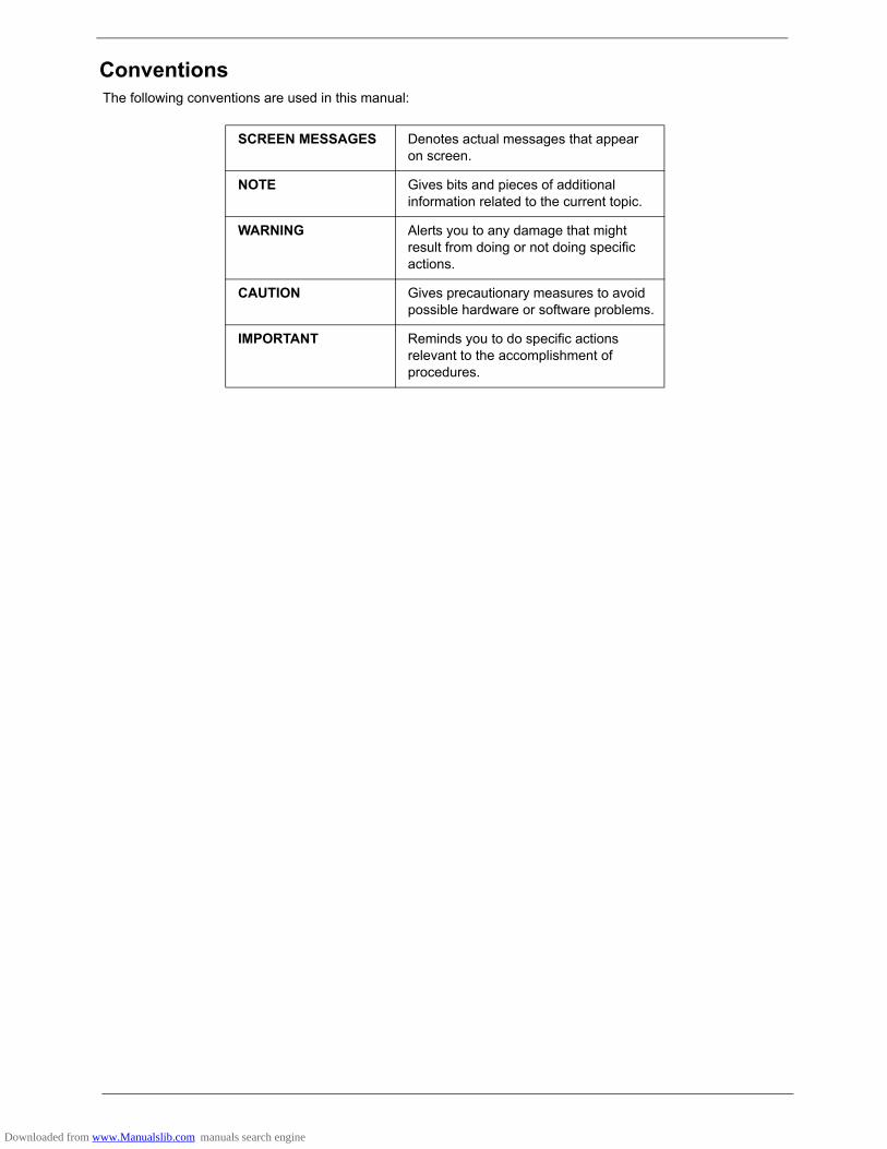
ConventionsThe following conventions are used in this manual:
SCREEN MESSAGES Denotes actual messages that appear on screen.
NOTE Gives bits and pieces of additional information related to the current topic.
WARNING Alerts you to any damage that might result from doing or not doing specific actions.
CAUTION Gives precautionary measures to avoid possible hardware or software problems.
IMPORTANT Reminds you to do specific actions relevant to the accomplishment of procedures.
Downloaded from www.Manualslib.com manuals search engine

PrefaceBefore using this information and the product it supports, please read the following general information.1. This Service Guide provides you with all technical information relating to the BASIC CONFIGURATION
decided for Acer's "global" product offering. To better fit local market requirements and enhance product competitiveness, your regional office MAY have decided to extend the functionality of a machine (e.g. add-on card, modem, or extra memory capability). These LOCALIZED FEATURES will NOT be covered in this generic service guide. In such cases, please contact your regional offices or the responsible personnel/channel to provide you with further technical details.
2. Please note WHEN ORDERING FRU PARTS, that you should check the most up-to-date information available on your regional web or channel. If, for whatever reason, a part number change is made, it will not be noted in the printed Service Guide. For ACER-AUTHORIZED SERVICE PROVIDERS, your Acer office may have a DIFFERENT part number code to those given in the FRU list of this printed Service Guide. You MUST use the list provided by your regional Acer office to order FRU parts for repair and service of customer machines.
Downloaded from www.Manualslib.com manuals search engine
i
System Specification 1Overview . . . . . . . . . . . . . . . . . . . . . . . . . . . . . . . . . . . . . . . . . . . . . . . . . . . . . . . . . . . .1
Size . . . . . . . . . . . . . . . . . . . . . . . . . . . . . . . . . . . . . . . . . . . . . . . . . . . . . . . . . . . .1Processor . . . . . . . . . . . . . . . . . . . . . . . . . . . . . . . . . . . . . . . . . . . . . . . . . . . . . . .1System Chipset . . . . . . . . . . . . . . . . . . . . . . . . . . . . . . . . . . . . . . . . . . . . . . . . . . .1Memory . . . . . . . . . . . . . . . . . . . . . . . . . . . . . . . . . . . . . . . . . . . . . . . . . . . . . . . . .1Onboard Graphics Solution . . . . . . . . . . . . . . . . . . . . . . . . . . . . . . . . . . . . . . . . . .1HDMI . . . . . . . . . . . . . . . . . . . . . . . . . . . . . . . . . . . . . . . . . . . . . . . . . . . . . . . . . . .1PCI Express/PCI Slots . . . . . . . . . . . . . . . . . . . . . . . . . . . . . . . . . . . . . . . . . . . . .1Floppy Disk Drive . . . . . . . . . . . . . . . . . . . . . . . . . . . . . . . . . . . . . . . . . . . . . . . . .1SATA Interface . . . . . . . . . . . . . . . . . . . . . . . . . . . . . . . . . . . . . . . . . . . . . . . . . . .1Audio . . . . . . . . . . . . . . . . . . . . . . . . . . . . . . . . . . . . . . . . . . . . . . . . . . . . . . . . . . .2LAN . . . . . . . . . . . . . . . . . . . . . . . . . . . . . . . . . . . . . . . . . . . . . . . . . . . . . . . . . . . .2USB . . . . . . . . . . . . . . . . . . . . . . . . . . . . . . . . . . . . . . . . . . . . . . . . . . . . . . . . . . . .21394a . . . . . . . . . . . . . . . . . . . . . . . . . . . . . . . . . . . . . . . . . . . . . . . . . . . . . . . . . .2Buzzer . . . . . . . . . . . . . . . . . . . . . . . . . . . . . . . . . . . . . . . . . . . . . . . . . . . . . . . . . .2Front Panel I/O Header . . . . . . . . . . . . . . . . . . . . . . . . . . . . . . . . . . . . . . . . . . . . .2CIR & IR Blaster . . . . . . . . . . . . . . . . . . . . . . . . . . . . . . . . . . . . . . . . . . . . . . . . . .2Onboard Connectors . . . . . . . . . . . . . . . . . . . . . . . . . . . . . . . . . . . . . . . . . . . . . . .2
Block Diagram . . . . . . . . . . . . . . . . . . . . . . . . . . . . . . . . . . . . . . . . . . . . . . . . . . . . . . .4Angora AM50 . . . . . . . . . . . . . . . . . . . . . . . . . . . . . . . . . . . . . . . . . . . . . . . . . . . . . . . .5
Front Panel . . . . . . . . . . . . . . . . . . . . . . . . . . . . . . . . . . . . . . . . . . . . . . . . . . . . . .5Rear Panel . . . . . . . . . . . . . . . . . . . . . . . . . . . . . . . . . . . . . . . . . . . . . . . . . . . . . .6
Angora AM30 . . . . . . . . . . . . . . . . . . . . . . . . . . . . . . . . . . . . . . . . . . . . . . . . . . . . . . . .7Front Panel . . . . . . . . . . . . . . . . . . . . . . . . . . . . . . . . . . . . . . . . . . . . . . . . . . . . . .7Rear Panel . . . . . . . . . . . . . . . . . . . . . . . . . . . . . . . . . . . . . . . . . . . . . . . . . . . . . .8
Angora AM10 . . . . . . . . . . . . . . . . . . . . . . . . . . . . . . . . . . . . . . . . . . . . . . . . . . . . . . . .9Front Panel . . . . . . . . . . . . . . . . . . . . . . . . . . . . . . . . . . . . . . . . . . . . . . . . . . . . . .9Rear Panel . . . . . . . . . . . . . . . . . . . . . . . . . . . . . . . . . . . . . . . . . . . . . . . . . . . . .10
Acer Empowering Technology . . . . . . . . . . . . . . . . . . . . . . . . . . . . . . . . . . . . . . . . . .11Empowering Technology password . . . . . . . . . . . . . . . . . . . . . . . . . . . . . . . . . .11Acer eRecovery Management . . . . . . . . . . . . . . . . . . . . . . . . . . . . . . . . . . . . . .11Acer eDataSecurity Management . . . . . . . . . . . . . . . . . . . . . . . . . . . . . . . . . . . .12Acer ePerformance Management . . . . . . . . . . . . . . . . . . . . . . . . . . . . . . . . . . . .14Acer eRecovery . . . . . . . . . . . . . . . . . . . . . . . . . . . . . . . . . . . . . . . . . . . . . . . . .15Create Backup . . . . . . . . . . . . . . . . . . . . . . . . . . . . . . . . . . . . . . . . . . . . . . . . . .15Restore from Backup . . . . . . . . . . . . . . . . . . . . . . . . . . . . . . . . . . . . . . . . . . . . .15Create Factory Default Image CD . . . . . . . . . . . . . . . . . . . . . . . . . . . . . . . . . . . .15Re-install Bundled Software without CD . . . . . . . . . . . . . . . . . . . . . . . . . . . . . . .15Change Password . . . . . . . . . . . . . . . . . . . . . . . . . . . . . . . . . . . . . . . . . . . . . . . .16
Acer Disc-to-Disc Recovery . . . . . . . . . . . . . . . . . . . . . . . . . . . . . . . . . . . . . . . . . . . .17Restore without a Recovery CD . . . . . . . . . . . . . . . . . . . . . . . . . . . . . . . . . . . . .17Multilingual Operating System Installation . . . . . . . . . . . . . . . . . . . . . . . . . . . . .17
Hardware Specification and Configuration . . . . . . . . . . . . . . . . . . . . . . . . . . . . . . . . .18Processor . . . . . . . . . . . . . . . . . . . . . . . . . . . . . . . . . . . . . . . . . . . . . . . . . . . . . .18System Main Chipset . . . . . . . . . . . . . . . . . . . . . . . . . . . . . . . . . . . . . . . . . . . . .18North Bridge . . . . . . . . . . . . . . . . . . . . . . . . . . . . . . . . . . . . . . . . . . . . . . . . . . . .18South Bridge . . . . . . . . . . . . . . . . . . . . . . . . . . . . . . . . . . . . . . . . . . . . . . . . . . . .19Wake-up Event Specification (Default Setting in BIOS) . . . . . . . . . . . . . . . . . . .19Front Panel LED States . . . . . . . . . . . . . . . . . . . . . . . . . . . . . . . . . . . . . . . . . . .20System Memory . . . . . . . . . . . . . . . . . . . . . . . . . . . . . . . . . . . . . . . . . . . . . . . . .20Super I/O . . . . . . . . . . . . . . . . . . . . . . . . . . . . . . . . . . . . . . . . . . . . . . . . . . . . . . .20
Table of Contents
Downloaded from www.Manualslib.com manuals search engine
ii
USB Interface . . . . . . . . . . . . . . . . . . . . . . . . . . . . . . . . . . . . . . . . . . . . . . . . . . .20Audio Interface . . . . . . . . . . . . . . . . . . . . . . . . . . . . . . . . . . . . . . . . . . . . . . . . . .211394 Interface . . . . . . . . . . . . . . . . . . . . . . . . . . . . . . . . . . . . . . . . . . . . . . . . . . .21Hardware Monitor Function . . . . . . . . . . . . . . . . . . . . . . . . . . . . . . . . . . . . . . . . .21BIOS . . . . . . . . . . . . . . . . . . . . . . . . . . . . . . . . . . . . . . . . . . . . . . . . . . . . . . . . . .22BIOS Hotkey List . . . . . . . . . . . . . . . . . . . . . . . . . . . . . . . . . . . . . . . . . . . . . . . . .22Environment Requirements . . . . . . . . . . . . . . . . . . . . . . . . . . . . . . . . . . . . . . . .22
Power Management Function (ACPI Support Function) . . . . . . . . . . . . . . . . . . . . . . .23Device Standby Mode . . . . . . . . . . . . . . . . . . . . . . . . . . . . . . . . . . . . . . . . . . . . .23Global Standby Mode . . . . . . . . . . . . . . . . . . . . . . . . . . . . . . . . . . . . . . . . . . . . .23Suspend Mode . . . . . . . . . . . . . . . . . . . . . . . . . . . . . . . . . . . . . . . . . . . . . . . . . .23ACPI . . . . . . . . . . . . . . . . . . . . . . . . . . . . . . . . . . . . . . . . . . . . . . . . . . . . . . . . . .23
Setup Utility 25About the Setup Utility . . . . . . . . . . . . . . . . . . . . . . . . . . . . . . . . . . . . . . . . . . . . . . . .25
Control Keys . . . . . . . . . . . . . . . . . . . . . . . . . . . . . . . . . . . . . . . . . . . . . . . . . . . .25Entering the Setup Utility . . . . . . . . . . . . . . . . . . . . . . . . . . . . . . . . . . . . . . . . . . . . . .26Product Information . . . . . . . . . . . . . . . . . . . . . . . . . . . . . . . . . . . . . . . . . . . . . . . . . .27Standard CMOS Features . . . . . . . . . . . . . . . . . . . . . . . . . . . . . . . . . . . . . . . . . . . . .28
Date and Time . . . . . . . . . . . . . . . . . . . . . . . . . . . . . . . . . . . . . . . . . . . . . . . . . .28SATA Devices . . . . . . . . . . . . . . . . . . . . . . . . . . . . . . . . . . . . . . . . . . . . . . . . . . .28Drive A . . . . . . . . . . . . . . . . . . . . . . . . . . . . . . . . . . . . . . . . . . . . . . . . . . . . . . . .28Halt On . . . . . . . . . . . . . . . . . . . . . . . . . . . . . . . . . . . . . . . . . . . . . . . . . . . . . . . .28Base Memory, Extended Memory, and Total Memory . . . . . . . . . . . . . . . . . . . .28
Advanced BIOS Features . . . . . . . . . . . . . . . . . . . . . . . . . . . . . . . . . . . . . . . . . . . . . .29Virus Warning . . . . . . . . . . . . . . . . . . . . . . . . . . . . . . . . . . . . . . . . . . . . . . . . . . .29CPU Internal Cache/External Cache . . . . . . . . . . . . . . . . . . . . . . . . . . . . . . . . .29Quick Power On Self Test . . . . . . . . . . . . . . . . . . . . . . . . . . . . . . . . . . . . . . . . . .30First / Second / Third Boot Device . . . . . . . . . . . . . . . . . . . . . . . . . . . . . . . . . . .30Boot Other Device . . . . . . . . . . . . . . . . . . . . . . . . . . . . . . . . . . . . . . . . . . . . . . . .30Boot Up Floppy Seek . . . . . . . . . . . . . . . . . . . . . . . . . . . . . . . . . . . . . . . . . . . . .30Boot Up NumLock Status . . . . . . . . . . . . . . . . . . . . . . . . . . . . . . . . . . . . . . . . . .30Gate A20 Option . . . . . . . . . . . . . . . . . . . . . . . . . . . . . . . . . . . . . . . . . . . . . . . . .30Typematic Rate Setting . . . . . . . . . . . . . . . . . . . . . . . . . . . . . . . . . . . . . . . . . . . .30Security Option . . . . . . . . . . . . . . . . . . . . . . . . . . . . . . . . . . . . . . . . . . . . . . . . . .30APIC Mode 30MPS Version Control For OS . . . . . . . . . . . . . . . . . . . . . . . . . . . . . . . . . . . . . . .30OS Select for DRAM > 64 MB . . . . . . . . . . . . . . . . . . . . . . . . . . . . . . . . . . . . . . .30HDD S.M.A.R.T Capability . . . . . . . . . . . . . . . . . . . . . . . . . . . . . . . . . . . . . . . . .31Silent Boot . . . . . . . . . . . . . . . . . . . . . . . . . . . . . . . . . . . . . . . . . . . . . . . . . . . . . .31Small Logo (EPA) Show . . . . . . . . . . . . . . . . . . . . . . . . . . . . . . . . . . . . . . . . . . .31Configuration Table . . . . . . . . . . . . . . . . . . . . . . . . . . . . . . . . . . . . . . . . . . . . . . .31Bootblock Write Protect . . . . . . . . . . . . . . . . . . . . . . . . . . . . . . . . . . . . . . . . . . .31Hard Disk Boot Priority . . . . . . . . . . . . . . . . . . . . . . . . . . . . . . . . . . . . . . . . . . . .32
Advanced Chipset Features . . . . . . . . . . . . . . . . . . . . . . . . . . . . . . . . . . . . . . . . . . . .33UMA Frame Buffer Size . . . . . . . . . . . . . . . . . . . . . . . . . . . . . . . . . . . . . . . . . . .33Memory Hole . . . . . . . . . . . . . . . . . . . . . . . . . . . . . . . . . . . . . . . . . . . . . . . . . . . .33System BIOS Cacheable . . . . . . . . . . . . . . . . . . . . . . . . . . . . . . . . . . . . . . . . . .33
Integrated Peripherals . . . . . . . . . . . . . . . . . . . . . . . . . . . . . . . . . . . . . . . . . . . . . . . .34South OnChip IDE Device . . . . . . . . . . . . . . . . . . . . . . . . . . . . . . . . . . . . . . . . .34South OnChip PCI Device . . . . . . . . . . . . . . . . . . . . . . . . . . . . . . . . . . . . . . . . .34Super IO Device . . . . . . . . . . . . . . . . . . . . . . . . . . . . . . . . . . . . . . . . . . . . . . . . .34Init Display First . . . . . . . . . . . . . . . . . . . . . . . . . . . . . . . . . . . . . . . . . . . . . . . . .34South OnChip IDE Device . . . . . . . . . . . . . . . . . . . . . . . . . . . . . . . . . . . . . . . . .35IDE DMA Transfer Access . . . . . . . . . . . . . . . . . . . . . . . . . . . . . . . . . . . . . . . . .35
Downloaded from www.Manualslib.com manuals search engine

iii
OnChip IDE Channel . . . . . . . . . . . . . . . . . . . . . . . . . . . . . . . . . . . . . . . . . . . . .35IDE Primary/Secondary Master/Slave PIO . . . . . . . . . . . . . . . . . . . . . . . . . . . . .35IDE Primary/Secondary Master/Slave UltraDMA . . . . . . . . . . . . . . . . . . . . . . . .35IDE HDD Block Mode . . . . . . . . . . . . . . . . . . . . . . . . . . . . . . . . . . . . . . . . . . . . .35South OnChip PCI Device . . . . . . . . . . . . . . . . . . . . . . . . . . . . . . . . . . . . . . . . .36ATI Azalia Audio . . . . . . . . . . . . . . . . . . . . . . . . . . . . . . . . . . . . . . . . . . . . . . . . .36ATI SATA Controller . . . . . . . . . . . . . . . . . . . . . . . . . . . . . . . . . . . . . . . . . . . . . .36ATI SATA Type . . . . . . . . . . . . . . . . . . . . . . . . . . . . . . . . . . . . . . . . . . . . . . . . . .36USB EHCI Controller . . . . . . . . . . . . . . . . . . . . . . . . . . . . . . . . . . . . . . . . . . . . .36OnChip USB Controller . . . . . . . . . . . . . . . . . . . . . . . . . . . . . . . . . . . . . . . . . . . .37OnChip USB KBC Controller . . . . . . . . . . . . . . . . . . . . . . . . . . . . . . . . . . . . . . .37USB Mouse Support . . . . . . . . . . . . . . . . . . . . . . . . . . . . . . . . . . . . . . . . . . . . . .37Onboard LAN Controller . . . . . . . . . . . . . . . . . . . . . . . . . . . . . . . . . . . . . . . . . . .37Onboard Lan Boot ROM . . . . . . . . . . . . . . . . . . . . . . . . . . . . . . . . . . . . . . . . . . .37Onboard 1394 Controller . . . . . . . . . . . . . . . . . . . . . . . . . . . . . . . . . . . . . . . . . .37Super IO Device . . . . . . . . . . . . . . . . . . . . . . . . . . . . . . . . . . . . . . . . . . . . . . . . .38Onboard FDC Controller . . . . . . . . . . . . . . . . . . . . . . . . . . . . . . . . . . . . . . . . . . .38Onboard Serial Port 1 . . . . . . . . . . . . . . . . . . . . . . . . . . . . . . . . . . . . . . . . . . . . .38Onboard Serial Port 2 . . . . . . . . . . . . . . . . . . . . . . . . . . . . . . . . . . . . . . . . . . . . .38UART Mode Select . . . . . . . . . . . . . . . . . . . . . . . . . . . . . . . . . . . . . . . . . . . . . . .38UR2 Duplex Mode . . . . . . . . . . . . . . . . . . . . . . . . . . . . . . . . . . . . . . . . . . . . . . . .38Onboard Parallel Port . . . . . . . . . . . . . . . . . . . . . . . . . . . . . . . . . . . . . . . . . . . . .39Parallel Port Mode . . . . . . . . . . . . . . . . . . . . . . . . . . . . . . . . . . . . . . . . . . . . . . .39ECP Mode Use DMA . . . . . . . . . . . . . . . . . . . . . . . . . . . . . . . . . . . . . . . . . . . . .39
Power Management Setup . . . . . . . . . . . . . . . . . . . . . . . . . . . . . . . . . . . . . . . . . . . . .40ACPI Function . . . . . . . . . . . . . . . . . . . . . . . . . . . . . . . . . . . . . . . . . . . . . . . . . . .40ACPI Suspend Type . . . . . . . . . . . . . . . . . . . . . . . . . . . . . . . . . . . . . . . . . . . . . .40CS2 Disable/Enable . . . . . . . . . . . . . . . . . . . . . . . . . . . . . . . . . . . . . . . . . . . . . .41Power Management Option . . . . . . . . . . . . . . . . . . . . . . . . . . . . . . . . . . . . . . . .41Video Off Option . . . . . . . . . . . . . . . . . . . . . . . . . . . . . . . . . . . . . . . . . . . . . . . . .41Video Off Method . . . . . . . . . . . . . . . . . . . . . . . . . . . . . . . . . . . . . . . . . . . . . . . .41Soft-Off by PWRBTN . . . . . . . . . . . . . . . . . . . . . . . . . . . . . . . . . . . . . . . . . . . . .41Power On By PCI Card . . . . . . . . . . . . . . . . . . . . . . . . . . . . . . . . . . . . . . . . . . . .41USB Wakeup From S1/S2 . . . . . . . . . . . . . . . . . . . . . . . . . . . . . . . . . . . . . . . . .41USB Wakeup From S4 . . . . . . . . . . . . . . . . . . . . . . . . . . . . . . . . . . . . . . . . . . . .41PS2 KB/MS Wakeup From S1/S2 . . . . . . . . . . . . . . . . . . . . . . . . . . . . . . . . . . . .41Wakeup By LAN . . . . . . . . . . . . . . . . . . . . . . . . . . . . . . . . . . . . . . . . . . . . . . . . .41HPET Support . . . . . . . . . . . . . . . . . . . . . . . . . . . . . . . . . . . . . . . . . . . . . . . . . . .41PWRON After PWR-Fail . . . . . . . . . . . . . . . . . . . . . . . . . . . . . . . . . . . . . . . . . . .41RTC Alarm Resume . . . . . . . . . . . . . . . . . . . . . . . . . . . . . . . . . . . . . . . . . . . . . .42
PnP/PCI Configurations . . . . . . . . . . . . . . . . . . . . . . . . . . . . . . . . . . . . . . . . . . . . . . .43Reset Configuration Data . . . . . . . . . . . . . . . . . . . . . . . . . . . . . . . . . . . . . . . . . .43Resources Controlled By . . . . . . . . . . . . . . . . . . . . . . . . . . . . . . . . . . . . . . . . . .43PCI/VGA Palette Snoop . . . . . . . . . . . . . . . . . . . . . . . . . . . . . . . . . . . . . . . . . . .43Assign IRQ For VGA . . . . . . . . . . . . . . . . . . . . . . . . . . . . . . . . . . . . . . . . . . . . . .43Assign IRQ for USB . . . . . . . . . . . . . . . . . . . . . . . . . . . . . . . . . . . . . . . . . . . . . .44PCI Latency Timer (CLK) . . . . . . . . . . . . . . . . . . . . . . . . . . . . . . . . . . . . . . . . . .44Maximum Payload Size . . . . . . . . . . . . . . . . . . . . . . . . . . . . . . . . . . . . . . . . . . .44
PC Health Status . . . . . . . . . . . . . . . . . . . . . . . . . . . . . . . . . . . . . . . . . . . . . . . . . . . .45CPU Shut Down Temperature . . . . . . . . . . . . . . . . . . . . . . . . . . . . . . . . . . . . . .45
Frequency & Voltage Control . . . . . . . . . . . . . . . . . . . . . . . . . . . . . . . . . . . . . . . . . . .47Spread Spectrum . . . . . . . . . . . . . . . . . . . . . . . . . . . . . . . . . . . . . . . . . . . . . . . .47SB600 Spread Spectrum . . . . . . . . . . . . . . . . . . . . . . . . . . . . . . . . . . . . . . . . . .47
Load Optimized Defaults . . . . . . . . . . . . . . . . . . . . . . . . . . . . . . . . . . . . . . . . . . . . . .48Set Supervisor Password . . . . . . . . . . . . . . . . . . . . . . . . . . . . . . . . . . . . . . . . . . . . . .49
Downloaded from www.Manualslib.com manuals search engine

iv
Enter Password . . . . . . . . . . . . . . . . . . . . . . . . . . . . . . . . . . . . . . . . . . . . . . . . . .49Save and Exit Setup . . . . . . . . . . . . . . . . . . . . . . . . . . . . . . . . . . . . . . . . . . . . . . . . . .50Exit without Saving . . . . . . . . . . . . . . . . . . . . . . . . . . . . . . . . . . . . . . . . . . . . . . . . . . .51
Machine Disassembly and Replacement 53General Information . . . . . . . . . . . . . . . . . . . . . . . . . . . . . . . . . . . . . . . . . . . . . . . . . .53
Before You Begin . . . . . . . . . . . . . . . . . . . . . . . . . . . . . . . . . . . . . . . . . . . . . . . .53Angora AM50/30/10 Procedures . . . . . . . . . . . . . . . . . . . . . . . . . . . . . . . . . . . . . . . .54
Disassembly Procedure . . . . . . . . . . . . . . . . . . . . . . . . . . . . . . . . . . . . . . . . . . .54Reassembly Procedure . . . . . . . . . . . . . . . . . . . . . . . . . . . . . . . . . . . . . . . . . . . .61
Troubleshooting 69Jumper and Connector Information 71
Introduction to Connectors . . . . . . . . . . . . . . . . . . . . . . . . . . . . . . . . . . . . . . . . . . . . .71Main Board Placement . . . . . . . . . . . . . . . . . . . . . . . . . . . . . . . . . . . . . . . . . . . .71Connectors. . . . . . . . . . . . . . . . . . . . . . . . . . . . . . . . . . . . . . . . . . . . . . . . . . . . . .73Jumpers . . . . . . . . . . . . . . . . . . . . . . . . . . . . . . . . . . . . . . . . . . . . . . . . . . . . . . .77
FRU (Field Replaceable Unit) List 83Angora AM50 Exploded Diagram . . . . . . . . . . . . . . . . . . . . . . . . . . . . . . . . . . . . . . . .84Angora AM30 Exploded Diagram . . . . . . . . . . . . . . . . . . . . . . . . . . . . . . . . . . . . . . . .85Angora AM10 Exploded Diagram . . . . . . . . . . . . . . . . . . . . . . . . . . . . . . . . . . . . . . . .86
Downloaded from www.Manualslib.com manuals search engine
Chapter 1 1
OverviewSize
• 240x240mm (9.6"x9.6") 4 Layers
Processor• Socket type: AMD AM2 socket• Socket quantity: one• Processor type: Sempron-D, Athlon64, Athlon64+
System Chipset• North bridge: ATI RS690• South bridge: ATI SB600• Super I/O: ITE8718F with Hardware monitor
Memory• Dual Channel DDR2 667/533/400,Unbuffered DIMM• Support 4 DDRII DIMM (8 GB Maximum capacity)
Onboard Graphics Solution• ATI RS690 on-die graphic solution (ATI Radeon® X700-based graphic core)
• ATI AVIVO technology support• Multiple display features support• One D-Sub VGA port on the rear side• One HDMI port on the rear side (A14)• SDVO interface which supports hot plug detection
HDMI• With HDCP solution• Meets HDMI 1.2a specification
PCI Express/PCI Slots• One PCI Express x16 slot• One PCI Express x1 slot• Two PCI slots
Floppy Disk Drive• One slot, 1.44MB/3 mode 3.5” devices support
SATA Interface• Two separate controllers with integrated SATA 2 (Gen1 and Gen2) PHYs• Each controller supports two drives in master mode for a total of four
System Specification
Chapter 1
Downloaded from www.Manualslib.com manuals search engine
2 Chapter 1
• Compliant with ATA/ATAPI-7 Volume 3 Serial ATA standards• High speed, low voltage, low pin count• Each controller supports dual channel SATA 2• 3.0 Gb/s per direction per channel• Supports power-down capabilities
Audio• Realtek ALC888-GR, colay with ALC883
LAN• Marvell 88E8056, Gb PHY featuring:
• 10/100/1000BASE-T IEEE 802.3 compliant• Two-Wire Serial Interface (TWSI) for VPD• 2.5GHz Signaling,x1 link width, width strapped on reset• Support of up to eight outstanding NP requests as a master
USB• X10 USB2.0/1.1(Rear 4 ports, Front 6ports)
1394a• 1394 header x 1 and Back I/O *1 (TSB43AB23PDTG4 2-port)
Buzzer• One onboard buzzer
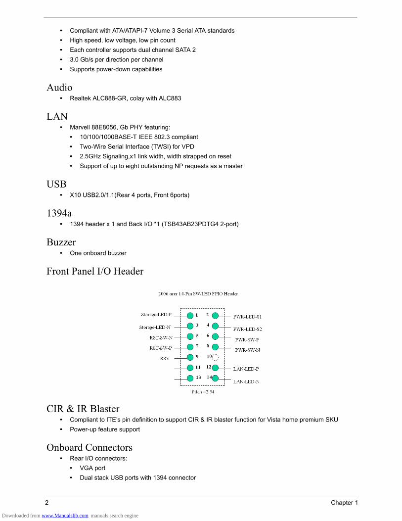
Front Panel I/O Header
CIR & IR Blaster• Compliant to ITE’s pin definition to support CIR & IR blaster function for Vista home premium SKU• Power-up feature support
Onboard Connectors• Rear I/O connectors:
• VGA port• Dual stack USB ports with 1394 connector
Downloaded from www.Manualslib.com manuals search engine
Chapter 1 3
• Dual Stack USB ports with RJ-45 connector• Vertical Audio connector with 6 JACKS• DVI-I port• HDMI port• PS2 port• Print port
• Onboard connectors:• One CPU socket• Four DDR2 memory sockets• One PCI Express x16 slot• One PCI Express x1 slot• Two PCI slots• One FDD slot• One PATA slot• Four SATAII IDE connectors• Three 2*5 pin USB headers, compliant to Intel FPIO standard specification• One 2*5 pin front audio header, compliant to Intel FPIO standard specification• One 2*5 pin serial port connector• One 1*4 pin AUX-In connector• One 4-pin CPU fan connector• One 3-pin system fan connector with linear circuit• One 24-pin + 4-pin ATX interface PS3/PS2 SPS connector• One 2*7 pin front panel I/O header• One 2*5 pin 1394 header
Downloaded from www.Manualslib.com manuals search engine
4 Chapter 1
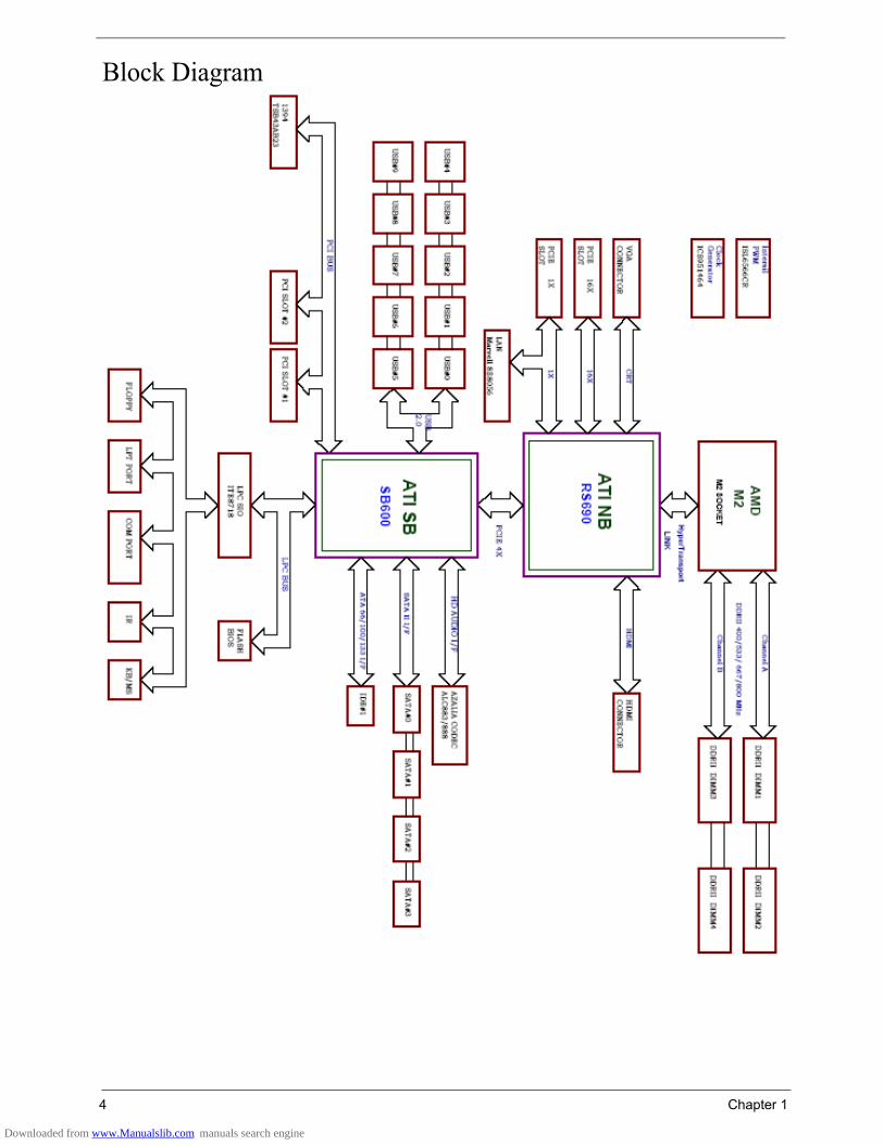
Block Diagram
Downloaded from www.Manualslib.com manuals search engine

Chapter 1 5
Angora AM50Front Panel
# Description1 ODD Door
2 Slide Door
3 LAN LED
4 HDD LED
5 Power Button
6 USB Port
7 MIC Phone
8 Speaker Out
Downloaded from www.Manualslib.com manuals search engine
6 Chapter 1
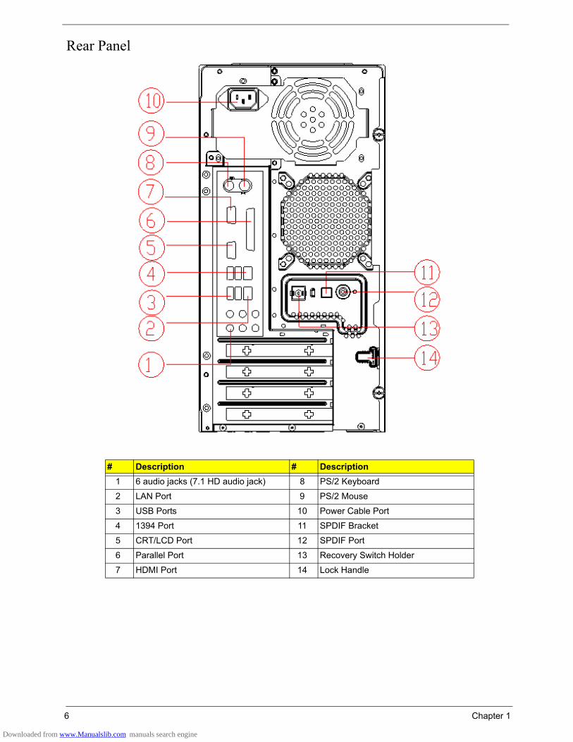
Rear Panel
# Description # Description1 6 audio jacks (7.1 HD audio jack) 8 PS/2 Keyboard
2 LAN Port 9 PS/2 Mouse
3 USB Ports 10 Power Cable Port
4 1394 Port 11 SPDIF Bracket
5 CRT/LCD Port 12 SPDIF Port
6 Parallel Port 13 Recovery Switch Holder
7 HDMI Port 14 Lock Handle
Downloaded from www.Manualslib.com manuals search engine

Chapter 1 7
Angora AM30Front Panel
# Description1 Optical Device
2 3.5” Device
3 LAN LED
4 HDD LED
5 Power Button
6 USB Port
7 MIC Phone
8 Speaker Out
Downloaded from www.Manualslib.com manuals search engine

8 Chapter 1
Rear Panel
# Description # Description1 6 audio jacks (7.1 HD audio jack) 8 PS/2 Keyboard
2 LAN Port 9 PS/2 Mouse
3 USB Ports 10 Power Cable Port
4 1394 Port 11 SPDIF Bracket
5 CRT/LCD Port 12 SPDIF Port
6 Parallel Port 13 Recovery Switch Holder
7 HDMI Port 14 Lock Handle
Downloaded from www.Manualslib.com manuals search engine
Chapter 1 9
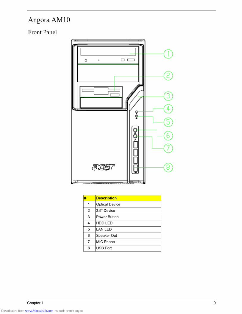
Angora AM10Front Panel
# Description1 Optical Device
2 3.5” Device
3 Power Button
4 HDD LED
5 LAN LED
6 Speaker Out
7 MIC Phone
8 USB Port
Downloaded from www.Manualslib.com manuals search engine

10 Chapter 1
Rear Panel
# Description # Description1 6 audio jacks (7.1 HD audio jack) 8 PS/2 Keyboard
2 LAN Port 9 PS/2 Mouse
3 USB Ports 10 Power Cable Port
4 1394 Port 11 SPDIF Bracket
5 CRT/LCD Port 12 SPDIF Port
6 Parallel Port 13 Recovery Switch Holder
7 HDMI Port 14 Lock Handle
Downloaded from www.Manualslib.com manuals search engine

Chapter 1 11
Acer Empowering TechnologyAcer’s innovative Empowering Technology makes it easy for you to access frequently used functions and manage your new Acer notebook. It features the following handy utilities:
• Acer eRecovery Management backs up and recovers data flexibly, reliably and completely.• Acer eDataSecurity Management protects data with passwords and advanced encryption algorithms.• Acer ePerformance Management improves system performance by optimizing disk space, memory and
registry settings.
For more information, press the key to launch the Empowering Technology menu, then click on the appropriate utility and select the Help or Tutorial function.
Empowering Technology passwordBefore using Acer eRecovery Management, you must initialize the Empowering Technology password. Right click on the Empowering Technology toolbar and select Password Setup to do so. If you do not initialize the Empowering Technology password, you will be prompted to do so when running Acer eRecovery Management for the first time.
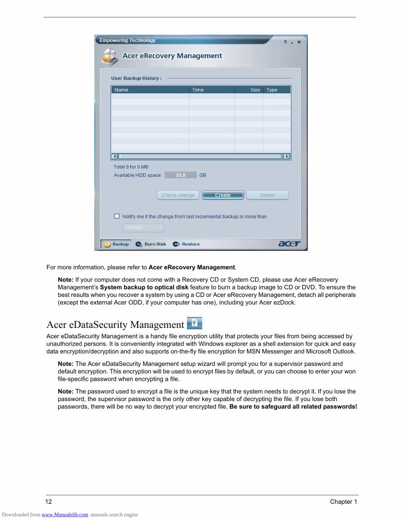
Acer eRecovery Management Acer eRecovery Management is a powerful utility that does away with the need for recovery disks provided by the manufacturer. The Acer eRecovery Management utility supports Microsoft Windows XP Home Service Pack 2, Microsoft Windows XP Media Center Edition Wallop 2, Microsoft Windows Vista Home Basic, Premium, Business, and Ultimate. The Acer eRecovery Management utility occupies space in a hidden partition on your system’s HDD. User-created backups are stored on D:\ drive.
Acer eRecovery Management provides you with:• Password protection• Recovery of applications and drivers• Image/data backup:
• Back up to HDD (set recovery point)• Back up to CD/DVD
• Image/data recovery tools• Recovery from a hidden partition (factory defaults)• Recovery from the HDD (most recent user-defined recovery point)• Recovery from CD/DVD
Downloaded from www.Manualslib.com manuals search engine
12 Chapter 1
For more information, please refer to Acer eRecovery Management.
Note: If your computer does not come with a Recovery CD or System CD, please use Acer eRecovery Management’s System backup to optical disk feature to burn a backup image to CD or DVD. To ensure the best results when you recover a system by using a CD or Acer eRecovery Management, detach all peripherals (except the external Acer ODD, if your computer has one), including your Acer ezDock.
Acer eDataSecurity Management Acer eDataSecurity Management is a handy file encryption utility that protects your files from being accessed by unauthorized persons. It is conveniently integrated with Windows explorer as a shell extension for quick and easy data encryption/decryption and also supports on-the-fly file encryption for MSN Messenger and Microsoft Outlook.
Note: The Acer eDataSecurity Management setup wizard will prompt you for a supervisor password and default encryption. This encryption will be used to encrypt files by default, or you can choose to enter your won file-specific password when encrypting a file.
Note: The password used to encrypt a file is the unique key that the system needs to decrypt it. If you lose the password, the supervisor password is the only other key capable of decrypting the file. If you lose both passwords, there will be no way to decrypt your encrypted file. Be sure to safeguard all related passwords!
Downloaded from www.Manualslib.com manuals search engine

14 Chapter 1
Acer ePerformance Management Acer ePerformance Management is a system optimization tool that boosts the performance of your Acer notebook. It provides and expresses optimization method to release unused memory and disk space quickly. The user can also enable advanced options for full control over the following option:
• Memory optimization: to releases unused memory and check usage• Disk optimization: to remove unneeded items and files• Speed optimization: to improve the usability and performance of your Windows XP system
For more information, please refer to Acer eRecovery Management.
Note: If your computer does not come with a Recovery CD or System CD, please use Acer eRecovery Management’s System backup to optical disk feature to burn a backup image to CD or DVD. To ensure the best results when recovering your system using a CD or Acer eRecovery Management, detach all peripherals (except the external Acer ODD, if your computer has one), including your Acer ezDock.
Downloaded from www.Manualslib.com manuals search engine
Chapter 1 15
Acer eRecoveryAcer eRecovery is a tool to quickly backup and restore the system. Users can create and save a backup of the current system configuration to hard drive, CD, or DVD. Acer eRecovery consists of the following functions:1. Create backup2. Restore from backup3. Create factory default image CD4. Re-install bundled software without CD5. Change Acer eRecovery password
Create BackupUsers can create and save backup images to hard drive, CD, or DVD. Please follow the steps below to create backup.1. Boot to Windows XP.2. Press <Alt> + <F10> to open the Acer eRecovery utility.3. Enter the password to proceed. The default password is six zeros.4. In the Acer eRecovery window, select Recovery settings and click Next.5. In the Recovery settings window, select Backup snapshot image and click Next.6. Select the backup method:
• Use Backup to HDD to store the backup disc image on drive D:\• Backup to optical device to store the backup disc image on CD or DVD. This option is only available on
systems that include an optical disc burner.7. After choosing the backup method, click Next.Then follow the instruction on the screen to complete the process.
Restore from BackupUsers can restore backup previously created (as stated in the Create Backup section) from hard drive, CD, or DVD. Please follow the steps below to restore from backup.1. Boot to Windows XP.2. Press <Alt> + <F10> to open the Acer eRecovery utility.3. Enter the password to proceed. The default password is six zeros.4. In the Acer eRecovery window, select Recovery actions and click Next.5. Select the desired restore action and follow the instructions on screen to complete the restore process.
Create Factory Default Image CDWhen the System CD and Recovery CD are not available, you can create them by using this feature. Please follow the steps below to create factory default image CD.1. Boot to Windows XP.2. Press <Alt> + <F10> to open the Acer eRecovery utility.3. Enter the password to proceed. The default password is six zeros. 4. In the Acer eRecovery window, select Recovery settings and click Next.5. In the Recovery settings window, select Burn image to disc and click Next.6. In the Burn image to disc image, select Factory default image and click Next.7. Follow the instruction s on screen to complete the process.
Re-install Bundled Software without CDAcer eRecovery stores pre-loaded software internally for easy driver and application re-installation.1. Boot Windows XP.2. Press <Alt> + <F10> to open the Acer eRecovery Utility.
Downloaded from www.Manualslib.com manuals search engine
16 Chapter 1
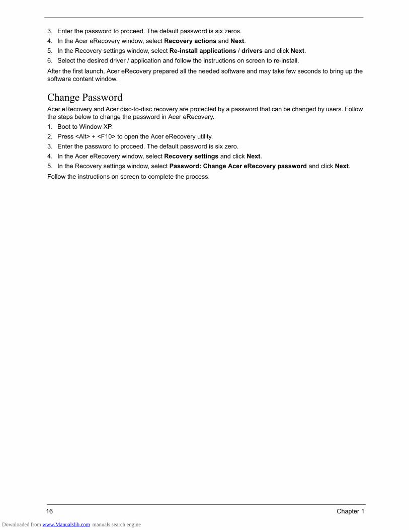
3. Enter the password to proceed. The default password is six zeros.4. In the Acer eRecovery window, select Recovery actions and Next.5. In the Recovery settings window, select Re-install applications / drivers and click Next.6. Select the desired driver / application and follow the instructions on screen to re-install.
After the first launch, Acer eRecovery prepared all the needed software and may take few seconds to bring up the software content window.
Change PasswordAcer eRecovery and Acer disc-to-disc recovery are protected by a password that can be changed by users. Follow the steps below to change the password in Acer eRecovery.1. Boot to Window XP.2. Press <Alt> + <F10> to open the Acer eRecovery utility.3. Enter the password to proceed. The default password is six zero.4. In the Acer eRecovery window, select Recovery settings and click Next.5. In the Recovery settings window, select Password: Change Acer eRecovery password and click Next.Follow the instructions on screen to complete the process.
Downloaded from www.Manualslib.com manuals search engine
Chapter 1 17
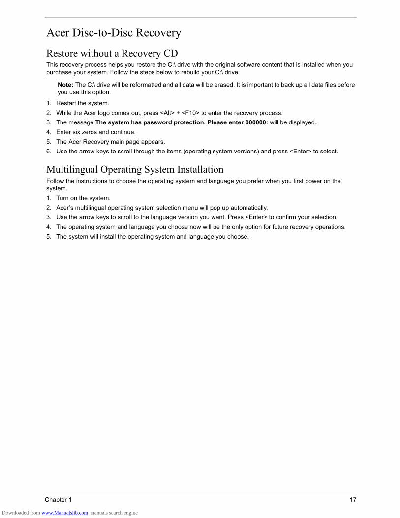
Acer Disc-to-Disc RecoveryRestore without a Recovery CDThis recovery process helps you restore the C:\ drive with the original software content that is installed when you purchase your system. Follow the steps below to rebuild your C:\ drive.
Note: The C:\ drive will be reformatted and all data will be erased. It is important to back up all data files before you use this option.
1. Restart the system.2. While the Acer logo comes out, press <Alt> + <F10> to enter the recovery process.3. The message The system has password protection. Please enter 000000: will be displayed.4. Enter six zeros and continue.5. The Acer Recovery main page appears.6. Use the arrow keys to scroll through the items (operating system versions) and press <Enter> to select.
Multilingual Operating System InstallationFollow the instructions to choose the operating system and language you prefer when you first power on the system.1. Turn on the system.2. Acer’s multilingual operating system selection menu will pop up automatically.3. Use the arrow keys to scroll to the language version you want. Press <Enter> to confirm your selection.4. The operating system and language you choose now will be the only option for future recovery operations.5. The system will install the operating system and language you choose.
Downloaded from www.Manualslib.com manuals search engine
18 Chapter 1
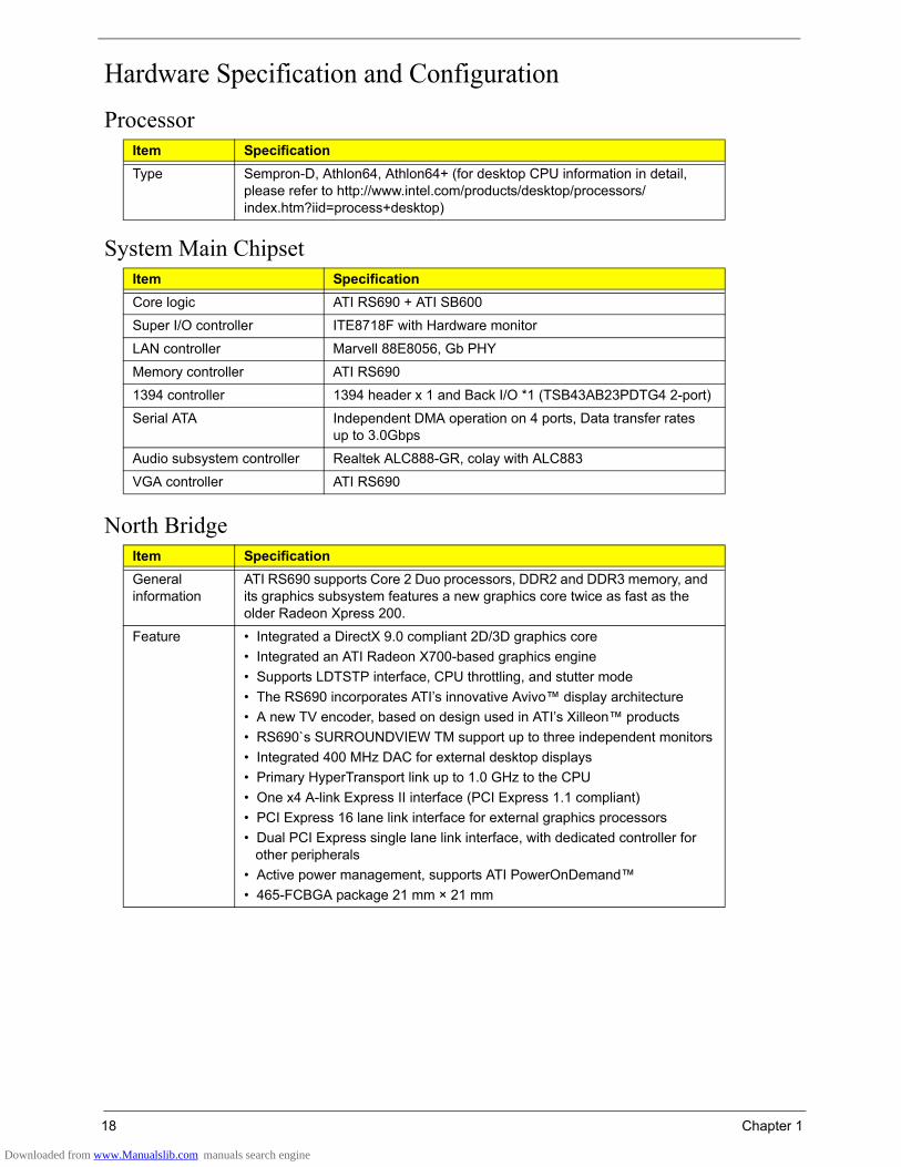
Hardware Specification and ConfigurationProcessor
System Main Chipset
North Bridge
Item SpecificationType Sempron-D, Athlon64, Athlon64+ (for desktop CPU information in detail,
please refer to http://www.intel.com/products/desktop/processors/index.htm?iid=process+desktop)
Item SpecificationCore logic ATI RS690 + ATI SB600
Super I/O controller ITE8718F with Hardware monitor
LAN controller Marvell 88E8056, Gb PHY
Memory controller ATI RS690
1394 controller 1394 header x 1 and Back I/O *1 (TSB43AB23PDTG4 2-port)
Serial ATA Independent DMA operation on 4 ports, Data transfer rates up to 3.0Gbps
Audio subsystem controller Realtek ALC888-GR, colay with ALC883
VGA controller ATI RS690
Item SpecificationGeneral information
ATI RS690 supports Core 2 Duo processors, DDR2 and DDR3 memory, and its graphics subsystem features a new graphics core twice as fast as the older Radeon Xpress 200.
Feature • Integrated a DirectX 9.0 compliant 2D/3D graphics core• Integrated an ATI Radeon X700-based graphics engine• Supports LDTSTP interface, CPU throttling, and stutter mode• The RS690 incorporates ATI’s innovative Avivo™ display architecture• A new TV encoder, based on design used in ATI’s Xilleon™ products• RS690`s SURROUNDVIEW TM support up to three independent monitors• Integrated 400 MHz DAC for external desktop displays• Primary HyperTransport link up to 1.0 GHz to the CPU• One x4 A-link Express II interface (PCI Express 1.1 compliant)• PCI Express 16 lane link interface for external graphics processors• Dual PCI Express single lane link interface, with dedicated controller for
other peripherals• Active power management, supports ATI PowerOnDemand™• 465-FCBGA package 21 mm × 21 mm
Downloaded from www.Manualslib.com manuals search engine
Chapter 1 19
South Bridge
Wake-up Event Specification (Default Setting in BIOS)
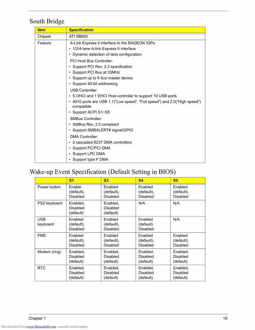
Item SpecificationChipset ATI SB600
Feature A-Link Express II interface to the RADEON IGPs:• 1/2/4-lane A-link Express II interface• Dynamic detection of lane configuration
PCI Host Bus Controller:• Support PCI Rev. 2.3 specification• Support PCI Bus at 33MHz• Support up to 6 bus master device• Support 40-bit addressing
USB Controller:• 5 OHCI and 1 EHCI Host controller to support 10 USB ports• All10 ports are USB 1.1("Low speed", "Full speed") and 2.0("High speed")
compatible• Support ACPI S1~S5
SMBus Controller:• SMBus Rev. 2.0 compliant• Support SMBALERT# signal/GPIO
DMA Controller:• 2 cascaded 8237 DMA controllers• Support PC/PCI DMA• Support LPC DMA• Support type F DMA
S1 S3 S4 S5Power button Enable
(default), Disabled
Enabled (default),Disabled
Enabled (default), Disabled
Enabled (default), Disabled
PS2 keyboard Enabled, Disabled (default)
Enabled, Disabled (default)
N/A N/A
USB keyboard
Enabled (default), Disabled
Enabled (default), Disabled
Enabled (default) Disabled
N/A
PME Enabled (default),Disabled
Enabled (default), Disabled
Enabled (default), Disabled
Enabled (default), Disabled
Modem (ring) Enabled, Disabled (default)
Enabled, Disabled (default)
Enabled, Disabled (default)
Enabled, Disabled (default)
RTC Enabled, Disabled (default)
Enabled, Disabled (default)
Enabled, Disabled (default)
Enabled, Disabled (default)
Downloaded from www.Manualslib.com manuals search engine
20 Chapter 1
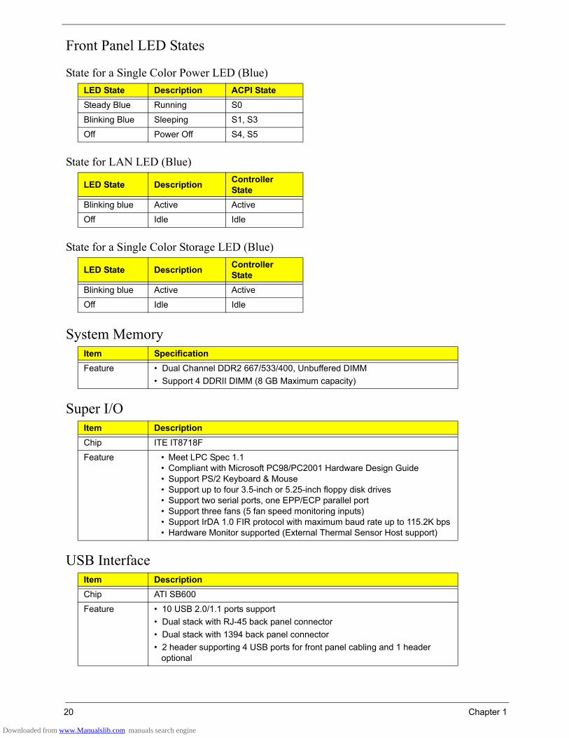
Front Panel LED States
State for a Single Color Power LED (Blue)
State for LAN LED (Blue)
State for a Single Color Storage LED (Blue)
System Memory
Super I/O
USB Interface
LED State Description ACPI StateSteady Blue Running S0
Blinking Blue Sleeping S1, S3
Off Power Off S4, S5
LED State Description Controller State
Blinking blue Active Active
Off Idle Idle
LED State Description Controller State
Blinking blue Active Active
Off Idle Idle
Item SpecificationFeature • Dual Channel DDR2 667/533/400, Unbuffered DIMM
• Support 4 DDRII DIMM (8 GB Maximum capacity)
Item DescriptionChip ITE IT8718F
Feature • Meet LPC Spec 1.1• Compliant with Microsoft PC98/PC2001 Hardware Design Guide• Support PS/2 Keyboard & Mouse• Support up to four 3.5-inch or 5.25-inch floppy disk drives• Support two serial ports, one EPP/ECP parallel port• Support three fans (5 fan speed monitoring inputs)• Support IrDA 1.0 FIR protocol with maximum baud rate up to 115.2K bps• Hardware Monitor supported (External Thermal Sensor Host support)
Item DescriptionChip ATI SB600
Feature • 10 USB 2.0/1.1 ports support• Dual stack with RJ-45 back panel connector• Dual stack with 1394 back panel connector • 2 header supporting 4 USB ports for front panel cabling and 1 header
optional
Downloaded from www.Manualslib.com manuals search engine
Chapter 1 21
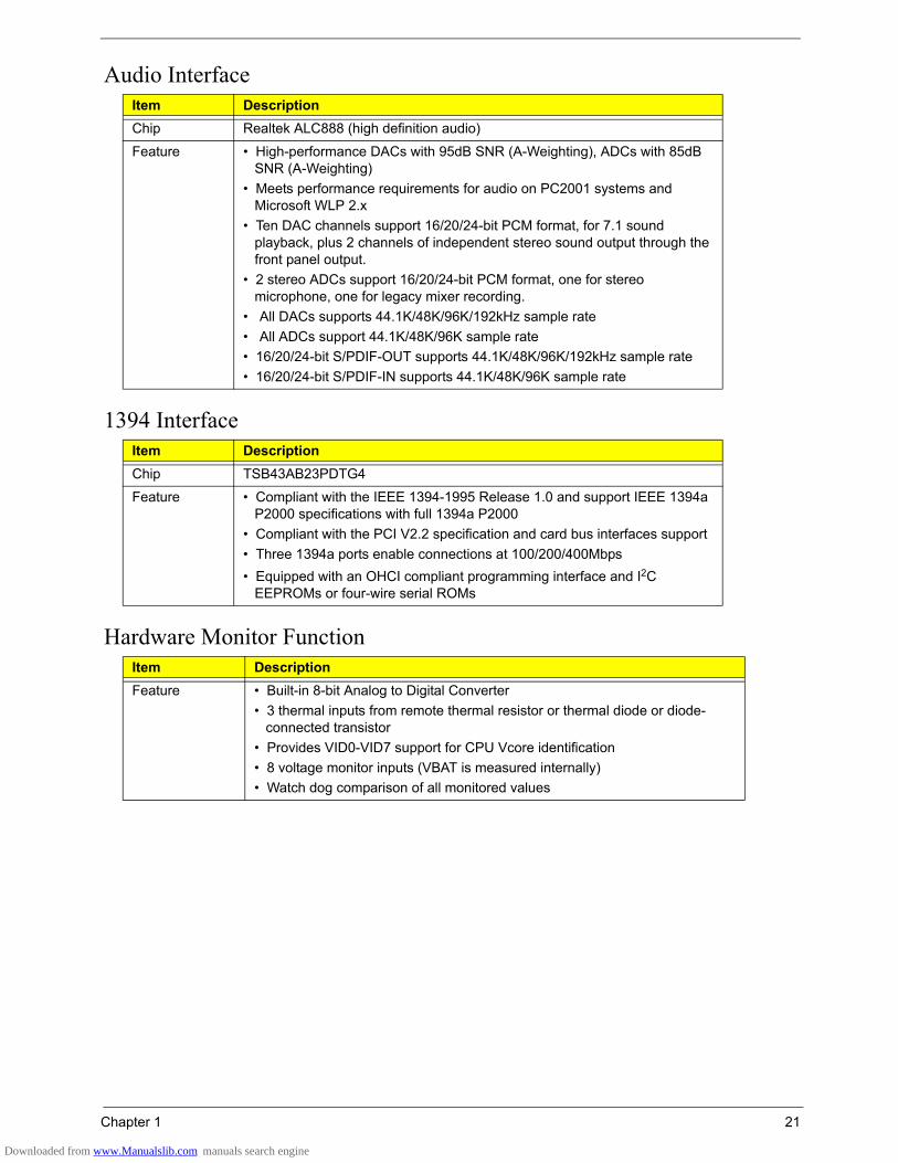
Audio Interface
1394 Interface
Hardware Monitor Function
Item DescriptionChip Realtek ALC888 (high definition audio)
Feature • High-performance DACs with 95dB SNR (A-Weighting), ADCs with 85dB SNR (A-Weighting)
• Meets performance requirements for audio on PC2001 systems and Microsoft WLP 2.x
• Ten DAC channels support 16/20/24-bit PCM format, for 7.1 sound playback, plus 2 channels of independent stereo sound output through the front panel output.
• 2 stereo ADCs support 16/20/24-bit PCM format, one for stereo microphone, one for legacy mixer recording.
• All DACs supports 44.1K/48K/96K/192kHz sample rate• All ADCs support 44.1K/48K/96K sample rate• 16/20/24-bit S/PDIF-OUT supports 44.1K/48K/96K/192kHz sample rate• 16/20/24-bit S/PDIF-IN supports 44.1K/48K/96K sample rate
Item DescriptionChip TSB43AB23PDTG4
Feature • Compliant with the IEEE 1394-1995 Release 1.0 and support IEEE 1394a P2000 specifications with full 1394a P2000
• Compliant with the PCI V2.2 specification and card bus interfaces support• Three 1394a ports enable connections at 100/200/400Mbps• Equipped with an OHCI compliant programming interface and I2C
EEPROMs or four-wire serial ROMs
Item DescriptionFeature • Built-in 8-bit Analog to Digital Converter
• 3 thermal inputs from remote thermal resistor or thermal diode or diode-connected transistor
• Provides VID0-VID7 support for CPU Vcore identification• 8 voltage monitor inputs (VBAT is measured internally)• Watch dog comparison of all monitored values
Downloaded from www.Manualslib.com manuals search engine
22 Chapter 1
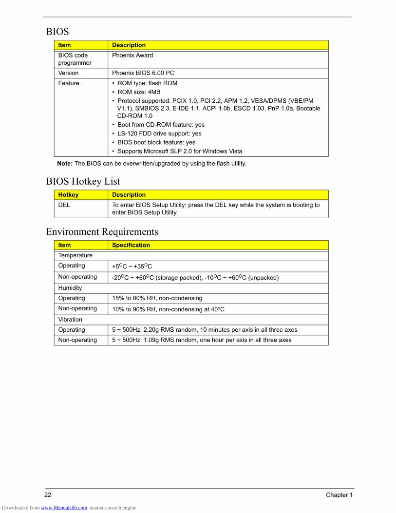
BIOS
Note: The BIOS can be overwritten/upgraded by using the flash utility.
BIOS Hotkey List
Environment Requirements
Item DescriptionBIOS code programmer
Phoenix Award
Version Phoenix BIOS 6.00 PC
Feature • ROM type: flash ROM• ROM size: 4MB• Protocol supported: PCIX 1.0, PCI 2.2, APM 1.2, VESA/DPMS (VBE/PM
V1.1), SMBIOS 2.3, E-IDE 1.1, ACPI 1.0b, ESCD 1.03, PnP 1.0a, Bootable CD-ROM 1.0
• Boot from CD-ROM feature: yes• LS-120 FDD drive support: yes• BIOS boot block feature: yes• Supports Microsoft SLP 2.0 for Windows Vista
Hotkey DescriptionDEL To enter BIOS Setup Utility: press the DEL key while the system is booting to
enter BIOS Setup Utility.
Item SpecificationTemperature
Operating +5OC ~ +35OC
Non-operating -20OC ~ +60OC (storage packed), -10OC ~ +60OC (unpacked)
Humidity
Operating 15% to 80% RH, non-condensing
Non-operating 10% to 90% RH, non-condensing at 40oC
Vibration
Operating 5 ~ 500Hz, 2.20g RMS random, 10 minutes per axis in all three axes
Non-operating 5 ~ 500Hz, 1.09g RMS random, one hour per axis in all three axes
Downloaded from www.Manualslib.com manuals search engine
Chapter 1 23
Power Management Function (ACPI Support Function)Device Standby Mode
• Independent power management timer for hard disk drive devices (zero to 15 minutes, time step = one minute).
• Hard disk drive goes into Standby mode (for ATA standard interface).• Disable V-sync to control the VESA DPMS monitor.• Resume method: device activated (keyboard for DOS, keyboard & mouse for Windows).• Resume recovery time: three to five seconds.
Global Standby Mode• Global power management timer (two to 120 minutes, time step = 10 minutes).• Hard disk drive goes into Standby mode (for ATA standard interface).• Disable H-sync and V-sync signals to control the VESA DPMS monitor.• Resume method: return to original state by pushing external switch button, modem ring in, keyboard and
mouse for APM mode.• Resume recovery time: seven to 10 seconds.
Suspend Mode• Independent power management timer (two to 120 minutes, time step = 10 minutes) or pushing external
switch button.• CPU goes into SMM.• CPU asserts STPCLK# and goes into the Stop Grant state.• LED on the panel turns amber color.• Hard disk drive goes into SLEEP mode (for ATA standard interface).• Disable H-sync and V-sync signals to control the VESA DPMS monitor.• Ultra I/O and VGA chip go into power saving mode.• Resume method: return to original state by pushing external switch button, modem ring in, keyboard and
mouse for APM mode.• Return to original state by pushing external switch button, modem ring in and USB keyboard for ACPI
mode.
ACPI• ACPI specification 1.0b• S0, S1, S3 and S5 sleep state support• Onboard device power management support• Onboard device configuration support
Downloaded from www.Manualslib.com manuals search engine
Chapter 2 25
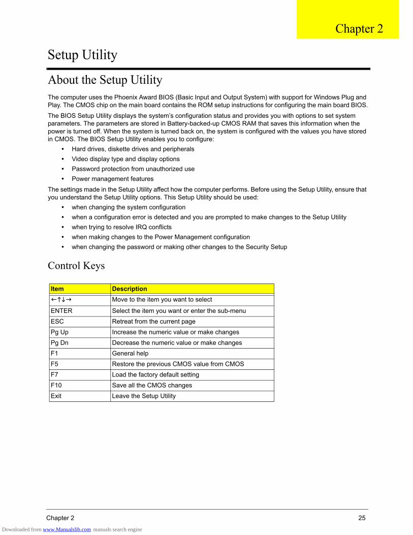
About the Setup UtilityThe computer uses the Phoenix Award BIOS (Basic Input and Output System) with support for Windows Plug and Play. The CMOS chip on the main board contains the ROM setup instructions for configuring the main board BIOS.
The BIOS Setup Utility displays the system’s configuration status and provides you with options to set system parameters. The parameters are stored in Battery-backed-up CMOS RAM that saves this information when the power is turned off. When the system is turned back on, the system is configured with the values you have stored in CMOS. The BIOS Setup Utility enables you to configure:
• Hard drives, diskette drives and peripherals• Video display type and display options• Password protection from unauthorized use• Power management features
The settings made in the Setup Utility affect how the computer performs. Before using the Setup Utility, ensure that you understand the Setup Utility options. This Setup Utility should be used:
• when changing the system configuration• when a configuration error is detected and you are prompted to make changes to the Setup Utility• when trying to resolve IRQ conflicts• when making changes to the Power Management configuration• when changing the password or making other changes to the Security Setup
Control Keys
Item DescriptionMove to the item you want to select
ENTER Select the item you want or enter the sub-menu
ESC Retreat from the current page
Pg Up Increase the numeric value or make changes
Pg Dn Decrease the numeric value or make changes
F1 General help
F5 Restore the previous CMOS value from CMOS
F7 Load the factory default setting
F10 Save all the CMOS changes
Exit Leave the Setup Utility
Chapter 2
Setup Utility
Downloaded from www.Manualslib.com manuals search engine
26 Chapter 2
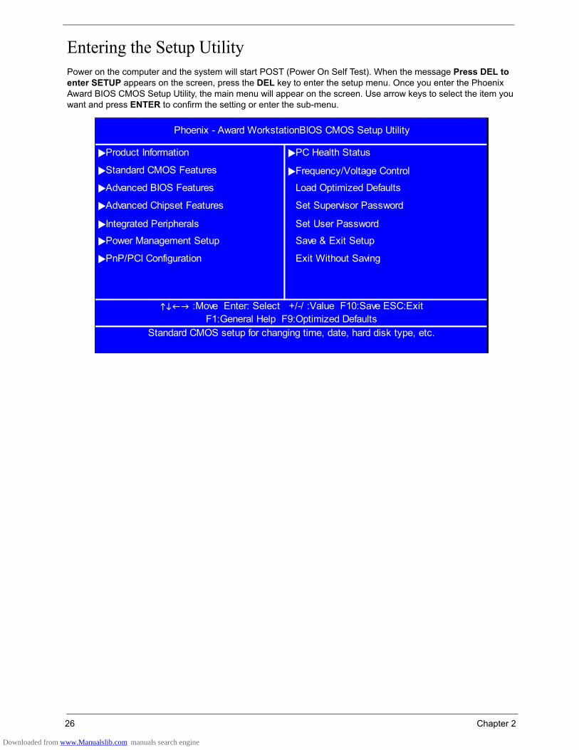
Entering the Setup UtilityPower on the computer and the system will start POST (Power On Self Test). When the message Press DEL to enter SETUP appears on the screen, press the DEL key to enter the setup menu. Once you enter the Phoenix Award BIOS CMOS Setup Utility, the main menu will appear on the screen. Use arrow keys to select the item you want and press ENTER to confirm the setting or enter the sub-menu.
Frequency/Voltage Control
Integrated Peripherals Set User Password
PnP/PCI Configuration
Load Optimized Defaults
Set Supervisor Password
Exit Without Saving
Phoenix - Award WorkstationBIOS CMOS Setup Utility
Product Information PC Health Status
Save & Exit Setup
Advanced BIOS Features
Advanced Chipset Features
Power Management Setup
Standard CMOS Features
F1:General Help F9:Optimized Defaults Standard CMOS setup for changing time, date, hard disk type, etc.
:Move Enter: Select +/-/ :Value F10:Save ESC:Exit
Downloaded from www.Manualslib.com manuals search engine
Chapter 2 27
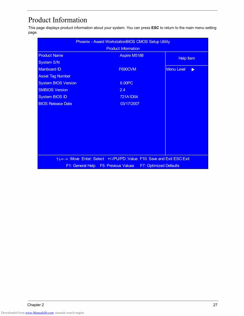
Product InformationThis page displays product information about your system. You can press ESC to return to the main menu setting page.
Phoenix - Award WorkstationBIOS CMOS Setup Utility
Product Information
Product Name Aspire M5188Help Item
System S/N
Mainboard ID F690CVM Menu Level
Asset Tag Number
System BIOS Version 6.00PC
SMBIOS Version 2.4
System BIOS ID 721A1D04
BIOS Release Date 03/17/2007
:Move Enter: Select +/-/PU/PD :Value F10: Save and Exit ESC:Exit
F1: General Help F5: Previous Values F7: Optimized Defaults
Downloaded from www.Manualslib.com manuals search engine
28 Chapter 2
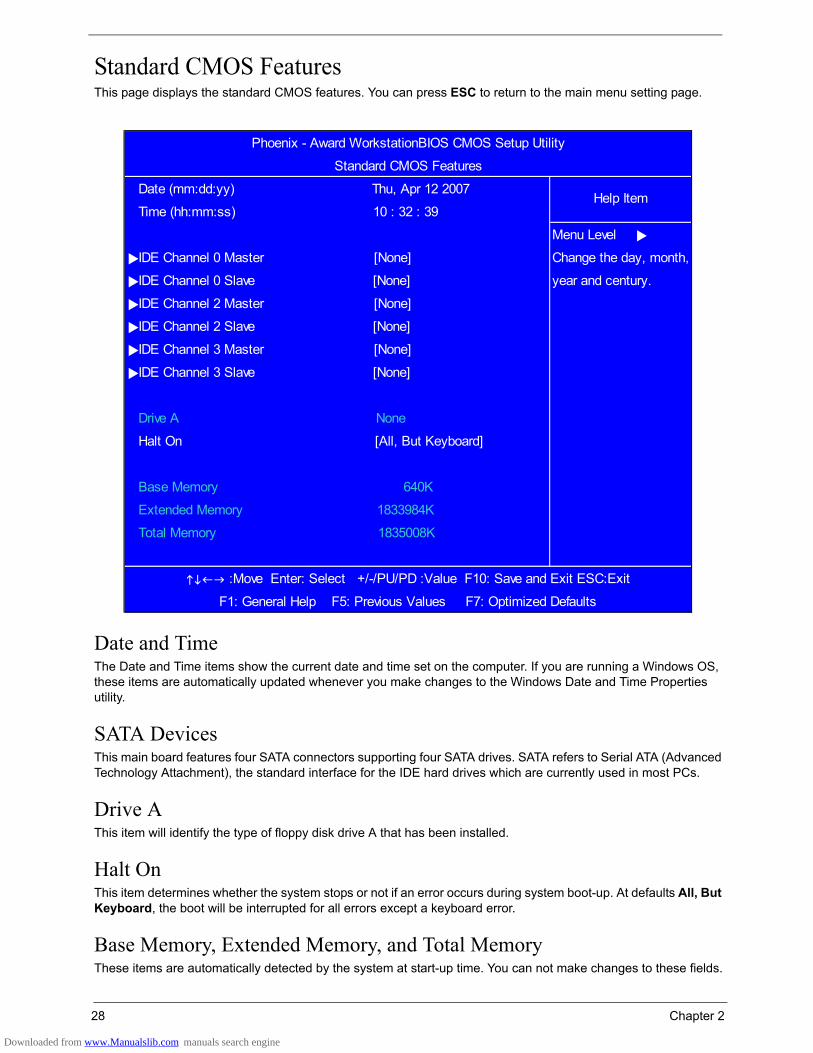
Standard CMOS FeaturesThis page displays the standard CMOS features. You can press ESC to return to the main menu setting page.
Date and TimeThe Date and Time items show the current date and time set on the computer. If you are running a Windows OS, these items are automatically updated whenever you make changes to the Windows Date and Time Properties utility.
SATA DevicesThis main board features four SATA connectors supporting four SATA drives. SATA refers to Serial ATA (Advanced Technology Attachment), the standard interface for the IDE hard drives which are currently used in most PCs.
Drive AThis item will identify the type of floppy disk drive A that has been installed.
Halt OnThis item determines whether the system stops or not if an error occurs during system boot-up. At defaults All, But Keyboard, the boot will be interrupted for all errors except a keyboard error.
Base Memory, Extended Memory, and Total MemoryThese items are automatically detected by the system at start-up time. You can not make changes to these fields.
:Move Enter: Select +/-/PU/PD :Value F10: Save and Exit ESC:Exit
F1: General Help F5: Previous Values F7: Optimized Defaults
Extended Memory 1833984K
Base Memory 640K
Total Memory 1835008K
IDE Channel 3 Slave [None]
Drive A None
Halt On [All, But Keyboard]
IDE Channel 2 Slave [None]
IDE Channel 3 Master [None]
IDE Channel 0 Slave [None] year and century.
IDE Channel 2 Master [None]
Menu Level
IDE Channel 0 Master [None] Change the day, month,
Phoenix - Award WorkstationBIOS CMOS Setup Utility
Standard CMOS Features
Date (mm:dd:yy) Thu, Apr 12 2007Help Item
Time (hh:mm:ss) 10 : 32 : 39
Downloaded from www.Manualslib.com manuals search engine

Chapter 2 29
Advanced BIOS FeaturesThis page displays advanced BIOS features. You can press ESC to return to the main menu setting page.
Virus WarningThis item enables or disables the boot sector virus protection.
CPU Internal Cache/External CacheCache memory is additional memory that is much faster than conventional DRAM (system memory). CPUs from 486-type on up contain internal cache memory, and most, but not all, modern PCs have additional (external) cache memory. When the CPU requests data, the system transfers the requested data from the main DRAM into cache
:Move Enter: Select +/-/PU/PD :Value F10: Save and Exit ESC:Exit
F1: General Help F5: Previous Values F7: Optimized Defaults
X Typematic Delay (Msec) 250
Security Option [Setup]
APIC Mode Enabled
MPS Version Control For OS [1.4]
OS Select For DRAM > 64MB [Non-OS2]
HDD S.M.A.R.T. Capability [Disabled]
Bootblock Write Protect [Enabled]
Silent Boot [Enabled]
Typematic Rate Setting [Disabled]
X Typematic Rate (chars/sec) 6
Small Logo (EPA) Show [Disabled]
Configuration Table [Disabled]
Boot Other Device [Enabled]
Boot Up Floppy Seek [Disabled]
Boot Up Num Lock Status [On]
Gate A20 Option [Fast]
Second Boot Device [CDROM]
Third Boot Device [Disabled]
Quick Power On Self Test [Enabled]
First Boot Device [Hard Disk]
CPU Internal Cache [Enabled] Menu Level
External Cache [Enabled]
Phoenix - Award WorkstationBIOS CMOS Setup Utility
Advanced BIOS Features
Hard Disk Boot Priority [Press Enter]Help Item
Virus Warning [Disabled]
Downloaded from www.Manualslib.com manuals search engine
30 Chapter 2
memory, for even faster access by the CPU. Disabling the Internal/External Caching may affect processing speeds.
Quick Power On Self TestUse this item to shorten the POST and have the system startup faster. You might like to enable this item after you are confident that your system hardware is operating smoothly.
First / Second / Third Boot DeviceUse this three items to select the priority and order of the devices that your system searches for an operating system when the system is powering on.
Boot Other DeviceWhen enabled, the system searches all other possible locations for an operating system if it fails to find one in the devices specified under the First, Second, and Third boot devices.
Boot Up Floppy SeekThis item controls whether the BIOS checks for a floppy drive while booting up.
Boot Up NumLock StatusThis item defines if the keyboard NumLock key is active when your system is booted.
Gate A20 OptionThis item defines how the system handles legacy software that was written for an earlier generation of processors. Set this item for the default value.
Typematic Rate Setting If this item is enabled, you can use the following two items to set the Typematic Rate and the Typematic Delay settings for the keyboard. The default setting is <Disabled> which uses the defaults below:
• Typematic Rate (Chars/Sec): Use this item to define how many characters per second are generated by a held-down key. The default setting is 6.
• Typematic Delay (Msec): Use this item to define how many milliseconds must elapse before a held-down key begins generating repeat characters. The default setting is 250.
Security OptionIf you have installed password protection, this item defines if the password is required at system start up, or if it is only required when a user tries to enter the Setup Utility.
APIC ModeThis item allows you to enable or disable the APIC (Advanced Programmable Interrupt Controller) mode. APIC provides symmetric multi-processing (SMP) for systems.
MPS Version Control For OSThis item specifies which version of MPS (Multi-Processor Specification) this main board will use. Set this item for its default setting.
OS Select for DRAM > 64 MBThis item is only required if you have installed more than 64 MB of memory and you are running the OS/2 operating system. Otherwise, leave this item at the default.
Downloaded from www.Manualslib.com manuals search engine
Chapter 2 31
HDD S.M.A.R.T CapabilityThe S.M.A.R.T (Self-Monitoring, Analysis, and Reporting Technology) system is a diagnostics technology that monitors and predicts device performance. S.M.A.R.T software resides on both the disk drive and the host computer.
Silent BootThis item enables or disables the Silent Boot function.
Small Logo (EPA) Show Determines whether the EPA logo appears during boot up.
Configuration TableThis item enables or disables the Configuration Table in BIOS setting.
Bootblock Write ProtectWhen enabled, Boot block write protection allows the boot block area to be protected by a write-protect pin.
Downloaded from www.Manualslib.com manuals search engine

32 Chapter 2
Hard Disk Boot PriorityScroll to this item and press ENTER to enter the sub-menu below.
down the list. Press
<Esc> to exit this
menu.
Phoenix - Award WorkstationBIOS CMOS Setup Utility
Hard Disk Boot Priority
1. Ch2 M. : ST3808110ASHelp Item
2. Bootable Add-in Cards
Menu Level
Use < > or < > to
select a device, then
press <+> to move it
up, or <-> to move it
:Move Enter: Select +/-/PU/PD :Value F10: Save and Exit ESC:Exit
F1: General Help F5: Previous Values F7: Optimized Defaults
Downloaded from www.Manualslib.com manuals search engine
Chapter 2 33
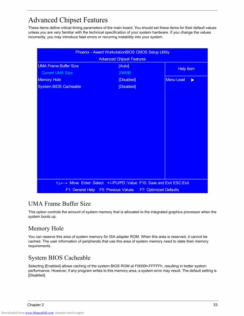
Advanced Chipset FeaturesThese items define critical timing parameters of the main board. You should set these items for their default values unless you are very familiar with the technical specification of your system hardware. If you change the values incorrectly, you may introduce fatal errors or recurring instability into your system.
UMA Frame Buffer SizeThis option controls the amount of system memory that is allocated to the integrated graphics processor when the system boots up.
Memory HoleYou can reserve this area of system memory for ISA adapter ROM. When this area is reserved, it cannot be cached. The user information of peripherals that use this area of system memory need to state their memory requirements.
System BIOS CacheableSelecting [Enabled] allows caching of the system BIOS ROM at F0000h-FFFFFh, resulting in better system performance. However, if any program writes to this memory area, a system error may result. The default setting is [Disabled].
Phoenix - Award WorkstationBIOS CMOS Setup Utility
Advanced Chipset Features
UMA Frame Buffer Size [Auto]Help Item
Current UMA Size 256MB
Memory Hole [Disabled] Menu Level
System BIOS Cacheable [Disabled]
:Move Enter: Select +/-/PU/PD :Value F10: Save and Exit ESC:Exit
F1: General Help F5: Previous Values F7: Optimized Defaults
Downloaded from www.Manualslib.com manuals search engine
34 Chapter 2
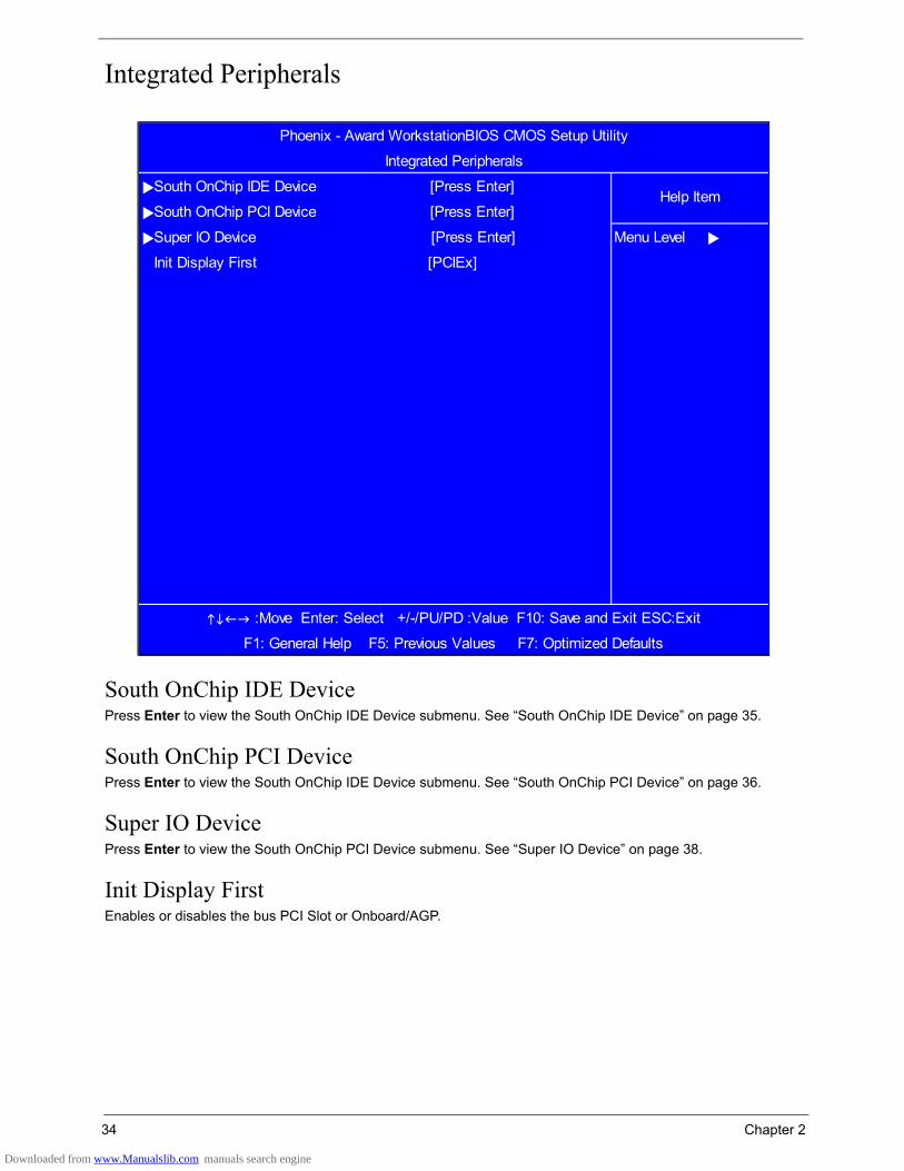
Integrated Peripherals
South OnChip IDE DevicePress Enter to view the South OnChip IDE Device submenu. See “South OnChip IDE Device” on page 35.
South OnChip PCI DevicePress Enter to view the South OnChip IDE Device submenu. See “South OnChip PCI Device” on page 36.
Super IO DevicePress Enter to view the South OnChip PCI Device submenu. See “Super IO Device” on page 38.
Init Display FirstEnables or disables the bus PCI Slot or Onboard/AGP.
Phoenix - Award WorkstationBIOS CMOS Setup Utility
Integrated Peripherals
South OnChip IDE Device [Press Enter]Help Item
South OnChip PCI Device [Press Enter]
Super IO Device [Press Enter] Menu Level
Init Display First [PCIEx]
:Move Enter: Select +/-/PU/PD :Value F10: Save and Exit ESC:Exit
F1: General Help F5: Previous Values F7: Optimized Defaults
Downloaded from www.Manualslib.com manuals search engine

Chapter 2 35
South OnChip IDE DeviceScroll to this item and press Enter to enter the sub-menu shown as below.
IDE DMA Transfer AccessThis item allows you to enable the transfer access of the IDE DMA.
OnChip IDE ChannelSelect Enabled to activate IDE channel.
IDE Primary/Secondary Master/Slave PIOEach IDE channel supports a master device and a slave device. These four items let you assign which kind of PIO (Programmed Input/Output) is used by IDE devices. Choose Auto to let the system auto detect which PIO mode is optimal, or select a PIO mode from zero to four.
IDE Primary/Secondary Master/Slave UltraDMAThis main board supports UltraDMA technology, which provides faster access to IDE devices. If you install a device that supports UltraDMA, you can change the item on this list to Auto. You may have to install the UltraDMA driver supplied with this main board in order to use an UltraDMA device.
IDE HDD Block ModeEnable this field if the IDE hard drive supports block mode. Block mode enables BIOS to automatically detect the optimal number of block read and writes per sector that the drive can support and improves the speed of access to IDE devices.
Phoenix - Award WorkstationBIOS CMOS Setup Utility
South OnChip IDE Device
IDE DMA transfer access [Enabled]Help Item
OnChip IDE Channel 0 [Enabled]
Primary Master PIO [Auto] Menu Level
Primary Slave PIO [Auto]
Primary Master UDMA [Auto]
Primary Slave UDMA [Auto]
IDE HDD Block Mode [Enabled]
:Move Enter: Select +/-/PU/PD :Value F10: Save and Exit ESC:Exit
F1: General Help F5: Previous Values F7: Optimized Defaults
Downloaded from www.Manualslib.com manuals search engine

36 Chapter 2
South OnChip PCI DeviceScroll to this item and press Enter to enter the sub-menu shown as below.
ATI Azalia AudioATI Azalia Audio provides superior Audio Onboard, negating the need for 3rd party audio cards. The default setting is [Enabled].
ATI SATA ControllerThis item appears in the BIOS of motherboards with a secondary Serial ATA controller (separate from the motherboard chipset). When enabled, the secondary Serial ATA controller will function normally. Serial ATA devices connected to it will be accessible to the system. When disabled, the secondary Serial ATA controller will be disabled. Serial ATA devices connected to it will not be accessible to the system.
ATI SATA TypeThis item sets the SATA Cable Type in use. The default is [Native IDE].
USB EHCI ControllerEnables or disables the Universal Serial Bus (USB) controller and Enhanced Host Controller Interface.
ATI SATA Controller [Enabled]
Phoenix - Award WorkstationBIOS CMOS Setup Utility
South OnChip PCI Device
ATI Azalia Audio [Enabled]Help Item
ATI SATA Type [Native IDE] Menu Level
USB EHCI Controller [Enabled]
OnChip USB Controller [Enabled]
OnChip USB KBC Controller [Enabled]
USB Mouse Support [Enabled]
Onboard LAN Controller [Enabled]
Onboard Lan Boot ROM [Enabled]
Onboard 1394 Controller [Enabled]
:Move Enter: Select +/-/PU/PD :Value F10: Save and Exit ESC:Exit
Downloaded from www.Manualslib.com manuals search engine
Chapter 2 37
OnChip USB ControllerEnables or disables the Universal Serial Bus (USB) controller and any USB peripherals present.
OnChip USB KBC ControllerEnables or disables the Universal Serial Bus (USB) controller and USB keyboard if present.
USB Mouse SupportYou can enable this item if you want to use a mouse connected through the USB port in a legacy operating system (such as DOS) that does not support Plug and Play.
Onboard LAN ControllerThis item allows users to enable or disable the onboard LAN Controller function.
Onboard Lan Boot ROMUse this item to enable or disable the booting from the onboard LAN or a network add-on card with a remote boot
ROM installed.
Onboard 1394 ControllerUse this item to enable or disable the onboard VIA 1394 device.
Downloaded from www.Manualslib.com manuals search engine

38 Chapter 2
Super IO Device
Onboard FDC ControllerIf your system has a floppy disk controller (FDC) installed on the system board and you want to use it, you can select Enabled. If you install an add-in FDC or the system has no floppy drive, select Disabled in this field.
Onboard Serial Port 1This item allows users to manually set the address for serial port 1.
Onboard Serial Port 2Use this item to enable or disable the onboard parallel port and to assign a port address.
UART Mode SelectSelect an operating mode for the serial port. The default is [Normal].
UR2 Duplex ModeThis option is only available if an infrared port mode is selected in the UART Mode Select item. Select full or half duplex mode. Full-duplex mode permits simultaneous two-direction transmission. Half-duplex mode permits transmission in one direction only at a time.
:Move Enter: Select +/-/PU/PD :Value F10: Save and Exit ESC:Exit
F1: General Help F5: Previous Values F7: Optimized Defaults
Parallel Port Mode SPP
X ECP Mode Use DMA 3
X UR2 Duplex Mode Half
Onboard Parallel Port [378/IRQ7]
Onbaord Serial Port 2 [2F8/IRQ3] Menu Level
UART Mode Select [Normal]
Phoenix - Award WorkstationBIOS CMOS Setup Utility
Super IO Device
Onboard FDC Controller [Enabled]Help Item
Onbaord Serial Port 1 [3F8/IRQ4]
Downloaded from www.Manualslib.com manuals search engine

Chapter 2 39
Onboard Parallel PortSelect a logical LPT port address and corresponding interrupt for the onboard parallel port.
Parallel Port ModeUse this item to set the parallel port mode. You can select SPP (Standard Parallel Port), ECP (Extended
Capabilities Port), EPP (Enhanced Parallel Port), or EPP & ECP.
ECP Mode Use DMAWhen the onboard parallel port is set for ECP mode, the parallel port can use (DMA) 3 or (DMA) 1.
Downloaded from www.Manualslib.com manuals search engine
40 Chapter 2
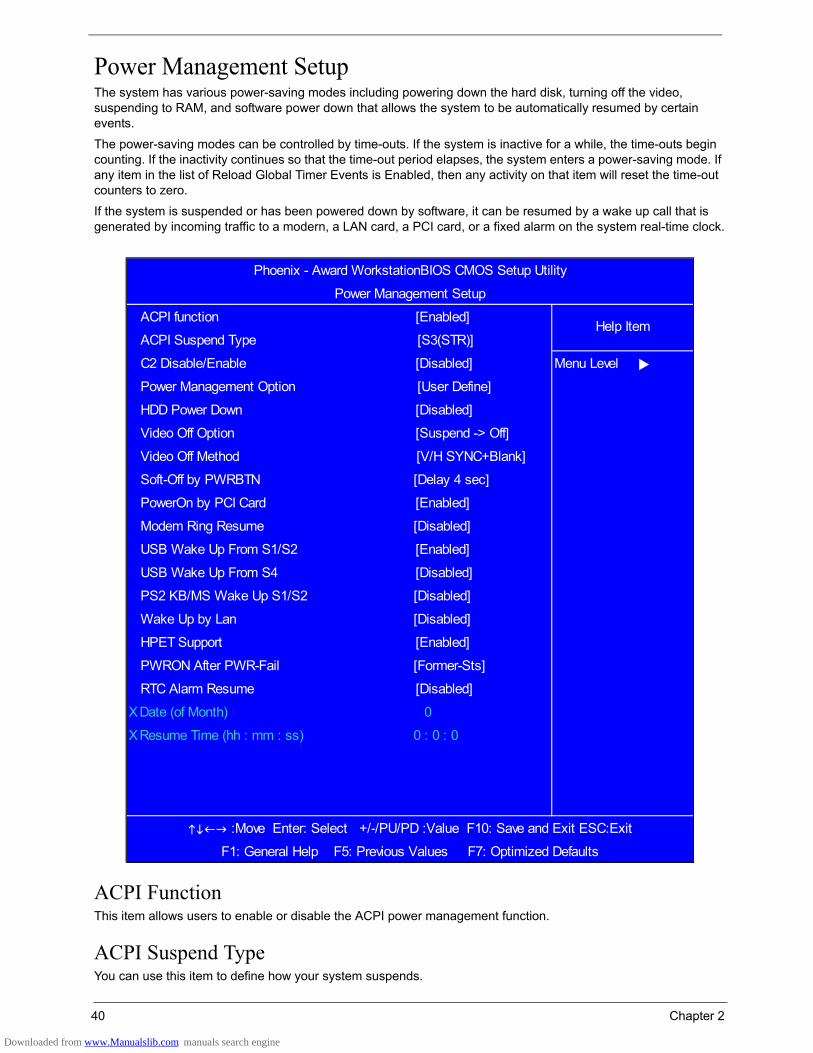
Power Management SetupThe system has various power-saving modes including powering down the hard disk, turning off the video, suspending to RAM, and software power down that allows the system to be automatically resumed by certain events.
The power-saving modes can be controlled by time-outs. If the system is inactive for a while, the time-outs begin counting. If the inactivity continues so that the time-out period elapses, the system enters a power-saving mode. If any item in the list of Reload Global Timer Events is Enabled, then any activity on that item will reset the time-out counters to zero.
If the system is suspended or has been powered down by software, it can be resumed by a wake up call that is generated by incoming traffic to a modern, a LAN card, a PCI card, or a fixed alarm on the system real-time clock.
ACPI FunctionThis item allows users to enable or disable the ACPI power management function.
ACPI Suspend TypeYou can use this item to define how your system suspends.
Phoenix - Award WorkstationBIOS CMOS Setup Utility
Power Management Setup
ACPI function [Enabled]Help Item
ACPI Suspend Type [S3(STR)]
C2 Disable/Enable [Disabled] Menu Level
Video Off Option [Suspend -> Off]
Power Management Option [User Define]
HDD Power Down [Disabled]
Video Off Method [V/H SYNC+Blank]
Soft-Off by PWRBTN [Delay 4 sec]
HPET Support [Enabled]
PowerOn by PCI Card [Enabled]
Wake Up by Lan [Disabled]
Modem Ring Resume [Disabled]
USB Wake Up From S1/S2 [Enabled]
USB Wake Up From S4 [Disabled]
PS2 KB/MS Wake Up S1/S2 [Disabled]
PWRON After PWR-Fail [Former-Sts]
RTC Alarm Resume [Disabled]
X Date (of Month) 0
X Resume Time (hh : mm : ss) 0 : 0 : 0
:Move Enter: Select +/-/PU/PD :Value F10: Save and Exit ESC:Exit
F1: General Help F5: Previous Values F7: Optimized Defaults
Downloaded from www.Manualslib.com manuals search engine
Chapter 2 41
CS2 Disable/EnableEnable or disable the ACPI C2 mode. Default is Disabled.
Power Management OptionThis item acts like a master switch for the power-saving modes and hard disk timeouts. If this item is set to Max Saving, power-saving modes occur after a short timeout. If this item is set to Min Saving, power-saving modes occur after a longer timeout. If the item is set to User Define, manually define timeouts for the power-saving modes.
HDD Power DownSelect the required period of inactivity after which the hard disk drive powers down while all other devices remain active.
Video Off OptionThis option defines if the video is powered down when the system is put into suspend mode.
Video Off MethodThis item defines how the video is powered down to save power.
Soft-Off by PWRBTNUnder ACPI (Advanced Configuration and Power Management Interface) you can create a software power down. In a software power down, the system can be resumed by Wake Up Alarms. This item lets you install a software power down that is controlled by the power button on your system. If the item is set for Instant-Off, then the power button causes a software power down. If the item is set for Delay four Sec., then you have to hold the power button down for four seconds to cause a software power down.
Power On By PCI CardEnables PCI activity to wake up the system from a power-saving mode.
Modem Ring ResumeEnables Modem activity to wake up the system from a power-saving mode.
USB Wakeup From S1/S2Enables USB activity to wake up the system from S1 or S2.
USB Wakeup From S4Enables USB activity to wake up the system from S4.
PS2 KB/MS Wakeup From S1/S2Enables PS/2 keyboard or mouse activity to wake up the system from S1 or S2.
Wakeup By LANEnables LAN activity to wake up the system from a power-saving mode.
HPET SupportEnable or disable support for the High Precision Event Timer (HPET).
PWRON After PWR-FailSets the state to which the computer returns after power failure.
Downloaded from www.Manualslib.com manuals search engine

42 Chapter 2
RTC Alarm ResumeWhen set to Enabled, the Date and Resume Time fields become available. Set the date (day of the month), hour, minute and second to turn on the system. When set to 0 (zero) for the day of the month, the alarm will power on your system every day at the specified time.
Downloaded from www.Manualslib.com manuals search engine
Chapter 2 43
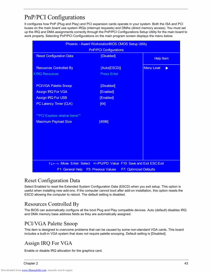
PnP/PCI ConfigurationsIt configures how PnP (Plug and Play) and PCI expansion cards operate in your system. Both the ISA and PCI buses on the main board use system IRQs (interrupt requests) and DMAs (direct memory access). You must set up the IRQ and DMA assignments correctly through the PnP/PCI Configurations Setup Utility for the main board to work properly. Selecting PnP/PCI Configurations on the main program screen displays the menu below.
Reset Configuration DataSelect Enabled to reset the Extended System Configuration Data (ESCD) when you exit setup. This option is useful when installing new add-ons. If the computer cannot boot after add-on installation, this option resets the ESCD allowing the computer to reboot. The default setting is disabled.
Resources Controlled ByThe BIOS can automatically configure all the boot Plug and Play compatible devices. Auto (default) disables IRQ and DMA memory base address fields as they are automatically assigned.
PCI/VGA Palette SnoopThis item is designed to overcome problems that can be caused by some non-standard VGA cards. This board includes a built-in VGA system that does not require palette snooping. Default setting is [Disabled].
Assign IRQ For VGAEnable or disable IRQ allocation for the graphics card.
Assign IRQ For VGA [Enabled]
Assign IRQ For USB [Enabled]
PC Latency Timer (CLK) [64]
**PCI Express relative items**
Maximum Payload Size [4096]
:Move Enter: Select +/-/PU/PD :Value F10: Save and Exit ESC:Exit
F1: General Help F5: Previous Values F7: Optimized Defaults
Resources Controlled By [Auto(ESCD)] Menu Level
PCI/VGA Palette Snoop [Disabled]
X IRQ Resources Press Enter
Phoenix - Award WorkstationBIOS CMOS Setup Utility
PnP/PCI Configurations
Reset Configuration Data [Disabled]Help Item
Downloaded from www.Manualslib.com manuals search engine

44 Chapter 2
Assign IRQ for USBEnable or disable IRQ allocation for the USB (Universal Serial Bus).
PCI Latency Timer (CLK)This item controls how long a PCI device can hold the PCI bus before another device takes over. Setting the latency to longer periods enables a PCI device to retain control of the bus longer before handing it over to another device.
Maximum Payload SizeThis BIOS feature determines the maximum TLP (Transaction Layer Packet) payload size that can be supported by the motherboard chipset's PCI Express controller. The TLP payload size determines the amount of data transmitted within each data packet. When set to 4096, the motherboard chipset's PCI Express controller supports the maximum data payload of 4096 bytes within each TLP. This is the maximum payload size currently supported by the PCI Express protocol.
Downloaded from www.Manualslib.com manuals search engine

Chapter 2 45
PC Health StatusOn the main board that supports hardware monitoring, you can monitor the parameters of critical voltage, temperature and fan speed.
CPU Shut Down TemperatureEnables you to set the maximum temperature that the system can reach before powering down.
Delta Temp. (°C) [ 2]
PWM Start SYS Temp. (°C) [ 42]
Slope PWM Value 2 [ 2]
Delta Temp. (°C) 2 [ 2]
Slope PWM Value [ 2]
Start PWM Value (0~127) [ 64]
Slope PWM Value [ 3]
Delta Temp. (°C) [ 2]
PWM Start SYS Temp. (°C) [ 45]
System Smart FAN Control [Enabled]
PWM Start CPU Temp (°C) [ 45]
Start PWM Value (0~127) [ 48]
Phoenix - Award WorkstationBIOS CMOS Setup Utility
PC Health Status
CPU Shutdown Temperature [90°C/174°C]Help Item
CPU Vcore [1.34V]
+3.3V [3.32V] Menu Level
+5V [5.08V]
+12V [11.96V]
+5VSB [4.94V]
CPU FAN speed 1844 RPM
System FAN speed 1790 RPM
CPU Temperature 64°C
Ambient Temperature 31°C
CPU Temp. Offset [255]
CPU Smart FAN Control [Enabled]
PWM Start CPU Temp (°C) [ 35]
CPU Warning Temperature [Disabled]
Slope PWM Value 2 [ 3]
Delta Temp. (°C) 2 [ 2]
:Move Enter: Select +/-/PU/PD :Value F10: Save and Exit ESC:Exit
F1: General Help F5: Previous Values F7: Optimized Defaults
Downloaded from www.Manualslib.com manuals search engine

46 Chapter 2
Component StatusThe following items display the current status of various components.
• CPU VCore• +3.3V• +5V• +12V• +5VSB• CPU Temperature• Ambient Temperature• CPU FAN speed• System FAN speed
Scroll to these items and enter values as required to customize the Thermal Profile:• CPU Temp. Offset• CPU Warning Temperature• CPU Smart FAN Control• PWM Start CPU Temp• Start PWM Value• Slope PWM Value• Delta Temp.• PWM Start SYS Temp.• Slope PWM Value 2• Delta Temp. (°C) 2• System Smart FAN Control• PWM Start CPU Temp (°C)• Start PWM Value (0~127)• Slope PWM Value• Delta Temp. (°C)• PWM Start SYS Temp. (°C)• Slope PWM Value 2• Delta Temp. (°C) 2
Downloaded from www.Manualslib.com manuals search engine
Chapter 2 47
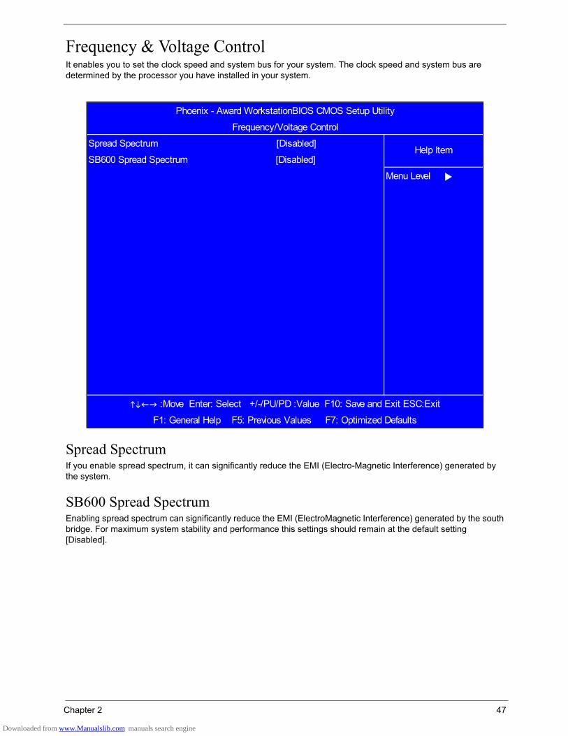
Frequency & Voltage ControlIt enables you to set the clock speed and system bus for your system. The clock speed and system bus are determined by the processor you have installed in your system.
Spread SpectrumIf you enable spread spectrum, it can significantly reduce the EMI (Electro-Magnetic Interference) generated by the system.
SB600 Spread SpectrumEnabling spread spectrum can significantly reduce the EMI (ElectroMagnetic Interference) generated by the south bridge. For maximum system stability and performance this settings should remain at the default setting [Disabled].
:Move Enter: Select +/-/PU/PD :Value F10: Save and Exit ESC:Exit
F1: General Help F5: Previous Values F7: Optimized Defaults
Menu Level
Phoenix - Award WorkstationBIOS CMOS Setup Utility
Frequency/Voltage Control
Spread Spectrum [Disabled]Help Item
SB600 Spread Spectrum [Disabled]
Downloaded from www.Manualslib.com manuals search engine
48 Chapter 2
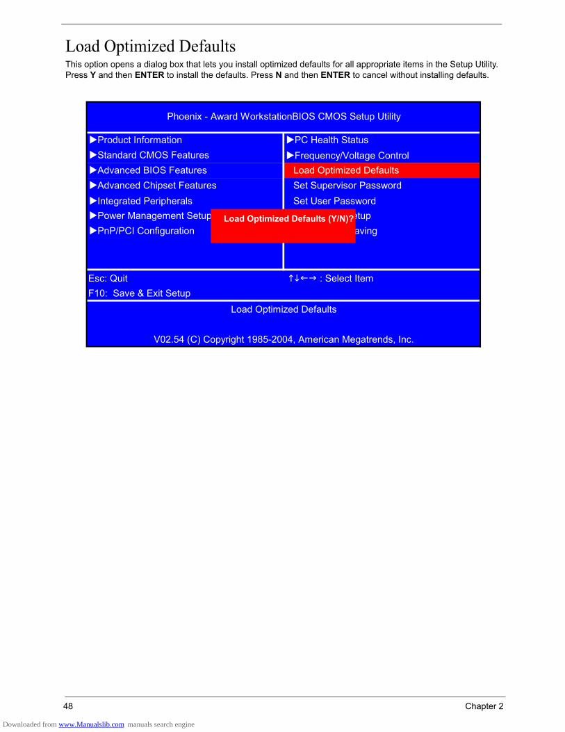
Load Optimized DefaultsThis option opens a dialog box that lets you install optimized defaults for all appropriate items in the Setup Utility. Press Y and then ENTER to install the defaults. Press N and then ENTER to cancel without installing defaults.
Frequency/Voltage Control
Integrated Peripherals Set User Password
Phoenix - Award WorkstationBIOS CMOS Setup Utility
Product Information PC Health StatusStandard CMOS FeaturesAdvanced BIOS Features Load Optimized DefaultsAdvanced Chipset Features Set Supervisor Password
Power Management Setup Save & Exit SetupPnP/PCI Configuration Exit Without Saving
F10: Save & Exit SetupLoad Optimized Defaults
V02.54 (C) Copyright 1985-2004, American Megatrends, Inc.
Esc: Quit : Select Item
Load Optimized Defaults (Y/N)?
Downloaded from www.Manualslib.com manuals search engine

Chapter 2 49
Set Supervisor PasswordWhen this function is selected, the following message appears at the center of the screen to assist you in creating a password.
Enter PasswordType the password, up to eight characters, and press ENTER. The password entered here overwrites any previously entered password from CMOS memory. You will be asked to confirm the password. Type the password again and press ENTER. You can press ESC to abort the selection.
To disable password, just press ENTER when you are prompted to enter password. A message will confirm the password being disabled. Once the password is disabled, the system will boot and you can enter BIOS Setup freely.
Supervisor Password has higher priority than User Password. You can use Supervisor Password when booting the system or entering BIOS Setup to modify all settings. Also you can use User Password when booting the system or entering BIOS Setup but can not modify any setting if Supervisor Password is enabled.
Frequency/Voltage Control
Integrated Peripherals Set User Password
Phoenix - Award WorkstationBIOS CMOS Setup Utility
Product Information PC Health StatusStandard CMOS FeaturesAdvanced BIOS Features Load Optimized DefaultsAdvanced Chipset Features Set Supervisor Password
Power Management Setup Save & Exit SetupPnP/PCI Configuration Exit Without Saving
F10: Save & Exit SetupChange/Set/Disable Password
V02.54 (C) Copyright 1985-2004, American Megatrends, Inc.
Esc: Quit : Select Item
Enter Password:
Downloaded from www.Manualslib.com manuals search engine
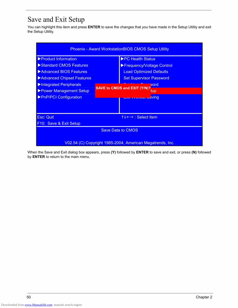
50 Chapter 2
Save and Exit SetupYou can highlight this item and press ENTER to save the changes that you have made in the Setup Utility and exit the Setup Utility.
When the Save and Exit dialog box appears, press (Y) followed by ENTER to save and exit, or press (N) followed by ENTER to return to the main menu.
Frequency/Voltage Control
Integrated Peripherals Set User Password
Phoenix - Award WorkstationBIOS CMOS Setup Utility
Product Information PC Health StatusStandard CMOS FeaturesAdvanced BIOS Features Load Optimized DefaultsAdvanced Chipset Features Set Supervisor Password
Power Management Setup Save & Exit SetupPnP/PCI Configuration Exit Without Saving
F10: Save & Exit SetupSave Data to CMOS
V02.54 (C) Copyright 1985-2004, American Megatrends, Inc.
Esc: Quit : Select Item
SAVE to CMOS and EXIT (Y/N)?
Downloaded from www.Manualslib.com manuals search engine

Chapter 2 51
Exit without SavingYou can highlight this item and press ENTER to discard any changes that you have made in the Setup Utility and exit the Setup Utility.
When the Exit without Saving dialog box appears, press (Y) followed by ENTER to discard changes and exit, or press (N) followed by ENTER to return to the main menu.
Note: If you have made changes to settings that you do not want to save, choose the Discard Changes and Exit and press (Y) followed by ENTER to discard any changes you have made.
Frequency/Voltage Control
Integrated Peripherals Set User Password
Phoenix - Award WorkstationBIOS CMOS Setup Utility
Product Information PC Health StatusStandard CMOS FeaturesAdvanced BIOS Features Load Optimized DefaultsAdvanced Chipset Features Set Supervisor Password
Power Management Setup Save & Exit SetupPnP/PCI Configuration Exit Without Saving
F10: Save & Exit SetupAbandon All Data
V02.54 (C) Copyright 1985-2004, American Megatrends, Inc.
Esc: Quit : Select Item
Quit Without Saving (Y/N)?
Downloaded from www.Manualslib.com manuals search engine

Chapter 3 53
General InformationThis chapter contains step-by-step procedures on how to disassemble and reassemble the Angora AM5610/AM3610 for maintenance and troubleshooting. In the coming pages, the first part of the disassembly instruction is for Angora AM5610 and the second part is for Angora AM3610.
To disassemble the notebook, you need the tools below:• Wrist ground strap and conductive mat for preventing electrostatic discharge• Small Philips screw driver• Flat head screw driver• Hexagonal driver• Tweezers
Note: The screws for the different components vary in size. During the disassembly process, group the screws with the corresponding components to avoid mismatch when putting back the components. When you remove the stripe cover, please be careful not to scrape the cover.
Before You BeginBefore proceeding with the disassembly procedure, you have to make sure that:
• The system and all peripherals are powered off.• The AC adaptor and all power and signal cables from the system are unplugged.
Note: There are several types of screws used to secure the main unit. The screws vary in length. Please refer to the screws table after the flowchart. Group the same type of screws together during service disassembling. Please also remember the screw location for each screw type. If you fasten the screws on the wrong location, the long screws may cause irrecoverable damage to the main board.
Chapter 3
Machine Disassembly and Replacement
Downloaded from www.Manualslib.com manuals search engine
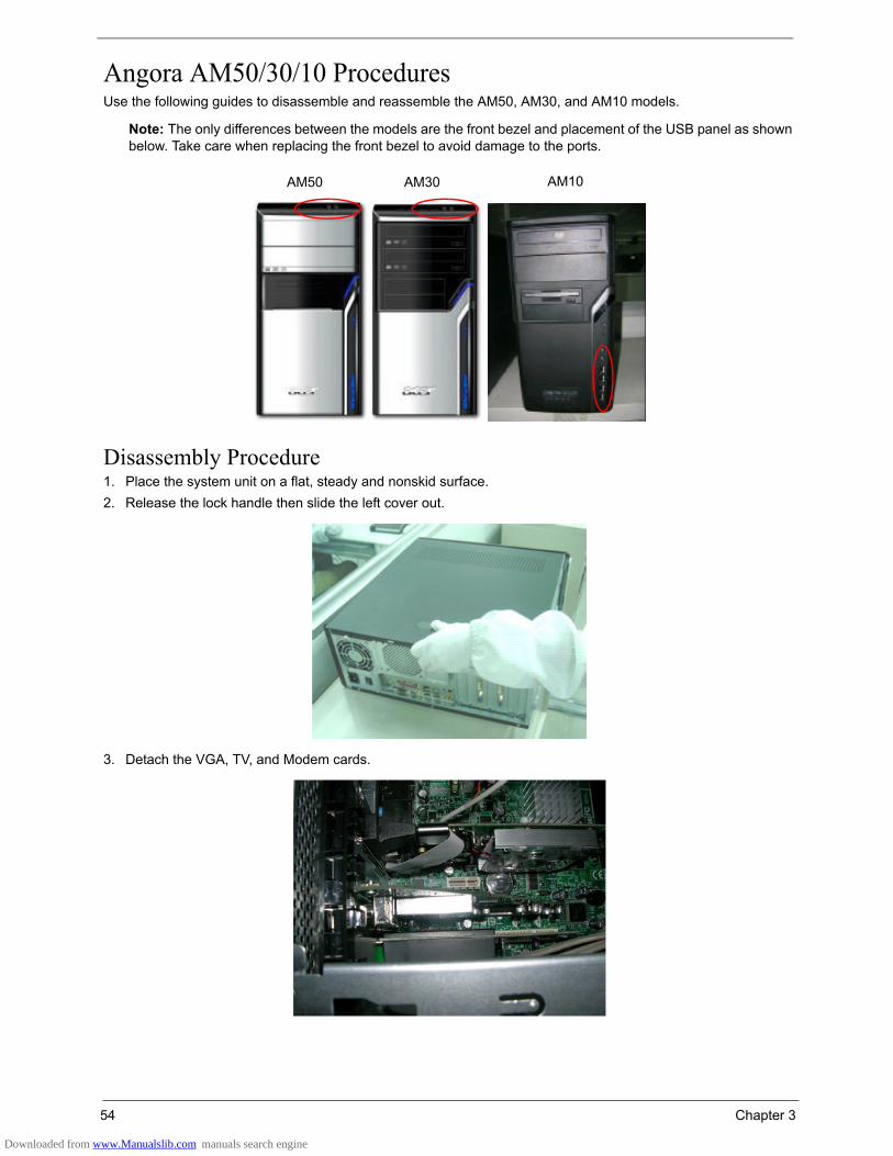
54 Chapter 3
Angora AM50/30/10 ProceduresUse the following guides to disassemble and reassemble the AM50, AM30, and AM10 models.
Note: The only differences between the models are the front bezel and placement of the USB panel as shown below. Take care when replacing the front bezel to avoid damage to the ports.
Disassembly Procedure1. Place the system unit on a flat, steady and nonskid surface.2. Release the lock handle then slide the left cover out.
3. Detach the VGA, TV, and Modem cards.
AM50 AM30 AM10
Downloaded from www.Manualslib.com manuals search engine

Chapter 3 55
4. Disconnect the front bezel LED cable.
5. Disconnect the audio cables.
6. Disconnect the USB cables.
7. Disconnect the SPDIF cable.
Downloaded from www.Manualslib.com manuals search engine
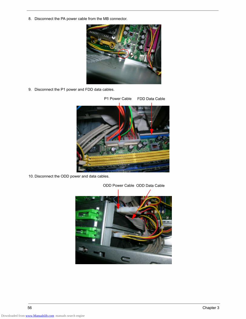
56 Chapter 3
8. Disconnect the PA power cable from the MB connector.
9. Disconnect the P1 power and FDD data cables.
10. Disconnect the ODD power and data cables.
P1 Power Cable FDD Data Cable
ODD Power Cable ODD Data Cable
Downloaded from www.Manualslib.com manuals search engine

Chapter 3 57
11. Disconnect the HDD power and data cables.
12. Disconnect the System Fan and CPU Cooler power cable from their MB connectors.
13. Slide the HDD holder as shown and remove the HDD from the chassis.
CPU Cooler System Fan
Downloaded from www.Manualslib.com manuals search engine
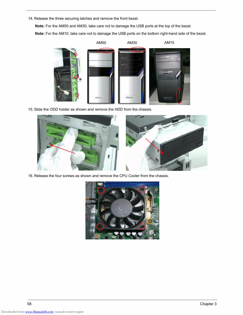
58 Chapter 3
14. Release the three securing latches and remove the front bezel.
Note: For the AM50 and AM30, take care not to damage the USB ports at the top of the bezel.
Note: For the AM10, take care not to damage the USB ports on the bottom right-hand side of the bezel.
15. Slide the ODD holder as shown and remove the HDD from the chassis.
16. Release the four screws as shown and remove the CPU Cooler from the chassis.
AM50 AM30 AM10
Downloaded from www.Manualslib.com manuals search engine
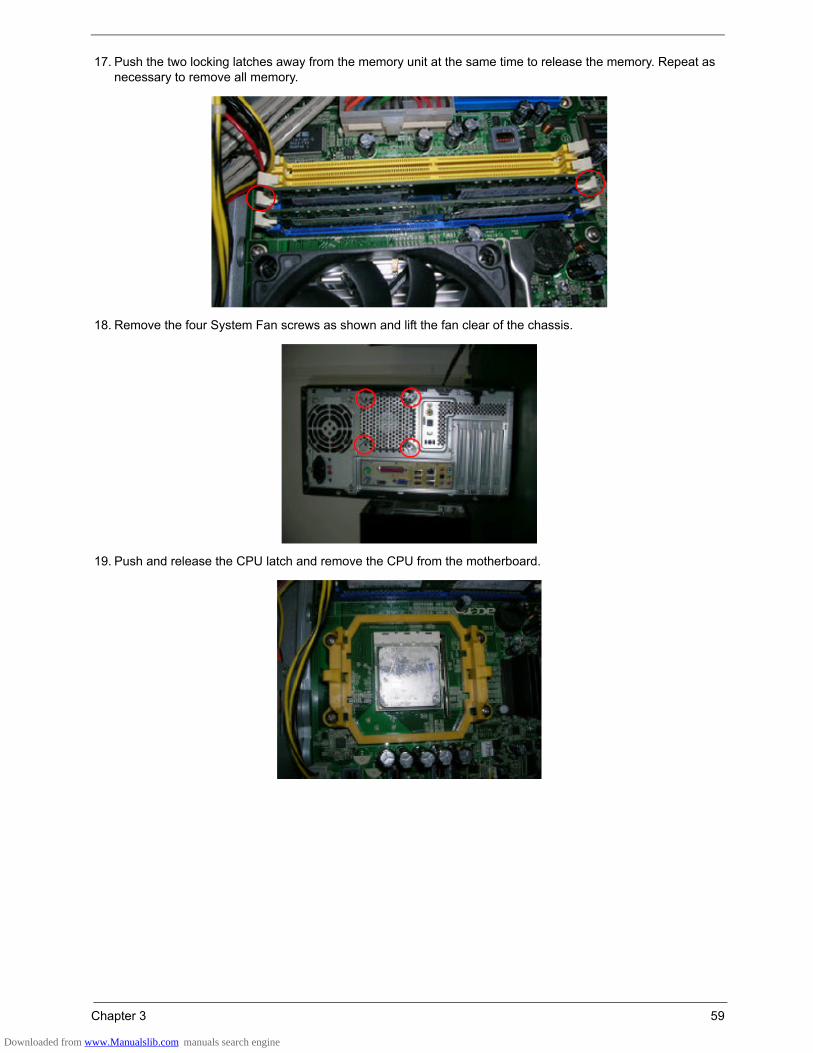
Chapter 3 59
17. Push the two locking latches away from the memory unit at the same time to release the memory. Repeat as necessary to remove all memory.
18. Remove the four System Fan screws as shown and lift the fan clear of the chassis.
19. Push and release the CPU latch and remove the CPU from the motherboard.
Downloaded from www.Manualslib.com manuals search engine
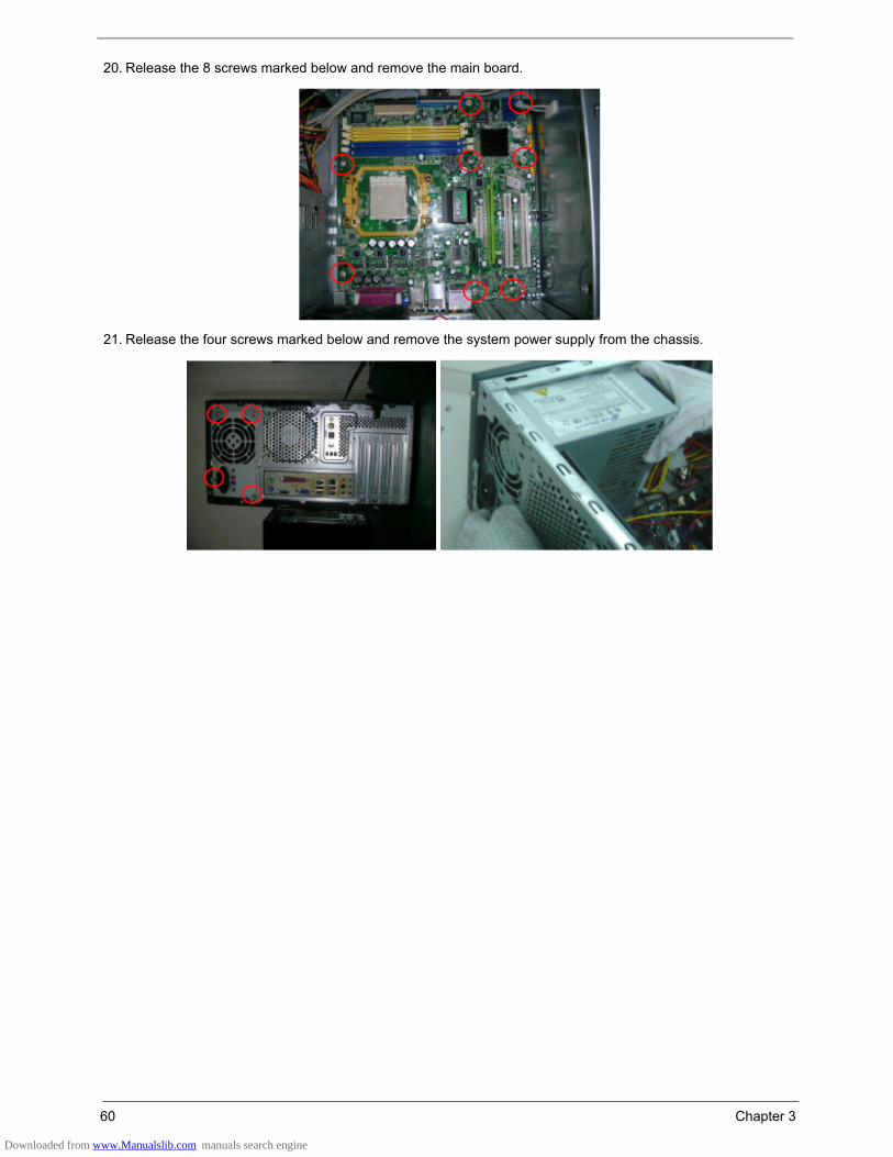
60 Chapter 3
20. Release the 8 screws marked below and remove the main board.
21. Release the four screws marked below and remove the system power supply from the chassis.
Downloaded from www.Manualslib.com manuals search engine
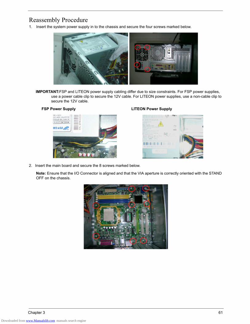
Chapter 3 61
Reassembly Procedure1. Insert the system power supply in to the chassis and secure the four screws marked below.
IMPORTANT:FSP and LITEON power supply cabling differ due to size constraints. For FSP power supplies, use a power cable clip to secure the 12V cable. For LITEON power supplies, use a non-cable clip to secure the 12V cable.
2. Insert the main board and secure the 8 screws marked below.
Note: Ensure that the I/O Connector is aligned and that the VIA aperture is correctly oriented with the STAND OFF on the chassis.
FSP Power Supply LITEON Power Supply
Downloaded from www.Manualslib.com manuals search engine
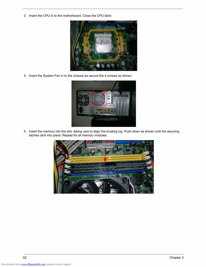
62 Chapter 3
3. Insert the CPU in to the motherboard. Close the CPU latch.
4. Insert the System Fan in to the chassis as secure the 4 screws as shown.
5. Insert the memory into the slot, taking care to align the locating lug. Push down as shown until the securing latches click into place. Repeat for all memory modules.
Downloaded from www.Manualslib.com manuals search engine

Chapter 3 63
6. Fit the CPU cooler to the MB and fasten the four screws shown bellow.
7. Connect the System Fan & CPU Cooler power-cables to the MB connectors.
8. Insert the ODD in to the chassis and slide the ODD holder as shown to lock it in place.
CPU Cooler System Fan
Downloaded from www.Manualslib.com manuals search engine

64 Chapter 3
9. Insert the FDD in to the chassis and slide the FDD holder as shown to lock it in place.
10. Attach the front bezel as shown. Ensure that access to the USB ports is not restricted as indicated for the three models.
11. Insert the SPDIF into the chassis. Ensure that the unit locates correctly as shown.
12. Insert the HDD in to the chassis and slide the HDD holder as shown to lock it in place.
AM50 AM30 AM10
Downloaded from www.Manualslib.com manuals search engine

Chapter 3 65
13. Connect the HDD data cable and HDD power cable.
14. Connect the ODD data cable and power-cable to the rear of ODD.
15. Connect the P1 power-cable and FDD data cable to the MB connector.
ODD Power Cable ODD Data Cable
P1 Power Cable FDD Data Cable
Downloaded from www.Manualslib.com manuals search engine
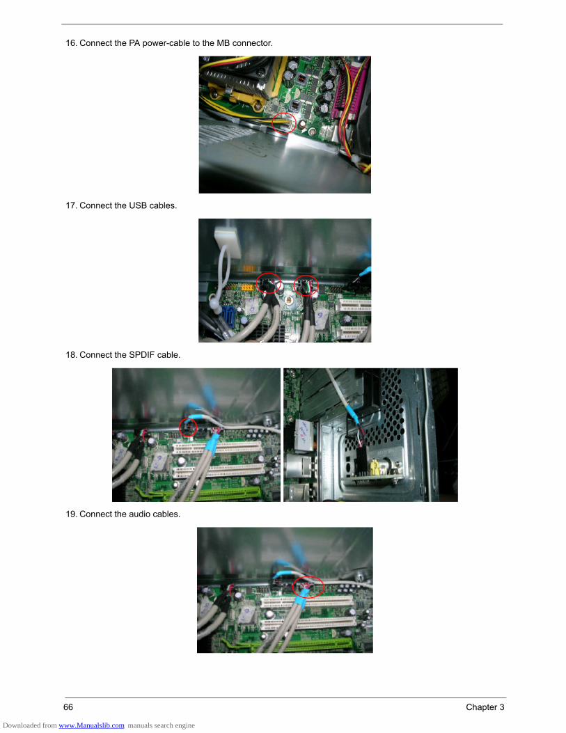
66 Chapter 3
16. Connect the PA power-cable to the MB connector.
17. Connect the USB cables.
18. Connect the SPDIF cable.
19. Connect the audio cables.
Downloaded from www.Manualslib.com manuals search engine

Chapter 3 67
20. Connect the front bezel LED cable.
21. Connect the VGA/TV, and Modem cards.
22. Slide the left cover in and secure the lock handle.
Downloaded from www.Manualslib.com manuals search engine

Chapter 4 69
Please refer to generic troubleshooting guide in the service guide database for information with respect to following items:
• Power-On Self-Test (POST)• POST Check Points• POST Error Messages List• Error Symptoms List
Troubleshooting
Chapter 4
Downloaded from www.Manualslib.com manuals search engine
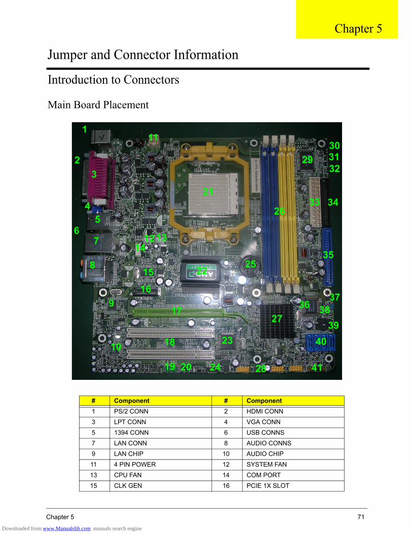
Chapter 5 71
Introduction to Connectors
Main Board Placement
# Component # Component1 PS/2 CONN 2 HDMI CONN
3 LPT CONN 4 VGA CONN
5 1394 CONN 6 USB CONNS
7 LAN CONN 8 AUDIO CONNS
9 LAN CHIP 10 AUDIO CHIP
11 4 PIN POWER 12 SYSTEM FAN
13 CPU FAN 14 COM PORT
15 CLK GEN 16 PCIE 1X SLOT
1
3
4
2
8
5
76
10
9
41
131214
4039
373836
35
3433
303132
29
28
27
26
25
24
23
22
21
11
1516
17
18
19 20
Chapter 5
Jumper and Connector Information
Downloaded from www.Manualslib.com manuals search engine

72 Chapter 5
17 PCIE 16X SLOT 18 PCI SLOTS
19 FRONT AUDIO HEADER 20 AUX_IN HEADER
21 CPU SOCKET 22 NORTH BRIDGE
23 1394 CHIP 24 FRONT 1394 HEADER
25 BATTERY 26 DIMM SLOTS
27 SOUTH BRIDGE 28 FRONT USB HEADER
29 SI/O CHIP 30 AS HEADER 2
31 AS HEADER 1 32 INTR HEADER
33 24 PIN POWER 34 FLOPPY CONN
35 IDE CONN 36 BIOS
37 CLR_CMOS HEADER 38 OBR HEADER
39 SPEAKER HEADER 40 SATA CONN
41 FRONT PANEL
Downloaded from www.Manualslib.com manuals search engine
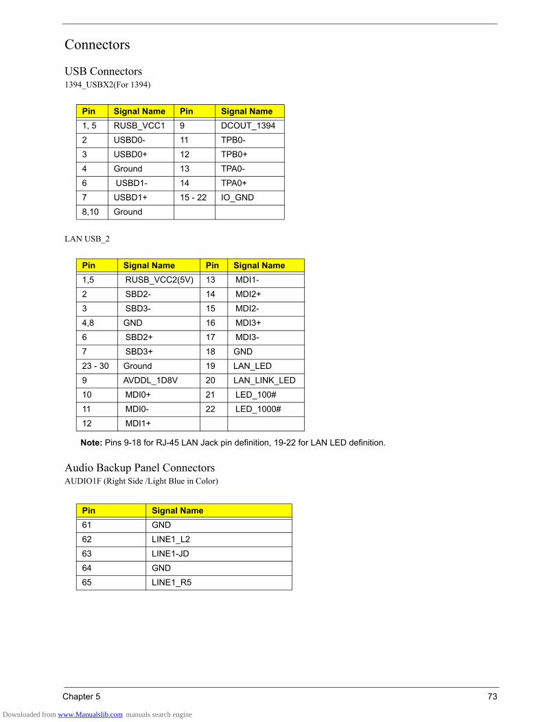
Chapter 5 73
Connectors
USB Connectors1394_USBX2(For 1394)
LAN USB_2
Note: Pins 9-18 for RJ-45 LAN Jack pin definition, 19-22 for LAN LED definition.
Audio Backup Panel ConnectorsAUDIO1F (Right Side /Light Blue in Color)
Pin Signal Name Pin Signal Name1, 5 RUSB_VCC1 9 DCOUT_1394
2 USBD0- 11 TPB0-
3 USBD0+ 12 TPB0+
4 Ground 13 TPA0-
6 USBD1- 14 TPA0+
7 USBD1+ 15 - 22 IO_GND
8,10 Ground
Pin Signal Name Pin Signal Name1,5 RUSB_VCC2(5V) 13 MDI1-
2 SBD2- 14 MDI2+
3 SBD3- 15 MDI2-
4,8 GND 16 MDI3+
6 SBD2+ 17 MDI3-
7 SBD3+ 18 GND
23 - 30 Ground 19 LAN_LED
9 AVDDL_1D8V 20 LAN_LINK_LED
10 MDI0+ 21 LED_100#
11 MDI0- 22 LED_1000#
12 MDI1+
Pin Signal Name61 GND
62 LINE1_L2
63 LINE1-JD
64 GND
65 LINE1_R5
Downloaded from www.Manualslib.com manuals search engine

74 Chapter 5
AUDIO1E (Right Side /FRONT Lime in Color)
AUDIO1D (Right Side /Pink in Color)
AUDIO1A (Left Side/Gray in Color)
AUDIO1C (Left Side, Orange in Color)
AUDIO1D (Left Side, Black in Color)
Pin Signal Name51 GND
52 LINE_OUT_L2
53 FRONT-JD
54 GND
55 LINE_OUT_R5
Pin Signal Name41 GND
42 MIC1_L2
43 MIC1-JD
44 GND
45 MIC1_R5
Pin Signal Name1 GND
2 SIDESURRBACK_L2
3 SIDESURR-JD
4 GND
5 SIDESURRBACK_R2
Pin Signal Name31 GND
32 CEN-C
33 CEN-JD
34 GND
35 LFE-C
Pin Signal Name21 GND
22 SURR_L
23 SURR-JD
24 GND
25 SURR_R
Downloaded from www.Manualslib.com manuals search engine

Chapter 5 75
IDE/SATA40-pin (2x20) PIDE Headers
1x7-pin SATA Headers
Pin Signal Name Pin Signal Name1 HD_RST# 2 Ground
3 PDD7 4 PDD8
5 PDD6 6 PDD9
7 PDD5 8 PDD10
9 PDD4 10 PDD11
11 PDD3 12 PDD12
13 PDD2 14 PDD13
15 PDD1 16 PDD14
17 IPDD0 18 PDD15
19 Ground 20 Key
21 PD_REQ 22 Ground
23 PD_IOW# 24 Ground
25 PD_IOR# 26 Ground
27 PD_RDY 28 Ground
29 PD_ACK# 30 Ground
31 IRQ14_R 32 N/C
33 PD_A1 34 PD_DET
35 PD_A0 36 PD_A2
37 PD_CS1# 38 PD_CS3#
39 IDE_LED# 40 Ground
Pin Signal Name1 GND
2 SATA_TX0+_C
3 SATA_TX0-_C
4 GND
5 SATA_RX0-_C
6 SATA_RX0+_C
7 GND
8 KEY
9 KEY
Downloaded from www.Manualslib.com manuals search engine

76 Chapter 5
VGA
HDMI
Pin Signal Name Pin Signal Name1 CONN_RED 9 5V_DVI
2 CONN_GREEN 10 GND
3 CONN_BLUE 11 GND
4 GND 12 CONN_DAC_SDAT
5 GND 13 CONN_HSYNC#
6 GND 14 CONN_VSYNC#
7 GND 15 CONN_DAC_SCL
8 GND
Pin Signal Name Pin Signal Name1 HDMI_TXAP2 12 HDMI_TXCAN
2 GND 13 NC
3 HDMI_TXAN2 14 NC
4 HDMI_TXAP1 15 HDMI_DDC_CLK
5 GND 16 HDMI_DDC_DATA
6 HDMI_TXAN1 17 GND
7 HDMI_TXAP0 18 5V_S0
8 GND 19 HDMI_HOT_PLUG_DETECT
9 HDMI_TXAN0 20 GND
10 HDMI_TXCAP 21 GND
11 GND
Downloaded from www.Manualslib.com manuals search engine

Chapter 5 77
JumpersJumper/Header Name Function DefinitionCPUFAN (3 PIN) CPU FAN HEADER
Yellow is symbol, Red is Pin1 of symbol
1: GND
2: POWER
3: SENSE
SYSFAN (3 PIN) SYSTEM FAN HEADER
Yellow is symbol, Red is Pin1 of symbol
1: GND
2: POWER
3: SENSE
CLR_CMOS (3 PIN) CLEAR CMOS HEADER
Yellow is symbol, Red is Pin1 of symbol
1,2: CLEAR CMOS(1: Ground, 2: RTC_RSTJ)
2,3: NORMAL(3: VCC_RTC)
OBR System Recover HEADER
Yellow is symbol, Red is Pin1 of symbol
1: SYS_RECOVER
2: GND
Downloaded from www.Manualslib.com manuals search engine
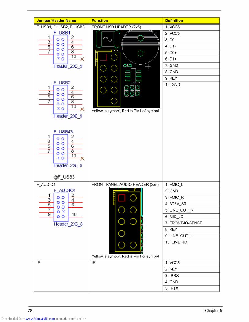
78 Chapter 5
F_USB1, F_USB2, F_USB3 FRONT USB HEADER (2x5)
Yellow is symbol, Red is Pin1 of symbol
1: VCC5
2: VCC5
3: D0-
4: D1-
5: D0+
6: D1+
7: GND
8: GND
9: KEY
10: GND
F_AUDIO1 FRONT PANEL AUDIO HEADER (2x5)
Yellow is symbol, Red is Pin1 of symbol
1: FMIC_L
2: GND
3: FMIC_R
4: 3D3V_S0
5: LINE_OUT_R
6: MIC_JD
7: FRONT-IO-SENSE
8: KEY
9: LINE_OUT_L
10: LINE_JD
IR IR 1: VCC5
2: KEY
3: IRRX
4: GND
5: IRTX
Jumper/Header Name Function Definition
Downloaded from www.Manualslib.com manuals search engine
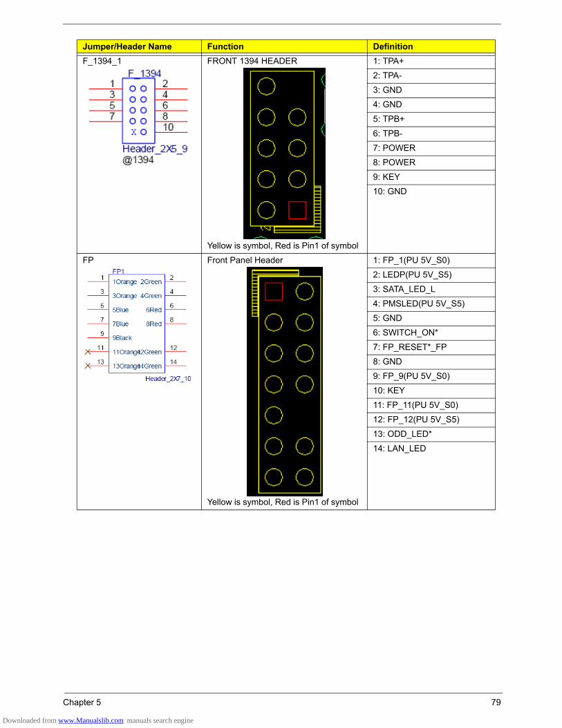
Chapter 5 79
F_1394_1 FRONT 1394 HEADER
Yellow is symbol, Red is Pin1 of symbol
1: TPA+
2: TPA-
3: GND
4: GND
5: TPB+
6: TPB-
7: POWER
8: POWER
9: KEY
10: GND
FP Front Panel Header
Yellow is symbol, Red is Pin1 of symbol
1: FP_1(PU 5V_S0)
2: LEDP(PU 5V_S5)
3: SATA_LED_L
4: PMSLED(PU 5V_S5)
5: GND
6: SWITCH_ON*
7: FP_RESET*_FP
8: GND
9: FP_9(PU 5V_S0)
10: KEY
11: FP_11(PU 5V_S0)
12: FP_12(PU 5V_S5)
13: ODD_LED*
14: LAN_LED
Jumper/Header Name Function Definition
Downloaded from www.Manualslib.com manuals search engine
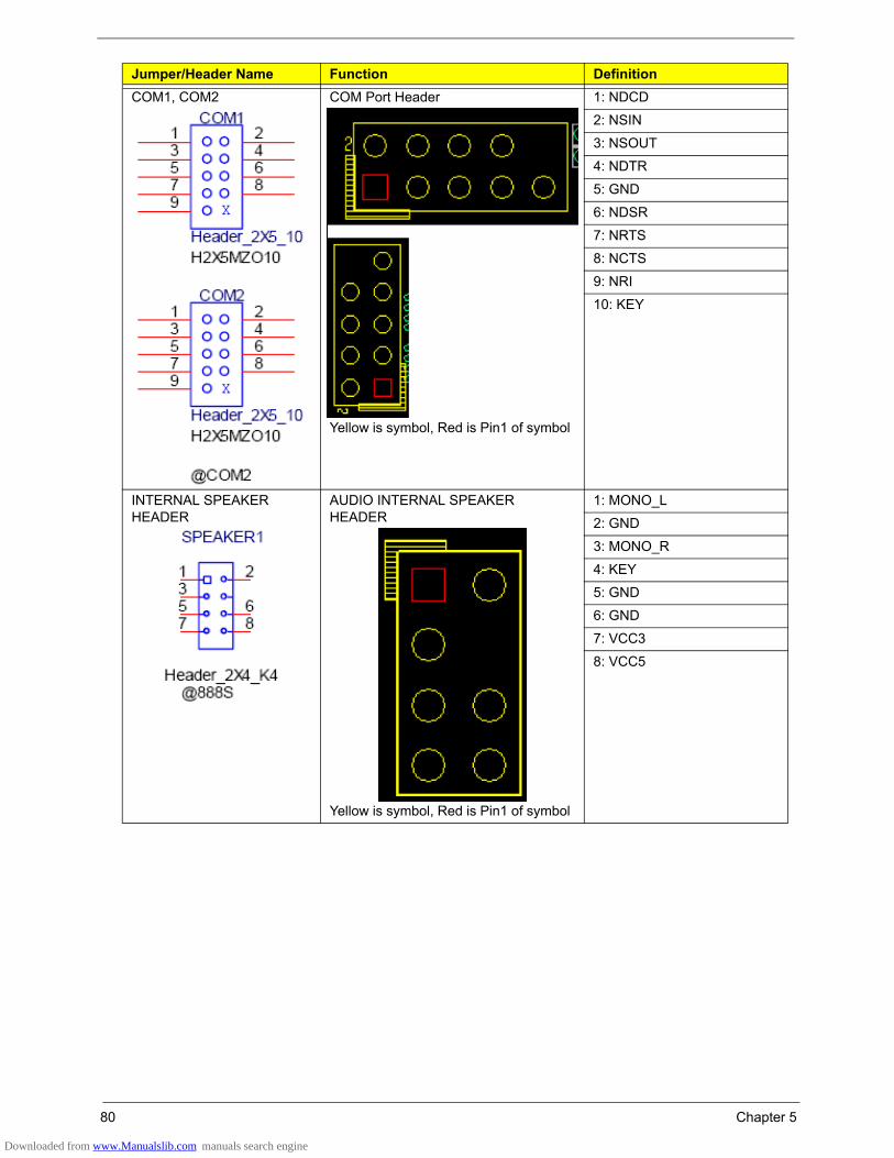
80 Chapter 5
COM1, COM2 COM Port Header
Yellow is symbol, Red is Pin1 of symbol
1: NDCD
2: NSIN
3: NSOUT
4: NDTR
5: GND
6: NDSR
7: NRTS
8: NCTS
9: NRI
10: KEY
INTERNAL SPEAKER HEADER
AUDIO INTERNAL SPEAKER HEADER
Yellow is symbol, Red is Pin1 of symbol
1: MONO_L
2: GND
3: MONO_R
4: KEY
5: GND
6: GND
7: VCC3
8: VCC5
Jumper/Header Name Function Definition
Downloaded from www.Manualslib.com manuals search engine

Chapter 5 81
TPM TPM HEADER
Yellow is symbol, Red is Pin1 of symbol
1: LCKL
2: GND
3: LFRAMEn
4: KEY
5: LRESETn
6: NC
7: LAD3
8: LAD2
9: VDD (3.3V)
10: LAD1
11: LAD0
12: GND
13: NC
14: NC
15: NC
16: SERIRQ
17: GND
18: CLKRUNin
19: LPCPDn
20: NC
Jumper/Header Name Function Definition
Downloaded from www.Manualslib.com manuals search engine

Chapter 6 83
This chapter offers the FRU (Field Replaceable Unit) list in global configuration of Angora AM5610 and AM3610 desktop. Refer to this chapter whenever ordering the parts to repair or for RMA (Return Merchandise Authorization).
Please note that when ordering FRU parts, you should check the most up-to-date information available on your regional web or channel. For whatever reasons a part number is changed, it will NOT be noted on the printed service guide. For Acer authorized service providers, your Acer office may have a different part number code from those given in the FRU list of this printed service guide. You MUST use the local FRU list provided by your regional Acer office to order FRU parts for service.
Note: To scrap or to return the defective parts, you should follow the local government ordinance or regulations on how to dispose them properly, or follow the rules set by your regional Acer office on how to return it.
Chapter 6
FRU (Field Replaceable Unit) List
Downloaded from www.Manualslib.com manuals search engine
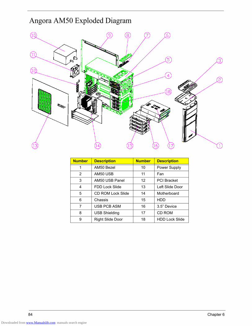
84 Chapter 6
Angora AM50 Exploded Diagram
Number Description Number Description1 AM50 Bezel 10 Power Supply
2 AM50 USB 11 Fan
3 AM50 USB Panel 12 PCI Bracket
4 FDD Lock Slide 13 Left Slide Door
5 CD ROM Lock Slide 14 Motherboard
6 Chassis 15 HDD
7 USB PCB ASM 16 3.5” Device
8 USB Shielding 17 CD ROM
9 Right Slide Door 18 HDD Lock Slide
Downloaded from www.Manualslib.com manuals search engine

Chapter 6 85
Angora AM30 Exploded Diagram
Number Description Number Description1 AM30 Main Bezel 11 Fan
2 3_25 Cover 12 PCI Bracket
3 5_25 Cover 13 Left Side Door
4 AM50 USB 14 Motherboard
5 AM50 USB Panel 15 HDD
6 Chassis 16 3.5” Device
7 USB PCB ASM 17 CD ROM
8 USB Shielding 18 HDD Lock Slide
9 Right Side Door 19 FDD Lock Slide
10 Power Supply 20 CD ROM Lock Slide
Downloaded from www.Manualslib.com manuals search engine

86 Chapter 6
Angora AM10 Exploded Diagram
Number Description Number Description1 AM10 Main Bezel 10 Power Supply
2 3_25 Cover 11 Fan
3 5_25 Cover 12 PCI Bracket
4 AM50 USB 13 Left Side Door
5 AM50 USB Panel 14 Motherboard
6 FDD Lock Slide 15 HDD Lock Slide
7 CD ROM Lock Slide 16 HDD
8 Chassis 17 3.5” Device
9 Right Side Door 18 CD ROM
Downloaded from www.Manualslib.com manuals search engine

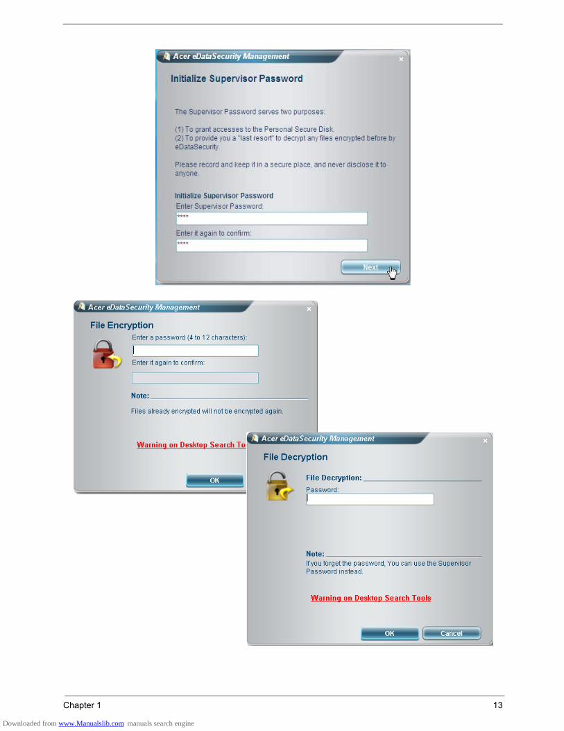


![Acer Aspire 5930G[1]](https://static.documents.pub/doc/80x56/54800cfcb37959892b8b5ad6/acer-aspire-5930g1.jpg)