

Page 1 of 27
C2005RVNLStSpecifications 15th Febrsquo06 ADDENDUMCORRIGENDUM SLIP NO1 DATED 150206 TO
RVNL STANDARD SPECIFICATIONS FOR MATERIALS AND WORKSrdquo
SNo Reference of Clause No
Details of CorrigendumAddendum to clause under reference
1 SampT Works VolIII Page 4 of 61 Clause 33
Clause 33 is modified as under- ldquoA list of technical specification and drawings have been prepared and annexed as Annexure A-1 for following the details of purchases of material equipments and execution of work These technical specifications and drawings can be purchased from the sources mentioned in the Annexure A-1 List of major constructionequipments drawings for signaling other than RDSO drawings are given in Annexure A-2rdquo The copies of Annexures A-1 and A-2 are enclosed with this Corrigendum
2 SampT Works VolIII Page 8 of 61 Clause 48
Annexure bdquoB‟ appearing in last sub para of Clause 48 is enclosed
3 SampT Works VolIII Page 16 of 61 Clause 98
The DrgNo RVNLSampTSG-0372005 to be read as RVNLSampTSG-0332005 Also in the same para DrgNo RVNLSampTSG-0352005 should be read as RVNLSampTSG-0322005
4 SampT Works VolIII Page 18 of 61 New Clause 1012
Add Clause No1012 after Clause No1011 as under 1012 All signals are to be earthed as per RE standard in RE area
5 SampT Works VolIII Page 24 of 61 New Clause 1518
Add Clause 1518 after Clause No 1517 as follows 1518 Audio Frequency Track Circuits)(AFTC) 15181 AFTC track circuits shall be provided as per RDSO specification NoRDSOSPN1462001 with latest amendments 15182 Only coded AFTC track circuits shall be provided
Page 2 of 27
15183 Frequencies and code selection shall be made in a suitable manner so that they are not repeated in the same yard 15184 AFTC track circuits shall be suitable for 25 KV Railway Electrification 15185 These track circuits shall be operated with 230 Volts AC supply 15186 Separate 46 quad telecommunication cables shall be used for transmitter and receiver frequencies for the same track circuit
6 SampT Works VolIII Page 25 of 61 Clause 163
At the end of last sentence of the para add words in RE area
7 SampT Works VolIII Page 26 of 61 Clause 171
The first sentence of the Clause is modified as under Cable termination racks as per drawing RVNLSampTSG-0562005 shall be erected in the relay room at the required location as shown by the Railway with suitable foundation bolts and cement concreted
8 SampT Works VolIII Page 27 of 61 Clause 181
Clause 181 is replaced as under 181 Relay rack frame to accommodate 1 way relay rack is to be fabricated as per RVNL Drg No RVNL SampT sg-0552005 The frame is held rigidly by the base assembly and electrically isolated by insulator vertical supporting angle of 65mm X 65mm X 8mm and bottom and top frame angle of 45mm X 45mm X 6mm Relay rack is to be fabricated out of 65mm X 65mm X 2200mm angles in vertical position spaced 530 mm apart by the flats one at the top and the other at the bottom welded to the angle The relay racks are fitted to the angle frame by 20 X 75mm bolts with washers and spring washers
9 10
SampT Works VolIII Page 34 of 61 Clause 220 SampT Works VolIII Page 34 of 61 Clause 221
The heading ldquoSSI systemrdquo is replaced with ldquoEI Systemrdquo and in its sub paras whereas words SSI appears is to be read as EI In second line of the Clause 221 the RDSO specification No RDSOSPN1022004 to be read as RDSOSPN1922005
Page 3 of 27
11 12 13
SampT Works VolIII Page 34 of 61 Clause 222 (b) SampT Works VolIII Page 35 of 61 Clause 222(d) SampT Works VolIII Page 35 of 61 Clause 224
At the end of Clause 222(b) add ManufacturerSupplierContractor shall ensure that after the end of 10th year a minimum notice period of 3 years is given to Railways before discontinuing the production of the model so that the Railway can purchase life time spares The word bdquoquantity appearing in Ist line to be replaced with quality Replace Clause 224 as under- 224 WARRANTY
2241 The contractor shall warranty that all materials amp equipment to be supplied and installed as per this tender shall be free from defects and faults in design material workmanship and manufacture and shall be of the highest grade and consistent with established and generally accepted standard for materials of the type ordered and in full conformity with the contract specification
2242 This warranty shall start from the
date of commissioning and shall expire 1 year (12 months) after commissioning The contractor shall be responsible for the proper functioning of the system during the period of warranty
2243 During the period of warranty the Contractor shall remain responsible to arrange replacement and for setting right at his own cost any equipment supplied by him which is of defective manufacture or defective design or defective material component or becomes unworkable due to any cause whatsoever
Page 4 of 27
14
SampT Works VolIII Page 35 of 61 New Clause 225
2244 If it becomes necessary for the contractor to replace or renew any defective portions of the system under this clause the provision of this clause shall apply to the expiry of six months from the date of such replacement or renewal or until the end of the warranty period whichever may be later If any defect is not remedied within reasonable time the Railway may proceed to do the work at Contractor‟s risk and expenses but without prejudice to any other rights which the Railway may have against the Contractor in respect of such defects
2245 Inspections clauses for replacements or renewals carried out by the Contractor during the warranty period shall be the same as provided in the conditions of the contract for the work
2246 All replacement and repairs and
design change that the Railway shall call upon the contractor to deliver or perform under this warranty shall be delivered and performed by the contractor within one month promptly and satisfactorily
2247 The decision of the Railway in regard
to Contractor‟s liability under this warranty shall be final and conclusive
2248 Due to analysis of failures if any
design deficiency is pointed out by the Railway the contractor shall rectify it at his own cost
Add Clause 225 after Clause 224 as under
Page 5 of 27
225 ANNUAL MAINTENANCE CONTRACT ( 2251 Tenderer should quote separately for Annual
Maintenance Contract(AMC) charges for the equipment per year for a period of 1 (one) year which shall be considered for evaluation of the Tender The rate quoted for the AMC will be binding for 3 (Three) years after the warranty period A separate agreement will be entered into for the AMC between ManufacturerSupplierContractor and Southern railway Railway on its discretion may enter into AMC for a lesser period or may not enter into the AMC at all
2252 During the AMC period Manufacturer
SupplierContractor will be responsible for the rectification of defective modules replacement of defective module by a new one for restoration of the system Spare module if available with railways may be utilized for the restoration In such a situation the Manufacturer SupplierContractor shall be liable to return the repaired new module to railways within 72 hours of handing over the defective modules at their premises No additional charges shall be payable for such repairreplacement works ManufacturerSupplier Contractor‟s trained staff shall quarterly visit the installation to monitor the proper functioning of the system as well as preventive maintenance of the system During this period he shall provide required guidance to the railway maintenance staff as well as preventive maintenance of the system ManufacturerSupplierContractor should also give free services by way of rectifying design defects in the hardwaresoftware including up-gradationmodification to take care of the deficiencies noticed while in service
15
SampT Works VolIII Page 40 of 61 Clause 312
Replace Clause 312 as under- 312 The work includes excavation of a pit at a given
location as per Drg No RVNLSampTSG-0332005 on natural soil fixing earth pipe covering the same with a mixture of 2 Kg of charcoal 2 Kg Of common salt and earth This includes brick masonry around the earth
Page 6 of 27
16
SampT Works VolIII Page 41 of 61 Clause 313
GI pipe of size 50mm X 3 M with 12mm dia holes on the sides at intervals of 300mm shall be used as earthing electrode The equipments to be earthed shall be connected to the earth pipe through earthing bonds (20mm flexible insulated hot dipped galvanized multistrand with copper lugs precrimped on both ends) by welding pin brazing method One end of the bond shall be connected to the earth electrode and the other end to the signaling equipment (Block Instrument lightening arrestor cable sheath power equipment apparatus cases relay racks etc as per specification IRS S-103-2004 and instructions of engineer Earth resistance shall be measured and painted on the earth piped with date The earth resistance shall not be more than 10 ohms (for electronic equipment it shall be as prescribed by the manufacturer manual whichever is less)
Replace Clause 313 as under 313 EARTHING OF EI Earthing of EI equipment and room shall be done as per Drg NoRVNLSampTSG -0362005 Relay room shielding shall be provided as per DrgnoRVNLSampTSG-0382005 and electrode burial arrangement shall be as per Drgno RVNLSampTSG-0372005 at EI station
17 SampT Works VolIII Page 42 of 61 Clause 340
Heading of Clause to be changed as under ldquoAXLE COUNTER FOR BLOCK PROVING ldquo
18 SampT Works VolIII Page 61 of 61 New Clause 410
Add New Clause 410 at the end after Clause 400 410 Automatic Permissive Block (APB) ndash Refer
Annexure C for Indian Railways General Rules
411 Single Line sections working on Automatic
Block Working after establishing direction of movement are known as Automatic Permissive Block (APB)
412 The block section shall be split into two or more
sub sections so that more than one train can follow in the same direction
Page 7 of 27
413 The block section shall be fully track circuited or each sub section is provided with Axle counters to detect the passage of train for each signal
414 Inter signal distances between the two signals
in the same direction shall generally be one Km where as main berthing track shall not be less than 690 meters (Distance to hold a full length freight train)
415 Four aspect signals shall be used The aspect
control shall be lsquoRED-YELLOW-DOUBLE YELLOW-GREENrsquo A distance of two Kms shall be ensured between Double Yellowrsquo signal aspect to lsquoREDrsquo signal aspect to provide full braking distance In case this distance is less then the previous signal instead of showing lsquoGreenrsquo aspect shall also show lsquoDouble Yellowrsquo aspect
416 System of Working
1) When there is no train in the Block section between the two stations the controlling Panels of the Station Masters on either side shall show lsquoSECTION CLOSEDrsquo All the signals in this condition in the block section shall show lsquoREDrsquo aspect
2) When any Station Master proposes to send a train he shall seek line clear from the other Station Master and if agreed both of them will simultaneously operate their panels as specified for obtaining Line Clear The sending station shall get Line Clear Indication on his Control panel as lsquoTrain Going TOrsquo and the receiving Station Master shall get the indication on his Panel as lsquoTrain Coming Fromrsquo
3) Before the Line Clear Indication is displayed
on the controlling panels the system shall automatically check that all the track circuits in the block section are picked up and there is no train in the block section
4) If conditions of line clear are met with then
all the signals in the section in the direction so established shall display lsquoGreenrdquo aspect subject to the condition that respective LC gates in the specific signalrsquo jurisdiction is
Page 8 of 27
closed The opposing signals in the block section shall show lsquoREDrsquo aspect When a train enters block sections the TOL indication shall appear on the panels automatically
5) Trains can follow one after the other in the
same direction and all the signals shall work as fully automatic with the passage of trains
6) When it is desired to reverse the direction of
movement the either end Station Masters after confirming that Block section is clear of all trains they shall jointly operate their control panel and close the Block section The system shall check that before closing of the Block section all the controlling track circuits in the Block section are clear of all trains and at station receiving the trains concerned reception and dispatch signals are at on Once the Block section is closed the direction of traffic can be established as per requirement by the Station Masters as explained above
7) In case the section does not clear due to failure of track circuit or any other system failure the block section shall work on lsquoAbsolute Blockrsquo principles by following laid down rules till the normal system is restored
417 Working of Level Crossing Gates in APB Section
1) All level crossing gates in the APB section
shall be manned and fully interlocked with the signals
2) The Gate signals shall display lsquoREDrsquo aspect
if the LC gate is open The road signals for the level crossing gate show lsquoClearrsquo for passage of road traffic
3) The controlling Signals for LC Gate shall be
provided with Lit lsquoAGrsquo marker If the Gate is opened this lsquoAGrsquo marker shall not be lit and the train has to cross the same following normal rules of passing a Gate signal at lsquoONrsquo Incase the gate is closed the lsquoAGrsquo marker shall be lit and the train shall pass
Page 9 of 27
the signal in accordance with rules for passing automatic signal
4) All gates shall be provided with audio visual
lsquoApproach Warningrsquo from a predetermined location This location shall not be less than four Kms This distance shall be sufficient to enable Gate keeper to close the LC gate and clear the signals for the approaching train so that the Approaching train gets lsquoClearrsquo signal from the LC gate and does not slow down In case the LC gate is located less than 4 Kms from the station the pre-warning for LC gate shall be given when the Last stop signal of the station has been taken lsquoOFFrsquo
5) The moment Approach warning is received
at the LC gate it shall also give audio visual warning for the road user also so that road traffic stops
Page 10 of 27
Annexure A-1
SPECIFICATIONS OF SIGNALLING ITEMS 1 Electronic Interlocking System (EI) as per RDSO specification
RDSOSPN1922005 2 Integrated Power Supply (IPS) System as per RDSO Specification
No RDSOSPN1652000 with latest amendments 3 Electric Point Machine working on 110V DC heavy duty non-
trailable rotary locking type complete as per IRS-S-242002 amp Drg NoS-10910 with clamp lock arrangement as per RDSO drawing no S-11000
4 Data Logger as per Specification No IRS S-992001 5 OperationIndication panel as per Specification No IRS S-3687 or
latest 6 LED Signal Unit as per Specification NoRDSOSPN1532002 with
latest amendments 7 Single Section Digital Axle Counter as per RDSO Specification
NoRDSOSPN1772003 ver1 with latest amendment 8 Un-screened PVC insulated Armoured signalling cable Copper conductor
solid stranded as per specification NoIRS-S-6389 with latest amendments The core of the cable shall be identified as per Para 325326 of the specification
9 Jelly filled cables as per specification IRS-TC-41-97 with latest amendment 10 Four quadSix quad having 05 mm dia or 09 mm dia conductors
underground cable for Axle counterAFTC for use in Railway Electrified areas as per IRS TC-3097 or (Latest)
11 Indoor cables copper conductor PVC insulated and sheathed as per IRS S7689 with latest amendments
12 Single core solidstranded Copper conductor PVC insulated coloured as per IRS S7689 with latest amendments
13 Apparatus case steel single as per drawing No RVNLS amp TSG-0112005 with alteration lsquoArsquo and 22182 with alteration lsquoBrsquo (E type lock on both sides)
14 Apparatus case steel half as per drawing No RVNLS amp TSG-0112005 with alteration lsquoArsquo and 22182 with alteration lsquoBrsquo (E type lock on both sides)
15 Junction box steel as per sketch NoRESampTALDSK22782 corrected up to 30686 and 22882 corrected up to 18193 The key and handle should be one each per 2 junction boxes
16 Track lead Jn Box as per IRS(s) Drg NoSA-20101M made of FRP material (FRP material conforming to RDSO SPN 15197 or latest) complete with 450 mm long 25 mm dia pipe
17 Signal colour light Multi Unit type 4 aspect without side light signal transformers lamps and lenses as per RDSO Drg NoSA-23001 AM(Adv) specification IRSS-2664 or latest
18 Signal Colour light multi unit type 3 aspects without side light lenses lamps and signal transformers as per RDSO Drg NoSA-23002 AM (Adv) latest specification IRS S-2664 or latest
19 Signal colour light multi unit type 2 Aspect without side light lenses lamps and signal transformer as per RDSO Drg NoSA-23003 AM (Adv)
Page 11 of 27
latest The mounting socket should be provided for 140 mm dia to RDSO Drg NoS-23005 M (Adv) Latest Specification IRS S-2664 or latest
20 Calling on signal unit as per specification no IRS S-2388 or latest 21 Foundation for main CLS Signal as per drawing no RVNLSampTSG-
0012005 22 Foundation for shunt signal as per drawing no RVNLSampTSG-0022005 23 Foundation for SLBBSLBSB as per drawing no RVNLSampTSG-0082005 24 APGC Markers as per drawing no RVNLSampTSG-0502005 25 Colour Light signalling tubular post as per IRS Spec NoIRS-S-6-81 or
latest 36 metres long 26 Colour Light signalling tubular post as per IRS specNoIRSS-6-81 or
latest 46 metres long 27 Colour Light signalling tubular post as per IRS spec NoIRSS-6-81 or latest
56 metres long 28 Route Indicator directional type 5 units Arm 1 way as per Drg NoSA-
23401 (Adv) latest amp spec IRSS-66 (latest) complete with fittings but without lamps lenses and signal transformer along with mounting sockets 140mm dia to RDSO Drg NoS-23005M (Adv) Latest
29 Route Indicator Directional type 5 Unit Arm 2 way as per Drg NoSA-23402 (Adv) latest amp spec IRSS-66(latest) complete with fittings but without lamps lenses and signal transformer along with mounting sockets 140mm dia to RDSO Drg NoS-23005M (Adv) Latest
30 Route Indicator Directional type 5 Unit Arm 3 way as per Drg NoSA-23403 (Adv) latest amp spec IRSS-66 (latest) complete with fittings but without lamps lenses and signal transformer along with mounting sockets 140mm dia to RDSO Drg NoS-23005M(Adv) Latest
31 Signal lamps ndash Holder unit as per Drg NoS-23030M amp SA-24831 32 Ladder for colour light signal multi unit type 55 metres as per RDSO Drg
NoSA-23156 (Adv) with latest alteration 33 Ladder for colour light signal multi unit type 45 metres as per RDSO Drg
NoSA-23153 (Adv) with latest amendments 34 Ladder for colour light signal multi unit type 35 metres as per RDSO Drg
NoSA-23150 (Adv) with latest amendments 35 Signal Base for 140 mm dia post as per IRS(s) Drg NoS-2011M with
latest amendments 36 Signal Bracket colour position light for 140 mm outside dia post as per
RDSO Drg NoSA-23080 (Adv) latest 37 OFF set Bracket Suitable for colour light signal 140 mm outside dia post 38 lsquoPrsquo Marker (Non-illuminated) as per Drg No RESampTSigTenderSK 36 85
dated 200485 39 Signal Cable Marker as per Drg No RVNLS amp T SG-0222005 40 Block SectionShunting Limit Board as per RDSO DrgNoSA-2373 (Adv)
latest 41 Cable Trough (GI) for girder Bridges as per Drg No RE SampT SIG Tender
SK2285 dt 200485 42 Earth electrode as per Drg No RVNLS amp T SG-0322005 43 Casting of foundation for electrode as per Drg No RVNLS amp T SG-
0332005 44 Earthing of EI equipment as per Drg No RVNLS amp T SG-0362005 45 Electrode burial as per Drg No RVNLS amp T SG-0372005
Page 12 of 27
46 Earthing of Relay Room shielding as per Drg No RVNLS amp T SG-0382005
47 RCC pipe 150 mm dia 2 metre long with collars to IS specn No4581971 or latest
48 Signal shunt position light 2 position as per RDSO Drg No SA-23840 (Adv) with latest amendments
49 Repeater Luminous Signal green as per IRS Drg No SA-23271 CM with latest amendments
50 Repeater Luminous Signal Red as per IRS Drg No SA-23271 AM with latest amendments
51 Repeater Luminous Signal Yellow as per IRS Drg No SA-23271 BM with latest amendments
52 Indicator Luminous Stencil type lsquoFrsquo as per IRS Drg No SA-23296M with latest amendments
53 Indicator Luminous Stencil type lsquoLrsquo as per IRS Drg No SA-23295M with latest amendments
54 Indicator Luminous Stencil type lsquoNrsquo as per IRS Drg No SA-23291M with latest amendments
55 Indicator Luminous Stencil type lsquoOFFrsquo as per IRS Drg No SA-23293M with latest amendments
56 Indicator Luminous Stencil type lsquoONrsquo as per IRS Drg No SA-23294M with latest amendments
57 Indicator Luminous Stencil type lsquoRrsquo as per IRS Drg No SA-23292M with latest amendments
58 Indicator Luminous Stencil type case complete as per IRS Drg No SA-23297M with latest amendments
59 Circuit Controller 2 Way (modified design) lever as per RDSO Drg No SA-20245 Advance with latest amendments
60 Circuit Controller 4 Way (modified design) lever as per RDSO Drg No SA-20266 Advance with latest amendments
61 Circuit Controller 6 Way (modified design) lever as per RDSO Drg No SA-20276 Advance with latest amendments
62 Circuit Controller 8 Way (modified design) lever as per RDSO Drg No SA-20286 Advance with latest amendments
63 Double wire circuit controller (Rotary type) 4-way as per DrgNo SA-22420 Advance with latest amendments
64 Double wire circuit controller (Rotary type) 6-way as per DrgNo SA-22430 Advance with latest amendments
65 Double wire circuit controller (Rotary type) 8-way as per DrgNo SA-22440 Advance with latest amendments
66 Electric signal reverser as per IRS S -19 (latest) 67 Electric lever lock and circuit controller combined 200 mm stroke as per Drg
No SA-22701 (Advance with latest amendments 68 Key transmitter - Electric as per IRS ndash S-21 (latest) 69 Earth Leakage detector single channelmulti channel suitable to work on
110 voltage 50 Hz single phase AC as per RDSO Specification No RDSOSPN2562002 or latest complete with electro- magnetic counter
70 Terminal Block (M6- Terminals) as per IRS Specification NO IRS-S-75-91(latest) and IRS Drg No SA-23741Alteration 6 or latest
Page 13 of 27
71 Fuse Link cartridge cylindrical head knife edge (2A 4A and so on) non-deteriorating type non-indication type as per IRS Specification No IRS-S-78-92 or latest
72 Indication type of low voltage (04A 06A and 16 Amp) Non-deteriorating fuse links for signalling circuit as per latest RDSO specification
73 Fuse Block as per IRS S-7892 or latest and Drg NO SA-23748 with latest alterations
74 Tag Block with cover as per specification no IRS S-7791-200 way and IRS S-7799-160 way
75 SMrsquos control- Electric as per RDSO specn IRS S-48 latest 76 Block instrument single line Nealrsquos Ball Token type lsquoArsquo as per RDSO Drg
No SA-20701(Advance) with latest amendments 77 Block instrument double line as per RDSO specn No IRS-S-22(latest) similar
to SGE token-less block instrument 78 Single line token-less block instrument to suit RE similar to Daido as per
RDSOSPN11991 or latest 79 Block filter unit as per IRS S-6889 (latest) 80 Block bell equipment as per Specification IRS (TC) 4488 81 Signal colour light transformer as per IRS specification NO IRSS-59 amp S-23
and RDSO Drg No SA-2301AM or latest 82 Axle counter ndash Universal type IRS-S-4285 amp Drg No S- 15602-04(latest) 83 SMrsquos block panel as per RDSO Drg NO S-32001 84 Multiplexer for Axle counter complete with Transmitter receiver combiner
converter as per RDSO Drg No S-32001 85 Transformer-230 V AC110 V AC as per IRS Specification No IRS-S-7288
(Latest) 86 Indication transformer as per IRS Specification No IRS-S-8392 (Latest) 87 Current transformer for lamp proving (HIL Type) as per IRS specification No
IRS-S-6292(Latest) 88 Lock key lsquoErsquo type as per IRS Drg No SA-3376M with latest amendments 89 Interlocking Frame Ground type single lever as per RDSO Drg No SA-922
(Advance) with latest amendments 90 Point rodding (Solid) as per IRS Drg No S-3635 A with latest amendments 91 Roller Trestle 2 way as per RDSO Drg No S- 3534M (Adv) with latest
amendments 92 Roller Trestle 4 way as per RDSO Drg No S- 3535M (Adv) with latest
amendments 93 Roller standard as per RDSO Drg No S- 3538M (Adv) with latest
amendments 94 Bottom roller as per RDSO Drg No S-3332 and RDSOSPN13593 with latest
amendments 95 Top roller as per RDSO Drg No S-3331 and RDSOSPN13593 with latest
amendments 96 Top roller pin as per RDSO Drg No S-3540M (Adv) with latest amendments 97 Horizontal Crank 300 mm X 300 mm as per RDSO Drg No SA-3414M (Adv)
with latest amendments 98 Horizontal Crank 100 mm X 400 mm as per RDSO Drg No SA-3415M (Adv)
with latest amendments 99 Vertical Crank as per RDSO Drg No SA-3412M (Adv) with latest
amendments
Page 14 of 27
100 Adjustable Crank as per RDSO Drg No SA-3416M (Adv) with latest amendments
101 Adjustable straight Crank as per RDSO Drg No SA-3417M (Adv) with latest amendments
102 Compensator 2533 mm X 406 mm as per RDSO Drg No SA-3504M (Adv) with latest amendments
103 Accommodating Crank lsquoLowrsquo 103 mm centre as per RDSO Drg No SA-5852M (Adv) with latest amendments
104 Accommodating Crank lsquoMediumrsquo 103 mm centre as per RDSO Drg No SA-5853M (Adv) with latest amendments
105 Accommodating Crank lsquoHighrsquo 103 mm centre as per RDSO Drg No SA-5854M (Adv) with latest amendments
106 Accommodating Crank lsquoLowrsquo 125 mm centre as per RDSO Drg No SA-5856M (Adv) with latest amendments
107 Accommodating Crank lsquoMediumrsquo 125 mm centre as per RDSO Drg No SA-5857M (Adv) with latest amendments
108 Accommodating Crank lsquoHighrsquo 125 mm centre as per RDSO Drg No SA-5858M (Adv) with latest amendments
109 Foundation type lsquoArsquo as per IRS Drg No S-3529M (Adv) with latest amendments
110 Foundation type lsquoBrsquo as per IRS Drg No S-3536M (Adv) with latest amendments
111 Foundation type lsquoBrsquo as per IRS Drg No S-3533M (Adv) with latest amendments
112 Shoe 1 or 2 way as per RDSO Drg NO S-5814M (Adv) with latest amendments
113 Shoe joint (Butt end) as per RDSO Drg NO S-5817M (Adv) with latest amendments
114 Flange connecting rod (Butt end) as per RDSO Drg NO S-3600M (Adv) with latest amendments
115 Angle Slide 1 or 2 way as per RDSO Drg NO S-5818M (Adv) with latest amendments
116 Switch Extension piece (BG) LH as per RDSO Drg NO S-6063M (Adv) with latest amendments
117 Switch Extension piece (BG) RH as per RDSO Drg NO S-6062M (Adv) with latest amendments
118 Lug Eye (Butt end) as per RDSO Drg NO S-3631M (Adv) with latest amendments
119 Flush joint 32 mm (Butt end) as per RDSO Drg NO SA-6051M (Adv) with latest amendments
120 Solid joint 32 mm (Butt end as per RDSO Drg No SA-6050M (Adv) with latest amendments
121 Solid joint 20 mm (Butt end as per RDSO Drg No SA-2160M (Adv) with latest amendments
122 Joint Screw 20 mm (Butt end as per RDSO Drg No SA-2162 M (Adv) with latest amendments
123 Radial guide standard as per RDSO Drg No SA-3831 M (Adv) with latest amendments
124 Radial guide extension bracket as per RDSO Drg No SA-3832 M (Adv) with latest amendments
Page 15 of 27
125 Radial guide lock driving rod 33 mm as per RDSO Drg No SA-3833 M (Adv) with latest amendments
126 Radial guide connection rod 33 mm as per RDSO Drg No SA-3834 M (Adv) with latest amendments
127 3 Section lock bar inclined as per as per RDSO Drg No SA-3275 M (Adv) with latest amendments
128 Lock bar driving attachment as per RDSO Drg No SA-3243 M (Adv) with latest amendments
129 Clip Lock Bar inside 60 Kg UIC Rail Clamp Type as per RDSO Drg No SA-8675 (Adv) with latest amendments
130 Clip Lock Bar inside 52 Kg Rail Clamp Type as per RDSO Drg No SA-35601 (Adv) with latest amendments
131 Clip Lock Bar inside 90R Rail Clamp Type as per RDSO Drg No SA-3561 (Adv) with latest amendments
132 Lock bar stop 60 Kg UIC Rail Clamp type as per RDSO Drg No SA-8678 (Adv) with latest amendments
133 Lock bar stop 52 Kg Rail Clamp type as per RDSO Drg No SA-3591 (Adv) with latest amendments
134 Lock bar stop 90 R Rail Clamp type as per RDSO Drg No SA-3502 (Adv) with latest amendments
135 Roller Path 52 Kg Rail Clamp type as per RDSO Drg No SA-3578 (Adv) with latest amendments
136 Roller Path 90R Rail Clamp type as per RDSO Drg No SA-3579 (Adv) with latest amendments
137 Lock facing point as per RDSO Drg No SA-5984 (Adv) with latest amendments
138 Lock facing point split stretcher bar (BG) as per RDSO Drg No SA-5988 (Adv) with latest amendments
139 Lock facing point (H P Type) with key locks base as per RDSO Drg No S-3152M (Adv) with latest amendments
140 Lock facing point (H P Type) split stretcher bar (BG) 52 Kg Rail as per RDSO Drg No S-3162 BM (Adv) with latest amendments
141 Lock facing point (H P Type) split stretcher bar 90R Rail as per RDSO Drg No S-3163 M (Adv) with latest amendments
142 Screw joint adjusting (Butt end) as per RDSO Drg No S-3628 M (Adv) with latest amendments
143 Indicator point on trestle with short lamp base as per RDSO Drg No S-57772 M (Adv) with latest amendments
144 Indicator point on trestle with long lamp base as per RDSO Drg No S-57771 M (Adv) with latest amendments
145 Double HPK lock including lsquoErsquo type locks and keys as Drg No SA-3149M Alt-1 146 Point rodding connections for Siemens Electric Point Machine as per RDSO
Drg No SA-8800-01 (Adv) with latest amendments 147 Point connection for IRS rotary point machine complete as per RDSO Drg No
RDSOS3361-62 with latest amendments 148 Electric Point and Lock Detector with cross protection contacts as per RDSO
Drg No SA-23331 (Adv) with latest detectors slide plug to RDSO Drg No SA- 23386 (Adv) latest RDSO specification IRS S 49 with latest amendments
149 Point rodding connection for ERICSON Electric Point Machine as per RDSO Drg No RDSOS 3191-92 Alt 5 (Latest)
Page 16 of 27
150 Lens Optical inside step without hot strip for long-range colour light signal 213 mm dia and 102 mm focal length lsquoClearrsquo as per IRS specn No IRS-S-792 and IRS-S-10 latest and RDSO Drg NO RDSO-S-23060(Adv) latest
151 Lens Optical inside step without hot strip for long-range colour light signal 213 mm dia and 102 mm focal length lsquoClearrsquo as per IRS specn No IRS-S-792 with latest amendment and IRS-S-10 and RDSO Drg NORDSO-S-23061M (latest)
152 Lenses clear inside stepped spread light 213 mm dia x 102 mm focal length as per IRS Specn No IRS-S-792 amp IRS-S-10(latest) and RDSO Drg NO S-23062 M (Adv) latest
153 Lens Optical outside step for long-range colour light signal 140 mm dia and 13 mm focal length lsquoRedrsquo as per IRS specn No IRS-S-792 with latest amendment and IRS-S-10 and Drg NORDSO-S-23063M (Adv) latest
154 Lens Optical outside step for long-range colour light signal 140 mm dia 13 mm focal length lsquoYellowrsquo as per IRS-S-10 and Drg NORDSO-S-23064M (Adv) latest
155 Lens Optical outside step for long - range colour light signal 140 mm dia and 13 mm focal length lsquogreenrsquo as per specn No IRS-S-792 (latest) and IRS-S-10 and Drg NORDSO-S-23065M (Adv) latest
156 Lens Optical outside step 92 mm dia 16 mm focal length lsquoLunar Whitersquo as per IRS specn No IRS-S-792 (latest) and IRS-S-10 and Drg NORDSO-S-23422 (Adv) latest
157 Lens Optical inside step with moulded prism for close-up indication 127 mm dia and 70 mm focal length lsquoclearrsquo as per Specn No IRS-S-792(Latest) amp IRS-S-10 and Drg NO S-23421 (Adv) latest
158 Lens Optical inside stepped lsquoclearrsquo 101 mm dia as per Specn No IRS-S-792 (Latest) amp IRS-S-10 and RDSO Drg NO S-2743 M
159 Lamp Electric for Rly signalling lsquoClearrsquo 12 volts 33 watts 3 pin double filament double pole SL-21 of specification NO IRS-S-572002 with latest amendments
160 Lamp Electric for Rly signalling lsquoClearrsquo 12 volts 25 watts 3 pin double filament double pole SL-17 of specification NO IRS-S-572002 with latest amendments
161 Lamp Electric or Rly signalling lsquoClearrsquo 110 volts 25 watts 3 pin single filament double pole SL-33 of specification NO IRS-S-572002 with latest amendments
162 Lamp Electric triple pole for Rly signalling lsquoClearrsquo 12 V 24 watts 3 pin double filament SL-35 or 35-A of specification NO IRS-S-572002 with latest amendments
163 Lamp Electric for Rly signalling lsquoClearrsquo 12 V4 watt single filament SL-5 of specification NO IRS-S-572002 amp IS 1901 with latest amendments
164 Lamp Electric for Rly signalling lsquoClearrsquo 12 V4 watt single filament SL-15 of specification NO IRS-S-572002 amp IS 1901 with latest amendments
165 Lamp Electric 110 V 25 watt as per IRS-S-572002 with latest amendments 166 Lamp Electric 12 V12 watt as per IRS-S-572002 with latest amendments 167 Lamp Electric 12 V24 watt as per IRS-S-572002 with latest amendments 168 Choke type lsquoBrsquo having annealed enamelled copper wire as per IRS-S-
6583 latest 169 Resistance adjustable 0 to 30 ohms as per Specification No
RESampTALDStoreSpecn 12-B dated 11287 and sketch No
Page 17 of 27
RESampTALDSK18081 with Alt lsquoBrsquo To suit RDSO Drawing No SA-20166MAdvAlt 1-S (S) - 23 or latest)
170 Surge discharger type lsquoArsquo non-restoring type as per IRS-S-52-76 with latest amendments but without hard ware materials ie Bolts Nuts Washers etc and connection cables and Aluminium terminal lugs
171 Track feed battery charger working on 110 Volts AC to charge 1 or 2 or 3 or 4 lead acid cells as per IRS Specn No IRS-S- 8993 or latest
172 Installation of TLJB lead wire bond as per specification no IRS S ndash 1032004
173 Fixing of TLJB as per drawing no RVNLS amp TSG-0582005 174 Commissioning of TC as per Specification no IRS S-3681 175 Excavation and refilling of trench as per drawing no RVNLS amp T SG-
0242005 176 Laying and fixing of GI pipe as per drawing no RVNLS amp TSG-0252005 177 Audio Frequency Track Circuit as per RDSO Specification No
RDSOSPN1462001 with latest amendments 178 Half spilit DWC pipe of HDPE in 2 or 3 meter length produced out of full
round DWC pipe with ISI 4930 part-II mark on it 179 Non spilit DWC pipe of HDPE with ISI 4930 part-II mark on it 180 Battery charger- Dual Bank IRS S-8592 with latest amendments 181 Secondary cell-low maintenance IRS S-8893 (latest) 182 Battery chargers as per IRS Specn No IRS-S-862000 with latest
amendments with auto charging facility 183 Battery charger for maintenance free valve regulated batteries as per IRS ndash
9396(B) with latest amendments 184 Voltage stabilizer Ferro Resonant type as per Specn No IRS-S-7489 with
latest amendments 185 Inverter for Railway signalling installations for lsquoOn Linersquo applications (with Sine
Wave Output) as per IRS Specn No IRS-S-8292 (latest) 186 Solar photovoltaic module IRSS-8492 (latest) 187 Accumulator lead acid stationary with tubular positive plates to IS-1651 latest
2V each of __AH 10 hours rate of discharge complete with inter-cell connectors Bolts amp Nuts and acid level indicators (Floats) dry and uncharged The cells should be subjected to life test as per procedure laid down
188 Secondary cells maintenance free as per IRS S-9396A with latest amendments
189 Relay Group 3 Aspect Main Signal Plug in type with 100 terminal base plate (complete with terminal connections and fixing screws) consisting of 13 Nos of DC neutral miniaturised Relays conforming to IRS Specn No S-46(latest) and complete with suitable visual indication of similar to Siemens relay group No RS-SK-352546
190 Relay Group 2 Aspect Main Signal Plug in type with 100 terminal base plate (complete with terminal connections and fixing screws) and consisting of 10 Nos of DC neutral miniaturised Relays conforming to IRS Specn No S-46 (latest) and complete with a suitable visual indications or similar to Siemens relay group No RSSK352567
191 Relay Group shunt Signal Plug in type with 100 terminal base plate (complete with terminal connections and fixing screws) and consisting of 13 Nos of DC neutral miniaturised Relays conforming to IRS Specn No S-46 (latest) and complete with a suitable visual indications or similar to Siemens relay group No RESK352567
Page 18 of 27
192 Relay Route Group Plug in type with 100 terminal base plate (complete with terminal connections and fixing screws) and consisting of 5 Nos of DC neutral miniaturised Relays 3 Nos of miniaturised interlocked relay conforming to IRS Specn S-46 (latest) and complete with a suitable visual indications or similar to Siemens relay group No RSSK310002
193 Relay Group Point Operation (AC- immunised) Plug in type with 100 terminal base plate (complete with terminal connections and fixing screws) and consisting of 6 Nos of DC neutral miniaturised Relays 2 Nos miniaturised interlocked relays 1 No DC neutral miniaturised slow to release relay with in built 10 Sec slow to release with heavy duty contacts to carry 110 Volts DC conforming to IRS-Specn-S-46(latest) amp one No contactor units of 15Amps normal working current amp complete with suitable visual indications to suit Point Operation with 110 volts DC point machine and 60V detection super imposed circuit or similar to Siemens DRS 11 Point Group RSSK310001
194 Fail safe Electronics Time Delay Relay as per RDSO Specn NO IRS-S- 61 or with latest amendments to be operated on 60V DC24V DC
195 Thermo-Flasher Relay mercury type for operation on 12V DC similar to SIEMENS type No RSSK 300096
196 Point contactor unit as per RDSO Specn No IRS S-46 S-34 S-23 (latest) 197 Relays ndash lsquoQrsquo series neutral line as per Specification BRS 930 A BRS 931
A IRS S-34 IRS S-23 198 QBCA 1 as per specification BRS 943 199 QTA2 as per specification BRS 939 A IRS S-34 IRS S-23 200 Relays (Metal to Metal) as per specification no IRS S-46 201 Relay Racks as per drawing no RITESSIGGEN011-98 202 Cable Termination Rack as per drawing no RITESSIGGEN012-98 203 Relays ndash 3 position DC polarised as per IRS S-3180 (latest) 204 Relays ndash neutral line MM IRS S-46 205 Insulated rod joint 32mm Butt end as per RDSOrsquos Drg No SA-3637M(Adv)
with latest amendments 206 Insulation for Gauge Tie Plate (BG) complete with insulating bush and washer
each set comprising of 2061 Insulating Plate for Gauge Tie Plate BG as per RDSO Drg NoT-10372
or latest ndash 1 Nos 2062 Insulating bushing for insulated stretcher-bar BG as per RDSO
DrgNoT-10368 or latestndash3 Nos 2063 Insulating washer for insulated stretcher-bar BG as per RDSO
DrgNoT-10371 or latestndash6 Nos 207 Insulation for altering stretcher bars (BG) each set comprising of
2071 Insulating plate for altering insulated stretcher bars BG as per RDSO Drg No T- 10384 or latest 2 Nos
2072 Insulating bushing for altering insulated stretcher bar BG as per RDSO Drg No T-10535 or latest ndash 4 Nos
208 Insulating for stretcher bars BG each set comprising of - 2081 Insulating Side Plate for insulated stretcher bars BG as per RDSO Drg
No T-10367 or latestndash2No 2082 Insulating bushing for insulated stretcher bar BG as per RDSO Drg No
T-10368 or latest ndash 4Nos 2083 Insulating washer for insulated stretcher bar BG as per RDSO Drg NO
T-10371 or latest ndash 8Nos
Page 19 of 27
209 Insulated Rail Joint Nylon (Four Channel Type) 60 Kg UIC complete as per RDSO Drg No SA-22171(Adv) latest RDSO Specn IRS S-40(latest)
210 Insulated Rail Joint Nylon (Four Channel Type) 52 Kg complete as per RDSO Drg No SA-22101(Adv) latest RDSO Specn IRS S-40 (latest)
211 Insulated Rail Joint Nylon (Four Channel Type) 90 R complete as per RDSO Drg No SA-22111(Adv) latest without iron and steel parts RDSO Specn IRS S-40(latest)
212 Insulated Rail Joint Nylon (Four Channel Type) 75 hour complete as per RDSO Drg No SA-22121 (Adv) latest without iron amp steel parts Specn IRS S-40 (latest)
213 Insulated Rail Joint Nylon (Four Channel Type) 60 R complete as per RDSO Drg NoSA-22131 (Adv) latest without iron and steel parts Specification IRS S-40 (latest)
214 Insulated Rail Joint Nylon Fish-Plate (52Kg) as per RDSO Drg NoS-22102 (Adv) with latest amendments
215 Rail Joint Insulated backing plate (52Kg) as per RDSO Drg NoS-28107 (Adv) with latest amendments
216 Rail Joint Insulated backing plate lsquo90Rrsquo as per RDSO Drg NoS-22117 (Adv) with latest amendments
217 Rail Joint Insulated ferrule (52 Kg) as per RDSO Drg NoS-22108 (Adv) with latest amendments
218 Channel pin single Groove 7mm dia (for 4 mm dia Bond wire) as per RDSO Drg NoS-69A (Adv) with latest amendments
219 Bond wire clip (52 Kg + 90 R Rails) as per RDSO Drg NoS-22167 (Adv) with latest amendments
220 Wire GI Soft 4 mm (8 SWG) As per IS Specn NoIS-280 with latest amendments 221 Magneto Telephone Desk Type to RDSO Specification No
RDSOSPNTC792000 or latest 222 Terminal strip 8 Way10 Way as per IRS Specification NoIRS-S-7992 with
latest amendments and RDSO Drawing No SA-24811 223 Terminal Block 1-way PBT 25mm as per RDSO Drawing No SA-23741Alt 6 or
latest 224 Terminal Block 1-way PBT 60mm as per RDSO Drawing No SA-23745Alt 5
or latest 225 Wire Insulator as per IRS specification NoIRS-S-47-74 (latest) 226 Lifting barrier 10 mtr length for LC gate as Drg No SA-7974M(Adv) with
latest amendments 227 Power operated lifting barrier as per specification No IRS S-4170 228 Winch for LC gate as Drg No SA-8132A(Adv) with latest amendments 229 Boom lock for LC gate as Drg No SA-8158M(Adv) with latest amendments 230 Single line Axle Counter block proving system with multiplexer and block
interface as per RDSO Drg Nos ndash 2301 32010-2A 32010-3A 32010-4A 32010-5 amp 32010-6 for station with
axle counter 2302 32010-2B 32010-3B 32010-4B amp 32010-6 for station without axle
counter
Page 20 of 27
The copy of specifications can be purchased from following sources 1 IRS specification
Manager of Publications Government of India Civil Lines New Delhi-110054
Government of India Book Depot 8-KSRoy Road Calcutta-700001
2 RDSO Specifications amp RDSO Drawings
RDSO Manak Nagar Lucknow 3 DOTTECITD Specification
Khurshid Lal Bhawan Janpath New Delhi-110001 4 BIS Specification
Directorate General Indian Standards Institution 9-Bahadur Shah Zafar Marg New Delhi
F-Block Unity Building Narsimharaja Square Bangalroe 560002
534- Sardar Vallabh Bhai Patel Road Bombay
5- Chowringhee Approach PO Principal Street Calcutta-700072
Ahimsa Building (1st Floor) CSCO 82-83 Sector 27-C Chandigarh 160017
5-8-5657 L N Gupta Marg Hyderabad-500001
117418-B Sarvodaya Nagar Kanpur-208005
CIT Campus Adayar Madras - 600020
Page 21 of 27
Annexure A-2
LIST OF MAJOR CONSTRUCTION DRAWINGS FOR SIGNALLING OTHER THAN RDSO
S No Description Drawing No
1 Main Signal foundation RVNLSampTSG-0012005
2 Shunt signal foundation RVNLSampTSG-0022005
3 Foundations for Apparatus case full RVNLSampTSG-0032005
4 Foundations for Apparatus case half RVNLSampTSG-0042005
5 Foundation for BSLB SLB Sighting Board RVNLSampTSG-0082005
6 Cable Markers RVNLSampTSG-0222005
7 Excavation of trench in normal soil and
track crossing
RVNLSampTSG-0242005
8 Laying of cable in GI pipe RVNLSampTSG-0252005
9 Earthing electrode RVNLSampTSG-0322005
10 Cement concrete enclosure for earthing
electrode
RVNLSampTSG-0332005
11 Earthing of EI equipment and room RVNLSampTSG-00362005
12 Electrode burial arrangement RVNLSampTSG-00372005
13 Earthing - Relay room shielding RVNLSampTSG-00382005
14 Relay racks RVNLSampTSG-0552005
15 Cable termination RVNLSampTSG-0562005
16 Supply of apparatus cases full RVNLSampTSG-0102005
17 Supply of apparatus cases half RVNLSampTSG-0112005
Page 22 of 27
Annexure ndash B
JOINT PROCEDURE ORDER FOR UNDERTAKING DIGGING WORK IN THE VICINITY OF UNDERGROUND SIGNALING
ELECTRICAL AND TELECOMMUNICATION CABLES
A A number of Engineering works in connection with gauge conversiondoublingthird line are in progress on various railways which require extensive digging work near the running track in close vicinity of the working SampT cables carrying vital safety circuits as well as electrical cables feeding the power supply to Cabins ASM room RRI Cabin Intermediate Block Huts (IBH) etc Similarly SampT organization under open line or construction units under CAOC are executing various signaling and telecommunication works requiring digging of earth for laying of cables or casting of foundations for the erection of signal posts etc RailTel are also executing the work of laying of quad cable and OFC on various Railways as a part of sanctioned works for exclusive use of Railways for carrying voice and data ie administrative and control communication PRS FOIS etc or shared by RailTel Corporation of India Ltd On certain sections digging is also required for laying of electrical cable and casting of foundation for the erection of OHE masts by Electrical Deptt Generally these works are executed by contractors employed by these organizations
B However while carrying out these works in the vicinity of working
signaling telecommunication and electrical cables at times cable cuts take place due to JCB machines working along the track or during the digging work being done by Contractors carrying out the Civil Engineering Works Similarly such cable cuts are also resulting due to works undertaken by SampT or Electrical depts Such Cable faults results in the failure of vital signaling and telecommunication circuits
C Henceforth the following joint procedure shall be followed by
Engineering Electrical and SampT (and RailTel organization wherever such works are being done by them) Officers of the respective divisions and by the Construction Organization while carrying out any digging work near to existing signaling amp telecommunication and electrical cables so that the instances of cable cut due to execution of works can be controlled and minimized
1 SampT Department (and RailTel where they have laid the cables) amp
Electrical Depts shall provide a detailed cable route plan showing exact location of cable at an interval of 200m or wherever there is change in alignment so that the same is located easily by the Engineering officialcontractor This cable route plans shall be made
available to the DSEDEN or DyCE C as the case may be by Sr
DSTEDSTE or Sr DEEDEE of the divisions or DyCSTEC or
Page 23 of 27
DyCEEC within a reasonable time in duplicate DSEDEN or DyCEC will send copies to their field unit ie AENSEPWay amp works
2 Before taking up any digging activity on a particular work by any
agency Sr DSTEDSTE or SrDEE DEE of the section shall be approached in writing by the concerned Engg or SampT or Electrical officer for permitting to undertake the work After ensuring that the concerned executing agencies including the contractor have fully understood the SampT and Electrical cable route plan shall permit the work in writing
3 After getting the permission from SampT or Electrical Deptt as the
case may be the relevant portion of the cable route plan shall be attached to the letter through which permission is issued to the contractor by concerned Engg official for commencement or work and ensuring that the contractors have fully understood the cable route plan and precautions to be taken to prevent damage to the underground cables The contractor shall be asked to study the cable plan and follow it meticulously to ensure that the safety of the cable is not endangered Such a provision including any penalty for default should form part of agreement also It is advisable that a suitable post of SE (Sig) or SE (Tele) or SE (Elect) shall be created chargeable to the estimates of doubling Gauge conversion who can help engg agencies in the execution of the work However basic responsibility will be of the Department executing the work and the Contractor
4 The SE (PWay) or SE (Works) shall pass on the information to the
concerned SE (Sig) SE (Tele) or SE (Elect) about the works being taken up by the contractors in their sections at least 3 days in advance of the day of the work In addition Engineering control shall also be informed by SE (PWay) or SE (Works) which in turn shall pass on the information to the Test RoomNetwork Operation Centre of RailTelTPCElectrical Control
5 On receiving the above information SE (Sig) or SE (Tele) or SE
(Elect) shall visit the site on or before the date of taking up the work and issue permission to the contractor to commence the work after checking that adequate precautions have been taken to avoid the damage to the cables The permission shall be granted within 3 days of submission of such requests
6 The name of the contractor his contact telephone number the
nature of the work shall be notified in the Engineering Control as soon as the concerned Engg official issued the letter authorizing commencement of work to the contractor Test Room be given a copy and Test Room shall collect any further details from the Engineering Control and shall pass it on to SampTRailTel amp Elect officials regularly
Page 24 of 27
7 In case of works being taken up by the State Government National Highway Authority etc the details of the permission given ie the nature the work kilometer etc be given to the Engineering Control including the contact personrsquos number so that the work can be done in a planned manner The permission letter shall indicate the contact numbers of Test RoomNetwork Operations Centre of RailTelTPCElect Control
8 Where the nature of the work taken by the Engineering department
is such that the OFC or other SampT cables or Electrical cables is to be shifted and relocated notice of minimum one week shall be given so that the DivisionRailTelConstruction can plan the works properly for shifting Such shifting works shall in addition for security and integrity of the cables be supervised by SampT supervisorsRailTel supervisorsElectrical Supervisors
9 The concerned SE (PWay) SE (Works) SE (Sig) SE (Tele)
SE (Elect) or RailTel supervisors supervising the work of the contractor shall ensure that the existing emergency sockets are not damaged in view of their importance in providing communication during accident emergency
10 In case of minor nature of works where shifting of cable is not
required in order to prevent damage to the cable the Engineering Contractor shall take out the SampT or optical fibre cable or Electrical cable carefully from the trench and place it properly along side at a safe location before starting the earthwork under the supervision of SE (Sig) or SE (Tele) or SE (Electrical) The cable shall be reburied soon after completion of excavation with proper care including placement of the brick over the cable by the concerned SampT supervisors or Electrical Supervisors However the work will be charged to the concerned engineering works
11 In all the sections where major project are to be taken upgoing on
RailTelSampT Deptt shall deploy their official to take preventive corrective action at site of work
12 No new OFCQuad cable shall be laid close to existing track It
shall be laid close to Railway boundary as per extant instructions ie 10m from the Railway boundary to the extent possible to avoid any interference with future works (doubling etc) It shall be ensured in the new works of cable laying that the cable route is properly identified with electronic or Concrete markers Henceforth wherever cable laying is planned and before undertaking the laying work the cable route plan of the same shall be got approved from the concerned Sr DEN or Dy CEConstn to avoid possible damages in future Such approvals shall be granted within 7 days of submission of the requests
Page 25 of 27
13 The works of excavating the trench and laying of the cable should proceed in quick succession leaving a minimum time between the two activities
14 Any damage caused to OFCQuad cable or Electrical cable during
execution of the work necessary debit shall be raised on Engineering Department who shall bear the cost of the corrective action
15 All types of bonds ie rail bond cross bond and structure bond shall
be restored by the Contractor with a view to keep the rail voltage low to ensure safety of personnel
16 Above joint circular shall be applicable for construction as well as
open line organization of Engineering SampT amp Electrical 17 The SampT cable and Electrical cable route plan should be got
approved from the concerned Sr DSTE DSTE amp Sr DEE DEE respectively before undertaking the work and completion cable route plan should be finalized Block section by Block section as soon as the work is completed
Sd- Sd- Sd- Sd- (RS Grover) (NK Goel) (RC Sharma) (R Sundarajan) AM (Elect) Adv (Sig) AM (Tele) AM (Works)rdquo
Page 26 of 27
Annexure C EXTRACT OF INDIAN RAILWAYS GENERAL RULES ON AUTOMATIC
PERMMISSIVE BLOCK WORKING
903 Essentials of the Automatic Block System on single line-
(1) Where trains on a single line are worked on the Automatic Block
System-
(a) the line shall be provided with continuous track
circuiting or axle counters
(b) the direction of the traffic shall be established only
after Line Clear has been obtained from the block
station in advance
(c) a train shall be started from one block station to
another only after the direction of traffic has been
established
(d) it shall not be possible to obtain Line Clear unless
the line is clear at the block station from which Line
Clear is obtained not only upto the first Stop signal but
also for an adequate distance beyond it
(e) the line between two adjacent block stations may
where required be divided into two or more automatic
block signalling sections by provision of Stop signals
(f) after the direction of traffic has been established
movement of trains into through and out of each
automatic block signalling section shall be controlled by
the concerned Automatic Stop signal and the said
Automatic Stop signal shall not assume off position
unless the line is clear upto the next Automatic Stop
signal provided further that where the next Stop signal
is a Manual Stop signal the line is clear for an adequate
distance beyond it and
(g) Unless otherwise directed by approved special
instructions the adequate distance referred to in clauses
(d) and (f) of sub-rule (1) shall not be less than 180
metres
Page 27 of 27
904 Minimum equipment of fixed signals in Automatic Block territory on single line ndash
The minimum equipment of fixed signals to be provided for each direction
shall be as follows-
(a) Manual Stop signals at a station -
(i) a Home
(ii) a Starter
(b)An Automatic Stop signal in rear of the Home signal of the station
Note Under approved special instructions the Automatic Stop signal may be
dispensed with
905 Additional fixed signals in Automatic Block territory on single line-
(1) Besides the minimum equipment prescribed in Rule 904 one or
more additional Automatic Stop signals as are considered necessary
in between block stations may be provided
(2) In addition such other fixed signals as may be necessary for the
safe working of trains may be provided
906 Conditions for taking off Manual Stop signals in Automatic Block
territory on single line-
(1) Home signal - When a train is approaching a Home signal
otherwise than at a terminal station the signal shall not be taken off
unless the line is clear not only upto the Starter but also for an adequate
distance beyond it
(2) Last Stop signal - The last Stop signal shall not be taken off for a
train unless the direction of traffic has been established and the line is
clear upto the next Automatic Stop signal or when the next Stop signal
is a Manual Stop signal for an adequate distance beyond it
(3) The adequate distance referred to in sub-rules (1) and (2) shall
never be less than 120 metres and 180 metres respectively unless
otherwise directed by approved special instructions A sand hump of
approved design or subject to the sanction of the Commissioner of
Railway Safety a derailing switch shall be deemed to be an efficient
substitute for the adequate distance referred to in sub-rule (1)
SKDhiman
General ManagerP-I
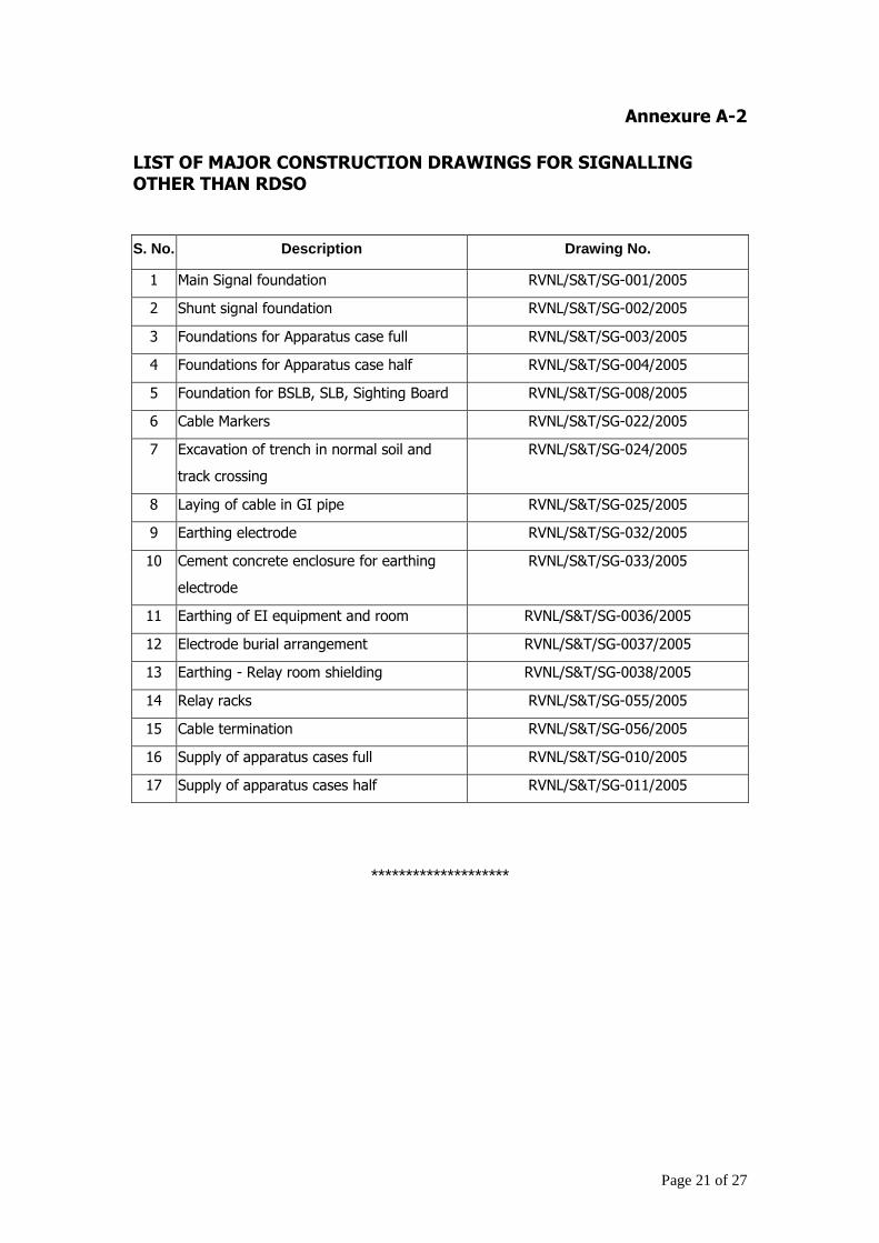


