

AFRL-PR-WP-TR-2003-2032
CARBON-PHENOLIC CAGES FOR HIGH-SPEED BEARINGS Part II - Bearing Evaluation with a Multiply- Alkylated Cyclopentane (MAC) Lubricant Nelson H. Forster and Jeffrey R. Brown Mechanical Systems Branch (AFRL/PRTM) Turbine Engine Division Propulsion Directorate Air Force Research Laboratory, Air Force Materiel Command Wright-Patterson Air Force Base, OH 45433-7251 David T. Gerardi Universal Energy Systems, Inc. (UES, Inc.) 4401 Dayton Xenia Road Dayton, OH 45432 JANUARY 2003 Interim Report for 01 January 2001 – 01 August 2002
PROPULSION DIRECTORATE AIR FORCE RESEARCH LABORATORY AIR FORCE MATERIEL COMMAND WRIGHT-PATTERSON AIR FORCE BASE, OH 45433-7251
Approved for public release; distribution is unlimited.

NOTICE
USING GOVERNMENT DRAWINGS, SPECIFICATIONS, OR OTHER DATA INCLUDED IN THISDOCUMENT FOR ANY PURPOSE OTHER THAN GOVERNMENT PROCUREMENT DOES NOT INANY WAY OBLIGATE THE U.S. GOVERNMENT. THE FACT THAT THE GOVERNMENTFORMULATED OR SUPPLIED THE DRAWINGS, SPECIFICATIONS, OR OTHER DATA DOESNOT LICENSE THE HOLDER OR ANY OTHER PERSON OR CORPORATION; OR CONVEY ANYRIGHTS OR PERMISSION TO MANUFACTURE, USE, OR SELL ANY PATENTED INVENTIONTHAT MAY RELATE TO THEM.
~
-7NELSON H. FORSTER, Ph.D. <===
Principal Mechanical EngineerMechanical Systems Branch
';;j~ ~,~THEODORE G. FECKEChief EngineerTurbine Engine DivisionPropulsion Directorate
Do not return copies of this report unless contractual obligations or notice on a specificdocument require its return.

i
REPORT DOCUMENTATION PAGE Form Approved OMB No. 0704-0188
The public reporting burden for this collection of information is estimated to average 1 hour per response, including the time for reviewing instructions, searching existing data sources, searching existing data sources, gathering and maintaining the data needed, and completing and reviewing the collection of information. Send comments regarding this burden estimate or any other aspect of this collection of information, including suggestions for reducing this burden, to Department of Defense, Washington Headquarters Services, Directorate for Information Operations and Reports (0704-0188), 1215 Jefferson Davis Highway, Suite 1204, Arlington, VA 22202-4302. Respondents should be aware that notwithstanding any other provision of law, no person shall be subject to any penalty for failing to comply with a collection of information if it does not display a currently valid OMB control number. PLEASE DO NOT RETURN YOUR FORM TO THE ABOVE ADDRESS.
1. REPORT DATE (DD-MM-YY) 2. REPORT TYPE 3. DATES COVERED (From - To)
January 2003 Interim 01/01/2001 – 08/01/2002 5a. CONTRACT NUMBER
In-house 5b. GRANT NUMBER
4. TITLE AND SUBTITLE
CARBON-PHENOLIC CAGES FOR HIGH-SPEED BEARINGS Part II - Bearing Evaluation with a Multiply-Alkylated Cyclopentane (MAC) Lubricant 5c. PROGRAM ELEMENT NUMBER
62203F 5d. PROJECT NUMBER
3048 5e. TASK NUMBER
06
6. AUTHOR(S)
Nelson H. Forster and Jeffrey R. Brown (AFRL/PRTM) David T. Gerardi (UES, Inc.)
5f. WORK UNIT NUMBER
IH 7. PERFORMING ORGANIZATION NAME(S) AND ADDRESS(ES) 8. PERFORMING ORGANIZATION
REPORT NUMBER
Mechanical Systems Branch (AFRL/PRTM) Turbine Engine Division Propulsion Directorate Air Force Research Laboratory, Air Force Materiel Command Wright-Patterson Air Force Base, OH 45433-7251
Universal Energy Systems, Inc. (UES, Inc.) 4401 Dayton Xenia Road Dayton, OH 45432
AFRL-PR-WP-TR-2003-2032
10. SPONSORING/MONITORING AGENCY ACRONYM(S)
AFRL/PRTM
9. SPONSORING/MONITORING AGENCY NAME(S) AND ADDRESS(ES)
Propulsion Directorate Air Force Research Laboratory Air Force Materiel Command Wright-Patterson Air Force Base, OH 45433-7251
11. SPONSORING/MONITORING AGENCY REPORT NUMBER(S)
AFRL-PR-WP-TR-2003-2032 12. DISTRIBUTION/AVAILABILITY STATEMENT
Approved for public release; distribution is unlimited. 13. SUPPLEMENTARY NOTES
Cleared for public release by the National Reconnaissance Office (NRO). See also Part I (AFRL-PR-WP-TR-2003-2031) and Part III (AFRL-PR-WP-TR-2003-2033).
14. ABSTRACT
This is the second part of a three-part series of reports to investigate carbon-phenolic bearing cages in high-speed, lightly lubricated bearings. This portion covers full-scale bearing testing with carbon-phenolic and cotton-phenolic cages impregnated with multi-ply, alkylated, cyclo pentane (MAC) lubricant, commercially known as Pennzane®. Experimentally, it was found that bearings fitted with the carbon-phenolic cages generate more heat than bearings fitted with the cotton-phenolic cage. This is the opposite of the intended result. The difference is attributed to damage of the steel raceway with carbon-phenolic cages. This occurred because of wear debris generated from the carbon fibers in the ball pocket. Additionally, the study provides a useful assessment of heat generation in lightly lubricated bearings with composite cages and the effect of thermal preloading on bearing heat generation.
15. SUBJECT TERMS
bearings, composite cages, control moment gyroscope
16. SECURITY CLASSIFICATION OF: 19a. NAME OF RESPONSIBLE PERSON (Monitor)
a. REPORT Unclassified
b. ABSTRACT Unclassified
c. THIS PAGE Unclassified
17. LIMITATION OF ABSTRACT:
SAR
18. NUMBER OF PAGES
32 Nelson H. Forster 19b. TELEPHONE NUMBER (Include Area Code)
(937) 255-4347
Standard Form 298 (Rev. 8-98) Prescribed by ANSI Std. Z39-18

iii
Table of Contents
Section Page List of Figures ....................................................................................................... iv List of Tables ........................................................................................................ v Acknowledgements ............................................................................................... vi 1. Introduction .................................................................................................... 1 2. Experimental ................................................................................................. 2 3. Results ........................................................................................................... 9 4. Discussion ..................................................................................................... 19 5. Conclusions .................................................................................................... 21 6. References .................................................................................................... 22

iv
List of Figures
Figure Page 1. Duplex Set of Test Bearings with Cotton-Phenolic Cages ................................. 3 2. Photograph of Test Bearings Mounted in the Test Rig ....................................... 7 3. Schematic of Test Bearing Support, Torque Measuring Instrumentation, and Test Shaft ...................................................................................................... 8 4. Plots for Bearing Outer Race Temperature during the Breakin with Clamped DF Bearings ......................................................................................................... 10 5. Plots for Bearing Outer Race Temperature on the Second day of Testing with the clamped DF bearings ............................................................................. 11 6. Plots for Bearing Outer Race Temperature for the Spring-Loaded Bearings on the First Day of Testing ................................................................................. 12 7. Outer Race Temperature and Friction Torque for the Cru 20 Bearings with the Pennzane Lubricant and Cotton-Phenolic Cages .............................................. 13 8. Outer Race Temperature and Friction Torque for the Cru 20 Bearings with the Pennzane Lubricant and Carbon-Phenolic Cages ........................................... 14 9. Comparison of Bearing Temperature with Carbon-Phenolic and Cotton- Phenolic Cages .................................................................................................... 14 10. Failure Modes of the Phenolic Cages: (a) Cotton-Phenolic Fails by Thermal Degradation of Matrix and Fibers, and (b) Carbon-Phenolic Fails by Thermal Degradation of the Matrix and Tearing of Carbon Fibers at 30,000 rpm .......... 15 11. Condition of a Bearing with a Carbon-Phenolic Cage after Testing at Shaft Speed of 20,000 rpm ......................................................................................... 16 12. Micrographs of the Bearing Surface of a Bearing Tested with a Carbon-Phenolic Cage .................................................................................................................... 17 13. Condition of a Bearing with a Cotton-Phenolic Cage after Testing at a Shaft Speed of 20,000 rpm ........................................................................................... 18 14. Micrographs of the Bearing Surface of a Bearing Tested with a Cotton- Phenolic Cage ..................................................................................................... 18

v
List of Tables Table Page 1. 206 Bearing Geometry .................................................................................... 2 2. Chronological List of Bearing Tests Performed ............................................... 3
vi
Acknowledgements This research was funded by the National Reconnaissance Office as Part of the Directors Innovation Initiative Program. Dr. Jeff Sanders of Air Force Research Laboratory Materials Directorate (AFRL/MLBT) was the program manager for the overall effort. The carbon-phenolic cages were fabricated under the direction of Mr. Wei Shih of Allcomp Inc., City of Industry, CA. The cages were vacuum impregnated with the Pennzane lubricant under the direction of Dr. Jeffrey Sanders of AFRL/MLBT. Mr. Garry Givan provided substantial test rig support in the evaluation of the bearings. Mr. Al Levelle, formerly of the Aerospace Corporation, provided very helpful discussion on the affects of preload in lightly lubricated duplex bearings. Dr. Lewis Rosado of AFRL/PRTM provided the micrographs of the bearing surfaces.

1
1. Introduction The objective of this effort was to develop a new bearing cage material made from a carbon fiber-phenolic resin matrix (carbon-phenolic), with the end goal of producing a material that would have better performance than cotton-phenolic cages in high-speed, lightly lubricated bearings. This is the second part of a three-part series of reports. This report addresses the experimental bearing evaluation. Part I addresses the initial material selection, mechanical and thermal characterization, and tribology testing, and Part III covers thermal modeling of the bearing. There is also a separate set of reports in progress from the Air Force Research Laboratory Materials Directorate that addresses testing in vacuum and hard coatings on the bearing steel. The rationale for selecting carbon-phenolic as a candidate material was based on the potential to significantly improve the mechanical and thermal properties of the cotton- phenolic material. Based on prior experience with carbon matrix - carbon fiber cages (C-C) [1-3], we anticipated that replacing cotton fibers with carbon fibers would greatly improve the thermal conductivity, strength, and modulus of elasticity, while also decreasing the coefficient of thermal expansion. Additionally, carbon-phenolic cages would be less expensive than C-C due to the cost associated with generating the matrix of the composite material. We also hoped to lower the coefficient of friction (COF) of the carbon-phenolic matrix by incorporating lubricants into the matrix of the cage. In Part I, we found that the mechanical and thermal properties were substantially better than cotton-phenolic, but the friction was approximately the same in both materials. We also found that there was not a substantial benefit with solid lubricants incorporated in the carbon-phenolic, but the Pennzane lubricant did provide a substantial benefit over dry carbon-phenolic, and dry cotton-phenolic. Based on the results from Part I, the bearing testing primarily examines the carbon-phenolic and cotton-phenolic with the Pennzane lubricant.

2
2. Experimental 2.1 Test Bearings Details of the bearing used in this study are given in Table 1. The bearings came as a DF duplex set with a nominal preload of 65 lb. The bearing manufacturer was the Barden Corporation, Danbury, Connecticut. The bearings came preassembled with cotton-phenolic cages. A photograph of a typical test bearing is shown in Figure 1. A total of 15 sets of bearings were tested. A chronological listing of the bearings tested is provided in Table 2. The first column in Table 2 provides a data set name that is referred to in other figures. Each box in the table represents a different set of bearings and each row a particular test on a given day. Eight sets of bearings tested were made from 52100 steel, four sets from M50 steel, one set from T15 steel that we previously had in the laboratory, and the last two bearings tested were made from Cru 20 steel. Eleven sets had silicon nitride rolling elements, while the others had metal balls of the same material as the race material. Additional details of the material combinations are given in Table 2. As shown in Table 2, most of the bearings were coated with the Pennzane lubricant. As part of this process the bearings were disassembled, reassembled with the carbon-phenolic cages, and the cages were vacuum impregnated with the lubricant while assembled in the bearing. The disassembly, assembly, coating, and vacuum impregnation was performed by AFRL/MLBT.
Table 1. 206 Bearing Geometry
Class 206, ABEC 7, single outer land guided cage Number of balls 11 Contact angle 15° Cage OD (in) 2.049 Outer race curvature factor 0.5175 Cage ID (in) 1.800 Inner race curvature factor 0.53 Cage land clearance (in) 0.011 Pitch diameter (in) 1.81 Cage pocket clearance (in) 0.016 Ball diameter (in) 0.375 Cage width (in) 0.590 Axial preload (lb) 65 Radial load (lb) 5

3
Figure 1. Duplex Set of Test Bearings with Cotton-phenolic Cages
NRO AFRL/PRTM In-House Testing Summary Test Dataset Comment Name Races Balls Cages Lubricant Speeds About Test H230 52100 52100 Cotton- Mil 7808 10 K New bearing phenolic squirt 110-minute break in H230a 52100 52100 Cotton- Mil 7808 10 K Nice steady state phenolic squirt (SS) response H230b 52100 52100 Cotton- Mil 7808 10 K Nice SS response phenolic squirt H231 52100 52100 Cotton- Mil 7808 20 K Ramped to 20K phenolic squirt failed after 15 min at 20K
H232 52100 52100 Cotton- Mil 7808 10 K 20 K
10K break in failed after 20 min at 20K
phenolic Squirt
Table 2 - Chronological List of Bearing Tests Performed

4
NRO
AFRL/PRTM
In-House Testing Summary
Test Dataset Comment Name Races Balls Cages Lubricant Speeds About Test H233a 52100 52100 Cotton- Pennzane 10 K Repeat of SS Phenolic coated H233b 52100 52100 Cotton- Pennzane 10 K Repeat of SS Phenolic coated
H233c 52100 52100 Cotton- Pennzane 20 K Failed after 44 min at 20K
Phenolic coated
H234 52100 Si3N4 Cotton- Pennzane 10 K New Bearing Phenolic coated Two steps at 178 & 227 min H234a 52100 Si3N4 Cotton- Pennzane 10 K Repeat of SS Phenolic coated H234b 52100 Si3N4 Cotton- Pennzane 10 K Repeat of SS Phenolic coated H234c 52100 Si3N4 Cotton- Pennzane 20 K Ramped to 20 K Phenolic coated Hi temp but no failure
H235 52100 Si3N4 Cotton- Pennzane 10 K New Bearing Phenolic coated H235a 52100 Si3N4 Cotton- Pennzane 10 K Repeat of SS Phenolic coated H235b 52100 Si3N4 Cotton- Pennzane 20 K Failed after Phenolic coated 26 min at 20K
H236 52100 Si3N4 Cotton- Durad 10 K New Bearing Phenolic coated Try a different lube H236a 52100 Si3N4 Cotton- Durad 10 K None Phenolic coated H236b 52100 Si3N4 Cotton- Durad 20 K Failed after Phenolic coated 7 min at 20K
Table 2 - Chronological List of Bearing Tests Performed (continued)

5
NRO
AFRL/PRTM
In-House Testing Summary
Test Dataset Comment Name Races Balls Cages Lubricant Speeds About Test
H237 52100 52100 Cotton- Phenolic
Pennzane coated 10 K New Bearing
H237a 52100 52100 Cotton- Pennzane 10 K Repeat of SS for 1 h
Phenolic coated Disassembled and inspected
H238 52100 Si3N4 Cotton- Phenolic
Pennzane coated 10 K
New Bearing Ran for 5 h
H239 M50 Si3N4 Cotton- Pennzane 10 K New Bearing First Spring Loaded Test
Phenolic coated
H239a M50 Si3N4 Cotton- Phenolic
Pennzane
coated 10 K
Removed Cover Plate – Ramped up to 20 K
H239b M50 Si3N4 Cotton-Phenolic
Pennzane
Coated 10 K 30 lb spring load Ramped to 20K
H239c M50 Si3N4 Cotton- Pennzane 20 K 60 lbs spring load Phenolic coated Ramped to 20K
H240 52100 52100 Cotton- Pennzane 10 K New Bearing Phenolic coated 60 lb spring load
H241 M50 Si3N4 Carbon- Pennzane 10 K New Bearing 60 lb Phenolic coated H241a M50 Si3N4 Carbon- Pennzane 10K 60 lb Phenolic coated Ramped to 20K rpm H241b M50 Si3N4 Carbon- Pennzane 10K 30 lb Phenolic coated Ramped to 20K rpm H241c M50 Si3N4 Carbon- Pennzane 20K 60 lb Phenolic coated Ramped to 20K rpm
H242 M50 Si3N4 Cotton- Pennzane 10K Cleaned & relubed Phenolic coated bearing from H241 H242a M50 Si3N4 Cotton- Pennzane 20K 60 lb load Phenolic coated Ramped to 35K rpm
Table 2 - Chronological List of Bearing Tests Performed (continued)

6
H243
M50 Si3N4 Carbon- Pennzane 10K Cleaned, relubed, new spring 60 lb
Phenolic coated NRO
AFRL/PRTM
In-House Testing Summary
Test Dataset Comment Name Races Balls Cages Lubricant Speeds About Test
H243a M50 Si3N4 Carbon- Pennzane 20K Ramped to 30K rpm Phenolic coated
H244 T15 Si3N4 Carbon- Pennzane 10K Different Brg Vendor & mat'l
Phenolic coated 60 lb H244a T15 Si3N4 Carbon- Pennzane 20K Ramped to 25 K rpm Phenolic coated
H245 CRU-20 Si3N4 Cotton- Pennzane 10K New brg mat'l Phenolic coated 60 lb H245a CRU-20 Si3N4 Cotton- Pennzane 20K Ramped to 28K rpm Phenolic coated
H246 CRU-20 Si3N4 Carbon- Pennzane 10K New brg Phenolic coated 60 lb H246a CRU-20 Si3N4 Carbon- Pennzane 20K Ramped to 28K rpm Phenolic coated
Table 2 – Chronological List of Bearing Tests Performed (concluded)

7
2.2 Experimental Test Rig A photograph of the test rig with the duplex bearings is shown in Figure 2. In operation, a 5-inch diameter housing connected to the back plate surrounds the bearing. A cover plate is bolted to the front of the housing. The housing and cover plate are not shown in Figure 2. In some of the higher speed tests, the cover plate was removed to improve the convective heat transfer by reducing the ambient air temperature. Tests with the cover plate removed are noted in Table 2. The test rig has been used in several studies to evaluate new concepts for cruise missile bearings [2,3] . In this effort, the rig was modified to accommodate the duplex bearings by making a new nose piece and outer race clamp to preload the bearings. In the second half of the testing, we modified the outer race clamp to use a spring to preload the bearings. The spring-loaded testing started with bearing H239 in Table 2. Most of the spring-loaded tests were run with a 60 lb spring preload, but some were run with a 30-lb spring preload. Whether the bearing test was 30 lb or 60 lb is noted in the comments in Table 2. Spring preloading was to done to ensure that the preload, on the bearings remains fairly constant regardless of thermal expansion factors. With the clamped DF bearings, the bearings rely solely on the bearing stiffness (i.e., modulus) to impose the bearing preload. A slight change in thermal gradient from the inner to outer race can have a dramatic effect on the bearing preload. The thermal effects on preload are covered in the Discussion Section and in more detail in the thermal analysis in Part III.
Figure 2. Photograph of Test Bearings Mounted in the Test Rig

8
A cross-section of the test rig is shown in Figure 3. The bearing torque was determined by the moment imposed to keep the outer race from rotating. The torque instrumentation is shown in Figure 3. Thermocouples were mounted on the outer and inner race in the locations shown in Figure 3. The bearing shaft is driven by an air turbine on the same shaft as the test bearings and approximately 18 inches away from the test bearings. This turbine gets fairly cool during operation, 10 to 0οC for 10,000 to 20,000 shaft rpm. This is due to the expansion of air to drive the shaft. This provides a heat sink for the inner race, which played a role in the thermal gradients that reduce the preload.
Figure 3. Schematic of Test Bearing Support, Torque Measuring Instrumentation, and Test Shaft

9
3. Results 3.1 Experimental Bearing Data During the early portion of this test program, it was found that the clamped DF bearings would experience a dramatic drop in bearing temperature and torque approximately 1 to 4 hours into the testing, as shown in Figure 4. Considerable effort was spent trying to resolve if this was due to lower friction or a change in bearing preload. By the end of the program, there was evidence that both were involved. Plots for several of the clamped DF bearings on the second day of testing are shown in Figure 5. On the second day, and subsequent days of testing, the bearings did not start with the high friction as seen in the first day. Instead, they generally approached the same steady state temperature from the day before. This indicates that the breakin of the bearings from the first day is a permanent change in friction, preload, or a combination of both. It was also found that at 10,000 rpm these bearing could be restarted on several days (up to 4 days was demonstrated) with no apparent change in bearing performance after the initial breakin period. Other parameters shown in Figure 4 and 5, include different ball material and lubricants. Of the lubricants tested, Mil-L-7808 turbine engine lubricant produced the lowest outer race bearing temperature. Pennzane and Durad 620 B were similar. The Mil-L-7808 lubricant has lower viscosity than either Pennzane or Durad 620B at these temperatures, so this is probably a viscosity effect. Also, bearings with ceramic rolling elements ran at lower outer race temperature than bearings with metal rolling elements. This is probably an impact on friction due to asperity contact in thin elastohydrodynamic (EHD) film conditions.

10
New bearing start-up; 10K RPM (outer race temperature); off-the-shelf Barden DF bearings; clamped outer races; 65 lb nominal pre-load
20
40
60
80
100
120
140
0 50 100 150 200 250 300 350
Time (min)
Tem
per
atu
re (
ºC)
Mil-7808, 52100 Balls
Pennzane, 52100 Balls
Pennzane, Si3N4 Balls
Durad, Si3N4 Balls
H233
H237
H232
H230H236
H235
H234
H238
* cotton-phenolic cages
Figure 4. Plots for Bearing Outer Race Temperature during the Breakin with
Clamped DF Bearings

11
Bearing start-up (following 1st day) withoff-the-shelf DF bearings - clamped outer races
10
15
20
25
30
35
40
45
50
55
60
0 50 100 150 200 250 300 350
Time (min)
Tem
per
atu
re (
ºC)
H230
H230
H233
H233
H234H235
H234
52100 Rolling Elements -Pennzane lubricant
Si3N4 Rolling Elements -Pennzane lubricant
Si3N4 Rolling Elements -Mil-7808 lubricant
Figure 5. Plots for Bearing Outer Race Temperature on the Second Day of Testing
with the Clamped DF Bearings

12
Several plots for the outer race temperature on the first day of testing with spring-loaded bearings are shown in Figure 6. There is still a decrease in bearing temperature with time, but the change is not as drastic as with the clamped bearings. The spring-loaded bearings are relatively insensitive to a change in loading from thermal gradients, so it is reasonable to attribute the decrease in bearing temperature in these tests to a decrease in bearing friction. Note that this decrease is not as drastic as what occurred with the clamped bearings. The decrease with clamped bearings appears to be compounded with a change in friction and preload. Figure 6 also shows bearings fitted with both cotton-phenolic and carbon-phenolic cages. In general, the cotton-phenolic cages are running about 20οC cooler than the carbon-phenolic cages. Ideally, it was intended that the carbon-phenolic would run slightly cooler than the cotton-phenolic cages.
New bearing start-up; 10K RPM (outer race temperature); hybrid bearings;spring mechanism installed to produce 65 lb pre-load; pennzane lubricated
20
40
60
80
100
120
140
0 50 100 150 200 250 300 350
Time (min)
Tem
per
atu
re (
ºC)
Cotton-phenolic cage, M50 races, 1st use of spring loading
M50 races, carbon-phenolic cage before and after re-lube (no flip) with new spring
Flipped cage;cotton-phenolic
Cotton-phenolic cage, CRU 20 races
BFG C-phenolic with loose cage clearance, T15 races
Cotton
Cotton
Cotton
Carbon
Carbon
Carbon
BFG C-phenolic with correct cage clearance; CRU 20 races
Carbon
H239
H245
H242
H246
H241
H244
H243
Figure 6. Plots for Bearing Outer Race Temperature for the Spring-Loaded Bearings on the First Day of Testing
13
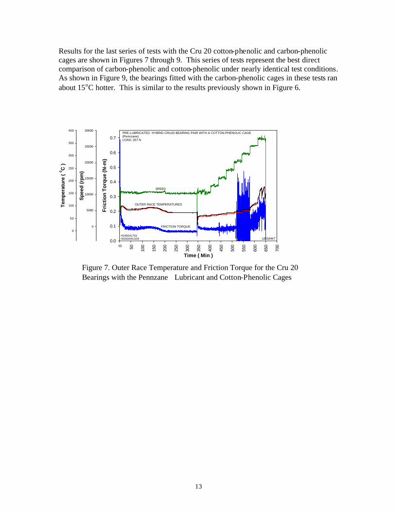
Results for the last series of tests with the Cru 20 cotton-phenolic and carbon-phenolic cages are shown in Figures 7 through 9. This series of tests represent the best direct comparison of carbon-phenolic and cotton-phenolic under nearly identical test conditions. As shown in Figure 9, the bearings fitted with the carbon-phenolic cages in these tests ran about 15οC hotter. This is similar to the results previously shown in Figure 6.
Time ( Min )
0 50 100
150
200
250
300
350
400
450
500
550
600
650
700
Fri
ctio
n T
orq
ue
(N-m
)
0.0
0.1
0.2
0.3
0.4
0.5
0.6
0.7
Spe
ed (
rpm
)
0
5000
10000
15000
20000
25000
30000
Tem
pera
ture
( 0 C
)
0
50
100
150
200
250
300
350
400
H245041702H020204U105 UES/HKT
SPEED
OUTER RACE TEMPERATURES
FRICTION TORQUE
PRE-LUBRICATED HYBRID CRU20 BEARING PAIR WITH A COTTON-PHENOLIC CAGE(Pennzane)LOAD: 267 N
Figure 7. Outer Race Temperature and Friction Torque for the Cru 20 Bearings with the Pennzane Lubricant and Cotton-Phenolic Cages

14
Time (Min)
0 50 100
150
200
250
300
350
400
450
500
550
600
650
Fri
ctio
n T
orq
ue
(N-m
)
0.0
0.1
0.2
0.3
0.4
0.5
0.6
0.7
Spe
ed (
rpm
)
0
5000
10000
15000
20000
25000
30000Te
mpe
ratu
re (
0 C )
0
50
100
150
200
250
300
350
400H246040232H020204U106
UES/HKT
SPEED
OUTER RACE TEMPERATURES
FRICTION TORQUE
PRE-LUBRICATED HYBRID CRU20 BEARING PAIR WITH A CARBON-GRAPHITE CAGE(Pennzane)LOAD: 267 N
Figure 8. Outer Race Temperature and Friction Torque for the Cru 20 Bearings with the Pennzane Lubricant and Carbon-Phenolic Cages
Outer race temperature -- H245a, H246awith spring-loaded, pennzane lubricant (cotton-phenolic and initial carbon-phenolic cage material)
0
25
50
75
100
125
150
175
200
0 40 80 120 160 200 240 280 320
Time (min)
Tem
per
atu
re (º
C) FRNT Outer
FRNT Outer
10K RPM 15K RPM 17.5K RPM 20K RPM12.5K RPM 27.5K RPM25K RPM22.5K RPM
Carbon-phenolic
Cotton-phenolic
Figure 9. Comparison of Bearing Temperature with Carbon-Phenolic and Cotton-Phenolic Cages

15
3.2 Examination of the Bearings after Testing
The condition of the cotton-phenolic cage and carbon-phenolic cages after tests H233c and H243a are shown in Figures 10 (a) and (b). The cotton-phenolic cage is a thermal failure. The material was severely thermally degraded and apparently lost mechanical strength, resulting in destruction of the ball pocket webs. This failure occurred at 20,000 rpm. The front cover was still being used on the test rig during this time period. The bearing outer race was at a temperature of about 160ο C when the bearing failed. The cage in Figure 10 (b) is from a test with the cover removed but at a speed of 30,000 rpm. The cage shown in the figure was spongy, indicating degradation of the matrix. The separation of the outer layer is tearing of the carbon fibers due to centrifugal stress. A C-C composite cage, reinforced with cross-stitching, is one way to eliminate this failure mode, if needed.
Figure 10. Failure Modes of the Phenolic Cages: (a) Cotton-Phenolic Fails by Thermal Degradation of Matrix and Fibers, and (b) Carbon-Phenolic Fails by Thermal Degradation of the Matrix and Tearing of Carbon Fibers at 30,000 rpm
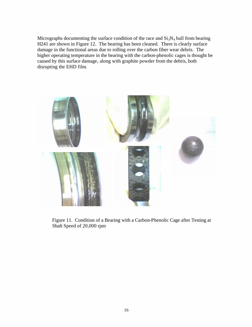
The condition of bearing H241 after test and prior to cleaning is shown in Figure 11. This bearing was Pennzane lubricated and tested to speeds of 20,000 rpm, 60 lb spring load, without failure. However, there is considerable black wear debris in the bearing. This debris came from wear in the ball pockets. The land surfaces of the bearing did not have high wear. Since this wear was not seen on the land, or in the high-speed friction tests, it appears that the wear of ball pockets is aggravated by the impact loading due to ball collisions in the pocket.
16
Micrographs documenting the surface condition of the race and Si3N4 ball from bearing H241 are shown in Figure 12. The bearing has been cleaned. There is clearly surface damage in the functional areas due to rolling over the carbon fiber wear debris. The higher operating temperature in the bearing with the carbon-phenolic cages is thought be caused by this surface damage, along with graphite powder from the debris, both disrupting the EHD film.
Figure 11. Condition of a Bearing with a Carbon-Phenolic Cage after Testing at Shaft Speed of 20,000 rpm

17
Figure 12. Micrographs of the Bearing Surface of a Bearing Tested with a Carbon-Phenolic Cage
The surface condition of bearing H239 after testing is shown in Figure 13. This bearing had a cotton-phenolic cage and tested to speeds of 20,000 rpm without failure. There is some polishing and slight oil degradation at the cage land surface; otherwise, this bearing is very clean and in very good shape. Micrographs documenting the surface condition of the race and Si3N4 ball from bearing 241 are shown in Figure 14. The active surfaces of the bearing are in very good shape.
Edge of inner race ball track (100x)
ball track
Si3N4 ball, outside wear groove (100x)
Si3N4 ball, inside wear groove (100x)

18
Figure 13. Condition of a Bearing with a Cotton-phenolic Cage after Testing at Shaft Speed of 20,000 rpm
Figure 14. Micrographs of the Bearing Surface of a Bearing Tested with a Cotton- Phenolic Cage
approx. edge of inner race ball track
Si3N4 ball (100x)

19
4. Discussion 206-size bearings can operate at 10,000 shaft rpm with only a light coating of lubricant, at a moderate load of 65 lb, in air environment. As the speed increased from 10,000 to 20,000 shaft rpm, thermal management became a concern. Failure was encountered at 20,000 rpm when the environment was totally contained by a surrounding structure. By opening up the front of that structure to ambient air, we were able to achieve bearing speeds as high as 30,000 rpm. The increase in speed is attributed to improved heat transfer via convection to the ambient air. In vacuum, this form of heat transfer is not available, so considerable attention would have to be given to thermal management via structural design, heat sinks, and thermal conductivity. The failure with the cover, or with the cover removed, was determined by bearing temperature. Essentially, when the bearing outer race temperature exceeded 160ο C, the bearings would fail. Failure was accompanied by dry surfaces (lack of lubricant) on the races and cage, and thermal/mechanical failure of the bearing cage. The cotton-phenolic cages experienced more distress than the carbon-phenolic cages in these failure scenarios. The performance of the bearings was affected by preload method, clamped bearings compared to spring loaded. The bearing inner race in this particular test rig runs cooler than usual because of the air turbine heat sink at the end of the shaft. With this type of gradient outer race running hotter than the inner race, the bearing unloaded during testing. This is part of the drop in the initial breakin with the clamped bearings shown in Figure 4. With the spring-loaded bearings, there is good confidence that the load remained fairly constant at 60 lb or 30 lb, depending on the test. However, there is still a drop in bearing operating temperature with spring-loaded bearings, but not as significant as with the clamped bearing. The drop with spring-loaded bearing is attributed to a change in friction during the breakin period. The change with the clamped bearings is a combination of friction and preload. There was a beneficial effect of Si3N4 rolling elements compared to steel rolling elements and Mil-L-7808 lubricant compared to the Pennzane, in terms of reducing bearing temperature. The benefit of Si3N4 over steel is credited to a reduction in friction due to an improvement in boundary lubrication. The benefit with Mil-L-7808 is attributed to lower friction as a result of lower viscosity. Even though Mil-L-7808 generates lower temperatures, its higher volatility may not be attractive for a vacuum environment.

20
Most importantly to this program, carbon-phenolic cages did not perform better than cotton-phenolic cages in terms of bearing temperature and bearing surface condition. The conditions of the bearing surface in Figure 12 are a significant problem for a bearing that is expected to have reliable life over several years with only minimal lubrication. The surface damage was caused by wear debris generated from the pocket and likely aggravated by impact forces from ball collisions. The increase in operating temperature is also probably related to this same surface degradation of the bearing steel. This would disrupt the EHD film and likely result in higher friction. The early carbon-phenolic cages were hand wrapped by Allcomp. Since that time, Allcomp has added a wrapping machine that uses uniform tension in the wrapping process. This will like reduce wear generation by producing a more uniform matrix with fewer voids. Another solution that AFRL/PRTM is pursuing is coating carbon-phenolic to enhance the wear resistance and lubricity. The early results with this approach look very promising.

21
5. Conclusions
In this effort, we examined carbon-phenolic as a potential replacement material for cotton-phenolic cages. In Part I, it was shown that the carbon-phenolic material has superior mechanical and thermal properties to cotton-phenolic. However, the bearings tested in Part II showed that the full-scale bearings encountered surface damage and higher operating temperatures than bearings fitted with cotton-phenolic cages. Both of these problems are attributed to wear debris released from the ball pockets during operation. There are potential ways to eliminate this wear debris. There are also substantial benefits to replacing a cotton-phenolic cage with a more advanced composite material cage. However, more research is required to find what that replacement material should be. If a carbon-phenolic material can be developed that does not generate wear debris, it will be superior to cotton-phenolic because of the material properties described in Part I.

22
6. References
1. Forster, N.H., Rosado, L., Shih, W.T., and Brown, J.R., “The Development of Carbon Carbon Composite Cages for Rolling Element Bearings,” Trib. Trans., 45, pp. 127 131 (2002). 2. Wagner, M.J., Forster, N.H., Van Treuren, K.W., and Gerardi, D.T., “Vapor Phase Lubrication for Expendable Gas Turbine Engines,” Journal of Engineering for Gas Turbines and Power, 122, pp. 185-190 (2000). 3. Forster, N.H., “High Temperature Lubrication of Rolling Contacts with Lubricants Delivered from the Vapor Phase and as Oil-Mists,” WL-TR-97-2003 (1997).


