Air Purger & Ammonia Purifier
by
Anand JoshiPartner Manik Engineers
Vice President AARPast President ISHRAE Pune
Member ASHRAE (USA), IIAR (USA), IETE, IGCC, IDA

Refrigerant Grade Anhydrous Ammonia Specifications-ANSI/IIAR 2
Purity Requirements• Ammonia Content 99.95%Min.• Non-Basic Gas in Vapor Phase 25PPM Max.• Non-Basic Gas in Liquid Phase 10 PPM Max.• Water 500 PPM Max.• Oil (as soluble in petroleum ether) 5 PPM Max.• Salt (calculated as NaCl) None• Pyridine, Hydrogen Sulfide, Naphthalene None
Increases electrical power demand
Decreases Refrigeration system capacity
Decreases system efficiency
Excess head pressure puts more strain on bearing and drive motors. Belt life is shortened and gasket seals are ruptured.
The presence of non-condensable gases

Increased pressure leads to increased temperature, which shortens the life of compressor valves and promotes the breakdown of lubricating oil.
Increases condenser scaling which increases maintenance cost and reduces life of condenser
Increase in discharge temperature leads to “Ammonia explosions” and it breaks down into Nitrogen and Hydrogen. Which means further addition to non-condensable gases.
The presence of non-condensable gases

Calculation of increased power cost
Plan Condition :Evaporation Pressure for -40°C, Condensing Pressure for 38°C, 13.7 kg/cm2
Refrigeration Capacity 500kWPower required by compressor 281kW*If our actual pressure is 0.5 Kg/cm2 higher i.e. 14.2 kg/cm2
Then power required would be 285kWThe 4 kW per hour for 6000 hours of operation is 24000kWIf Electricity Cost is Rs. 8/- per kWThe total increase in electricity bill is Rs. 1,92,000/-

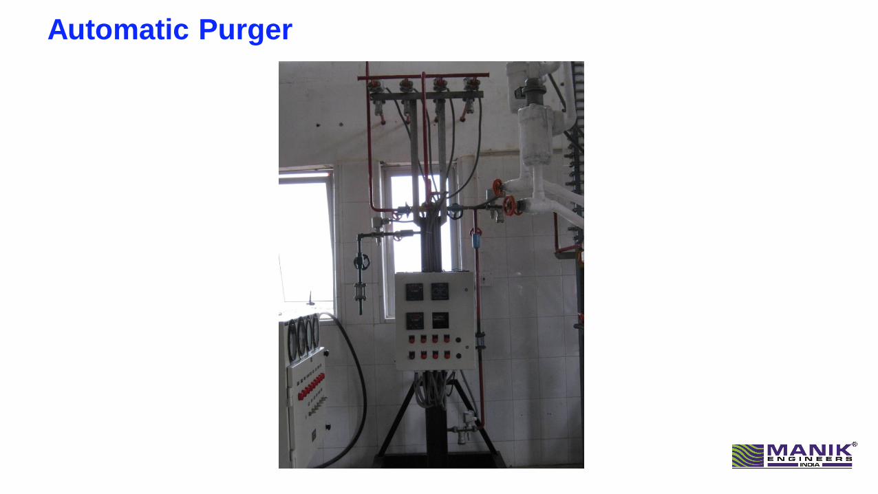
Automatic Purger
Fully automatic gas purger for refrigeration plants Maintains condensing temperature at nearly optimum operating conditions Reduces the concentration of non-condensable gases to a negligible Percentage No need separate refrigeration system
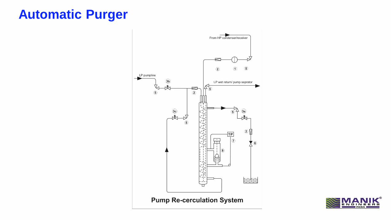
Automatic Purger
Where to Purge air ?
• Purge point connections must be at places where air will collect.
• Refrigerant gas enters a condenser at high velocity. By the time the gas reaches the far (and cool) end of the condenser, its velocity is practically zero.
• This is where the air accumulates and where the purge point connection should be made.
• Similarly, the purge point connection at the receiver should be made at a point furthest from the liquid inlet.
Purge Points
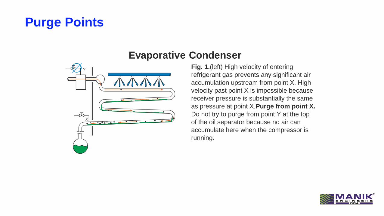
Fig. 1.(left) High velocity of entering
refrigerant gas prevents any significant air
accumulation upstream from point X. High
velocity past point X is impossible because
receiver pressure is substantially the same
as pressure at point X. Purge from point X.
Do not try to purge from point Y at the top
of the oil separator because no air can
accumulate here when the compressor is
running.
Evaporative Condenser
Purge Points
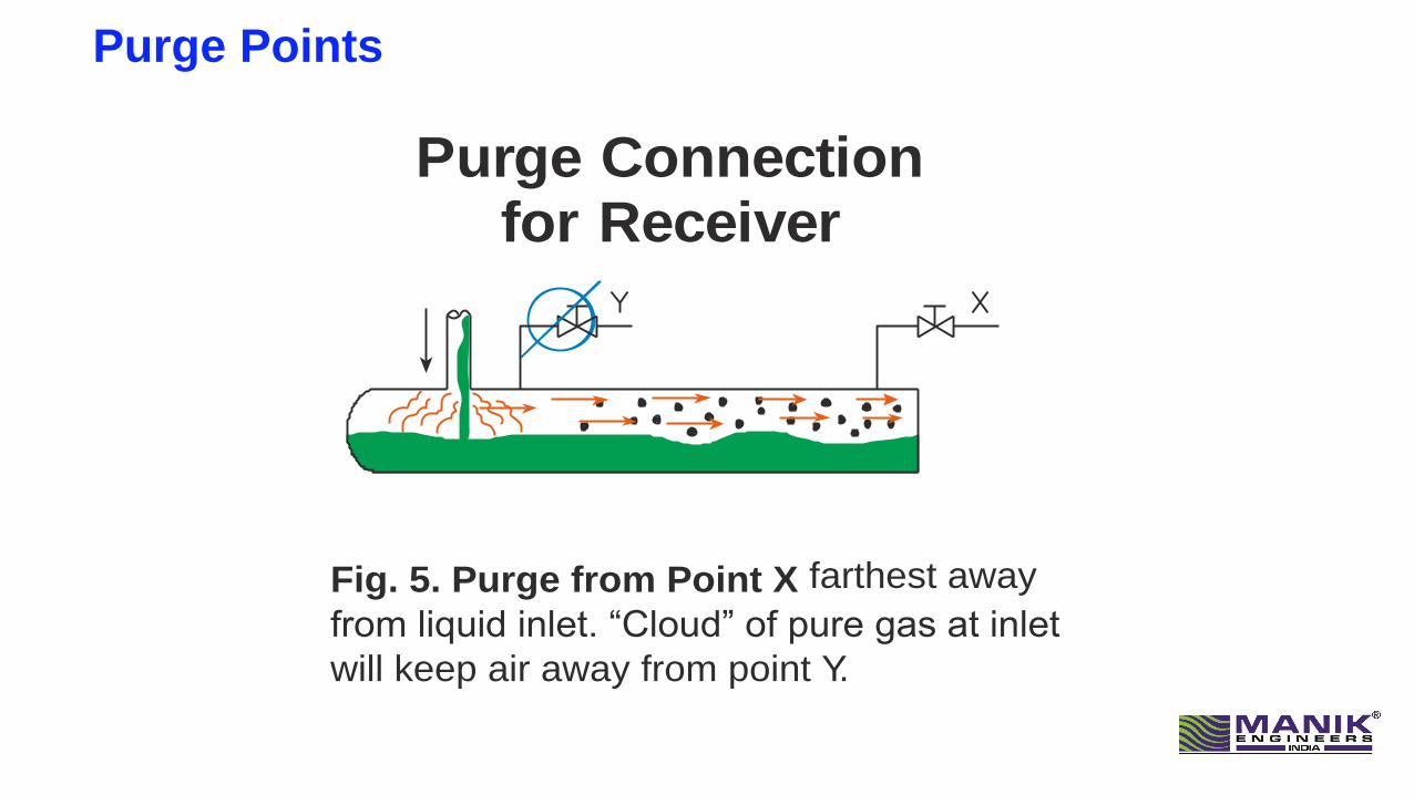
Purge Connection for Receiver
Fig. 5. Purge from Point X farthest away
from liquid inlet. “Cloud” of pure gas at inlet
will keep air away from point Y.

Installation of Air Purger
The gas purger can be placed where it is most appropriate. In most cases it is placed in the machinery room. No Need to Install above Condenser. Pipe Line Connection for Pump Re-circulation
1. Sky Blue: Low Temperature Liquid Line Inlet(A): Lowest Temperature point such as Ammonia Pump Outlet Header
2. Dark Blue(B): Wet suction return line: to be connected to low pressure accumulator
3. Yellow(C): From High temperature line such as condenser outlet, receiver
4. Green: Air vent connection to be immersed in water bucket
5. Red: Safety Relief valve: out let of the valve to be connected LP vessel
6. Black: Provided at the bottom of air purger for drain
Water Contamination and Removal inAmmonia Refrigeration Systems
Water Contamination is very Commonly observed due to Solubility of Ammonia in Water

Ammonia-water Relationship
• Ammonia and water have a great affinity for each other.
• For example, at atmospheric pressure and a temperature of 30°C., a saturated solution of ammonia and water will contain approximately 30 percent ammonia by weight. As the temperature of the solution is lowered, the ability to absorb ammonia increases.
• At 0° C. the wt. percentage increases to 46.5 percent;
• At -33°C. the percentage increases to 100 percent ammonia by wt.
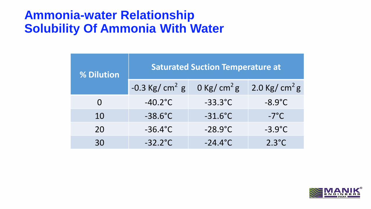
Ammonia-water RelationshipSolubility Of Ammonia With Water
% DilutionSaturated Suction Temperature at
-0.3 Kg/ cm2 g 0 Kg/ cm2 g 2.0 Kg/ cm2 g
0 -40.2°C -33.3°C -8.9°C
10 -38.6°C -31.6°C -7°C
20 -36.4°C -28.9°C -3.9°C
30 -32.2°C -24.4°C 2.3°C

Effects Of Water Contamination
• Water contamination lowers system efficiency
• Increases the electrical costs
• In addition, water also causes corrosion in the refrigerant cycle and
• accelerates the aging process in oil
• Increased wear and more frequent oil changes generate lower plant availability and increase service costs.
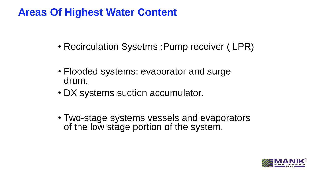
Areas Of Highest Water Content
• Recirculation Sysetms :Pump receiver ( LPR)
• Flooded systems: evaporator and surge drum.
• DX systems suction accumulator.
• Two-stage systems vessels and evaporators of the low stage portion of the system.
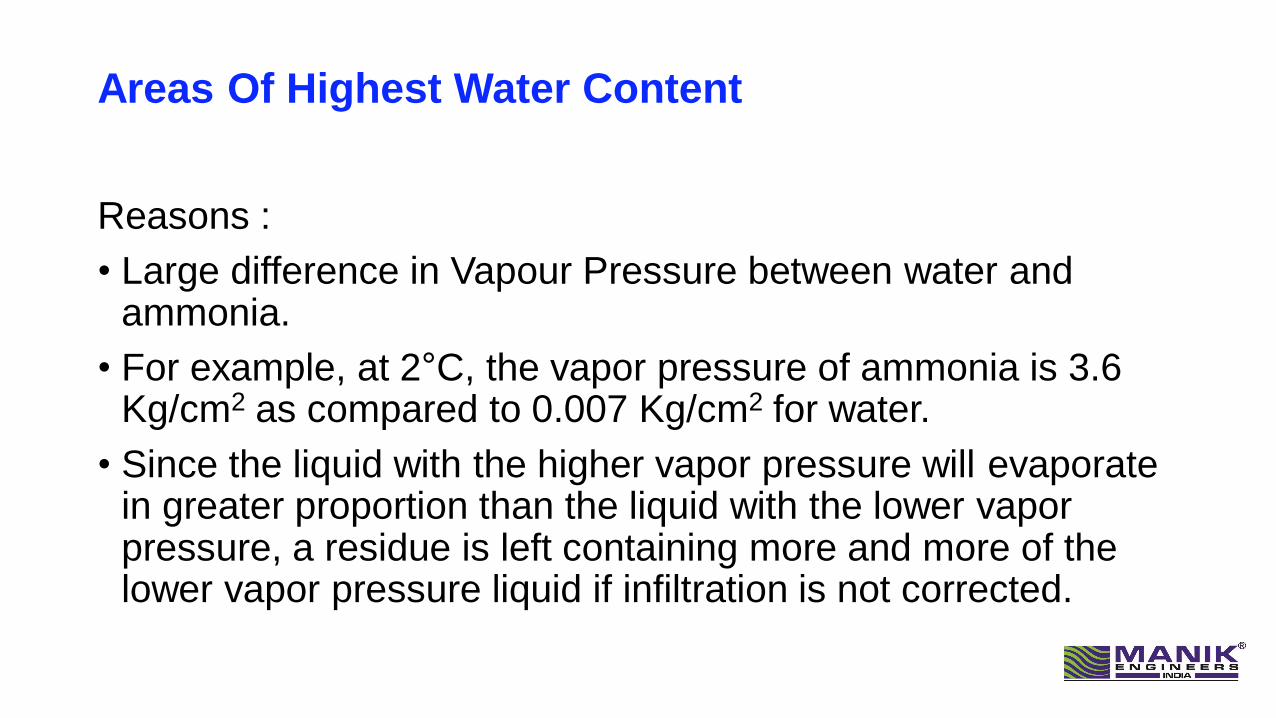
Areas Of Highest Water Content
Reasons :
• Large difference in Vapour Pressure between water and ammonia.
• For example, at 2°C, the vapor pressure of ammonia is 3.6 Kg/cm2 as compared to 0.007 Kg/cm2 for water.
• Since the liquid with the higher vapor pressure will evaporate in greater proportion than the liquid with the lower vapor pressure, a residue is left containing more and more of the lower vapor pressure liquid if infiltration is not corrected.
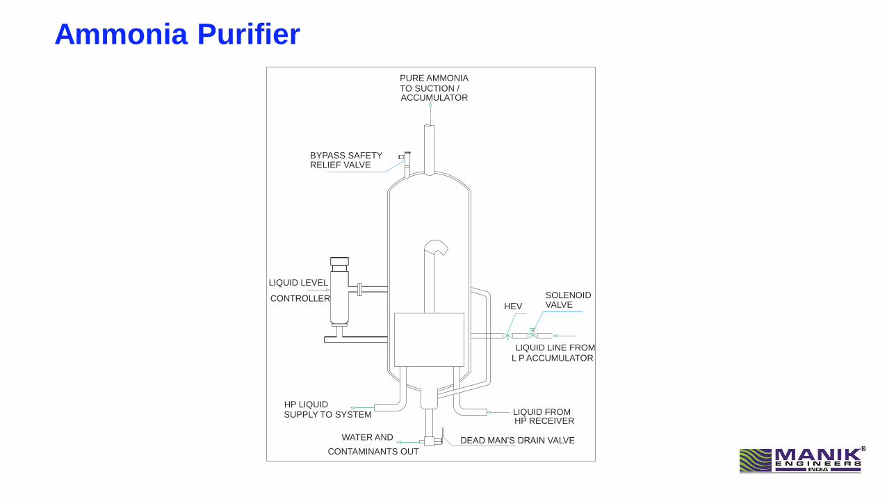
Ammonia Purifier
HEV
SOLENOID VALVE
LIQUID LEVEL
LIQUID FROM HP LIQUID
WATER AND
CONTAMINANTS OUT
LIQUID LINE FROM
PURE AMMONIATO SUCTION / ACCUMULATOR
CONTROLLER
SUPPLY TO SYSTEMHP RECEIVER
L P ACCUMULATOR
S
BYPASS SAFETY RELIEF VALVE
DEAD MAN’S DRAIN VALVE

Ammonia Purifier

Ammonia Purifier

Thank You