
Aircraft Flying QualitiesRobert Stengel, Aircraft Flight Dynamics
MAE 331, 2008
Copyright 2008 by Robert Stengel. All rights reserved. For educational use only.http://www.princeton.edu/~stengel/MAE331.html
http://www.princeton.edu/~stengel/FlightDynamics.html
• Flight test instrumentation
• Flying qualities requirements
• Flying qualities specifications
• Pilot opinion ratings
• CAP, C*, and other longitudinal criteria
• Pilot-induced oscillations
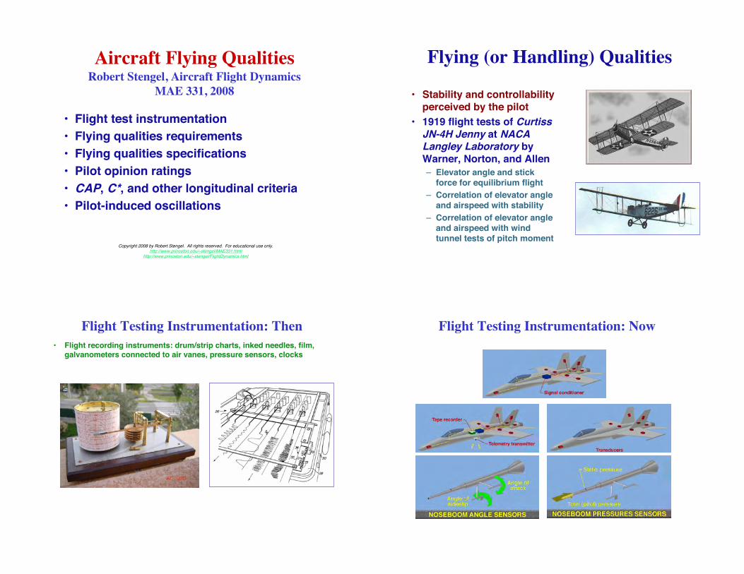
Flying (or Handling) Qualities
• Stability and controllabilityperceived by the pilot
• 1919 flight tests of CurtissJN-4H Jenny at NACALangley Laboratory byWarner, Norton, and Allen
– Elevator angle and stickforce for equilibrium flight
– Correlation of elevator angleand airspeed with stability
– Correlation of elevator angleand airspeed with windtunnel tests of pitch moment
Flight Testing Instrumentation: Then
• Flight recording instruments: drum/strip charts, inked needles, film,galvanometers connected to air vanes, pressure sensors, clocks
Flight Testing Instrumentation: Now

Nose Boom and Calibration Quadrants First Flying Qualities
Specification• First flying qualities specification: 1935, Edward Warner for
Douglas DC-4 transport
– Interviews with pilots and engineers
Flying Qualities Research at NACA
• Hartley Soulé and Floyd Thompson(late 1930s)
– Long- and short-period motions
– Time to reach specified bank angle
– Period and damping of oscillations
– Correlation with pilot opinion
• Robert Gilruth (1941-3)
– Parametric regions and boundaries
– Multi-aircraft criteria
– Control deflection, stick force, and
normal load factor
– Roll helix angle
– Lateral control power
Modern Flight Research and Development
• Application of control theory
• Variable-stability research aircraft, e.g., TIFS, AFTI F-16, NT-33A, andVRA
• The Princeton Connection [Flight Research Laboratory]
USAF/Calspan TIFSUSAF AFTI F-16
Princeton VRAUSAF/Calspan NT-33A
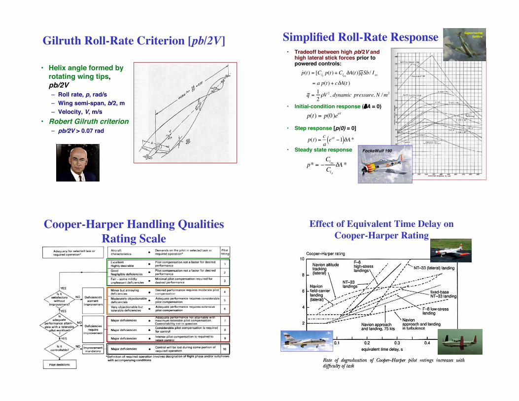
Gilruth Roll-Rate Criterion [pb/2V]
• Helix angle formed byrotating wing tips,pb/2V
– Roll rate, p, rad/s
– Wing semi-span, b/2, m
– Velocity, V, m/s
• Robert Gilruth criterion
– pb/2V > 0.07 rad
Simplified Roll-Rate Response• Tradeoff between high pb/2V and
high lateral stick forces prior topowered controls:
• Initial-condition response (!A = 0)
• Step response [p(0) = 0]
• Steady state response
p(t) = p(0)eat
˙ p (t) = [Clpp(t) + Cl!A
!A(t)]q Sb/ Ixx
= a p(t) + c!A(t )
q =1
2"V 2, dynamic pressure, N / m2
!
p(t) =c
aeat"1( )#A*
p* = !Cl"A
Cl p"A *
FockeWulf 190
SupermarineSpitfire
Cooper-Harper Handling Qualities
Rating Scale
Effect of Equivalent Time Delay on
Cooper-Harper Rating
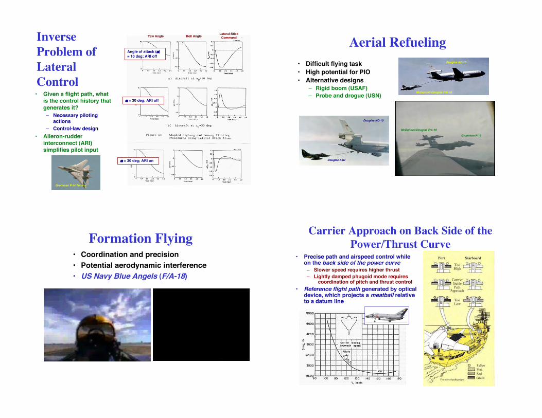
Inverse
Problem of
Lateral
Control• Given a flight path, what
is the control history that
generates it?
– Necessary pilotingactions
– Control-law design
• Aileron-rudderinterconnect (ARI)simplifies pilot input
Grumman F-14 Tomcat
Yaw Angle Roll AngleLateral-Stick
Command
Angle of attack (")
= 10 deg; ARI off
" = 30 deg; ARI off
" = 30 deg; ARI on
Aerial Refueling
• Difficult flying task
• High potential for PIO
• Alternative designs
– Rigid boom (USAF)
– Probe and drogue (USN)McDonnell-Douglas F/A-18
Douglas KC-10
Douglas KC-10
Douglas A4D
Grumman F-14
McDonnell-Douglas F/A-18
Formation Flying• Coordination and precision
• Potential aerodynamic interference
• US Navy Blue Angels (F/A-18)
Carrier Approach on Back Side of the
Power/Thrust Curve• Precise path and airspeed control while
on the back side of the power curve– Slower speed requires higher thrust
– Lightly damped phugoid mode requirescoordination of pitch and thrust control
• Reference flight path generated by opticaldevice, which projects a meatball relativeto a datum line
Military Flying Qualities
Specifications, MIL-F-8785C
• Specificationsestablished duringWWII
• US Air Force and Navycoordinated effortsbeginning in 1945
• First version appearedin 1948, last in 1980
• Distinctions by flightphase, mission, andaircraft type
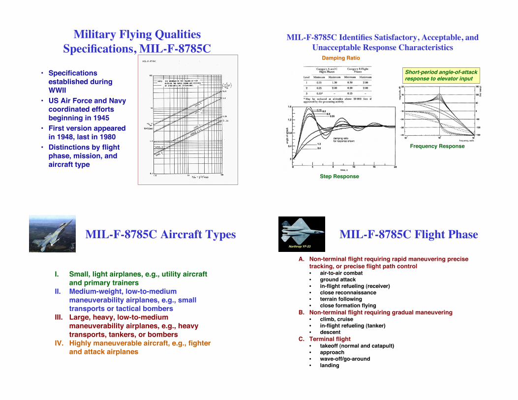
MIL-F-8785C Identifies Satisfactory, Acceptable, and
Unacceptable Response Characteristics
Damping Ratio
Step Response
Frequency Response
Short-period angle-of-attackresponse to elevator input
MIL-F-8785C Aircraft Types
I. Small, light airplanes, e.g., utility aircraftand primary trainers
II. Medium-weight, low-to-mediummaneuverability airplanes, e.g., smalltransports or tactical bombers
III. Large, heavy, low-to-mediummaneuverability airplanes, e.g., heavytransports, tankers, or bombers
IV. Highly maneuverable aircraft, e.g., fighterand attack airplanes
MIL-F-8785C Flight Phase
A. Non-terminal flight requiring rapid maneuvering precisetracking, or precise flight path control• air-to-air combat• ground attack
• in-flight refueling (receiver)• close reconnaissance• terrain following• close formation flying
B. Non-terminal flight requiring gradual maneuvering• climb, cruise• in-flight refueling (tanker)• descent
C. Terminal flight• takeoff (normal and catapult)• approach
• wave-off/go-around• landing
Northrop YF-23
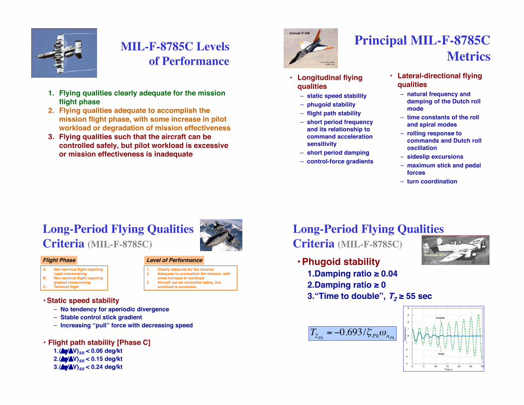
MIL-F-8785C Levels
of Performance
1. Flying qualities clearly adequate for the missionflight phase
2. Flying qualities adequate to accomplish themission flight phase, with some increase in pilotworkload or degradation of mission effectiveness
3. Flying qualities such that the aircraft can becontrolled safely, but pilot workload is excessiveor mission effectiveness is inadequate
Principal MIL-F-8785C
Metrics
• Longitudinal flyingqualities
– static speed stability
– phugoid stability
– flight path stability
– short period frequencyand its relationship tocommand accelerationsensitivity
– short period damping
– control-force gradients
• Lateral-directional flyingqualities
– natural frequency anddamping of the Dutch rollmode
– time constants of the rolland spiral modes
– rolling response tocommands and Dutch rolloscillation
– sideslip excursions
– maximum stick and pedalforces
– turn coordination
Convair F-106
Long-Period Flying Qualities
Criteria (MIL-F-8785C)
• Static speed stability– No tendency for aperiodic divergence
– Stable control stick gradient
– Increasing “pull” force with decreasing speed
A. Non-terminal flight requiringrapid maneuvering
B. Non-terminal flight requiringgradual maneuvering
C. Terminal flight
1. Clearly adequate for the mission2. Adequate to accomplish the mission, with
some increase in workload3. Aircraft can be controlled safely, but
workload is excessive
Level of PerformanceFlight Phase
• Flight path stability [Phase C]1.(!"/!V)SS < 0.06 deg/kt
2.(!"/!V)SS < 0.15 deg/kt
3.(!"/!V)SS < 0.24 deg/kt
Long-Period Flying Qualities
Criteria (MIL-F-8785C)
• Phugoid stability1.Damping ratio ! 0.04
2.Damping ratio ! 0
3.“Time to double”, T2 ! 55 sec
!
T2Ph
= "0.693/#Ph$
nPh
Grumman XF5F
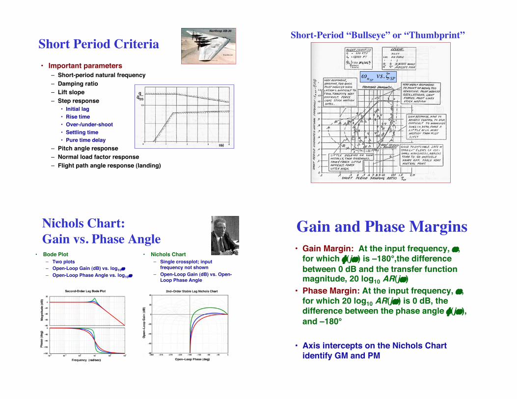
Short Period Criteria
• Important parameters
– Short-period natural frequency
– Damping ratio
– Lift slope
– Step response
• Initial lag
• Rise time
• Over-/under-shoot
• Settling time
• Pure time delay
– Pitch angle response
– Normal load factor response
– Flight path angle response (landing)
Northrop XB-35
Short-Period “Bullseye” or “Thumbprint”
!
"nSP
vs.#SP
Nichols Chart:
Gain vs. Phase Angle• Bode Plot
– Two plots
– Open-Loop Gain (dB) vs. log10#
– Open-Loop Phase Angle vs. log10#
• Nichols Chart
– Single crossplot; inputfrequency not shown
– Open-Loop Gain (dB) vs. Open-Loop Phase Angle
Gain and Phase Margins
• Gain Margin: At the input frequency, #,for which $(j#) is –180°,the difference
between 0 dB and the transfer functionmagnitude, 20 log10 AR(j#)
• Phase Margin: At the input frequency, #,for which 20 log10 AR(j#) is 0 dB, thedifference between the phase angle $(j#),
and –180°
• Axis intercepts on the Nichols Chartidentify GM and PM
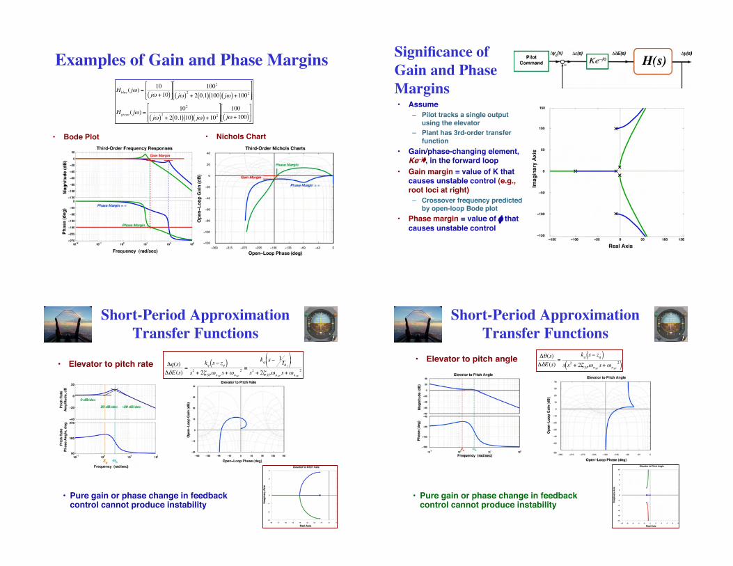
Examples of Gain and Phase Margins
• Bode Plot • Nichols Chart!
Hblue ( j") =10
j" +10( )
#
$ %
&
' (
1002
j"( )2
+ 2 0.1( ) 100( ) j"( ) +1002
#
$ % %
&
' ( (
Hgreen ( j") =10
2
j"( )2
+ 2 0.1( ) 10( ) j"( ) +102
#
$ % %
&
' ( (
100
j" +100( )
#
$ %
&
' (
Significance of
Gain and Phase
Margins• Assume
– Pilot tracks a single outputusing the elevator
– Plant has 3rd-order transferfunction
• Gain/phase-changing element,Ke–j$, in the forward loop
• Gain margin = value of K thatcauses unstable control (e.g.,root loci at right)
– Crossover frequency predictedby open-loop Bode plot
• Phase margin = value of $ that
causes unstable control
Short-Period Approximation
Transfer Functions
• Elevator to pitch rate
!
"q(s)
"#E(s)=
kq s$ zq( )s2 + 2% SP&nSP
s+&nSP
2'
kq s$ 1T( 2
)
* +
,
- .
s2 + 2% SP&nSP
s+&nSP
2
• Pure gain or phase change in feedbackcontrol cannot produce instability
Short-Period Approximation
Transfer Functions
• Elevator to pitch angle
!
"#(s)
"$E(s)=
kq s% zq( )s s
2 + 2& SP'nSPs+'nSP
2( )
• Pure gain or phase change in feedbackcontrol cannot produce instability
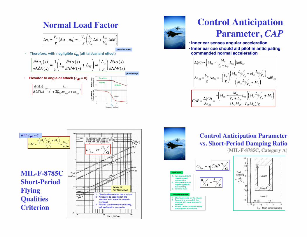
Normal Load Factor
• Therefore, with negligible L!E (aft tail/canard effect)
!
"nz =VN
g" ˙ # $"q( ) = $
VN
g
L#
VN
"# +L%E
VN
"%E&
' (
)
* +
!
"#nz (s)
"#$E(s)=1
gL%
"#%(s)
"#$E(s)+ L$E
&
' (
)
* + ,
L%
g
&
' (
)
* + "#%(s)
"#$E(s)
positive down
positive up
!
"#(s)
"$E(s)%
k#
s2
+ 2&SP'
nSPs+'
nSP
2
• Elevator to angle of attack (L!E = 0)
Control Anticipation
Parameter, CAP• Inner ear senses angular acceleration
• Inner ear cue should aid pilot in anticipatingcommanded normal acceleration
!
" ˙ q (0) = M#E $M%
VN + L%
L#E
&
' (
)
* + "#ESS
"nSS =VN
g"qSS = $
VN
g
&
' (
)
* +
M#E
L%VN
$ M%L#E
VN
& ' (
) * +
Mq
L%VN
+ M%
& ' (
) * +
"#ESS
!
CAP =" ˙ q (0)
"nSS
=
# M$E #M%
VN + L%
L$E
&
' (
)
* + Mq
L%VN
+ M%
& ' (
) * +
L%M$E # L$E M%( ) g
MIL-F-8785C
Short-Period
Flying
Qualities
Criterion
!
CAP =
" Mq
L#VN
+ M#
$ % &
' ( )
L# g*+nSP
2
nz /#
!
"nSPvs.
nz
#
1. Clearly adequate for the mission2. Adequate to accomplish the
mission, with some increase inworkload
3. Aircraft can be controlled safely,but workload is excessive
Level ofPerformance
with L!E = 0 Control Anticipation Parameter
vs. Short-Period Damping Ratio(MIL-F-8785C, Category A)
A. Non-terminal flightrequiring rapidmaneuvering
B. Non-terminal flightrequiring gradualmaneuvering
C. Terminal flight
1. Clearly adequate for the mission2. Adequate to accomplish the
mission, with some increase inworkload
3. Aircraft can be controlled safely,but workload is excessive
Level of Performance
Flight Phase
!
"nSP
= CAPnz
#
!
nz"#L"g
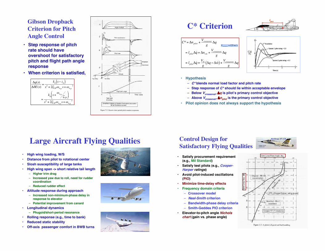
Gibson Dropback
Criterion for Pitch
Angle Control
• Step response of pitchrate should haveovershoot for satisfactorypitch and flight path angleresponse
• When criterion is satisfied,
!
"q(s)
"#E(s)=
kq s$ zq( )s2 + 2% SP&nSP
s+&nSP
2
=
kq s+&nSP
% SP
'
( )
*
+ ,
s2 + 2% SP&nSP
s+&nSP
2
C* Criterion
• Hypothesis
– C* blends normal load factor and pitch rate
– Step response of C* should lie within acceptable envelope
– Below Vcrossover, !q is pilot"s primary control objective
– Above Vcrossover, !npilot is the primary control objective
• Pilot opinion does not always support the hypothesis
!
C* = "npilot +Vcrossover
g"q
= lpilot" ˙ q + "ncm +Vcrossover
g"q
= lpilot" ˙ q +VN
g"q #" ˙ $ ( ) +
Vcrossover
g"q
!
Vcrossover
"125 m /s
Large Aircraft Flying Qualities
• High wing loading, W/S
• Distance from pilot to rotational center
• Slosh susceptibility of large tanks
• High wing span -> short relative tail length
– Higher trim drag
– Increased yaw due to roll, need for ruddercoordination
– Reduced rudder effect
• Altitude response during approach
– Increased non-minimum-phase delay inresponse to elevator
– Potential improvement from canard
• Longitudinal dynamics
– Phugoid/short-period resonance
• Rolling response (e.g., time to bank)
• Reduced static stability
• Off-axis passenger comfort in BWB turns
Control Design for
Satisfactory Flying Qualities
• Satisfy procurement requirement(e.g., Mil Standard)
• Satisfy test pilots (e.g., Cooper-Harper ratings)
• Avoid pilot-induced oscillations(PIO)
• Minimize time-delay effects
• Frequency domain criteria
– Crossover model
– Neal-Smith criterion
– Bandwidth-phase delay criteria
– Smith-Geddes PIO criterion
• Elevator-to-pitch angle Nicholschart (gain vs. phase angle)
Northrop YF-17A
Pilot-Induced Oscillations
• MIL-F-8785C specifies no tendency for pilot-inducedoscillations (PIO)
– Uncommanded aircraft is stable but piloting actions couplewith aircraft dynamics to produce instability
Pilot-Induced Oscillations
• Category I: Linear pilot-vehicle system oscillations
• Category II: Quasilinear events with nonlinear contributions
• Category III: Nonlinear oscillations with transients
Hodgkinson, Neal, Smith, Geddes, Gibson et al
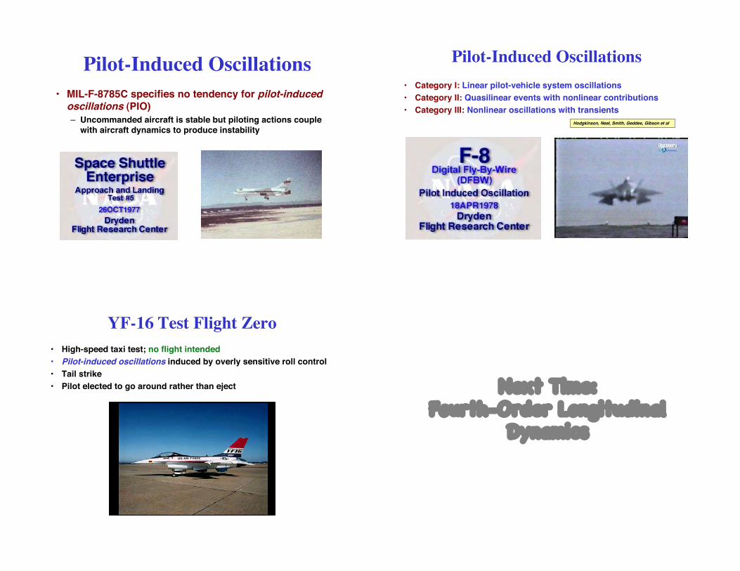
YF-16 Test Flight Zero
• High-speed taxi test; no flight intended
• Pilot-induced oscillations induced by overly sensitive roll control
• Tail strike
• Pilot elected to go around rather than eject Next Time:Fourth-Order Longitudinal
Dynamics


