


Aircraft Scatter
● Is using aircraft to redirect or “scatter” RF that would otherwise be lost in space
● Increases Communications Distance● Has increasing advantage over troposcatter as
frequency increases● Has increasing advantage as distance
increases, up to ~ 900 km (560 miles)● Truly a weak-signal mode

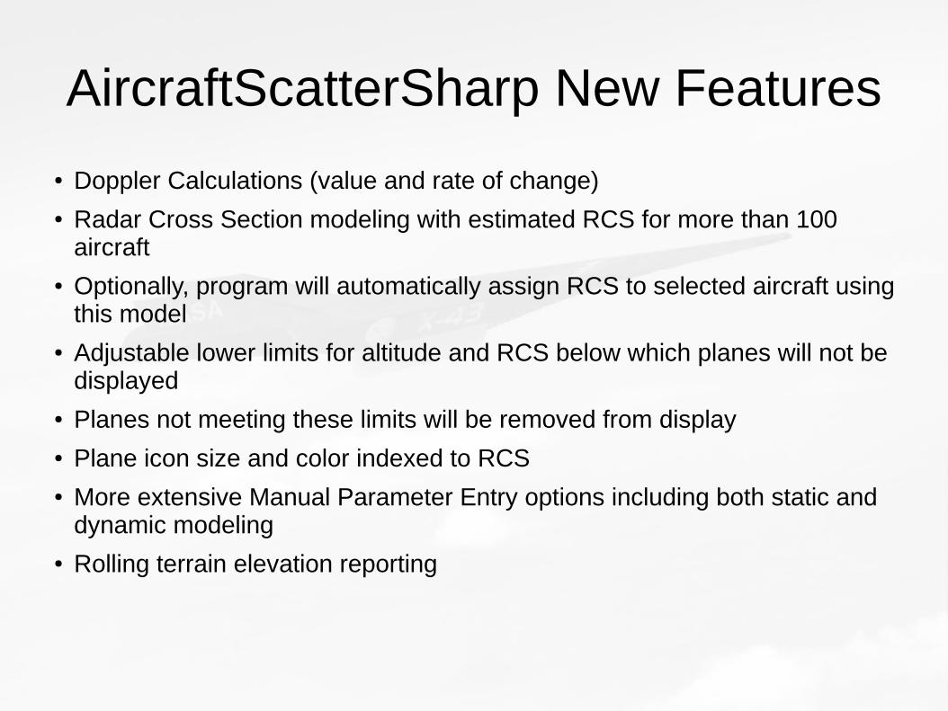
AircraftScatterSharp New Features
● Doppler Calculations (value and rate of change)● Radar Cross Section modeling with estimated RCS for more than 100
aircraft● Optionally, program will automatically assign RCS to selected aircraft using
this model● Adjustable lower limits for altitude and RCS below which planes will not be
displayed● Planes not meeting these limits will be removed from display● Plane icon size and color indexed to RCS● More extensive Manual Parameter Entry options including both static and
dynamic modeling● Rolling terrain elevation reporting

Aircraft Scatter is Bistatic Radar

Bistatic Radar
Bistatic Radar Equation for Path Loss (dB):
L = 10 log((lambda**2)*S/(((Rt**2)*(Rr)**2))) – 153
L = total loss (dB)
Rt = distance from transmitter to reflector (km)
Rr = distance from receiver to reflector (km)
Lambda = wavelength (m)
S = radar cross section of aircraft (sq m)● For lambda = 2M and Rt = Rr = 450km and S = 63 (B747):
AS Path Loss = - 235 dB
Free Space -135; Troposcatter -241; EME -252 dB

• F-117 fighter 0.1• B-2 bomber 0.01
Radar Cross Sections
Radar Cross Section meters2
B-1 bomber 0.01
“Advanced tactical fighter” 0.000001
Small single engine aircraft 1 *
Small fighter or 4-passenger jet (LearJet) 2 * #
Douglas DC-9 8 #
Boeing 707 16 #
Medium bomber or medium jet airliner 20 *
Large bomber or large jet airliner 40 *
Boeing 747 63 #
Jumbo jet 100*
Bird 0.01
Man 1
Automobile 100
* Skolnik # ARRL UHF/Microwave Experime nter’s Manual
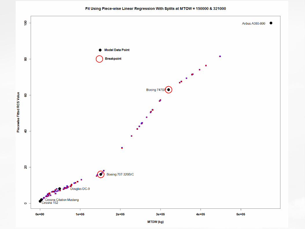

Estimated Radar Cross Sections
● A380 100
● B747-8 82
● B747-400 74
● A340-600 72
● B777-VIP 67
● B777-300 57
● A350-1000 52
● A340-300 51
● A340-200 50
● B787-10 45
● B787-9 44
● B777-200 43
● A330-200 41
● B787-8 37
● B767-400 31
● B767-300 18
● B767-200 16
● A321 12
● B737-900 11
● B737-100 7


Bistatic Radar
● Signal Loss is proportional to:– Log((Frequency)2) = 20 (Log(Frequency)) dB
– Log((Distance)4) = 40 Log(Distance) dB
● Signal Loss is inversely proportional to:– Log(Radar Cross Section) = 10 Log(RCS) dB

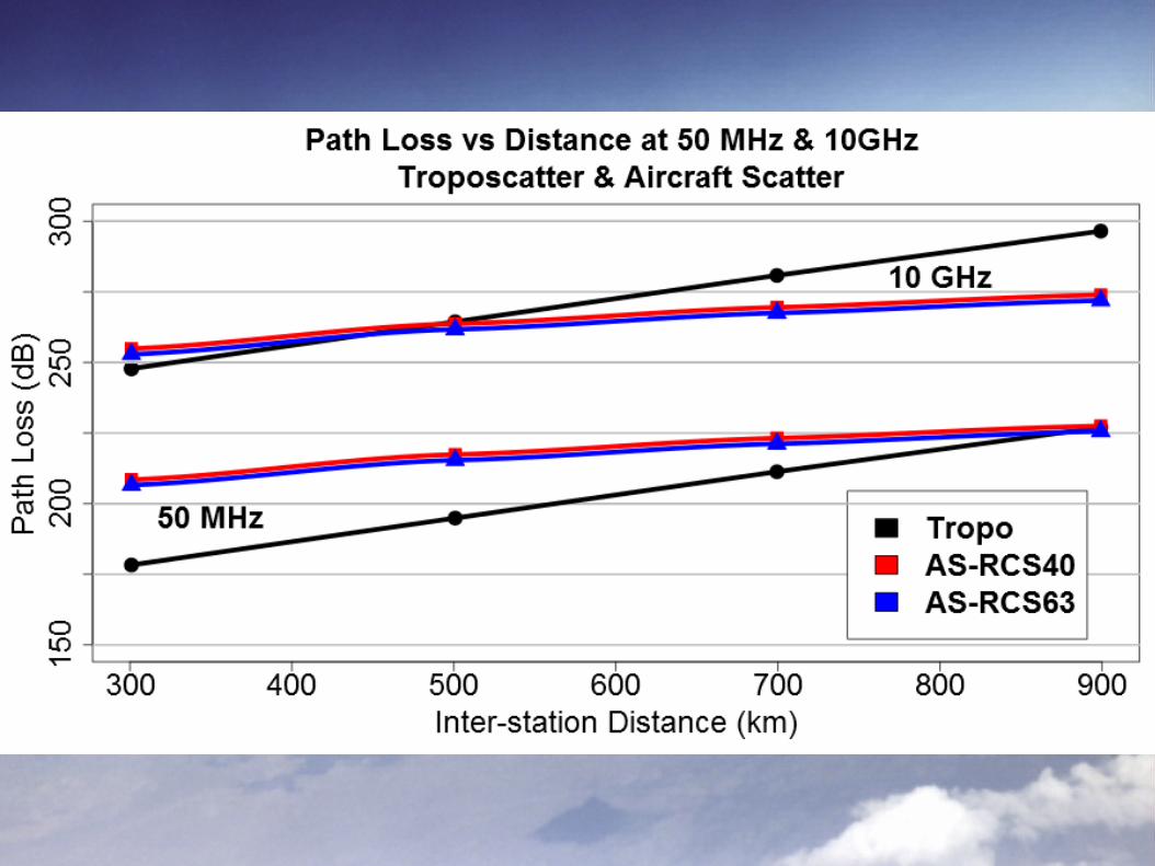
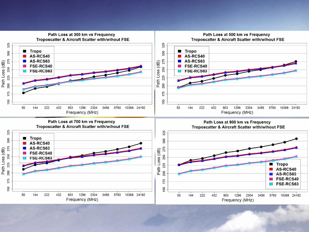
Aircraft Scatter’s Competition
● Troposcatter– Frequency dependence
of loss (dB) 30 log(Frequency)
– Distance dependence of loss ~9 dB / 100km
● Meteor Scatter– Loss (dB) proportional
to 30 Log(Frequency)–
– Best at distances of 800-2000 km
Aircraft scatter loss in dB is proportional to: 20 Log(Frequency) and 40 Log(Distance)
● Which mode has best chance of success for a particular choice of frequency and distance?


LearJet RCS = 2B747 RCS = 63
10 * Log(2/63) = -15 dB


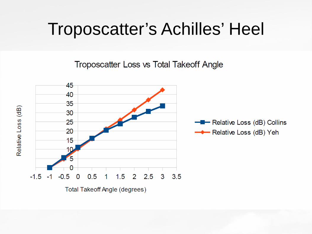
Troposcatter’s Achilles’ Heel

If we subtract 10 dB of signal from Tropo for Take Off Angle of only 1 degree or add 20 dB of signal to AS for Forward Scatter Enhancement,Balance shifts in favor of AS even for lower frequencies and shorter distances!
But if the aircraft’s RCS is lower than expected, then balance shifts in favor of troposcatter

Forward Scatter EnhancementAircraft Scattering Angle


Aircraft Scattering Angle

Take-home message:
Keep YOUR skew angle less than 3-5 degrees to keep FSE within 10 dB of maximum possible value
There is also a distance effect, but it is weaker than the skew-angle effect
Remember, AS Angle depends on the SUM of your skew angle PLUS your partner’s skew angle


FSE 144 MHz
FSE 10 GHz
Beamwidth = 14.36 * λ / radius

12/13 results were within 10 dB
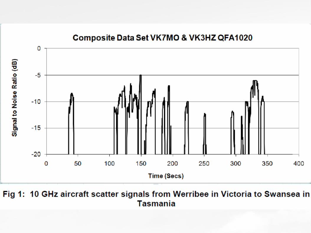
Theory vs Reality - VK7MO144 thru 1296 MHz
Moncur R. Aircraft Enhancement – Some Insights from Bistatic Radar Theory.CQ VHF Magazine Fall 2003.
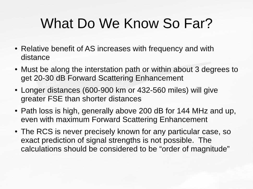
What Do We Know So Far?
● Relative benefit of AS increases with frequency and with distance
● Must be along the interstation path or within about 3 degrees to get 20-30 dB Forward Scattering Enhancement
● Longer distances (600-900 km or 432-560 miles) will give greater FSE than shorter distances
● Path loss is high, generally above 200 dB for 144 MHz and up, even with maximum Forward Scattering Enhancement
● The RCS is never precisely known for any particular case, so exact prediction of signal strengths is not possible. The calculations should be considered to be “order of magnitude”

Complications
● Antenna Pointing● Doppler Shift

Is Pointing at the Aircraft Necessary?
Elevation and Scattering Angle vs Distance for Aircraft Altitude 10,000 meters
QSO Distance 200 km 400 km 600 km 800 km 1000 km
Distance to Aircraft 100 km 200 km 300 km 400 km 500 km
Elevation 5.4 2.2 0.9 0.08 -0.54
Scattering Angle 11.2 5.6 3.8 2.8 2.3 *
Maximum Forward Scattering Enhancement
15 21 25 27 29 *
Consider both Elevation and Horizontal Skew compared with beamwidth of antenna array

Complications: Doppler Shift
● Aircraft speeds 600-1100 km/h (370-680 mph)
● Δf = (1/λ) * (VTx + VRx)
λ = wavelength
VTx = Plane’s Velocity component along path from aircraft to Tx station
VRx = Plane’s Velocity component along path from aircraft to Rx station
● When plane is moving along the direct path between Tx and Rx stations, the two Doppler Velocities cancel out
● When plane is moving perpendicular to the direct path between the Tx and Rx stations, the two Doppler Velocities ADD
● This is another HUGE reason why it is GREAT when you can make use of a plane traveling along the direct path between your station and your QSO partner’s station

Maximum Doppler Shift (Hz)Flight Perpendicular to Interstation Path
(Single Station Component)MHz km/h 600 700 800 900 1000
50 28 32 37 42 46
144 80 93 107 120 133
222 123 144 164 185 206
432 240 280 320 360 400
903 502 585 669 753 836
1296 720 840 960 1080 1200
2304 1280 1493 1707 1920 2133
3456 1920 2240 2560 2880 3200
5760 3200 3733 4267 4800 5333
10368 5760 6720 7680 8640 9600
24192 13440 15680 17920 20160 22400

Maximum Doppler ShiftSingle Station Component

Doppler Shift (Hz) Flight Perpendicular to Interstation Path
(Both Station Components)
MHz km/h 600 700 800 900 1000
50 56 65 74 83 93
144 160 187 213 240 267
222 247 288 329 370 411
432 480 560 640 720 800
903 1003 1171 1338 1505 1672
1296 1440 1680 1920 2160 2400
2304 2560 2987 3413 3840 4267
3456 3840 4480 5120 5760 6400
5760 6400 7467 8533 9600 10667
10368 11520 13440 15360 17280 19200
24192 26880 31360 35840 40320 44800

Maximum Doppler ShiftBoth Station Components


16.48 Hz/second change in Doppler Shift is 247 Hz during a single 15 second ISCAT-A cycle
Compare to 0.006 Hz/ second for “parallel” flight path example just shown which gives change of 0.09 Hz over 15 second cycle

Doppler shift at 10 GHz for 1000 km/h = 9260 Hz * 2 = 18,530 Hz
Change speed by 1% to 1010 km/h and Doppler changes by 1%, or 185 Hz!


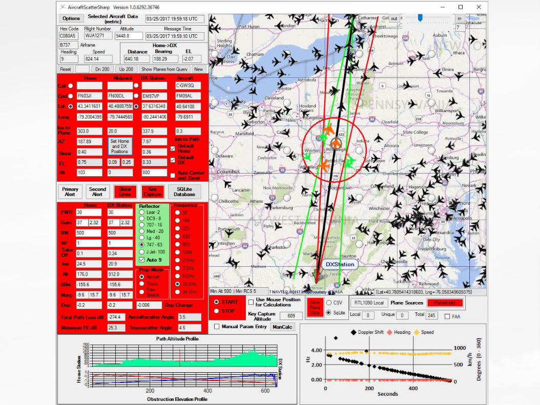
Manual Calculations and Calculations on SQLite Database Aircraft
Examples for RF Calculations, Max FSE,Tropo Angle, Doppler

Digital Modes and AS

Reasons to use Digital Modes for Aircraft Scatter
● Pull weak signals out of the noise
● Short chopped signal segments on upper bands
● Because it’s cool

Complications to using Digital Modes with Aircraft Scatter
● Doppler shift● Short chopped up signal blocks● Short period to complete QSO if plane flying
perpendicular to interstation path

Which Digital Mode to Use?
For Microwaves, ISCAT is preferred due to its tolerance for Doppler shifts, its 15 second periods and ability to cope with short bursts. MSK144 can’t handle the Doppler shifts and JT65 is too slow and can’t handle bursts. *with 30s average #for 70/500 ms burst &20 ms burst
Mode Spacing BW (Hz) Baud rate) Duration (s) S/N (dB)
JT4A 4.38 17.5 4.38 47.1 -23
JT9A 1.74 15.6 1.74 49 -27
JT65A 2.69 177.6 2.69 46.8 -25
QRA64A 1.74 111.1 1.74 48.4 -26
ISCAT-A 21.5 905 21.5 1.18 -17*
ISCAT-B 43.1 1809 43.1 0.59 -17*
JT9E 27.78 224 25 3.4 -23
JT9F 55.56 446.2 50 1.7 -22
JT9G 111.11 890.6 100 0.85 -21
JT9H 222.22 1779.5 200 0.43 -20
MSK144 2000 0.07 -2/-8#
MSK144 Sh 2000 0.02 -2&
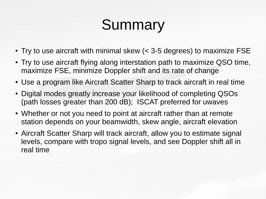
Summary
● Try to use aircraft with minimal skew (< 3-5 degrees) to maximize FSE● Try to use aircraft flying along interstation path to maximize QSO time,
maximize FSE, minimize Doppler shift and its rate of change● Use a program like Aircraft Scatter Sharp to track aircraft in real time● Digital modes greatly increase your likelihood of completing QSOs
(path losses greater than 200 dB); ISCAT preferred for uwaves● Whether or not you need to point at aircraft rather than at remote
station depends on your beamwidth, skew angle, aircraft elevation● Aircraft Scatter Sharp will track aircraft, allow you to estimate signal
levels, compare with tropo signal levels, and see Doppler shift all in real time

Preferred Mode vs Band / Distance
MHz km 300 or less 500 700 900
50 T T / M M M
144 T A M / A M
222 T A A A#
432 T A A A#
903 T / A* A A A#
1296 and up T / A* A A A#
T = TS, A=AS, M = MS. * TS will be favored over AS for high aircraft elevation angles # AS will be useful if the aircraft is above the horizon for both stations

Questions?
Mach 9.6 (11,850 km/h)

Not just any Magic, but Physics Magic
When the forward scattering angle is 180 degrees:We get constructive interference of the scattered radiation, called“Diffractive Scattering” which gives us Forward scatter enhancement = 4*Pi* A/(lambda**2)
For 1296 MHz, if there is 29-49 dB enhancement, then 8 dB signal margin becomes 37-57 dB signal margin


Something for Nothing?
• Beamwidth (in degrees) = (14.32 * lambda) / (radius)
Frequency MHz 144 432 1296 2304 3G 5G 10G
Radius
1 meter 3 dB beamwidth deg 29.842 9.947 3.316 1.865 1.243 0.746 0.414
5 meters 3 dB beamwidth deg 5.9683 1.989 0.663 0.373 0.249 0.149 0.083
10 meters 3 dB beamwidth deg 2.9842 0.995 0.332 0.187 0.124 0.075 0.041


