

UserManual
DeviceNetStarter Kit
(Cat. No. 1787-STARTKIT1)
Allen-Bradley

Solid state equipment has operational characteristics differing fromthose of electromechanical equipment. “Safety Guidelines for theApplication, Installation and Maintenance of Solid State Controls”(Publication SGI-1.1) describes some important differences betweensolid state equipment and hard–wired electromechanical devices.Because of this difference, and also because of the wide variety ofuses for solid state equipment, all persons responsible for applyingthis equipment must satisfy themselves that each intendedapplication of this equipment is acceptable.
In no event will the Allen-Bradley Company be responsible or liablefor indirect or consequential damages resulting from the use orapplication of this equipment.
The examples and diagrams in this manual are included solely forillustrative purposes. Because of the many variables andrequirements associated with any particular installation, theAllen-Bradley Company cannot assume responsibility or liability foractual use based on the examples and diagrams.
No patent liability is assumed by Allen-Bradley Company withrespect to use of information, circuits, equipment, or softwaredescribed in this manual.
Reproduction of the contents of this manual, in whole or in part,without written permission of the Allen-Bradley Company isprohibited.
Throughout this manual we use notes to make you aware of safetyconsiderations.
!ATTENTION: Identifies information about practicesor circumstances that can lead to personal injury ordeath, property damage, or economic loss.
Attentions help you:
• identify a hazard
• avoid the hazard
• recognize the consequences
Important: Identifies information that is especially important forsuccessful application and understanding of the product.
PLC, PLC-5, SLC, SLC 500, SLC 5/02, SLC 5/03, SLC 5/04, 800T RediSTATION, DeviceLink and DeviceNetManagerare trademarks of Allen-Bradley Company, Inc.
IBM is a registered trademark of International Business Machines, Incorporated.
Microsoft is a registered trademark of Microsoft Corporation.
Windows, Windows 95 and Windows NT are trademarks of Microsoft Corporation.
DeviceNet is a trademark of the Open DeviceNet Vendor Association (O.D.V.A.).
Important User Information

Publication DN-6.9.1 – June 1996
Chapter 1
What this Chapter Contains 1–1. . . . . . . . . . . . . . . . . . . . . . . . . . . . . What Is DeviceNet? 1–1. . . . . . . . . . . . . . . . . . . . . . . . . . . . . . . . . . . What Hardware and Software You Need
to Make Use of Your Starter Kit 1–2. . . . . . . . . . . . . . . . . . . . . . . . What We Assume You Know and Have Done 1–2. . . . . . . . . . . . . . . . . Tool You Must Provide 1–3. . . . . . . . . . . . . . . . . . . . . . . . . . . . . . . . . Identify the Starter Kit Components 1–3. . . . . . . . . . . . . . . . . . . . . . . . Identify the Components You Must Provide 1–3. . . . . . . . . . . . . . . . . . What You Will Be Doing in this Manual 1–4. . . . . . . . . . . . . . . . . . . . . Complete the Starter Kit Survey Diskette 1–4. . . . . . . . . . . . . . . . . . . . Rely on A-B Quality and DeviceNet Support 1–5. . . . . . . . . . . . . . . . . .
Related Publications 1–5. . . . . . . . . . . . . . . . . . . . . . . . . . . . . . . . Summary and What’s Next 1–6. . . . . . . . . . . . . . . . . . . . . . . . . . . . . .
Chapter 2
What this Chapter Contains 2–1. . . . . . . . . . . . . . . . . . . . . . . . . . . . . Illustrated Objective 2–1. . . . . . . . . . . . . . . . . . . . . . . . . . . . . . . . . . . Connect the Trunkline 2–2. . . . . . . . . . . . . . . . . . . . . . . . . . . . . . . . . Connect the Drop Lines 2–3. . . . . . . . . . . . . . . . . . . . . . . . . . . . . . . . Summary and What’s Next 2–4. . . . . . . . . . . . . . . . . . . . . . . . . . . . . .
Chapter 3
What this Chapter Contains 3–1. . . . . . . . . . . . . . . . . . . . . . . . . . . . . Illustrated Objective 3–1. . . . . . . . . . . . . . . . . . . . . . . . . . . . . . . . . . . Connect the 1770-KFD and Personal Computer 3–2. . . . . . . . . . . . . . . Connect the 1747-SDN Scanner Module 3–3. . . . . . . . . . . . . . . . . . . . Connect the Power Supply 3–4. . . . . . . . . . . . . . . . . . . . . . . . . . . . . . Ground the Starter Kit 3–5. . . . . . . . . . . . . . . . . . . . . . . . . . . . . . . . . Apply System Power 3–5. . . . . . . . . . . . . . . . . . . . . . . . . . . . . . . . . .
Check Scanner Module Diagnostics 3–6. . . . . . . . . . . . . . . . . . . . . Set Up an On-line Connection 3–6. . . . . . . . . . . . . . . . . . . . . . . . . . . . Perform a Network Who 3–9. . . . . . . . . . . . . . . . . . . . . . . . . . . . . . . . Summary and What’s Next 3–10. . . . . . . . . . . . . . . . . . . . . . . . . . . . . .
Before You Begin
Connect the PhysicalMedia
Set Up an OnlineConnection
Table of Contents

ii
Publication DN-6.9.1 – June 1996
Chapter 4
What this Chapter Contains 4–1. . . . . . . . . . . . . . . . . . . . . . . . . . . . . Illustrated Objective 4–1. . . . . . . . . . . . . . . . . . . . . . . . . . . . . . . . . . . Configure the 800T RediSTATION 4–2. . . . . . . . . . . . . . . . . . . . . . . . . Connect the 800T RediSTATION 4–3. . . . . . . . . . . . . . . . . . . . . . . . . .
Check the Node Address of the RediSTATION 4–4. . . . . . . . . . . . . . Connect the Series 9000 Photoelectric Sensor 4–5. . . . . . . . . . . . . . . .
Check the Node Address of the Photoelectric Sensor 4–6. . . . . . . . . Perform Node Commissioning 4–6. . . . . . . . . . . . . . . . . . . . . . . . .
Connect the DeviceLink I/O and Limit Switch 4–9. . . . . . . . . . . . . . . . . Check the Node Address of the DeviceLink I/O 4–10. . . . . . . . . . . . . Perform Node Commissioning 4–10. . . . . . . . . . . . . . . . . . . . . . . . .
Summary and What’s Next 4–13. . . . . . . . . . . . . . . . . . . . . . . . . . . . . .
Chapter 5
What this Chapter Contains 5–1. . . . . . . . . . . . . . . . . . . . . . . . . . . . . Configure the Series 9000 Photoelectric Sensor 5–1. . . . . . . . . . . . . . . Monitor the Status of the Photoelectric Sensor 5–4. . . . . . . . . . . . . . . . Configure the DeviceLink I/O 5–5. . . . . . . . . . . . . . . . . . . . . . . . . . . . Monitor the Status of the DeviceLink I/O 5–7. . . . . . . . . . . . . . . . . . . . Configure the 1747-SDN Scanner Module 5–8. . . . . . . . . . . . . . . . . . . Summary and What’s Next 5–13. . . . . . . . . . . . . . . . . . . . . . . . . . . . . .
Chapter 6
What this Chapter Contains 6–1. . . . . . . . . . . . . . . . . . . . . . . . . . . . . Create the Ladder Logic Program 6–2. . . . . . . . . . . . . . . . . . . . . . . . . Use APS and DeviceNet Manager to Perform and Monitor DeviceNet
Control and Diagnostics 6–4. . . . . . . . . . . . . . . . . . . . . . . . . . . . . Rung 0 6–4. . . . . . . . . . . . . . . . . . . . . . . . . . . . . . . . . . . . . . . . . . Rung 2 6–4. . . . . . . . . . . . . . . . . . . . . . . . . . . . . . . . . . . . . . . . . . Rung 3 6–5. . . . . . . . . . . . . . . . . . . . . . . . . . . . . . . . . . . . . . . . . . Rung 4 6–6. . . . . . . . . . . . . . . . . . . . . . . . . . . . . . . . . . . . . . . . . .
Summary 6–7. . . . . . . . . . . . . . . . . . . . . . . . . . . . . . . . . . . . . . . . . .
Connect the Devices andPerform NodeCommissioning
Configure and Monitor theDevices withDeviceNetManager
Use APS andDeviceNetManager forControl and Diagnostics

Chapter 1
Publication DN-6.9.1 – June 1996
���� �� �����
This chapter describes what you must know and do before you beginto use your starter kit. The following table describes what thischapter contains and its location.
For information about See pageDeviceNetTM network 1–1what you need to use this starter kit 1–2what we assume you know and have done 1–2identifying the starter kit components 1–3identifying what components you must provide 1–3what you will be doing in this manual 1–4completing the survey diskette 1–4Allen-Bradley quality and DeviceNet support 1–5chapter summary and what’s next 1–6
DeviceNet is a low-end, open network providing connectionsbetween simple, primarily discrete industrial devices and controllerswithout the need for intervening I/O modules or blocks. Simpledevices include products such as sensors and actuators.
The intent of this network is to provide an alternate way for controlengineers to connect simple devices to their control systems. TheDeviceNet network:
• supports devices that are becoming more intelligent
• facilitates increasingly precise troubleshooting to reducedown-time (a communication fault can be traced to a singledevice rather than to the rack or block level as with an I/O network)
• reduces installation and startup costs and time (compared totraditional I/O wiring, especially when devices are spread overseveral hundred feet)
What this ChapterContains
What Is DeviceNet?

1–2 Before You Begin
Publication DN-6.9.1 – June 1996
The following table lists what materials you need to follow theprocedures described in this manual. Notice which products aresupplied in the DeviceNet starter kit and which you must provide.
Product Quantity Part number
Provided in the Starter Kit 1T-port tap (right keyway) 5 1485P-P1N5-MN5R1mini-male to conductor 1m drop cable 4 1485R-P1M5-Cmini-male to micro female 1m drop cable 4 1485R-P1M5-R5terminator, female 2 1485A-T1N53-receptacle 5-wire terminal block 1 1492-DNTB3DeviceLink I/O mini-male to mini female 1 1485D-A1M5-R4limit switch, mini-male 1 802T-APJ1Series 9000 Diffuse Photoelectric sensor 1 42GNP-9000-QD800T RediSTATION 1 2705-T3DN1A42Athis user manual 1 DN-6.91Feedback Disk with DeviceNet survey 1 CSV-683
What You Must Provide24 volt, DC power supply (<3amp output) 1 n/awires for power supply (18 gauge recommended) 3 n/aSLC chassis 1 1746-A4, -A7, -A10, -A13SLC 5/02 , 5/03 , or 5/04 processor 1 1747-L524, -L532, -L542SLC DeviceNet scanner1 1 1747-SDNSLC chassis power supply 1 1746-P1, -P2, -P3, -P4SLC programming software2 1 APS or AI5IBM compatible PC 1 n/aMicrosoft WindowsTM (3.1 or later), Windows NTTM or Window ’95TM software 1 n/aDeviceNetManagerTM software1 1 1787-MGRRS-232 interface module1 1 1770-KFDPC-to-SLC programming connection3 1 n/a3
1 This product is included with DeviceNet Starter Kit 2 or 3.2 APS software is used in this manual’s examples.3 Due to the varied possibilities, the components for your PC-to-processor communication link do not appear in the table
above or the following illustrations. Your existing PC-to-processor connection is compatible with this document’sprocedures and configurations.
Important: You can use this starter kit with a PLC chassis,processor and 1771-SDN scanner module. Differencesare based on PLC technology (scanner mapping andPLC programming). These variations are describedwhere applicable in this user manual.
You can use this starter kit with any DeviceNet master. Refer to youruser documentation for more information.
The descriptions in this user manual assume that you know how toinstall and use all of the hardware and software that you mustprovide (listed above). We also assume you have these itemsinstalled and ready.
If you do not, read the documentation associated with these itemsand have them installed and ready to use before you attempt toassemble your starter kit.
What Hardware andSoftware You Needfor YourStarter Kit
What We Assume YouKnow and Have Done

1–3Before You Begin
Publication DN-6.9.1 – June 1996
To connect the wiring in this starter kit, you’ll need a small,flat-blade screwdriver.
Unpack your starter kit and use the following illustration to identifyall of the components you should have received. Contact your localAllen-Bradley representative if any item is missing.
800T RediSTATION withmini-male connector (1)
ÎÎÎ
Mini-male to conductor, 1m drop (2)
ÎÎÎÎÎÎ
T-port tap (5)
Series 9000 Photoelectric sensormicro-male (1)
DeviceLink I/O mini-male to mini-female (1)
Limit switchmini-male (1)
ÎÎÎÎ
3-receptacle 5-wireterminal block (1)
ÎÎÎÎÎÎ
ÎÎMini-male to micro-female (1)
Female terminator (2)
This user manual (1)
floppy disk withsurvey (1)
ÎÎÎÎ
ÎÎ
Use the following illustration to identify all of the hardware andsoftware you must provide.
1770-KFDInterface Module*
24 Volt, DCpower supplywith three wires(18-gaugerecommended)
PC with Windows (3.1) andprogramming softwareinstalled
Power Supply
1747-SDN DeviceNetScanner Module*
SLC 5/02, 5/03 or 5/04 Processor
DeviceNetManager Software*
SLC chassis
5-pin linear plug with probe holesand jack screws (included with1747-SDN Scanner Module)*
5-pin linear plug with probe holes(included with 1770-KFD module)*
SLC Programming Software*
* Included with Starter Kit 2 or 3.
Tool You Must Provide
Identify the Starter KitComponents
Identify the ComponentsYou Must Provide

1–4 Before You Begin
Publication DN-6.9.1 – June 1996
The following chapters describe how to setup up a simple DeviceNetnetwork and perform basic operations:
Start
Chapter 2
Complete
Connect thePhysical Media
Chapter 3
Set Up anOnlineConnection
Chapter 4
ConnectDevices andCommissionNodes
Chapter 5
Configure theDevices withDeviceNetManager
Chapter 1
Before YouBegin
Chapter 6
Use APS andDeviceNetManager
Your starter kit contains a Feedback Disk with a Windows-basedsurvey. This survey is designed to get your comments on the starterkit, the DeviceNet network and Allen-Bradley products and services.We will use your input for future product and service development.
Please complete the survey by answering all the questions, enclosingthe disk in the self-addressed stamped envelope and mailing it.Allen-Bradley guarantees complete confidentiality of all informationon the survey disk.
Business Reply Mail
DeviceNet
Feedback Disk
self-addressedreturn envelope
What You Will Be Doing inthis Manual
Complete the Starter KitFeedback Disk

1–5Before You Begin
Publication DN-6.9.1 – June 1996
We have helped numerous customers around the world achieve theirmanufacturing goals. For assistance with A-B DeviceNet products,call your local distributor or sales office.
Our support network offers complete system integration andsupport services including application engineering, installationsupervision, system startup, training, field service, and ongoingproduct support.
You can access an A-B sales representative, appointeddistributor, or authorized system integrator almost anywherearound the world. Perhaps that’s why A-B is the preferredsupplier of automation controls in the industry.
We’re global because we’re local to you.
Related Publications
Title PublicationNumber
DeviceNet Product Overview DN-2.5
DeviceNet Sealed Physical Media Bulletin 1485 Product Profile DN-1.8
DeviceNet Media System Vendor List DN-2.1
PHOTOSWITCH Series 9000 Photoelectric Sensors for theDeviceNet Network Product Profile
DN-1.11
DeviceNet RediSTATION Product Profile DN-1.13
DeviceNet Communication Link Overview Product Profile DN-1.18
DeviceLink I/O Product Profile DN-1.15
DeviceNet Scanner for 1771 Chassis Product Profile DN-1.7
Open DeviceNet Vendor Association Catalog CSV-654
Open Device Network Offers Improved Communications andFlexibility Product Profile
DN-1.9
Rely on A-B Quality andDeviceNet Support

1–6 Before You Begin
Publication DN-6.9.1 – June 1996
In this chapter, you learned:
• about the DeviceNet network
• what you need to use this starter kit
• what we assume you know and have done
• to identify the starter kit components
• to identify the components you must provide
• what you will be doing in this manual
• how to complete the starter kit survey diskette
• about Allen-Bradley quality and DeviceNet support
Move on to Chapter 2 to learn how to connect the physical media.
Summary and What’s Next

Chapter 2
Publication DN-6.9.1 – June 1996
� ����� �� ������ ����
The following table describes what this chapter contains and itslocation.
For information about: See pagewhat the network will look like 2–1connecting the trunk line 2–2connecting the drop lines 2–3chapter summary and what’s next 2–4
Use the illustration below to see how your DeviceNet network willlook after following this chapter’s procedures.
Mini-male toopen conductor
ÏÏÏ
ÏÏÏÏ
ÏÏÏÏ
ÏÏÏÏÏÏ
ÏÏÏÏ
ÏÏfemale
terminatingresistor
ÏÏ
ÏÏÏÏÏÏ female
terminatingresistor
T-port tap
ÏÏMini-male to
open conductorÏÏÏÏ
mini-male tomicro-femaledrop line
ÏÏ
ÏÏÏÏ
ÏÏÏÏ
Mini-male to open conductor drop lines (2)
5-pin linear plug
3-receptacle, 5-wireterminal block
5-pin linear plugwith jack screws
T-port tap T-port tap T-port tap T-port tap
What this ChapterContains
Illustrated Objective

2–2 Connect the Physical Media
Publication DN-6.9.1 – June 1996
Gather the following components from your starter kit:
ÏÏÏÏ
ÏÏ
T-port taps (5)
ÏÏ
3-receptacle 5-wireterminal block (1)
Female terminators (2)
Mini-male toopen conductors (2)ÏÏ
ÏÏ
ÏÏ
ÏÏ
ÏÏ
ÏÏ
ÏÏ
ÏÏ
ÏÏ
ÏÏ
ÏÏ
Use the following illustration as a guide to connect the trunk line:
1. Insert and hand-tighten the T-porttaps to each other in groups of twoand three.
2. Connect colored wiring on openconductors to matching terminals onthe terminal block.
3. Attach terminators to each end of therow of T-port taps.
Important When terminating a DeviceNetsystem, do not put a terminatingresistor on a node. Doing so risksnetwork failure if you remove thenode. The resistor must be at the endof the trunk line.
BLACKBLUEDRAINWHITE
RED
Mini-male toopen conductor
ÏÏÏÏ
ÏÏÏÏÏÏ
ÏÏÏÏ
ÏÏÏÏ
ÏÏÏÏ
ÏÏÏÏ
female terminating
resistor
ÏÏ
ÏÏÏÏ
female terminatingresistor
T-port tapÏÏÏÏ
Mini-male toopen conductor
REDWHITEDRAINBLUEBLACK
How to wire the terminal block:
terminal block
Basic steps
1st terminal stripand receptacle (left)
2nd terminal stripand receptacle (center and rear)
Connect this T-port tap to thismini-male connector
T-port tap
T-port tap T-port tap T-port tap
Connect the Trunk Line

2–3Prepare Your Physical Media
Publication DN-6.9.1 – June 1996
To connect the drop lines, gather the following components:
mini-male tomicro-femaledrop line
ÏÏÏÏ
ÏÏ
Mini-male toopen conductordrop lines (2)
5-pin linear plug
ÏÏ
5-pin linear plugwith jack screws
Included with your starter kit
Included with your 1770-KFD module
Included with your 1747-SDN module
Use the following illustration as a guide to attach the drop lines tothe trunk line:
BLACK
Mini-male toopen conductor
ÏÏÏÏ
ÏÏÏÏ
ÏÏÏÏÏÏ
ÏÏÏÏ
ÏÏÏÏ
ÏÏÏÏfemale
terminatingresistor
ÏÏ
ÏÏÏÏ female
terminatingresistor
T-port tap
ÏÏMini-male to
open conductor
How to wire the 5-pin linear plugs:
ÏÏ
mini-male tomicro-femaledrop line
ÏÏ
ÏÏ ÏÏ
Mini-male to open conductor drop lines (2)
RED
WHITE
DRAIN
BLUE
terminal block
Basic steps
1. Insert and hand-tighten each conductor of amini-male-to-conductor drop line into theappropriate T-port tap.
2. Wire the 5-pin linear plug according to theillustration on the right. Make sure the wiring colorsequence matches the color sequence on thelabel of the 1770-KFD module.
3. Wire the 5-pin linear plug with jack screwsaccording to the illustration on the right. Makesure the wiring color sequence matches the colorsequence on the label of the 1747-SDN module.
5-pin linear plug
5-pin linear plugwith jack screws
T-port tap T-port tap T-port tap T-port tap
BLACK
RED
WHITE
DRAIN
BLUE
Connect the Drop Lines

2–4 Connect the Physical Media
Publication DN-6.9.1 – June 1996
In this chapter, you learned how to:
• understand what the network will look like
• connect the trunk line components
• connect the drop lines
Move on to Chapter 3 to learn how to set up an online connection.
Summary and What’s Next

Chapter 3
Publication DN-6.9.1 – June 1996
��� � �� ���� ���������
The following table describes what this chapter contains and itslocation.
For information about: See pagewhat the network will look like 3–1connecting the 1747-SDN scanner module 3–3connecting the power supply 3–4grounding the network 3–5applying system power 3–5setting up an online connection 3–6performing a Network Who 3–9chapter summary and what’s next 3–10
Use the illustration below to see how your DeviceNet network willlook after following this chapter’s procedures.
ÎÎ
Î
ÎÎÎÎÎ
ÎÎÎÎÎ
ÎÎ
Î
Î
ÎÎ
ÎÎ ÎÎ ÎÎ
Î ÎÎ
What this ChapterContains
Illustrated Objective

3–2 Set Up an Online Connection
Publication DN-6.9.1 – June 1996
To connect the 1770-KFD interface module:
1. Use the RS-232 cable to connect the 1770-KFD module to yourcomputer’s serial port.
RS-232 Cableto your computer
ÎÎ
ÎÎ
Dropline
1770-KFDinterface module
RS-232
2. Use one of the 5-pin linear plugs (attached to the mini-male toopen conductor) to connect the 1770-KFD module to the trunkline.
ÎÎÎÎ
Dropline
Mini-male toopen conductor with 5-pin linearplug attached.
Be sure the wiring orientation onthe plug matches the wiring colorscheme on the 1770-KFDmodule.
1770-KFDinterface module
Mini-male to openconductor with 5-pinlinear plug attached
RS-232 Cable
Connect the 1770-KFD andPersonal Computer

3–3Set Up an Online Connection
Publication DN-6.9.1 – June 1996
To connect the scanner module:
1. Be sure that the SLC chassis power is off.
!ATTENTION: Do not wire the 1747-SDNScanner Module with the network power supply on.Wiring the module with the network power supplyon may short your network or disruptcommunication.
2. Connect the 1747-SDN Scanner Module to the 5-pin linear plug(attached to the mini-male open conductor) as shown in the areaof detail below:
ÎÎÎÎ
ÎÎÎ
ÎÎÎÎÎ
ÎÎÎÎ
ÎÎÎÎ
ÎÎ
ÎÎÎÎ
ÎÎÎÎÎÎ
ÎÎ
ÎÎÎÎ
ÎÎÎÎ
ChassisPowerSupply
1747-SDN DeviceNetScanner Module
SLC 5/02, -5/03 or -5/04 Processor
SLC chassis
Dropline
5-pin linear plugDeviceNetport
Mini-male to open conductorwith 5-pin linear plug with jackscrews.
Be sure the wiring orientation onthe plug matches the wiring colorscheme on the 1747-SDNScanner Module module.
3. Tighten the jack screws on the 5-pin linear plug.
For installation informationon the 1771-SDN scannermodule, refer to theInstallation Instructions,publication 1771-5.14.
Connect the 1747-SDNScanner Module

3–4 Set Up an Online Connection
Publication DN-6.9.1 – June 1996
Connect the 24Vdc power supply to the terminal block as shown inthe area of detail below:
!ATTENTION: The cabling in the DeviceNet starterkit is rated at 3 amps. Be sure your power supplyoutput current does not exceed 3 amps.
ÎÎÎÎÎ
ÎÎÎÎÎ
ÎÎÎÎÎ
ÎÎÎÎÎ
ÎÎÎÎÎ
ÎÎ ÎÎÎÎ ÎÎ
ÎÎ ÎÎ
24Vdcpowersupply
To power source
RED (24Vdc)
DRAIN (GND)
BLACK (0Vdc)
3rd terminal stripand receptacle(right and front)
RAIL 3
RAIL 3
Connect the Power Supply

3–5Set Up an Online Connection
Publication DN-6.9.1 – June 1996
You must ground your DeviceNet network at only one location.
To ground the network:
• Connect the network shield and drain wire to an earth or buildingground using a 0.25mm (1in) copper braid or a #8 AWG wire upto 3m (10ft) maximum in length
• Use the same ground for the V– conductor of the cable systemand the dc ground of the power supply.
Apply power to the devices you just installed in your DeviceNetsystem:
• 24V dc power supply
• 1770-KFD interface module
• personal computer
• SLC chassis with power supply and scanner module installed
ÎÎÎ
ÎÎÎÎÎÎ
ÎÎÎÎÎÎÎÎÎ ÎÎ Î
ÎÎÎÎ
1770-KFD interfacemodule
Personal ComputerPowerSupply
1747-SDN DeviceNetScanner Module
SLC 5/02, 5/03 or 5/04 Processor
24Vdc power supply
signalsignaldrain
V–V+
V+V–
class 2 power supply
schematic
L1L2grd
120V ac(typical)
Ground the Network
Apply System Power

3–6 Set Up an Online Connection
Publication DN-6.9.1 – June 1996
Check Scanner Module Diagnostics
Observe the diagnostics on the scanner module:
• the node address and status display should be alternately flashingbetween 00 and 75
• the module status indicator should illuminate solid green
• the network status should be flashing green
Top part of module
DeviceNet
STATUSMODULE NET
ADDRESS/ERROR
Node Addressand StatusDisplay
Follow these steps to go on line:
1. Start DeviceNetManager software.
2. From the Utilities menu, choose Set Up Online Connection.For installation informationon DeviceNetManagerSoftware, refer to theDeviceNetManager UserManual, publication1787-6.5.3.
Set Up an On-lineConnection

3–7Set Up an Online Connection
Publication DN-6.9.1 – June 1996
You see this screen:
The node address for the 1770-KFD module should be 62.
Is the Node Address for your1770-KFD 62?
Choose
Yes
No the new address by scrolling to 62 in theNode Address dialog box:
Change your project path.
and then:
You see this screen:
3–8 Set Up an Online Connection
Publication DN-6.9.1 – June 1996
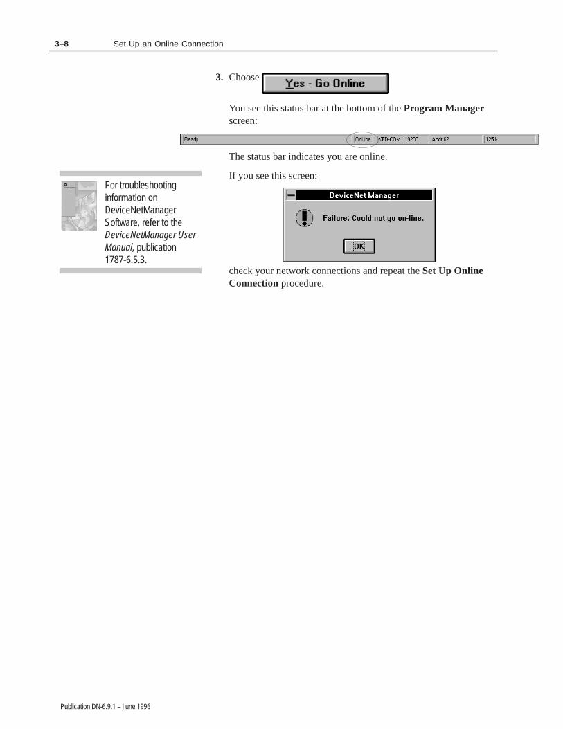
3. Choose
You see this status bar at the bottom of the Program Managerscreen:
The status bar indicates you are online.
If you see this screen:
check your network connections and repeat the Set Up OnlineConnection procedure.
For troubleshootinginformation onDeviceNetManagerSoftware, refer to theDeviceNetManager UserManual, publication1787-6.5.3.

3–9Set Up an Online Connection
Publication DN-6.9.1 – June 1996
Perform a Network Who to verify that the 1747-SDN ScannerModule and DeviceNetManager software are on the network.
1. From the Who menu, select Network Who.
You see this screen:
2. After the 1747-SDN Scanner Module and DeviceNetManagersoftware devices appear on the network, click on
If one or both of the devices do not appear, check theirconnections and repeat the Network Who procedure.
Perform a Network Who

3–10 Set Up an Online Connection
Publication DN-6.9.1 – June 1996
In this chapter, you learned how to:
• connect the 1770-KFD and your personal computer
• connect the 1747-SDN scanner module
• connect the power supply
• ground the network
• apply system power
• set up an on-line connection
• perform a Network Who
• chapter summary and what’s next
Move on to Chapter 4 to learn how to connect the devices.
Summary and What’s Next

Chapter 4
Publication DN-6.9.1 – June 1996
������ �� �� �� �������� ��� ���� �� �� ��
The following table describes what this chapter contains and itslocation.
For information about: See pagewhat the network will look like 4–1configuring the 800T RediSTATION operator interface 4–2connecting the 800T RediSTATION operator interface 4–3connecting the Series 9000 photoelectric sensor andperforming node commissioning
4–5
connecting the DeviceLink I/O and limit switch andperforming node commissioning
4–9
chapter summary and what’s next 4–13
Use the illustration below to see how your DeviceNet network willlook after following this chapter’s procedures.
ÎÎÎÎ
ÎÎÎÎÎ
ÎÎÎÎÎ
ÎÎÎÎ
ÎÎÎÎ
ÎÎ
ÎÎÎÎ
ÎÎÎÎ
ÎÎ
Î
Î
800TRediSTATION
operator interfacewith mini-male
connector
ÎÎ ÎÎ
Series 9000Photoelectric
sensormicro-male
Limit switchmini-male
Drop line DeviceLinkI/O
Î
Î
What this ChapterContains
Illustrated Objective

4–2 Connect the Devices and Perform Node Commissioning
Publication DN-6.9.1 – June 1996
You must configure the RediSTATION operator interface’s DIPswitches before it can go online. This configuration is itscommissioning. The RediSTATION operator interface is notcommissioned through the software. Switch-configured valuesinclude:
• node address
• baud rate
• output fault-state
• output flash-rate
To configure your RediSTATION operator interface:
1. Remove the RediSTATION operator interface’s enclosure cover:
A. Using a slotted screwdriver, remove the six cover screws.
B. Carefully remove the cover so as not to disconnect any wires.
C. To easily access the DIP switches, disconnect the 5-pin linearplug from the circuit board.
2. Set the DIP switches to match the illustration below.
!ATTENTION: Do not use a pencil to set theRediSTATION operator interface’s DIP switches.Graphite from the pencil is conductive and maydamage the switch.
In this manual’s example, these dip switch settings indicate that:
• the node address is 15
• the baud rate is 125 Kb
• the output fault-state is off
• the output flash rate is 1 hz (0.5 seconds on and 0.5 secondsoff)
3. Re-attach the 5-pin linear plug to the circuit board.
4. Use the six cover screws to re-attach the enclosure to the station’scover.
For more detailed information about setting DIP switches, refer tothe RediSTATION Operator Interface User Manual.
9
OFF = 0
ON = 1101 2 3 4 5 6 7 8
node address
baud rate
output fault state
outputflash rate
6 Cover Screws
9
DeviceNet Connector
LED
Cover
DIP Switches
OFF = 0
ON = 1101 2 3 4 5 6 7 8
5-pin linear plug
Configure the 800TRediSTATION OperatorInterface

4–3Connect the Devices and Perform Node Commissioning
Publication DN-6.9.1 – June 1996
Connect the 800T RediSTATION operator interface to themini-female end of the T-port connector as shown in the area ofdetail below:
ÎÎÎÎÎ
ÎÎÎÎ
ÎÎÎÎ
ÎÎÎÎÎ
ÎÎÎÎ
ÎÎ
ÎÎ
ÎÎÎÎ
ÎÎÎÎ
Î ÎÎ
800TRediSTATION
operator interfacewith mini-male
connector
Connect the 800TRediSTATION OperatorInterface

4–4 Connect the Devices and Perform Node Commissioning
Publication DN-6.9.1 – June 1996
Check the Node Address of the RediSTATION Operator Interface
1. From the Who menu, select Network Who.
You see this screen:
2. After all three devices appear, click on
The node address for the RediSTATION operator interface is 15.You configured this node address on page 4–2.
3. Click on

4–5Connect the Devices and Perform Node Commissioning
Publication DN-6.9.1 – June 1996
Connect the Series 9000 Photoelectric Sensor to the micro-femaleend of drop line as shown in the area of detail below:
ÎÎÎÎ
ÎÎÎ
ÎÎÎÎÎ
ÎÎÎÎ
ÎÎÎÎ
ÎÎ
ÎÎÎÎ
ÎÎÎÎÎÎ
ÎÎ
ÎÎ
ÎÎ
ÎÎÎÎ
ÎÎÎÎ
Series 9000Photoelectric
sensormicro-male
Drop line
mini-male tomicro-femaleconductor
After you connect the photoelectric sensor to the network, look forthe illuminated and flashing indicators that indicate the sensor isfunctioning.
yellow - output
green - margin
red/green - status
Top of Photo sensor
Front of Photo sensor
Pass your hand in front of the sensor’s eye to block it. Observe howthe indicators change as you pass your hand back and forth.
Connect the Series 9000Photoelectric Sensor

4–6 Connect the Devices and Perform Node Commissioning
Publication DN-6.9.1 – June 1996
Check the Node Address of the Photoelectric Sensor
1. If you have not already done so, refer to Chapter 3 to set up anonline connection.
2. From the Who menu, select Network Who.
You see this screen:
3. After all four devices appear, click on
The node address for the photoelectric sensor should be 63. Thefollowing steps show you how to use DeviceNetManager tochange the node address to 07.
4. Click on
Perform Node Commissioning
Commission the node to change the node address.
1. From the Utilities menu, select

4–7Connect the Devices and Perform Node Commissioning
Publication DN-6.9.1 – June 1996
You see this screen:
2. In the Current Device Settings dialog box, scroll to the nodeaddress you want to change (in this example, 63).
3. In the New Device Settings dialog box, scroll to 07.
4. Click on
The status bar indicates Transaction Completed :
Status
5. Click on to verify the address has changed.

4–8 Connect the Devices and Perform Node Commissioning
Publication DN-6.9.1 – June 1996
You see this screen:
6. After all four devices appear, click on
7. Verify that the node address for the photoelectric sensor haschanged from 63 to 07.
8. Click on to close network who.
9. Click on to close node commissioning.
4–9Connect the Devices and Perform Node Commissioning
Publication DN-6.9.1 – June 1996
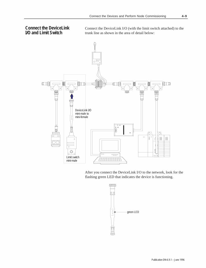
Connect the DeviceLink I/O (with the limit switch attached) to thetrunk line as shown in the area of detail below:
ÎÎÎÎÎ
ÎÎÎÎ
ÎÎÎÎ
ÎÎÎÎÎ
ÎÎÎÎ
ÎÎ
ÎÎ
ÎÎÎÎ
ÎÎÎÎ
ÎÎÎÎ
ÎÎÎÎ
ÎÎÎÎÎÎ
Limit switchmini-male
DeviceLink I/Omini-male tomini-female
ÎÎ
ÎÎ
After you connect the DeviceLink I/O to the network, look for theflashing green LED that indicates the device is functioning.
green LED
ÎÎ
ÎÎÎÎ
Connect the DeviceLinkI/O and Limit Switch

4–10 Connect the Devices and Perform Node Commissioning
Publication DN-6.9.1 – June 1996
Check the Node Address of the DeviceLink I/O
1. From the Who menu, select Network Who.
You see this screen:
2. After all five devices appear, click on
3. Click on
Perform Node Commissioning
You must change the node address for the DeviceLink I/O to 10.Commission the node to change the node address.
1. From the Utilities menu, select

4–11Connect the Devices and Perform Node Commissioning
Publication DN-6.9.1 – June 1996
You see the Device Configuration Node Commissioning screen:
2. In the Current Device Settings dialog box, scroll to the nodeaddress you want to change (the incorrect node address numberfor the DeviceLink I/O). In this example, the number is 63.
3. In the New Device Settings dialog box, scroll to 10.
4. Click on
The status bar indicates Transaction Completed :
Status
5. Click on to verify the address has changed.

4–12 Connect the Devices and Perform Node Commissioning
Publication DN-6.9.1 – June 1996
You see this screen:
6. After all five devices appear, click on
7. Verify that the node address for the DeviceLink I/O has changedfrom 63 to 10.
8. Click on to close network who.
9. Click on to close node commissioning.

4–13Connect the Devices and Perform Node Commissioning
Publication DN-6.9.1 – June 1996
In this chapter, you learned how to:
• understand what the network should look like
• configure the 800T RediSTATION operator interface
• connect the 800T RediSTATION operator interface
• connect the Series 9000 photoelectric sensor and perform nodecommissioning
• connect the DeviceLink I/O and limit switch and perform nodecommissioning
Move on to Chapter 5 to learn how to configure and monitor deviceswith the DeviceNetManager software.
Summary and What’s Next

4–14 Connect the Devices and Perform Node Commissioning
Publication DN-6.9.1 – June 1996

Chapter 5
Publication DN-6.9.1 – June 1996
�������� �� �������� ����� ��� ������������ �������
The following table describes what this chapter contains and itslocation.
For information about: See pageconfiguring the Series 9000 photoelectric sensor 5–1configuring the DeviceLink I/O 5–5configuring the 1747-SDN Scanner Module 5–8chapter summary and what’s next 5–13
Use DeviceNetManager software to change the configuration of thephotoelectric sensor:
1. From the Who menu, select Network Who.
You see this screen:
2. After all five devices appear, click on
3. Double-click on the Photoelectric Sensor to open its DeviceConfiguration – Enhanced Mode screen.
What this ChapterContains
Configure the Series 9000Photoelectric Sensor

5–2 Configure and Monitor the Devices with DeviceNetManager Software
Publication DN-6.9.1 – June 1996
You see this screen:
The photoelectric sensor supportsthese three parameters.Operate Mode is the only configurableparameter. Output and OperatingMargin are ‘‘read only” as indicatedby the letter ‘‘R.”
The sensor is configured for Light Operate.
4. To verify this, pass your hand in front of the sensor and you seethat the output (yellow) and margin (green) indicators illuminate.This indicates that the sensor is in Light Operate mode.
yellow - output
green - margin
red/green - status
Top of photoelectric sensor
These indicators illuminatewhen the photoelectricsensor detects an object.
Front of photoelectricsensor
5. To change this parameter from Light Operate to Dark Operate,first highlight the Output Mode parameter as shown in the abovescreen, then click on
You see this screen:
6. In the Settings dialog box, click in the Dark Operate radiobutton.

5–3Configure and Monitor the Devices with DeviceNetManager Software
Publication DN-6.9.1 – June 1996
You see the Dark Operate area become highlighted:
7. Click on
8. Click on
The Parameters dialog box shows that the mode has changedfrom light to dark operate:
9. To verify this, pass your hand in front of the photoelectric sensor.When the photoelectric sensor detects your hand, the outputindicator (yellow) goes off and the margin indicator (green) goeson. This indicates that the sensor is in Dark Operate mode.
yellow - output
green - margin
red/green - status
Top of photoelectric sensor
Front of photoelectricsensor
10.To return to Light Operate mode, repeat steps 5–8 and selectLight Operate.
11.To close the Device Configuration screen, click on

5–4 Configure and Monitor the Devices with DeviceNetManager Software
Publication DN-6.9.1 – June 1996
To monitor the status of the photoelectric sensor:
1. In the Device Configuration screen, click on
You see how the DeviceNet Manager software monitors andreports status:
• Parameters arerepeatedly scanned
• Status flashes Monitoring
• Value reports current status
2. Hold your hand in front on the photoelectric sensor.
You see how the Output Value changes:
• Output goes from On to Off
3. Use your thumb to cover part one of the lenses on thephotoelectric sensor.
You see how the Operating Margin Value changes:
• Operating Margin goes fromOK to Low Margin
Monitor the Status of thePhotoelectric Sensor

5–5Configure and Monitor the Devices with DeviceNetManager Software
Publication DN-6.9.1 – June 1996
4. Click on
5. Click on
Continue with DeviceNetManager software to change theconfiguration of the DeviceLink I/O:
1. From the Network Who screen, double-click on the DeviceLink- mini to mic to open its Device Configuration – EnhancedMode screen.
You see this screen:
• The On Filter Value indicates theDeviceLink default – 0ms Filter
2. To change this parameter from 0ms to 25ms, first highlight theOn Filter parameter as shown in the above screen, then click on
Configure theDeviceLink I/O

5–6 Configure and Monitor the Devices with DeviceNetManager Software
Publication DN-6.9.1 – June 1996
You see this screen:
3. In the Settings dialog box, click on the 25ms Filter radio button.
You see the 25ms Filter area become highlighted:
4. Click on
The Parameters dialog box shows that the mode has changedfrom 0ms to 25ms:
5. To close the Device Configuration screen, click on
5–7Configure and Monitor the Devices with DeviceNetManager Software
Publication DN-6.9.1 – June 1996
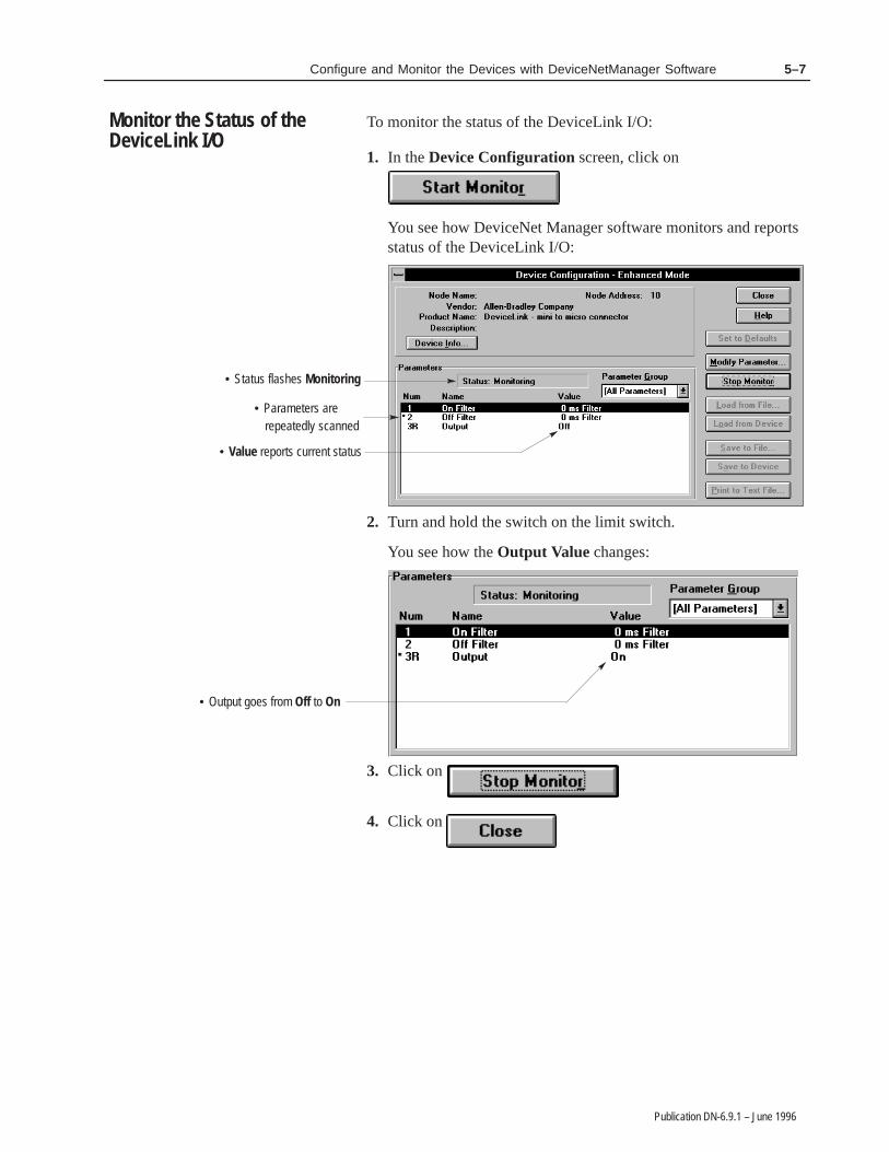
To monitor the status of the DeviceLink I/O:
1. In the Device Configuration screen, click on
You see how DeviceNet Manager software monitors and reportsstatus of the DeviceLink I/O:
• Parameters arerepeatedly scanned
• Status flashes Monitoring
• Value reports current status
2. Turn and hold the switch on the limit switch.
You see how the Output Value changes:
• Output goes from Off to On
3. Click on
4. Click on
Monitor the Status of theDeviceLink I/O

5–8 Configure and Monitor the Devices with DeviceNetManager Software
Publication DN-6.9.1 – June 1996
Continue with DeviceNetManager software to configure the1747-SDN Scanner Module.
1. From the Network Who screen, double-click on the 1747-SDNScanner Module to open its Module Configuration screen.
You see this screen:
Specify the SLC chassisslot where the scannermodule is installed.
Note: If you are using a PLC-5chassis with a 1771-SDN scannermodule, select the rack/group/slotof the 1771-SDN Scanner Module.
2. In the Load From dialog box, click on
3. In the Module Settings dialog box, specify the SLC chassis slotwhere the scanner module is installed.
4. In the Module Settings dialog box, click on
Configure the 1747-SDNScanner Module

5–9Configure and Monitor the Devices with DeviceNetManager Software
Publication DN-6.9.1 – June 1996
You see this screen:
5. Click on
6. In the Scan List Tools dialog box, click on
You see this screen:
Note: If you are using a1771-SDN scanner module, themodule should be mapped intoBlock Transfer 62 input andoutput.
7. Click on
You see this screen:
8. Click on

5–10 Configure and Monitor the Devices with DeviceNetManager Software
Publication DN-6.9.1 – June 1996
You return to this screen:
DeviceNet Manager softwareverifies that the devices havebeen mapped.
9. Click on
You see this screen:
DeviceLink I/O Node Address 10
Photoelectric SensorNode Address 07
Note: If you are using a1771-SDN scanner module,PLC-5 data table with blocktransfer addresses will appear.
800T RediSTATIONNode Address 15
Observe how the devices’ node addresses are assigned as inputsin the data table map.
10.In the Data Map area, click on the Output radio button.
11.Click on
You return to this screen:
12.Click on

5–11Configure and Monitor the Devices with DeviceNetManager Software
Publication DN-6.9.1 – June 1996
You see that all devices are highlighted:
13.In the Save To dialog box, click on
You see this screen:
14.Click on
You see this screen:
15.Click on
Wait a few more moments for the download to complete.When the download is complete and the scanner has rebooted:
• the scanner module alternately flashes 80 and 00
Top part of module
DeviceNet
STATUSMODULE NET
ADDRESS/ERROR
Node Addressand StatusDisplay
5–12 Configure and Monitor the Devices with DeviceNetManager Software
Publication DN-6.9.1 – June 1996
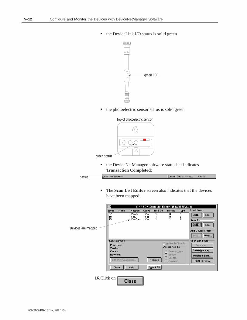
• the DeviceLink I/O status is solid green
green LED
ÎÎÎÎÎÎ
Ε the photoelectric sensor status is solid green
green status
Top of photoelectric sensor
• the DeviceNetManager software status bar indicatesTransaction Completed:
Status
• The Scan List Editor screen also indicates that the deviceshave been mapped:
Devices are mapped
16.Click on

5–13Configure and Monitor the Devices with DeviceNetManager Software
Publication DN-6.9.1 – June 1996
You see this screen:
17.Click on either or
We recommend that you save your scanner configuration files forfuture use.
In this chapter, you learned how to configure and monitor thesedevices using DeviceNetManager software:
• Series 9000 photoelectric sensor
• DeviceLink I/O
• 1747-SDN Scanner Module
Move on to Chapter 6 to learn how to use APS ladder logic withDeviceNetManager software.
Summary and What’s Next

5–14 Configure and Monitor the Devices with DeviceNetManager Software
Publication DN-6.9.1 – June 1996

Chapter 6
Publication DN-6.9.1 – June 1996
�� �� ���� ��� ��������������� ��� �� ������� ��������� ����������� ��������
This chapter describes how to use Advanced Programming Software(APS) with the DeviceNet Starter kit for DeviceNet control anddiagnostics examples:
To: See pagecreate the ladder logic program 6–2use APS with DeviceNetManager to perform DeviceNetcontrol and diagnostics examples
6–4
read the chapter summary 6–7
To complete the tasks in this chapter, you must have:
• Windows with DeviceNetManager software open
• your DeviceNet network running with an online connection
• APS installed
What this ChapterContains

6–2 Use APS with the DeviceNet Starter Kit to Perform Control and Diagnostics Examples
Publication DN-6.9.1 – June 1996
Use APS to create the following ladder logic program:
( )
MOVMOVESource
Dest
1
1
0:1.0
MOVMOVESource
Dest
M1:1.216
0
N152:0*
] [I:1
16 16
0:1
] [0:1
18
] [N152:0
7
] [N152:0
10
Create the Ladder LogicProgram

6–3Use APS with the DeviceNet Starter Kit to Perform Control and Diagnostics Examples
Publication DN-6.9.1 – June 1996
( )] [N152:0
7 17
0:1
] [I:1
17
] [N152:0
10
(L)] [I:1
33 10
0:1] [
32
I:1
(U)] [I:1
32 18
] [33
I:1/
/
0:1
[END OF FILE]
6–4 Use APS with the DeviceNet Starter Kit to Perform Control and Diagnostics Examples
Publication DN-6.9.1 – June 1996
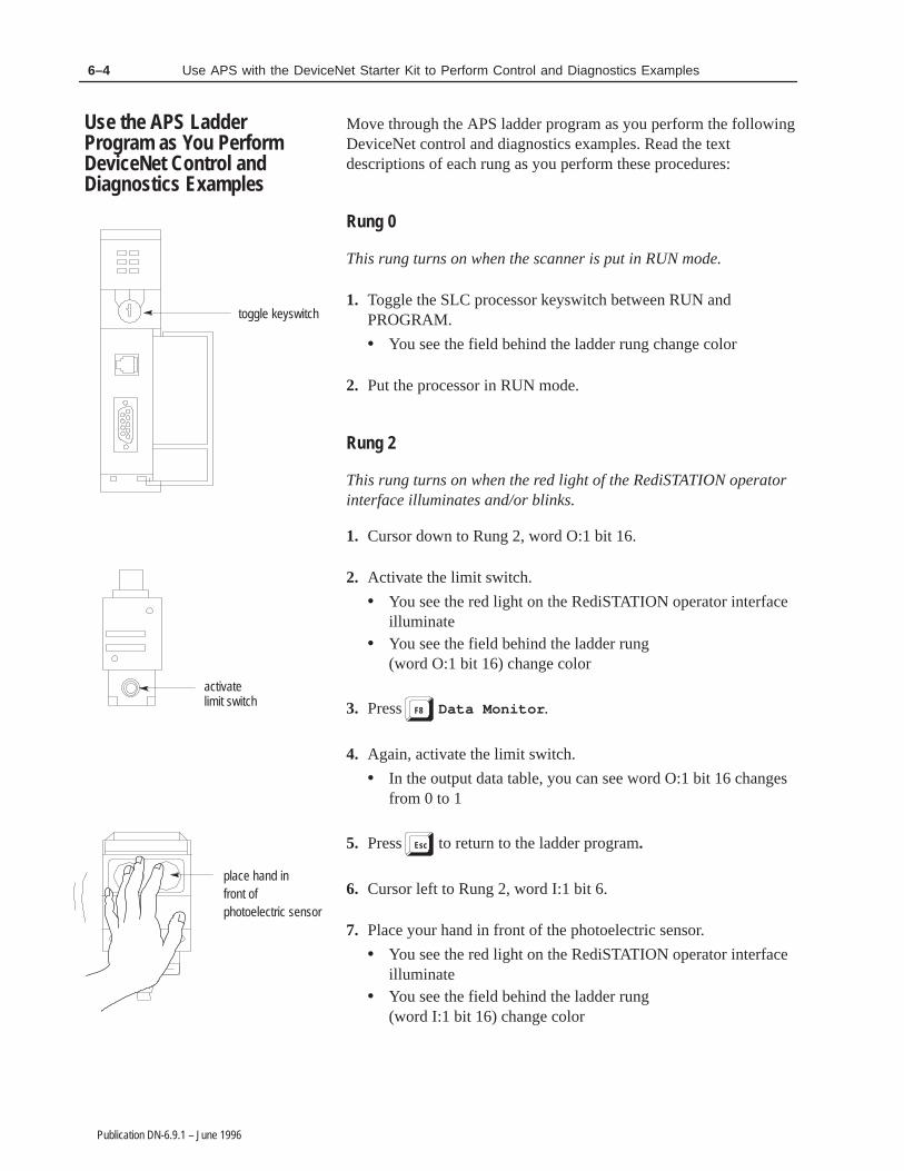
Move through the APS ladder program as you perform the followingDeviceNet control and diagnostics examples. Read the textdescriptions of each rung as you perform these procedures:
Rung 0
This rung turns on when the scanner is put in RUN mode.
1. Toggle the SLC processor keyswitch between RUN andPROGRAM.
• You see the field behind the ladder rung change color
2. Put the processor in RUN mode.
Rung 2
This rung turns on when the red light of the RediSTATION operatorinterface illuminates and/or blinks.
1. Cursor down to Rung 2, word O:1 bit 16.
2. Activate the limit switch.
• You see the red light on the RediSTATION operator interfaceilluminate
• You see the field behind the ladder rung(word O:1 bit 16) change color
3. Press F8 Data Monitor .
4. Again, activate the limit switch.
• In the output data table, you can see word O:1 bit 16 changesfrom 0 to 1
5. Press Esc to return to the ladder program.
6. Cursor left to Rung 2, word I:1 bit 6.
7. Place your hand in front of the photoelectric sensor.
• You see the red light on the RediSTATION operator interfaceilluminate
• You see the field behind the ladder rung(word I:1 bit 16) change color
toggle keyswitch
activatelimit switch
place hand infront ofphotoelectric sensor
Use the APS LadderProgram as You PerformDeviceNet Control andDiagnostics Examples

6–5Use APS with the DeviceNet Starter Kit to Perform Control and Diagnostics Examples
Publication DN-6.9.1 – June 1996
8. Press F8 Data Monitor .
9. Again, place your hand in front of the photoelectric sensor.
• In the input data table, you can see word I:1 bit 16 changesfrom 0 to 1
10.Press Esc to return to the ladder program.
Rung 3
This rung turns on when the DeviceLink I/O and the photoelectricsensor are pulled off of the DeviceNet network, or when thephotoelectric sensor is out of margin.
1. Cursor down to Rung 3, word O:1 bit 17.
2. Pull the DeviceLink I/O and the photoelectric sensor off of theDeviceNet network.
• You see the red light illuminate and flash• You see the fields behind the ladder rungs
(word O:1 bit 17) and (word N:152 bit 7) change color
3. Press F8 Data Monitor .
4. Press F1 Change Radix .
5. Press F1 Binary Data .
• In the integer data table, you can see words 6 and 9 changefrom 0 to 1
6. Press Esc to return to the ladder program.
7. Cursor down to word I:1 bit 17.
8. Put your hand over the photoelectric sensor and slowly pull yourhand away (out of margin) from the photoelectric sensor.
• You see the 800T RediSTATION red light go out• You see the photoelectric sensor indicators go out• You see the field behind the ladder rung
(word I:1 bit 17) change color
place hand infront ofphotoelectric sensor
ÎÎÎÎ
ÎÎÎÎ
ÎÎ
ÎÎÎÎ
ÎÎ
ÎÎ
disconnectDeviceLinkI/O
disconnectphotoelectricsensor
ÎÎ
ÎÎ
pull hand away fromfront of photoelectricsensor

6–6 Use APS with the DeviceNet Starter Kit to Perform Control and Diagnostics Examples
Publication DN-6.9.1 – June 1996
9. Press F8 Data Monitor .
10.Again, place your hand in front of the photoelectric sensor.
• In the input data table, you can see word I:1 bit 17 changesfrom 0 to 1
11.Again, slowly pull your hand away (out of margin) from the frontof the photoelectric sensor.
• In the input data table, you can see word I:1 bit 17 changesback from 1 to 0
Rung 4
This rung turns on when the red or green buttons on theRediSTATION operator interface are pushed.
1. Cursor to Rung 4, word I:1 bit 33.
2. Push the green button on the 800T RediSTATION operatorinterface.
• You see the red light illuminate• You see the field behind the ladder rung
(word I:1 bit 33) change color
3. Press F8 Data Monitor .
• In the input data table, you can see word I:1 bit 33 changesfrom 0 to 1 each time you push the green button
4. Cursor down to word I:1 bit 32.
5. Push the red button on the 800T RediSTATION operatorinterface.
• You see the red light go out• You see the field behind the ladder rung (word I:1 bit 32)
change color
6. Press F8 Data Monitor .
• In the input data table, you can see word I:1 bit 32 changesfrom 0 to 1 each time you push the red button
7. Press Esc to return to the ladder program.
1. Press F3 to exit APS.
pull hand away fromfront of photoelectricsensor
push green buttonon 800T RediSTATIONoperator interface
push red buttonon 800T RediSTATIONoperator interface

6–7Use APS with the DeviceNet Starter Kit to Perform Control and Diagnostics Examples
Publication DN-6.9.1 – June 1996
In this chapter, you learned how to use APS software with DeviceNetstarter kit to perform control and diagnostics:
• create the ladder logic program
• use APS with DeviceNetManager software to perform controland diagnostics examples
You are done performing the tasks in this user manual. For moreinformation on A-B DeviceNet products, call your local distributoror sales office.
Please remember to complete the survey on the enclosed floppy disk.
Business Reply Mail
DeviceNet
Feedback disk
self-addressedreturn envelope
Summary

6–8 Use APS with the DeviceNet Starter Kit to Perform Control and Diagnostics Examples
Publication DN-6.9.1 – June 1996

Publication DN-6.9.1 – June 1996
Numbers
1747-SDN scanner module. See scannermodule
1770-KFDconnecting, 3–2node address, 3–7
1770-KFD interface module, applyingpower, 3–5
800T RediSTATIONconfiguring, 4–2connecting, 4–3DIP switches, 4–2node commissioning, 4–2
A
Advanced Programming Software. SeeAPS
Allen–BradleyDeviceNet products, 7–2network architecture, 7–3related publications, 7–6support services, 7–6
Allen-Bradley, DeviceNet features andbenefits, 7–5
amperage rating, cabling, 3–4
applying, system power, 3–5
applying power1770-KFD, 3–5personal computer, 3–5power supply, 3–5SLC 500 chassis, 3–5
APSdownloading ladder logic, 6–7ladder program, 6–8required, 1–2, 1–3using with starter kit, 6–1
B
baud rate, 800T RediSTATION, 4–2
C
cable system, grounding location, 3–5
cabling, amperage rating, 3–4
checking diagnostics. See diagnostics
configuring800T RediSTATION, 4–2DeviceLink I/O, 5–5scanner module, 5–8Series 9000 Photoelectric Sensor, 5–1
connecting1747-SDN scanner module, 3–31770-KFD, 3–2800T RediSTATION, 4–3DeviceLink I/O, 4–9drop lines, 2–3limit switch, 4–9personal computer, 3–2physical media, 2–1power supply, 3–4Series 9000 Photoelectric Sensor, 4–5trunkline, 2–2
connection, online, 3–6
control and diagnostics examples, 6–8
copying files, 6–1
D
DeviceLink I/Oconfiguring, 5–5connecting, 4–9indicator, 4–9node address, 4–10node commissioning, 4–10
DeviceNetAllen-Bradley features and benefits,
7–2Allen-Bradley system overview, 7–1features and benefits, 1–1network definition, 1–1network grounding, 3–5related publications, 7–6
DeviceNet cable system, grounding, 3–5
�����

IndexI–2
Publication DN-6.9.1 – June 1996
DeviceNetManagernetwork who, 3–9setting up online connection, 3–6
diagnosticsDeviceNet examples, 6–8scanner module, 3–6
DIP switches, 800T RediSTATION, 4–2
documentation, related, 7–6
downloading, ladder logic, 6–7
downloading scan list, 6–1
drop lines, connecting, 2–3
F
floppy disk, copying files, 6–1
G
ground location, 3–5
grounding, DeviceNet network, 3–5
H
hardware, 1–2
L
ladder logic, downloading, 6–7
limit switch, connecting, 4–9
M
module. See scanner module
monitoring statusDeviceLink I/O, 5–7Series 9000 Photoelectric Sensor, 5–4
N
network grounding, 3–5
network who, performing, 3–9
node address1770-KFD, 3–7800T RediSTATION, 4–2DeviceLink I/O, 4–10Series 9000 Photoelectric Sensor, 4–6
node commissioning800T RediSTATION, 4–2DeviceLink I/O, 4–10Series 9000 Photoelectric Sensor, 4–6
O
online connectionin DeviceNetManager, 3–6setting up, 3–1
ouput fault state, 800T RediSTATION,4–2
ouput flash rate, 800T RediSTATION, 4–2
P
personal computerapplying power, 3–5connecting, 3–2required, 1–3
physical media, connecting, 2–1
power supplyapplying power, 3–5connecting, 3–4required, 1–3
processorscompatible, 1–2required, 1–2
publications, related, 7–6
R
requirementshardware, 1–2software, 1–2
rung descriptions, 6–8

Index I–3
Publication DN-6.9.1 – June 1996
S
scan list, downloading, 6–1
scanner moduleconfiguring, 5–8connecting, 3–3diagnostics, 3–6downloading scan list, 6–1
Series 9000 Photoelectric Sensorconfiguring, 5–1connecting, 4–5indicators, 4–5, 5–2monitoring status, 5–4node address, 4–6node commissioning, 4–6operating modes, 5–2
setting DIP switches, 800T RediSTATION,4–2
setting up, online connection, 3–1
SLC 500, downloading ladder logic, 6–7
SLC 500 chassis, applying power, 3–5
SLC 500 processor, required, 1–3
software, 1–2
starter kit, 1–3components
included, 1–3user–provided, 1–3
control and diagnostics examples, 6–8floppy disk, copying files, 6–1procedures, 1–4
system power, applying, 3–5
T
tool, required, 1–3
trunkline, connecting, 2–2

IndexI–4
Publication DN-6.9.1 – June 1996

Publication DN-6.9.1 – June 1996 PN 955122-83Copyright 1996 Allen-Bradley Company, Inc. Printed in USA
Allen-Bradley, a Rockwell Automation Business, has been helping its customers improveproductivity and quality for more than 90 years. We design, manufacture and support a broadrange of automation products worldwide. They include logic processors, power and motioncontrol devices, operator interfaces, sensors and a variety of software. Rockwell is one of theworld’s leading technology companies.
Worldwide representation.
Argentina • Australia • Austria • Bahrain • Belgium • Brazil • Bulgaria • Canada • Chile • China, PRC • Colombia • Costa Rica • Croatia • Cyprus • Czech Republic •Denmark • Ecuador • Egypt • El Salvador • Finland • France • Germany • Greece • Guatemala • Honduras • Hong Kong • Hungary • Iceland • India • Indonesia • Ireland • Israel • Italy • Jamaica • Japan • Jordan • Korea • Kuwait • Lebanon • Malaysia • Mexico • Netherlands • New Zealand • Norway • Pakistan • Peru •Philippines • Poland • Portugal • Puerto Rico • Qatar • Romania • Russia–CIS • Saudi Arabia • Singapore • Slovakia • Slovenia • South Africa, Republic • Spain •Sweden • Switzerland • Taiwan • Thailand • Turkey • United Arab Emirates • United Kingdom • United States • Uruguay • Venezuela • Yugoslavia
Allen-Bradley Headquarters, 1201 South Second Street, Milwaukee, WI 53204 USA, Tel: (1) 414 382-2000 Fax: (1) 414 382-4444


