

AMP8-1203
AM SERIES PULSE BOILERTROUBLESHOOTING GUIDEFOR CERTIFIED CONTRACTORS ONLY
®
5211 CREEKBANK ROADMISSISSAUGA, ONTARIO L4W 1R3 CANADA(905) 625-2991 • FAX (905) 625-6610
260 NORTH ELM STREETWESTFIELD, MA 01085(413) 568-9571 • FAX (413) 568-9613

2
TABLE OF CONTENTS
SECTION 1: OPERATION
Boiler Operating Lights - Location and function ..................................................................................................3Sequence of Operation (with lights) ...................................................................................................................3Wiring Diagrams (AM-100/-150/-300) ................................................................................................................ 5Lighting and Operating Instructions ................................................................................................................... 8
SECTION 2: TROUBLE SHOOTING
Preliminary Operational Check ...........................................................................................................................9
- Boiler is not running:Condition GC-4A Light Red Light Amber Light
A Off Off Off ....................................9B Off Off On ..................................10C Off On ...................................................................11D On ...................................................................................................12E Blinking ...............................................................................................13
- Boiler is running:Condition 1. Boiler ignites: runs for 8 seconds then shuts off .......................................................15Condition 2. Boiler attempts ignition (8 seconds) - shuts off with a “cough” or no ignition ............16Condition 3. Boiler is “short cycling” ..............................................................................................19Condition 4. Boiler and condensate water leaks ...........................................................................22Condition 5. Boiler noise (control and adjustment) .......................................................................24
a) Prolonged stutter on start-up .......................................................................................25b) Combustion/operating noise ........................................................................................26c) Vibration noise .............................................................................................................27d) Objectionable exhaust noise ........................................................................................27e) Objectionable (localized) ..............................................................................................28
SECTION 3: SERVICING/REPAIR PROCEDURES
Service Tools List .............................................................................................................................................29Fan Pressure Check .........................................................................................................................................29Gas Supply Pressure Check ............................................................................................................................29Gas Input Rate Check (Metered and Differential Methods) ..............................................................................30Adjusting Input Rate .........................................................................................................................................30Flue Box Adaptor Repair (AM-300) ..................................................................................................................30Fan Inlet Gasket Replacement (AM-300) .........................................................................................................31Air Inlet Orifice Repair (AM-300) ......................................................................................................................31Igntion Wire Check ...........................................................................................................................................31Wire Harness Assembly Replacement (AM-100 and 150) ...............................................................................31Exhaust Cushion Chamber (ECC) and/or “O” Ring Replacement (AM-100 and 150) ......................................33Disassembling AM-300 Boiler ......................................................................................................................... 33Leak Check (AM-300) .......................................................................................................................................35
-Reassembly AM-300 Boiler ......................................................................................................................35-Reposition Boiler in it's location (AM-300) ................................................................................................36
Heat Exchanger Replacement (AM-100 and 150) ............................................................................................37Boiler Reassembly (AM-100 and 150) ..............................................................................................................37Quick-Check Trouble Shooting Guide – GC-4A ...............................................................................................39
SECTION 4: REPLACEMENT PARTS LIST
Part Identification/Figs. 9 thru 12 (AM-100 / -150 / -300) .................................................................................40

3
SECTION 1: OPERATION
AMBER Part of 115V ON-OFF rocker switchLIGHT (SW1). Side of electric box (AM-100 and
AM-150). Front top of boiler (AM-300). Litwhen switch is on.
RED Top of electric box (AM-100 and AM-150).LIGHT Front top of boiler (AM-300). Lit when
all operational controls are calling for heatand 24V is supplied to the GC-4A ignitioncontrol.
GREEN Top of electric box (AM-100 and 150).LIGHT Front top of boiler (AM-300). Lit when
gas valve is energized (24V).
BOILER OPERATING LIGHTS
GC-4A On GC-4A ignition control - visible thru aLIGHT cutout in control cover near the 6-pin
Molex connector. OFF when no 24V tocontrol (no call for heat). Lit when boiler isrunning, GC-4A is in ignition sequence or on“hold” - refer to operating sequence.“Blinking” when GC-4A is in “lockout” or inthe middle of a retrial period.
LAMP Red and green bulbs can be checked withCHECK Volt/ohm meter: disconnect the lamp from
the circuit and check across the leads forcontinuity. Replace any burned out lightsor loose wiring.
SEQUENCE OF OPERATION (WITH LIGHTS)
1. Gas On/Power On. With Rocker switch SW1 (On/Offswitch) closed (amber light is ON) 115/24Vtransformer is powered. Refer to figure 1, 2 or 3for boiler wiring diagrams.
2. Boiler thermostat calls for heat; “T-T” contacts CLOSE;and circulator relay R1 (AM-100 and AM-150 only)is energized. The circulator relay contacts(C1R1) close starting the circulator pump(AM-100/-150).
3. 24 volts is also supplied to the high limit. If thelimit (automatic reset type) is “OPEN” (Red LightOFF) due to high water temperature, the ignitioncontrol waits until limit closes. When the limit closes(Red Light ON), the GC-4A ignition control isenergized (GC-4A Light ON) and checks theposition of the Combustion Prove Switch (PS1)contacts (N.O.- NORMALLY OPEN). On AM-150,the blocked inlet switch (PS3) contacts(N.C.-NORMALLY CLOSED) are also checked. Ifthe (PS1) contacts are OPEN and the (PS3) contacts(AM-150 only) are “CLOSED”, the GC-4A controlwill begin the timed ignition sequence. If either orboth of the pressure switch contacts is in an incorrectposition, the GC-4A goes on “HOLD” (Red Light“ON”; GC-4A Light “ON”) unti switch position iscorrected.
4. With the above condition satisfied, the GC-4Acontrol will begin a timed pre-purge sequence(35-seconds); start the fan; and check the fanProve Switch (PS2) contact position. This switchcontact (N.O.), must close proving blower operationbefore any gas ignition will occur. If the Fan ProveSwitch (PS2) contacts are “CLOSED” after theinitial 35-second pre-purge, the control will continuewith an attempt for gas ignition. If the (PS2)contacts remain “OPEN” there will be no attemptfor ignition (no spark or gas valve will energize)but, the fan will continue to run. After an additional26-seconds, the control will recheck the contactson (PS2). If the contacts remain open, againthere will be no attempt for ignition and the fan willcontinue to run. The control will check the contacton switch (PS2) three more times at 26-secondintervals. If the contacts remain open, there willbe no attempt at ignition. After the fifth check ofthe contacts, the fan will remain energized for a30-second post-purge period, after which the ignitionsequence will end and the GC-4A light will begin toblink (Red Light ON) indicating “LOCKOUT”(temporary). This ignition sequence will havetaken 2 min. 45 seconds. Fifteen minutes later, thecontrol will automatically begin a second ignitionsequence attempt. If the condition remainsuncorrected the retry sequence above will berepeated up to 10 times before a 100% system-lockout occurs. See “AUTOMATIC RESTARTFEATURE” section.

4
5. The ignition sequence (8 sec. duration) is controlledby the module which provides a spark at the sparkplug & energizes the gas valve (Green Light “ON).The pre-purge blower continues to operate duringthis period.
If ignition occurs during the 8-second attempt, thecombustion pressure is sensed by the Prove Switch(PS1) with switch contact (R-W) closing and provingcombustion to the GC-4A control. The fan and ignitorare then shut off; the gas valve remains energized;boiler runs (Red Light ON; Green Light ON) and theGC-4A control timer circuits are reset. Fan ProveSwitch (PS2) senses the fan shutdown and (PS2)contacts open. Boiler operation will continue until“Call for Heat” is satisfied.
If ignition does not occur during the 8-second trialperiod, the spark and gas valve will be“de-energized” (Red Light ON; Green Light OFF)and the fan will continue to run. After 26-seconds, ifthe (PS2) contacts are closed, the control willinitiate a second 8-second trial for ignition (Red LightON; Green Light ON). This sequence of 26-secondsOFF, 8-seconds ON, will occur 3 more times. If,after the fifth trial for ignition, combustion is notsustained, the ignitor and gas valve will bede-energized and the fan will continue for a30-second post-purge, after which it will shut off.This ignition sequence will have taken 3 min.30 sec. (Red Light ON; Green Light OFF; GC-4A lightblinking). The GC-4 control is on “TemporaryLockout”. Fifteen minutes after completing thisignition sequence, the control will automaticallyinitiate a second (5-trial) ignition sequence. See“Automatic Restart Feature” section for additionalsequencing details.
AUTOMATIC RESTART FEATURE: The GC-4A ignitioncontrol is equipped with an automatic reset feature. Ifthe control completes an ignition sequence (5 attemptsfor ignition) without sustaining or proving gas ignition,the control will go into a 15-minute “TemporaryLockout” mode (GC-4A light blinking) after which thecontrol will initiate a second (5-trial) ignition sequence(GC-4A Light ON). If combustion is not sustained duringthe second ignition sequence, the control will again goon a 15-minute “Temporary Lockout”, followed byanother ignition sequence. This pattern will repeat anadditional 10 times (3 hours 45 minutes total), at whichtime the control will produce a 100% “System Lockout”(GC-4A light blinking), requiring an operatingcontrol or line switch reset. To reset the boiler duringany of the ignition sequences or from the “100%Lockout” condition, momentarily de-energize theignition control by switching the rocker switch OFF andON. This resets the module to the initial starting modeof the first ignition sequence.
HI-LIMIT OPERATION: If, during the run mode, thewater temperature exceeds the limit setting, itscontacts will open and the boiler will shut down (RedLight OFF; Green Light OFF; GC-4A Light OFF).However, relay R1 operating the circulating motor(AM-100 and AM-150) will remain energized. After thewater temperature drops below the limit set point it’scontacts close (Red Light ON) and the ignition sequenceis repeated (GC-4A Light ON). Refer to step #3.
“CALL FOR HEAT” SATISFIED: When the controlthermostat is satisfied, its contacts will open,de-energize gas valve; relay R1 (AM-100/-150) andshut the boiler off. (Red Light OFF; Green Light OFF,GC-4A Light OFF). The ignition module resets await-ing the next call for heat.

5
FIG
UR
E 1
AM
-100
SC
HE
MA
TIC
& L
AD
DE
R W
IRIN
G

6
FIG
UR
E 2
AM
-150
SC
HE
MA
TIC
& L
AD
DE
R W
IRIN
G D
IAG
RA
M

7
FIG
UR
E 3
AM
-300
SC
HE
MA
TIC
& L
AD
DE
R W
IRIN
G D
IAG
RA
M

8
LIGHTING AND OPERATING INSTRUCTIONS(Honeywell VR-8305M Gas Valve)
WARNING:If you do not follow these instructions exactly, a fire or explosion may result causing properly
damage, personal injury or loss of life.
C. Use only your hand to turn gas control knob. Neveruse tools. If the knob will not turn by hand, don't try torepair it; call a qualified service technician. Force orattempted repair may result in a fire or explosion.
D. Do not use this appliance if any part has been underwater. Immediately call a qualified technician toinspect the appliance and to replace any part ofthe control system and any gas control which hasbeen under water.
TO TURN OFF GAS TO BOILER
1. Set thermostat to lowest setting.
2. Turn off all electrical power to the appliance ifservice is to be performed.
3. Turn gas control knob clockwise to “OFF”.Do not force.
LIGHTING INSTRUCTIONS
1. STOP! Read the safety information above on thispage.
2. Set the thermostat to lowest setting.
3. Turn off all electrical power to the boiler.
4. This appliance is equipped with an ignition devicewhich automatically lights the burner. Do not try tolight the burner by hand.
5. Turn gas control knob clockwise to “OFF”.Do not force!
6. Wait (5) five minutes to clear out any gas. Then smellfor gas, including near floor. If you smell gas STOP!Follow “B” in the safety information above on thispage. If you don't smell gas, go to the next step.
7. Turn gas control knob counterclockwiseto “ON”.
8. Turn on all electrical power to boiler.
9. Set thermostat to desired setting.
10. If the appliance will not operate, follow theinstructions “TO TURN OFF GAS TO BOILER” andcall your service technician or gas supplier.
OFF
ON
GAS INLET GAS OUTLET
GAS CONTROL KNOB SHOWNIN "ON" POSITION
LIGHTING INSTRUCTIONS AM-100/150/300
A. This appliance does not have a pilot. It is equippedwith an ignition device which automatically lights theburner. Do not try to light the burner by hand.
B. BEFORE OPERATING smell all around theappliance area for gas. Be sure to smell next to thefloor because some gas is heavier than air and willsettle on the floor.
WHAT TO DO IF YOU SMELL GAS• Do not light any appliance.• Do not touch any electric switch; do not use any
phone in your building.• Immediately call your gas supplier from a neighbor's
phone. Follow the gas supplier's instructions.• If you cannot reach your gas supplier, call the fire
department

9
SECTION 2: TROUBLE SHOOTING
2. If the boiler is running, but exhibits one of thefollowing conditions, observe the operatinglight conditions and use the procedure(s) underthe appropriate heading on the referenced page(s)noted.
IF BOILER IS OPERATING (CONDITIONALLY):
REF.CONDITION DESCRIPTION PAGE
1 Boiler ignites (8 sec.)but shuts-off 15
2 Boiler cycles butwon’t light 16-19
3 Boiler “short-cycling” 19-21
4 Boiler condensatewater leaks 22-23
5 Boiler noise -control/adjustment 24-28
CONDITION A
GC-4 LIGHT OFF; RED LIGHT OFF; AMBER LIGHT OFF.
This indicates no 115V to the boiler.
POSSIBLE CAUSE VERIFICATION SOLUTION
Power Supply With a voltmeter, check for 115V. If no 115V, check circuit breaker atOn AM-100 & 150 terminals1 & 4. disconnect switch and supply wiring.On AM-300 terminals 1 & 3. Connect if necessary.
If 115V, proceed with this check.
Rocker Switch With a voltmeter, check for 115V. If no 115V, operate switch. If noOn AM-100 & 150 terminals 3 & 4. 115V, check wiring to switch.On AM-300 terminals 2 & 3. If ok replace switch.
If 115V but no amber light, proceedwith check.
Amber Light With a voltmeter, check for 115V If 115V, replace switch.across terminals 2 & 3 on RockerSwitch. If no 115V, check wiring.
CAUTION: Label all wires prior to disconnectionwhen servicing controls. Wiring errors can causeimproper and dangerous operation.Verify proper operation after servicing.
PRELIMINARY OPERATIONAL CHECKRefer to Section 3 - “SERVICING PROCEDURES” for listof service tools.
1. UPON ARRIVAL AT SERVICE CALL: First - checkthe status of the boiler operating lights. If theboiler is not running, follow the procedures underthe appropriate heading on the referenced pagesbelow.
IF BOILER IS NOT RUNNING:
GC-4A RED AMBER REF.CONDITION LIGHT LIGHT LIGHT PAGE
A OFF OFF OFF 9
B OFF OFF ON 10
C OFF ON * 11
D ON * * 12
E Blinking * * 13-14
*Lights OFF indicate burned out bulb or loose wiring.

10
CONDITION B
GC-4A LIGHT OFF, RED LIGHT OFF, AMBER LIGHT ON
Turn Rocker Switch OFF and ON. If, within 10 seconds, the GC-4A light comes ON proceed to “CONDITION “E”.Replace Red Light (if OFF). If GC- 4A light remains OFF, proceed with check.
POSSIBLE CAUSE VERIFICATION SOLUTION
Operational Control(s) Turn Rocker Switch OFF. Place a If GC-4A and/or Red Lights come ONjumper across T-T terminals. check thermostat and otherTurn Rocker Switch ON. operational controls and adjust or
replace as necessary.
If lights remain OFF, proceed withcheck.
High Limit (Keep T-T jumper in place). Turn If GC-4A and/or Red Lights come ON,Rocker Switch OFF. Jumper the high limit is set too low or defective.high limit terminals. Turn Rocker Compare supply water temperatureSwitch ON. and limit setting. If settings are
proper, replace limit.
If lights remain OFF, high limit is OK.
Transformer Rocker Switch ON. With a voltmeter, If no 24V, replace transformer.check for 24V across T-T terminalsto ground. If 24V transformer is OK, proceed
with check.
AT THIS POINT RED LIGHT SHOULD BE ON - IF NOT, REPLACE LAMP
GC-4A Ignition Control Turn Rocker Switch OFF. Disconnect If 24V, reattach connector to GC-4A.6-pin Molex connector from GC-4A. If GC-4A light remains OFF, replaceTurn Rocker switch ON. With a GC-4A (and Red lamp if OFF).voltmeter, check for 24V from pin 2(brown wire) on connector to ground. If no 24V, check wires (incl. grounds)REMOVE ANY JUMPERS USED and wire connections until 24VFOR TEST. is established. If necessary, replace
wire harness.
NOTE: Non-resistive spark plugs (i.e. - Champion WR-18, etc.) must never be used in combination with a GC-4ignition module. Use only approved, resistance spark plugs (Champion FI-21503). High-voltage ignitionwiring must never contact remaining boiler wiring.

11
CONDITION C
GC-4A LIGHT OFF, RED LIGHT ON
Turn Rocker Switch OFF and ON. If, within 10 seconds, the GC-4A light come ON, proceed to CONDITION “E”.
If after the toggle switch is turned “OFF” and “ON”:
- GC-4A light remains “OFF”.
- Red light is “ON” but there is no “Prepurge Cycle” or blower operation initiated (unit is in standby mode).
- Green light “ON” immediately - but no gas flows to unit. The ignition module has lost ground continuitybetween the module and ground. Replace terminal connection on the end of ground wire (green)leaving the module.
If GC-4A light remains OFF, proceed with this check.
POSSIBLE CAUSE VERIFICATION SOLUTION
Wiring Check if green ground wire from If screw is loose, secure screw. IfGC-4A is securely fastened to the wires are not on a common screwground screw. Also check rewire the grounds.transformer ground.
If GC-4A light remains OFF, proceedwith check.
GC-4A Ignition Control Turn Rocker Switch OFF. If 24V, reattach connector to GC-4A.Remove 6-pin Molex connector from If GC-4A light remains OFF after 10GC-4A. Turn Rocker Switch ON. seconds replace GC-4A.With a voltmeter, check for 24V frompin 2 (brown wire) on connector to If no 24V, check wiring andground. connectors until 24V is established.
12
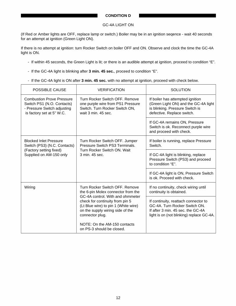
CONDITION D
GC-4A LIGHT ON
(If Red or Amber lights are OFF, replace lamp or switch.) Boiler may be in an ignition seqence - wait 40 secondsfor an attempt at ignition (Green Light ON).
If there is no attempt at ignition: turn Rocker Switch on boiler OFF and ON. Observe and clock the time the GC-4Alight is ON.
- If within 45 seconds, the Green Light is lit; or there is an audible attempt at ignition, proceed to condition “E”.
- If the GC-4A light is blinking after 3 min. 45 sec., proceed to condition “E”.
- If the GC-4A light is ON after 3 min. 45 sec. with no attempt at ignition, proceed with check below.
POSSIBLE CAUSE VERIFICATION SOLUTION
Combustion Prove Pressure Turn Rocker Switch OFF. Remove If boiler has attempted ignitionSwitch PS1 (N.O. Contacts) one purple wire from PS1 Pressure (Green Light ON) and the GC-4A light- Pressure Switch adjusting Switch. Turn Rocker Switch ON, is blinking. Pressure Switch is is factory set at 5" W.C. wait 3 min. 45 sec. defective. Replace switch.
If GC-4A remains ON, PressureSwitch is ok. Reconnect purple wireand proceed with check.
Blocked Inlet Pressure Turn Rocker Switch OFF. Jumper If boiler is running, replace PressureSwitch (PS3) (N.C. Contacts) Pressure Switch PS3 Terminals. Switch.(Factory setting fixed) Turn Rocker Switch ON. WaitSupplied on AM-150 only 3 min. 45 sec. If GC-4A light is blinking, replace
Pressure Switch (PS3) and proceedto condition “E”.
If GC-4A light is ON, Pressure Switchis ok. Proceed with check.
Wiring Turn Rocker Switch OFF. Remove If no continuity, check wiring untilthe 6-pin Molex connector from the continuity is obtained.GC-4A control. With and ohmmetercheck for continuity from pin 5 If continuity, reattach connector to(Lt Blue wire) to pin 1 (White wire) GC-4A. Turn Rocker Switch ON.on the supply wiring side of the If after 3 min. 45 sec. the GC-4Aconnector plug. light is on (not blinking) replace GC-4A.
NOTE: On the AM-150 contactson PS-3 should be closed.

13
CONDITION E
GC-4 LIGHT BLINKING
Turn the Rocker Switch OFF and ON. Observe GC-4 light and clock ON time before it begins to blink.
If Red or Amber Lights OFF, replace lamp or switch.
If the boiler starts and runs, a temporary problem may have corrected itself, (I.E., low gas pressure or a blockageof the inlet, etc). However, there may also be a slow draining condensate or a partially blocked exhaust, seeBlocked Exhaust under “CONDITION #2B”. Stop and start the boiler a number of times to assure normaloperation has been restored.
If boiler does not ignite or ignition is rough - see “CONDITION 2.”
If GC-4A light is ON 3 min, 30 sec., then starts blinking and boiler attempted ignition - proceed to “CONDITION 2”.
If GC-4A light is ON 3 min, 30 sec., then starts blinking and if boiler “coughs” or does not attempt ignition, pro-ceed to “CONDITION 2”.
If GC-4A light is ON 2 min, 45 sec., then begins to blink, measure fan pressure (see “PROCEDURES” section)and use one of the two procedures below.
MODEL NO. MINIMUM FAN PRESSURE (PS2)AM-100/-150 +1.4" W.C.
AM-300 +0.8" W.C.
1. If measured fan pressure exceeds the minimum for fan prove switch (PS2) operation.
POSSIBLE CAUSE VERIFICATION SOLUTION
Wiring Turn Rocker Switch OFF. Remove If no continuity, check wire andthe 6-pin Molex connector from the connectors until continuity isthe GC-4A. (Keep Fan Switch (PS2) obtained - reconnect Molex to GC-4Ajumper in place). With an Ohm- and run Fan Prove Switch check.meter check for continuity acrosspin-4 (grey) and 5 (lt.blue). If continuity but, condition above
exists-replace GC-4A.
Fan Prove Switch (PS2) **Turn Rocker Switch OFF. Turn If boiler starts, (PS2) pressure(N.O.) contacts Rocker Switch ON. Jumper pressure switch is defective - replace it.(Factory Fixed Setting) switch (PS2) contacts.
If the GC-4A light begins to blink after2 min. 45 sec., (PS2) switch is ok.Proceed with check.
If the boiler attempts to start and theGC-4A light blinks after 3 min.30 sec.,(PS2) switch is defective - replace it.
** NOTE: Fan must be operating before placing jumper across swith PS2. Always remove jumper before resettingboiler.

14
CONDITION “E” continued…
2. If measured fan pressure is at or below the minimum for Fan Prove Switch (PS2) operation.
POSSIBLE CAUSE VERIFICATION SOLUTION
Fan Motor Turn Rocker Switch and Gas Valve If you read 115V, proceed withtop knob OFF. Remove air cushion verification.cover. (On AM-100 & -150 lift fanassembly out of boiler and check If no voltage, check for open circuitmotor is securely fastened to the (see below).mounting plate). Disconnect the fanmotor wire leads from the boilerwiring at quick connects provided.Turn the Rocker Switch ON. With avoltmeter, check for 115V across thesupply leads from the boiler.
Turn Rocker Switch OFF. Reconnect If the motor runs, proceed with check.fan leads to motor. (For AM-100 &-150, place fan assembly on ledge If motor does not run, replace motorof air cushion chamber). Turn fan assembly.Rocker Switch ON.
AM-300 Blower Wheel - Turn Rocker Switch OFF. Remove If loose, secure blower wheelObstructed or loose fan from mounting studs and check properly on shaft. If obstructed
blower wheel is secure on shaft, not remove obstructions.rubbing against housing and freefrom obstruction. If ok, proceed with verification.
AM-300 Blocked Air Inlet Check for obstructions in air supply If obstructed, remove obstruction.Orifice vent terminal and piping. On AM-300
check inlet orifice located in inlet If unrestricted, proceed withadapter: see FIG. 7. verification.
AM-100 and 150 Check that impeller is firmly secured If broken replace impeller and/orBroken Impeller to motor shaft. assembly.
Air Inlet Vent and Lines Check air inlet terminal for blockage If obstructed - clear vent inlet.from freezing or debris.
If clear, proceed with vent line check.Check vent lines for sagging lowspots which can act as water If sagging is observed, supporttrap and reduce the air supply. pipe to remove “traps.”
Open Fan Circuit Remove the three conductor Molex If no continuity, replace GC-4GC-4A Control Checkout connector (with red and black wires) ignition control following instructions
from GC-4 ignition control. packaged with replacement.
CAUTION: 115 VAC supply. Turn If continuity is ok - check wiring.Rocker Switch OFF and then ON.Within 30 sec. check for continuityacross the two outer Molex connectorsockets on the ignition control(Term. 1 & 3).

15
CONDITION “E” continued …
POSSIBLE CAUSE VERIFICATION SOLUTION
Wiring to GC-4A (115V) Turn Rocker Switch OFF. With an If no continuity on any wire, replaceohmmeter, check continuity of red & or repair as required.black wires of the 3-conductor Molexconnector. If all continuity checks ok, check if
motor wire terminals mate correctlywhen joined.
Turn gas valve top knob to “ON” aftercompleting checkout.
CONDITION #1 - BOILER IGNITES (8 SECONDS) THEN SHUTS OFF
GC-4A Light is “ON”, Red Light “ON”, Green Light “ON” (during 8 second ignition trial). After 3 min. 45 sec (5unsuccessful igntion trials) the GC- 4A light then blinks.
IF THE BOILER, WHEN IT RUNS, STOPS BEFORE THE GREEN LIGHT GOES OUT - PROCEED TO“CONDITION #3.”
POSSIBLE CAUSE VERIFICATION SOLUTION
Copper Pressure Sensing Turn Rocker Switch OFF & remove Repair or replace as necessary.Tube top from Air Cushion Chamber
(A.C.C.). (On AM-100 & -150 removeRuns from Gas Cushion fan assembly). Check tube for breaksChamber (G.C.C.) valve at the GCC valve plate & on theplate to Combustion AM-300 at the fitting on the ACCProve-Pressure Switch (PS1). wall. Check unions are tightly
connected.
Pressure Switch (PS1) If removed, replace fan assembly If boiler runs more than 9 seconds(Combustion Prove Switch) and air cushion chamber top and (with jumper in place), replace switch
turn Rocker Switch ON. (PS1).
Immediately after boiler starts, place If boiler runs 8 seconds (stops whenjumper across PS1 pressure Green Light goes OFF) with theswitch terminals (R-W). DO NOT jumper in place, proceed withPUT JUMPER ON UNTIL GAS verification.VALVE IS ENERGIZED.
CAUTION: TERMINAL VOLTAGEEXCEEDS 300 VOLTS.(Remove jumper after test).
Wiring - Purple Wires (2) Check both purple wires from (PS1) If loose, reconnect wires. RepeatFrom PS1 to GC-4A Ignition pressure switch to ignition control. Pressure Switch verification. If boilerControl Connections must be secure to runs less than 9 seconds (with
complete circuit from module. jumper in place), switch is ok.
If no loose wires, replace GC-4Aignition module following instructionspackaged with replacement.

16
CONDITION #2 - BOILER ATTEMPTS IGNITION (8 SECONDS) WITH ONLY A “COUGH” OR NO IGNITION: THEN SHUTS OFF
GC-4A Light is “ON”; Red Light “ON”; Green Light “ON”; - during each 8 sec. ignition trial (5 attempts). Unit doesnot run after 3 min. 45 sec. The GC-4 light then blinks.
NOTE: ON A START-UP, BOILER MAY LOCK OUT SEVERAL TIMES BEFORE ALL AIR IS PURGED FROMGAS LINE.
MEASURE FAN PRESSURE (SEE “PROCEDURES” SECTION) AND USE ONE OF THE THREE PROCE-DURES BELOW.
A. IF FAN PRESSURE MEASURES NORMAL: +1.5 to 1.9"W.C. for AM-100 & -150.+1.0 to 1.4"W.C. for AM-300.
POSSIBLE CAUSE VERIFICATION SOLUTION
Gas Line Valves Check that all valves in gas line, Open all gas valves in gas line.including combination gas valve,are in open position.
Incorrect Gas Supply With manometer, check gas supply Adjust gas supply pressure asPressure (should be pressure as described in necessary.between 4.5" to 7.0" W.C. “Procedures” section of this manual.for Natural Gas;11” W.C.for Propane Gas)
Combination Gas Valve Turn the Rocker Switch OFF and If no 24V & no green light, check (24V) ON. After 35 seconds,with a wiring. If intact and secure - replace
voltmeter, check for 24V across the GC-4A.gas valve terminals (MV-MV).
If read 24V & green light OFF replacegreen lamp and proceed with check.
Put manometer downstream of gas If no indication of gas flow, replacevalve. When gas valve opens gas valve.(Green Light “ON”) gas pressureshould increase. (Manometer will If gas flow is confirmed, proceedread a purge fan pressure before with check.valve opens).
Check Ignition Circuit Turn Rocker Switch & Gas Valve If spark is strong, control is ok.(GC-4 Ignition Control) top knob “OFF.” Turn Rocker Switch Reconnect ignition lead.
“On” & allow unit to purge to asequenced lockout (temporary). If no spark, check that the whiteTurn Rocker Switch “OFF” and (neutral) lead is securely connectedremove high tension ignition lead from the “NEU” spade connection onfrom ignition control. Turn Rocker ignition module to neutral side of theSwitch “ON” & after 34 sec. (purge), 24V transformer.check for spark with insulatedscrewdriver between the ignition If secure and not sparking, replacecontrol spud & ground. the GC-4 ignition control.
CAUTION: Hi-voltage Potential.

17
CONDITION #2 continued …
POSSIBLE CAUSE VERIFICATION SOLUTION
Ignition Lead Turn Rocker Switch “OFF.” Remove If no continuity or damaged lead -cover from ACC. Remove the fan then replace wire harness assembly.assembly on the AM-100 & -150. (See “Procedures” section).With an ohmmeter, check lead for Reseal “ACC” chamber opening.continuity. Visually check lead wireand boot for tears, abrasions or If continuity & lead checks“burn spots” indicating a short circuit. satisfactorily - proceed with
verification.NOTE: Hi-voltage ignition leadwiring must not contact regular If visual check is ok perform ignitionwiring on boiler. wire check (“Procedures”
section).
If ok proceed with verificaiton.
Spark Plug Turn Rocker Switch & Gas Valve If plug is ok - check gap (.100" toTop Knob “OFF”. Remove spark .125") and reassemble in boiler.
Use only resistive-type plug from combustion chamber andspark plug (Champion visually check for ceramic cracks, If plug is worn or ceramic cracked -FI-21503): Replace any carbon tracks, and wear. Attach the replace plug.non-resistive type plugs ignition lead to spark plug & place(WR-18/etc.) plug on head of boiler. Jumper Fan If plug shows carbon tracks or
Prove Switch (PS2). Turn Rocker excessive carbon deposits, cleanSwitch “ON” and observe the spark plug and proceed with check.during the ignition sequence.
Input Rate Reassemble boiler.Turn Rocker If boiler won’t run & you suspectSwitch “OFF” & Gas Valve Top Knob “overfire”; check if pressure“ON.”Turn Rocker switch “ON” regulator adjusting screw is(start boiler). bottomed out. Turn screw
counterclockwise (in 1/4 turnAfter boiler runs for at least 10 min. - intervals) to decease flow rate.check input rate according to one After each adjustment replaceof two methods described under pressure regulator cap before“Procedures” section of this turning “ON” boiler.manual. Adjust gas valve regulatoras necessary to deliver desired If boiler won’t run & you suspect input rate. “underfire”, check if adjusting screw
is topped out. Turn screw clockwiseTo adjust pressure - turn OFF in 1/4 turn intervals to increaseboiler/remove regulator cap on flow rate. After each adjustmentgas valve. Replace regulator cap replace pressure regulator cap(secure) before re-starting unit and before turning “ON” boiler.determining effects of adjustment.
“O-Ring” seal on regulator cap mustfit securely against valve whenoperating boiler. Replace old/wornO-Ring if necessary.
18
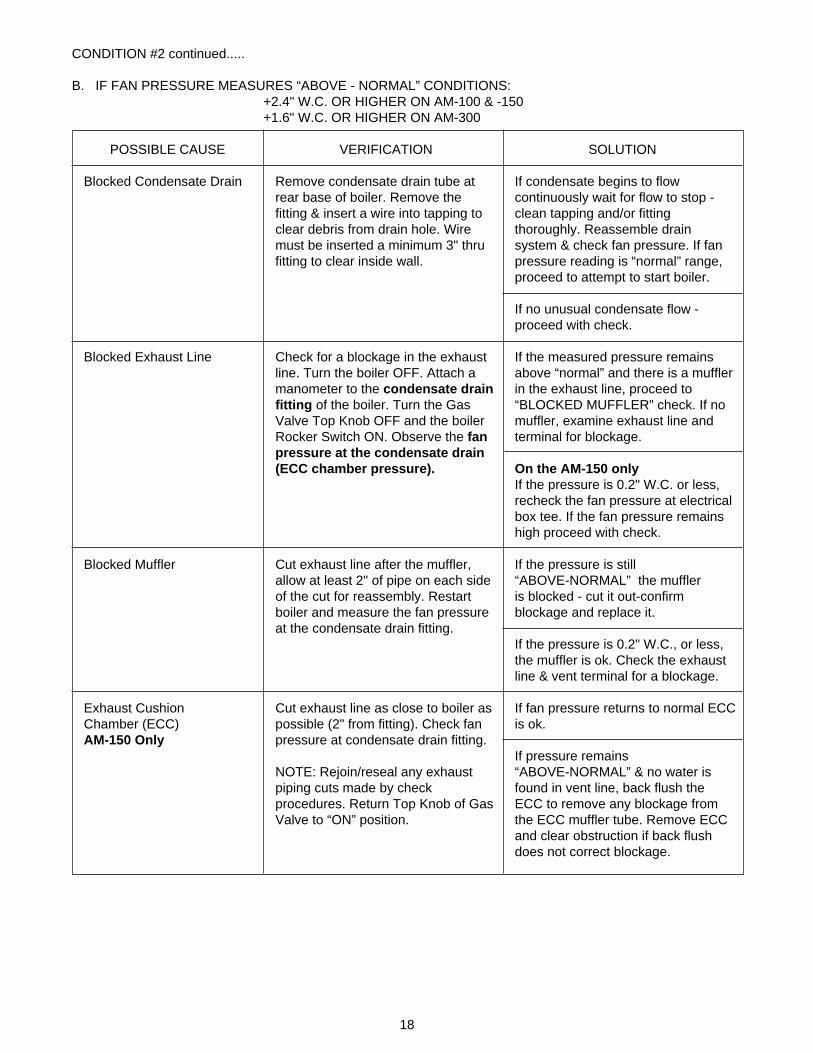
CONDITION #2 continued.....
B. IF FAN PRESSURE MEASURES “ABOVE - NORMAL” CONDITIONS:+2.4" W.C. OR HIGHER ON AM-100 & -150+1.6" W.C. OR HIGHER ON AM-300
POSSIBLE CAUSE VERIFICATION SOLUTION
Blocked Condensate Drain Remove condensate drain tube at If condensate begins to flowrear base of boiler. Remove the continuously wait for flow to stop -fitting & insert a wire into tapping to clean tapping and/or fittingclear debris from drain hole. Wire thoroughly. Reassemble drainmust be inserted a minimum 3" thru system & check fan pressure. If fanfitting to clear inside wall. pressure reading is “normal” range,
proceed to attempt to start boiler.
If no unusual condensate flow -proceed with check.
Blocked Exhaust Line Check for a blockage in the exhaust If the measured pressure remainsline. Turn the boiler OFF. Attach a above “normal” and there is a mufflermanometer to the condensate drain in the exhaust line, proceed tofitting of the boiler. Turn the Gas “BLOCKED MUFFLER” check. If noValve Top Knob OFF and the boiler muffler, examine exhaust line andRocker Switch ON. Observe the fan terminal for blockage.pressure at the condensate drain(ECC chamber pressure). On the AM-150 only
If the pressure is 0.2" W.C. or less,recheck the fan pressure at electricalbox tee. If the fan pressure remainshigh proceed with check.
Blocked Muffler Cut exhaust line after the muffler, If the pressure is stillallow at least 2" of pipe on each side “ABOVE-NORMAL” the mufflerof the cut for reassembly. Restart is blocked - cut it out-confirmboiler and measure the fan pressure blockage and replace it.at the condensate drain fitting.
If the pressure is 0.2" W.C., or less,the muffler is ok. Check the exhaustline & vent terminal for a blockage.
Exhaust Cushion Cut exhaust line as close to boiler as If fan pressure returns to normal ECCChamber (ECC) possible (2" from fitting). Check fan is ok.AM-150 Only pressure at condensate drain fitting.
If pressure remainsNOTE: Rejoin/reseal any exhaust “ABOVE-NORMAL” & no water ispiping cuts made by check found in vent line, back flush theprocedures. Return Top Knob of Gas ECC to remove any blockage fromValve to “ON” position. the ECC muffler tube. Remove ECC
and clear obstruction if back flushdoes not correct blockage.

19
CONDITION #2 continued.........
C. IF FAN PRESSURE MEASURES “BELOW-NORMAL” CONDITIONS:• LESS THAN 1.45" W.C. ON AM-100 & -150• LESS THAN 1.0" W.C. ON AM-300
POSSIBLE CAUSE VERIFICATION SOLUTION
Air Inlet Pipes/Fan Assembly Turn “OFF” Rocker Switch. Turn gas If fan pressure increases to normal(AM-100 & -150 Only) valve top knob OFF. Remove lid range, check the inlet piping, inlet
from ACC. Turn Rocker Switch “ON” muffler & inlet vent terminal forand hold fan assembly firmly in place obstruction.in its typical mounting position.Observe fan pressure (see If fan pressure remains the same,“Procedures” section - repair or replace fan assembly. If“FAN PRESSURE.”) ok - proceed with check.
Obstructed Turn Rocker Switch and Gas Valve If loose, secure blower wheelor Loose Blower Wheel top knob OFF. Remove Air Cushion properly on shaft. Remove(AM-300) Chamber cover. Remove fan from obstructions. If ok proceed with
mounting studs & check blower check.wheel is secure on shaft,not rubbingagainst housing & free fromobstruction.
Fan Assembly Hold fan assembly in typical If motor runs ok - check for inlet vent(AM-300) mounting position & turn Rocker restriction including inlet air orifice
Switch ON (gas OFF). Observe fan located in inlet adapter on AM-300.operation and direction of rotation. See FIG.7.(DO NOT LUBRICATE MOTOR).
If motor runs slowly, replaceassembly.
Fan Inlet Gasket Check for compression marks on If gasket is not sealed properly,(AM-100 & -150 only) gasket for complete seal to air inlet replace it. See “Procedure”
adapter & that gasket seals section in this manual for details.completely (360-degrees) aroundfan inlet opening.
CONDITION 3 - BOILER IS SHORT-CYCLING
Boiler ignition occurs, strong start but runs only short time (red and green lights on) and then suddenly stops. Iflights are operational, observe lights as detailed below and follow appropriate procedures.
• IF BOTH RED & GREEN LIGHTS GO OUT WHEN BOILER STOPS, BOILER IS RESPONDING TO ANOPERATIONAL CONTROL THAT IS SATISFIED. CHECK SET POINTS ON HI-LIMIT, CIRCULATOR,THERMOSTAT AND OTHER BOILER CONTROLS. ADJUST AS NECESSARY.
• IF GREEN LIGHT GOES OFF WITHIN SECONDS AFTER BOILER STOPS; RED LIGHT STAYS ON;AND BOILER DOES NOT RESTART. PROCEED WITH (3B) CHECK BELOW.
• IF GREEN LIGHT GOES OFF WITHIN SECONDS AFTER BOILER STOPS; RED LIGHT STAYS ON;BUT BOILER IMMEDIATELY RESTARTS, PROBLEM IS COMBUSTION RELATED. PROCEED WITHOPERATIONAL CHECK BELOW (3A).

20
CONDITION 3A - BOILER SHORT CYCLES BUT AUTOMATICALLY RESTARTS
POSSIBLE CAUSE VERIFICATION SOLUTION
Recirculation of Exhaust Visually check air inlet terminal(s) for If there is recirculation, temporarilyat Inlet Terminals exhaust recirculation (vapor path). extend exhaust vent. If this
eliminates problem, proceed withNOTE: On thru-the-wall installations permanent fix.the exhaust should extend aminimum 12" beyond the inlet If no recirculation proceed withterminal. trouble shooting procedures.
Recirculation of Exhaust - Turn Rocker Switch & Gas Valve top (1) If valve discs have torn edges orInternal knob to OFF. Remove lid from Air holes - replace discs.
Cushion Chamber (ACC). On (2) If foreign particles are betweenAM-100 & -150 remove the fan valve plate & valve retainingassembly. Remove the gas plate, remove them.Cushion Chamber (GCC) & check (3) If valve discs are missing, replacethe bottom of the valve plate. GCC them.valve discs must move freely and not (4) If valve discs are “wrinkled” andbind. stiff - replace them and check
condensate drain and exhaust line for partial blockage.
Check GCC gasket for crimps or If crimps, carbon trails, replacecarbon trails. gasket following instructions with
replacement.
If ok, proceed with verification.
Recirculation of Exhaust - With GCC removed, remove If O-ring has burned, hardened orInternal combustion chamber inlet (flame has decomposed sections, check(AM-300 Only) trap assembly). Check if O-ring adjoining chamber and chamber
between Combustion Chamber & inlet surfaces for obstructions whichinlet is intact. Check mating surfaces may prevent flush mating of the twoof inlet and combustion chamber. surfaces. Remove any obstructions,These must be clean and free of clean O-ring groove and replacedebris before re-assembly. O-ring. (See “Procedures” section).
If O-ring is ok proceed with trouble-shooting procedures.
Flame Trap (LP Boilers) With GCC removed, check that If any problems are evident, correct(AM-100 & -150 Only) flame trap seats properly (no or replace the flame trap. If in doubt,
movement or rocking). Corrugated replace flame trap and run boiler tostrips should be flush with flange see if problem is corrected.face (not coned) and show nosigns of “burn by” (no gaps/spaces). If ok, proceed with checkout.

21
CONDITION #3A continued …
POSSIBLE CAUSE VERIFICATION SOLUTION
Overfire Reassemble boiler. Check input to If overfired-adjust input - seeboiler using one of the prescribed “Procedures” Section. If obtainingmethods under “Procedures” section rate is difficult or starts are adverselyof the manual. Gas Valve regulator affected, check that vent line tubingcap (with O-ring gasket) and vent line (1/8"O.D. copper) from gas valvetubing (1/8" O.D. copper) must be is ok. To check: remove fromsecurely connected at gas valve regulator, connect to a manometer.terminations. Record fan pressure during purge
cycle. If no - reading, checkconnections & blow line clear.
If ok and boiler is installed 3 years ormore, consider replacing gas valveregulator.*
If “on rate” - proceed with checkout.
Condensate Traps in Check for accumulation of Eliminate potential for any low pointsExhaust Vent Piping condensate in low points of exhaust in exhaust piping or provide auxiliary(Boiler has a one to two vent pipe. condensate traps. Correct any short-second beat after starting) cycling conditions which prevent
normal drainage.
*Circa 1994 boiler and later are equipped with gas valves which do not have replaceable regulators. These 5-yrtune up kits do not include a replacement regulator.
CONDITION 3B - BOILER SHORT CYCLES BUT DOES NOT RESTART
• IF GREEN LIGHT GOES OFF BOILER STOPS & RED LIGHT STAYS ON BUTBOILER DOES NOT RESTART.
POSSIBLE CAUSE VERIFICATION SOLUTION
Wire Connections Check for loose wire/connections at Tighten or correct loose connections.Ignition Control Module (includingground terminals); Gas Valve; Check that GC-4A ground wire sharesHi-limit & Combustion Prove common ground with transformerPressure Switch (PS1). secondary.
Isolate and secure ignition cablefrom contact with all other 24V and115V wiring.
NOTE: Use only approved resistivespark plugs w/GC-4A control.
Pressure Switch (PS1) Turn Rocker Switch & Gas Valve top If boiler stops short cycling, - replace(Combustion Prove Switch) knob to ON. Immediately after boiler pressure switch.
starts, place jumper across PS1Pressure Switch terminal (R-W). DO If boiler continues to short cycle -NOT PUT JUMPER ON UNTIL GAS replace ignition control moduleVALVE IS ENERGIZED. following instructions packaged with
replacement. Check and verifyCAUTION: TERMINAL VOLTAGE proper module grounding.EXCEEDS 300 VOLTS. (Removejumper after test).
22
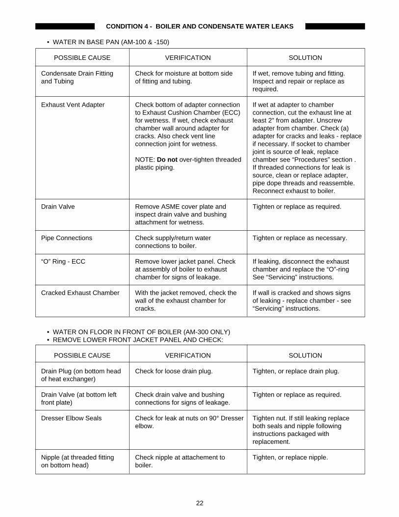
CONDITION 4 - BOILER AND CONDENSATE WATER LEAKS
• WATER IN BASE PAN (AM-100 & -150)
POSSIBLE CAUSE VERIFICATION SOLUTION
Condensate Drain Fitting Check for moisture at bottom side If wet, remove tubing and fitting.and Tubing of fitting and tubing. Inspect and repair or replace as
required.
Exhaust Vent Adapter Check bottom of adapter connection If wet at adapter to chamberto Exhaust Cushion Chamber (ECC) connection, cut the exhaust line atfor wetness. If wet, check exhaust least 2" from adapter. Unscrewchamber wall around adapter for adapter from chamber. Check (a)cracks. Also check vent line adapter for cracks and leaks - replaceconnection joint for wetness. if necessary. If socket to chamber
joint is source of leak, replaceNOTE: Do not over-tighten threaded chamber see “Procedures” section .plastic piping. If threaded connections for leak is
source, clean or replace adapter,pipe dope threads and reassemble.Reconnect exhaust to boiler.
Drain Valve Remove ASME cover plate and Tighten or replace as required.inspect drain valve and bushingattachment for wetness.
Pipe Connections Check supply/return water Tighten or replace as necessary.connections to boiler.
“O” Ring - ECC Remove lower jacket panel. Check If leaking, disconnect the exhaustat assembly of boiler to exhaust chamber and replace the “O”-ringchamber for signs of leakage. See “Servicing” instructions.
Cracked Exhaust Chamber With the jacket removed, check the If wall is cracked and shows signswall of the exhaust chamber for of leaking - replace chamber - seecracks. “Servicing” instructions.
• WATER ON FLOOR IN FRONT OF BOILER (AM-300 ONLY)• REMOVE LOWER FRONT JACKET PANEL AND CHECK:
POSSIBLE CAUSE VERIFICATION SOLUTION
Drain Plug (on bottom head Check for loose drain plug. Tighten, or replace drain plug.of heat exchanger)
Drain Valve (at bottom left Check drain valve and bushing Tighten or replace as required.front plate) connections for signs of leakage.
Dresser Elbow Seals Check for leak at nuts on 90° Dresser Tighten nut. If still leaking replaceelbow. both seals and nipple following
instructions packaged withreplacement.
Nipple (at threaded fitting Check nipple at attachement to Tighten, or replace nipple.on bottom head) boiler.

23
CONDITION #4 continued …
• WATER ON FLOOR AT REAR OF BOILER (AM-300)
POSSIBLE CAUSE VERIFICATION SOLUTION
Condensate Fitting & Tubing Check condensate fitting & tubing. Tighten,or replace fitting/tubing.
Flue Box Gasket Check for moisture at flue box If wet, replace gasket followingattachment to rear plate on packaged instructions.economizer.
Flue Box Adapter Check for moisture at flue pipe If joint/vent pipe has leak, repair it.connection to flue box. If wet, checkfor condensate drainage above flue If leaking at flue box adapter,box. see “Procedures” section of this
manual under “Repairing Flue BoxAdaptor”.
Flue Box Check flue box for cracks & holes. If crack/holes, replace flue box(with or without adapter) followinginstructions pack - packaged withreplacement.
Pipe Attachments Check Supply/Return water,Relief Tighten or replace components asValve and Hi-limit connections. necessary. Relief valve discharge
should be piped to floor drain.
• CONDENSATE DRAINS AFTER BOILER SHUTS OFF
NOTE: It is not unusual for condensate to drain from boiler for several minutes (maximum of 15 minutes), afterboiler shuts down. Amount of condensate depends chiefly on boiler operating conditions, however, flue configura-tion and ambient conditions, are all factors in the amount of condensate accumulated in the flue box and thedrainage rate from exhaust piping systems.
POSSIBLE CAUSE VERIFICATION SOLUTION
Boiler Leak (1) Pressurize boiler, bank of boilers If pressure remains same & flow or system as determined by from condensate drain ceases, installation, to its normal boiler is ok. operating pressure.(2) Turn power OFF & close return If pressure drops & flow from & supply valves of boiler/banks condensate drain continues, there of boilers; or shut-off system is boiler leak. Disassemble boiler, automatic & manual fill valves. per “Servicing” instructions described (3) Observe boiler or system in this manual, pinpoint leak and pressure during a 15-20 minute replace leaking components. OFF period.

24
CONDITION 5 - BOILER NOISE - CONTROL AND ADJUSTMENTS
A certain amount of operational noise is to be considered “NORMAL” when operating a PULSE BOILER. Most“objectionable” noise occurs on start-up and is correctable by the procedures outlined in this section.
NORMAL OPERATION:
START-UP CHARACTERISTICS:
• Typically smooth/rapid ignition during initial ignition period, (1-2 seconds to establish operation).
• Start-up may include occasional “Stutter” (or “Puff” or “Pulse”) but, boiler quickly adjusts to abalanced steady-state operation.
STEADY-STATE OPERATION:
• Produces an audible but steady “Hum” (like a muted motor sound) when listening closely atexhaust terminal.
“OBJECTIONABLE” NOISE:
START-UP CHARACTERISTICS:
• Typically requires adjustment or changes to the boiler installation. If uncorrected may causeunusual wear of boiler parts which also affect noise.
• Usually caused by “Delay” or “Dislocation” (fuel rich/fuel poor) of sustained ignition during start-up.Ignition may correct itself or system may “Snuff-out” and retry (unsuccessful ignition). This is oftencharacterized by “Thud(s)” / ”Thump(s) / ”Pop(s) / ”Crack(s)” depending on severity of condition.
STEADY-STATE OPERATION:
• Sound/frequency levels produced at exhaust terminals or transmitted to structure (via piping, etc.),are minimized by conforming to installation criteria/proper boiler adjustment/and trying exhaustchanges.

25
CONDITION 5a - PROLONGED “STUTTER” ON START-UP (AM-300)
• An occasional stutter when starting can be expected (i.e. - cold water/initial start-up.)
POSSIBLE CAUSE VERIFICATION SOLUTION
Incorrect Gas Supply Check Gas Supply Pressure and Adjust Gas Supply Pressure asPressure (should be gas input rate as outlined under necessary. A supply regulatorbetween 4.5" to 7.0" W.C.) “Procedures” section of this manual. may be required. Supply pressure to
boiler to be 4.5 - 7.0" W.C. running.Adjust input rate per procedure.
Low Fan Pressure Turn Rocker Switch & Gas Valve top If gasket not seated properly -(less than 1.0"W.C.) knob to “OFF”. Remove ACC cover. replace it. Follow “Procedures”
Remove fan from mounting studs & section in this manual.check for compression marks onfan inlet gasket for complete seal to If gasket is seated properly, proceedair inlet adapter. Gasket is to fit with check.completly (360-degrees) around faninlet opening.
Check air inlet terminal for If restricted - remove restriction.restriction.
If no restriction proceed withverification.
Loose or Restricted Air Check that air inlet orifice (inside air If air inlet orifice is loose, repair it.Inlet Orifice inlet adapter) is intact & not loose Follow “Disassembling AM-300”
or broken. Drain hole must be clear. procedure described in this manual.See “Procedures” section (Fig. 7)for detail. If air inlet orifice is broken, replace
air inlet adapter.
Check for restriction in air inlet orifice. Remove any restriction(s).
Valve Discs Remove Gas Cushion Chamber 1. If valve discs have torn edges or(GCC) & check bottom of valve holes - replace discs.plate. GCC valve discs must move 2. If foreign particles are betweenfreely and not bind. valve plate & valve retaining plate-
remove them.Reinstall boiler parts when 3. If valve discs are missing, stiff orcompleted. “wrinkled” replace them.
Long Horizontal Vent Check that all vent piping runs are Correct pitch of vent piping runs toPiping with Minimal Pitch pitched (minimum of 1/4" per foot) prevent condensate blockage of
from vent terminal back to boiler. exhaust / inlet piping.
Condensate Trapped in Check for accumulation of Eliminate low points in exhaustExhaust Vent Piping condensate in low points of piping or provide auxiliary
exhaust vent piping. condensate drain taps.(1/2" dia. max.)
Improperly Sized Vent Check that all vent piping is specified If incorrect, change vent piping.Piping Schedule 40; (not Schedule 80) and
maximum number of elbows andvent length is not exceeded.

26
CONDITION 5b - COMBUSTION / OPERATING NOISE (STEADY-STATE)
POSSIBLE CAUSE VERIFICATION SOLUTION
Boiler Overfired Check gas supply pressure and Adjust supply pressure and/or input gas input rate as described in rate as necessary. If boiler is in“Procedures” section of this operation more than 5 years - it ismanual. recommended to install a tune-up kit.
“ACC” to Boiler Gasket Place your ear against the boiler If sound level is not uniform, a gasketjacket approx. 14" from top. Circle leak may be suspect. With the lidthe boiler. Check for uniform sound removed visually check the gasketfor uniform sound level. from inside the ACC - at the
boiler/ACC seam. (Remove theinsulation from the side wall prior tovisualcheck-AM-300). If a gap isidentified, fill with silicon. See“Procedures” section if gasketreplacement is required.
Insulation between Top Remove jacket top cover & check Adjust as necessary.Jacket Access Panel & that insulation is in place.Air Cushion Chamber(A.C.C.) Lid
A.C.C. Lid & Gasket Turn Rocker Switch & gas valve top If gasket has gaps, tears, etc.,knob “OFF.” Check if lid is securely replace entire gasket. If nutsfastened. Remove “ACC” lid. Check securing lid are loose, tighten them.gasket between “ACC” & lid is intact.
Valve Discs (G.C.C.) Remove Gas Cushion Chamber 1. If valve discs have torn edges or(GCC) and inspect bottom of valve holes - replace discs.plate. [Remove fan assembly 2. If foreign particles are between(AM-100/-150 only) to get access valve plate & valve retainingto (GCC)]. Valve discs must move plate - remove them.freely & not bind. 3. If valve discs are missing;
“wrinkled” or “stiff” - replace them. Check condensate drain/exhaust lines for partial blockage.
Combustion Chamber Inlet Remove and check that inlet is flat If coned, remove inlet & carefully(Flame Trap Assy). & not coned in either direction. align corrugation edges. DO NOT(Replacement Gaskets DISTORT. (Check O-ring).required) Reassemble boiler when completed. AM-100/-150 flame trap assy. is a
replacement part.

27
CONDITION 5c - VIBRATION NOISE (IN-HOUSE) BUT, REMOTE FROM BOILER (STEADY-STATE)
POSSIBLE CAUSE VERIFICATION SOLUTION
Air Intake & Exhaust Lines Visually check that the lines are If pipes are rigidly supported or insupported with vibration isolator direct contact with the buildingsupports & the lines are isolated structure, change the supports tofrom the building structure - vibration isolators or re-route theespecially where exiting the building piping as required. See Installationor passing thru walls. Manual (AM2).
CONDITION 5d - “OBJECTIONABLE” EXHAUST NOISE (MUFFLERS INSTALLED)
CONDITION VERIFICATION SOLUTION
Exhaust Noise Add a one foot extension to the If there is a perceptable noiseWhen Boiler Runs exhaust termination (remove after reduction permanently attach the
check). Exhaust piping CPVC one foot extension you have added.(SCH-40) length should not exceedinstallation limitations. The sound you are hearing may be
the normal operating sound of theNOTE: Thru-the -wall exhaust boiler. Check with Customer Serviceterminals require a 12" extension for additional options in noiseto begin with. reduction
- Dull-“Thud” or “Pop” on Check for high gas supply pressure If inlet gas supply pressure exceeds Start-up. per “Procedures” section in this 7" W.C. install a “lock-up” style
manual (typical 4.5 - 7.0" W.C.). If supply pressure regulator as close tore-adjusted a lowside gas pressure is boiler as possible. Set this regulator
- Sharp-“Crack” on Start-up. preferred. at 4.5 to 5" W.C. delivery pressurewhen running. Recheck gas input
(AM-300) NOTE: If boiler is more than rate per procedure.5 yrs old - consider tune-up kitinstallation. If problem persists call Customer
Service for a “Hard Start” kit.

28
CONDITION 5e - OBJECTIONABLE (LOCALIZED) NOISE - STEADY-STATE
POSSIBLE CAUSE VERIFICATION SOLUTION
Exhaust Line Leak Check exhaust vent line, joints & Repair or replace as necessary withconnections to boiler. “SCH-40” CPVC parts.
“O” Ring between Boiler & With the boiler running for 5-minutes; If a leak is suspect, remove lowerExhaust Cushion Chamber feel around the jacket about 3" jacket panel. Restart boiler and(ECC) below the lower jacket panel seam locate exhaust leak.
for “hot spots”. This is an indication(AM-100/-150) of internal gasket leakage. If confirmed - replace “O” ring. See
replacement instructions under“Procedures” section. Replacejacket panel.
Gasket between Boiler & With the boiler running for 5-minutes, If noise/hot spot is suspect, removeEconomizer check boiler sides/rear about 15" jacket & insulation. Check gasket for
from jacket bottom for noise or hot leaks. If leaking, replace gasket(AM-300) spots (as opposed to other areas). following instructions packaged
with replacement.
NOTE: Remove the top access panel. If noise/hot spot is not confirmed,If there is moisture on top insulation proceed with verification.or on top of A.C.C., a gasket leak isprobable.
To check for noise at boiler front,remove lower front panel.
Flue Box-To-Economizer Check if gasket is deteriorated or If deteriorated or blown out, replaceGasket blown out. gasket following instructions(AM-300) packaged with replacement.

29
SECTION 3: SERVICING & REPAIR PROCEDURES
SERVICING TOOLS LIST:• Volt/OHM/Continuity Meter• 15/16" Deep Socket• Breaker Bar (Spark Plug Removal).• 48" U-Tube Manometer (not magnahelic or dial type)• 3/16" I.D. Manometer Tubing• 3/16" O.D. x 5" long - Copper Tubing• Zinc Rich - Cold Galv. compound• 3/16" Hose Barb - Tee• 3/16" O.D. Tubing Compression Tee (w/fittings)• (2) 1/8" NPT X 3/16" Hose-Barb Fittings• Stop Watch/Sandpaper (fine)• Replacement gaskets/O-rings• Exhaust/Inlet (CPVC) cement• Wire Brush• RTV (Hi-Temp) Caulk• Assorted Wrenches and Screw Drivers
FAN PRESSURE CHECK - [AM-100 and 150]1. Turn boiler OFF.
2. Remove the compression union on the coppercombustion pressure sensing line located in theelectric box.
3. Replace the union with the compression tee.Connect a piece of 3/16" copper tube to the openport on the tee.
4. Connect a piece of rubber hose from the coppertube to one side (either side) of the manometer.
5. Turn the boiler ON and allow about 20 seconds forthe fan to get up to speed. Take the fan pressurereading before ignition starts. Remember, readboth sides of manometer and add values togetherfor total water column reading (figure 6).
Normal fan pressure is +1.5 to +1.9" W.C.Min. to close Fan Prove Switch (PS2): +1.1" W.C.Blocked exhaust line pressure is +3.3" W.C.
6. Approximately 35 seconds after turning the boilerON, the boiler will attempt ignition. Whencombustion starts, the manometer will read thecombustion pressure.
7. When finished - turn boiler “OFF” and remove thepressure tap from the pressure sensing line andreinstall the original fittings.
FAN PRESSURE CHECK - [AM-300]1. Turn boiler/Rocker Switch and gas valve top knob
“OFF.”
2. Locate the plastic tube connecting the Fan ProvePressure Switch (PS2) to the 3/16" barb tee onthe boiler. Disconnect the plastic tubing from eitherthe pressure switch or the tee and insert tubinginto one leg of your barb tee.
3. Insert your short piece of tubing between anotherleg of your tee and the pressure switch or boilerbarb tee (from which the tubing was originallydisconnected).
4. Connect your other piece of tubing from the openend of your tee to one side (either side) of themanometer.
5. Turn boiler ON and allow about 10 seconds for thefan to come up to speed. Read fan pressure.
Normal Pressure: +1.0 to +1.4" W.C.Min.to close Fan Prove Switch (PS2): +0.6" W.C.Blocked Exhaust Pressure: +1.9" W.C.
6. When finished - turn boiler “OFF.” Remove testequipment - restore to operational status.
GAS SUPPLY PRESSURE CHECK (ALL MODELS):1. Turn boiler “OFF.” Turn gas supply to combination
gas valve OFF at the upstream service valve. Turnoff all other appliances utilizing the same gas supplyregulator.
2. Remove the line pressure test plug (inlet pressuretap) on the combination gas valve and insert yourmanometer adaptor (see fig 4).
3. Connect your piece of tubing from the adaptor toone side (either side) of the manometer.
4. IF IGNITION CANNOT BE SUSTAINED, open theservice valve and take your readings right away.Remember, you must add the two manometerwater columns together (figure 6).
5. IF IGNITION CAN BE SUSTAINED, open theservice valve and turn boiler ON. Take yourreadings after combustion starts. Remember, youmust add the two manometer water columnstogether (figure 6).
6. Gas supply pressure must be between 4.5" W.C.and 7" W.C. for natural gas or 11" W.C. forpropane. Adjust if necessary when boiler gasvalve is energized.

30
4. Turn Rocker Switch and Gas Valve top knob toON. Approximately 30 seconds after combustionstarts, manometer should read according to TABLE1 below. Adjust input rate if necessary. Rememberto read both sides of a manometer and add valuestogether for total water column reading (figure 6).
TABLE 1
10% Derate(0-2000 ft.) High Altitude
Delta-P Delta-PModel No. Gas Pressure Setting
AM-100 NAT 2.8 W.C. 2.3AM-100 LP 4.5" W.C. 3.7AM-150 NAT 2.1" W.C. 1.8AM-150 LP 6.8" W.C. 5.6AM-300 NAT 1.6" W.C. 1.3
ADJUSTING INPUT RATE1. To adjust the input rate turn boiler OFF and remove
the extended regulator adjustment cap (with“O-ring seal) on combination gas valve pressureregulator. This exposes the regulator adjusting screw(see fig. 4).
2. Turn adjusting screw clockwise to increase themanometer pressure (increase input). Turnadjusting screw counterclockwise to decreasemanometer pressure (decrease input) - DO NOTADJUST MORE THAN PLUS/MINUS 1/4 TURNWITHOUT RECHECKING PRESSURE.
3. IMPORTANT: Replace cap on adjusting screw(tightly secured) and turn boiler ON to checkpressure. Final differential pressure setting shouldnot vary more than plus/minus 0.2" W.C. fromtable value. Repeat this adjustment procedure untildesired setting is obtained taking pressurereadings after ignition has been established (30seconds).
FLUE BOX ADAPTOR REPAIR - [AM-300].Also may require an oil filter type wrench and areplacement gasket (follow instructions packaged withreplacement). Refer to fig. 12.
1. Remove the eight (8) nuts and washers holding fluebox to the rear of boiler and pull flue box away fromboiler.
2. Inside the flue box, loosen the nut holding the CPVCadaptor to the flue box with the oil filter type wrench.Separate the adaptor/exhaust line from the flue box.
3. Clean the bottom portion of the CPVC adaptor (that’sin contact with the flue box) of any old siliconematerial.
7. Turn the gas supply “OFF” at the up-streamservice valve before replacing the line pressuretest plug on the combination gas valve.
INPUT RATE: METHOD #1 -METERED INPUT (Gas Meter Required. )Gas supply pressure should be checked (per procedure)before beginning this section.1. Turn OFF all appliances and equipment served by
gas meter, including gas stove, pilot lights and gasyard lights. In addition, before calculating the input ofthe boiler, obtain the heating value of the gas fromthe local utility.
2. Operate boiler for at least 10 minutes to assure thatmeasurements are accurate. Using a stopwatchmeasure the time in seconds it takes for the boilerto use 10 cubic feet of gas at meter.
3. Divide 36,000 by the number of seconds for 10cubic feet of gas used.
4. Multiply that number by the heating value of thegas to obtain the Btu input per hour.
EXAMPLE: An AM-300 boiler takes 120 secondsto use 10 cubic feet of natural gas.The local utility indicated the heatingvalue of the natural gas beingsupplied is 1000 Btu/cu.ft.
Therefore:36,000 x 1000
= 300,000 Btu input per hour 120
Boiler input (within 2% of nameplate) iscorrect. For installations at altitudesabove 2,000 ft. - derate in accordancewith code practices.
INPUT RATE: METHOD #2 -DIFFERENTIAL PRESSURE (DELTA P) -Use this procedure if no gas meter is provided.1. Turn boiler and gas valve top knob OFF.
2. Remove plug from manifold pressure tap in gasline downstream from combination gas valve andinsert one of your adaptors. Connect one piece ofyour tubing from the adaptor to one side (eitherside) of the manometer.
3. Remove outlet pressure tap test plug fromcombination gas valve (see fig. 4 and 5) and insertyour other adaptor. Connect your other piece oftubing from the adaptor to the open side of themanometer.

31
4. Apply a 1/4" wide bead of silicone at the edge andcompletely around the 3-1/2" diameter hole in thetop of the flue box. Allow silicone to skim.
5. Assemble the CPVC adaptor/exhaust line to flue boxand thread the nut on the adaptor until the nut is snug.
6. Apply a 1/4" wide continuous bead of silicone togasketed edge of the flue box. Allow silicone to skim.
7. Position the flue box against the rear of the boiler.Secure in position with the eight (8) nuts andwashers which were removed. Do not over tighten.
FAN INLET GASKET REPLACEMENT - [AM-300]1. Turn gas and power to boiler OFF.
2. Remove top jacket access panel. Remove lid on aircushion chamber. Disconnect fan leads & removeblower assembly from mounting studs.
3. Remove the old gasket from the blower inlet andattach a new gasket without stretching it. Align thegasket with the edge of the blower inlet. Trim theexcess and butt the ends to form a complete circle(connection must be leak tight).
4. If compression marks on the old gasket were notcomplete and concentric around the inlet, bendstuds as required to obtain proper alignmentbetween inlet and adaptor. If there is a gapbetween the face of the gasket and adaptor, removespacers from studs and shorten the spacers 1/16"more than the aforementioned gap.
5. Remount the blower assembly on the mountingstuds.
6. Reconnect fan leads and replace lid on air cushionchamber. Tighten nuts securely. Replace topjacket access cover.
AIR INLET ORIFICE REPAIR - [AM-300]1. Turn gas and power to boiler “OFF.” Remove top
access panel and “ACC” lid. Remove fan assemblyfrom boiler.
2. From the air cushion chamber, locate the orifice inthe 3" air inlet adaptor (PVC fitting attaching airinlet vent to boiler) against which the fan assemblywas mounted. (See Figure 7).
3. Remove orifice and lightly sand the orifice O.D. toremove old cement.
4. Replace the orifice in the air inlet adaptor within 3/8"of the step of the adaptor. Make sure the bevel inthe orifice is away from the boiler and the smallhole is at the bottom. The orifice may be slightlytilted when installed.
5. Secure orifice in place with PVC cement. Replacefan assembly in boiler. Reassemble boiler lid andpanel and turn gas “ON”. Restart boiler after cementhas cured.
IGNITION WIRE CHECKTurn Rocker Switch and Gas Valve top knob to “OFF.”Place a jumper across the fan prove pressure switch(PS2) terminals. Remove the cover from the Air CushionChamber (ACC). On the AM-100 & -150, remove the fanblower assembly. (DO NOT disconnect motor leads).With an atomizer or wet cloth, lightly wet (don’t soak) theignition wire in the ACC with water. Turn the RockerSwitch “ON” and start the ignition sequence on the boiler.During the attempt for ignition (Green Light ON) observethe ignition lead wire for sparks. (This can be bestobserved in a darkened area).
If any sparks are seen - replace the ignition wire(AM-300); or wire harness (AM-100 & -150). See“PROCEDURES” section for replacement procedure.
When check is completed turn Rocker Switch OFF.Replace fan assembly, ACC cover, remove jumper frompressure switch (PS2) and turn gas valve “ON.” Turnthe Rocker Switch “ON” and check operation of boiler.
WIRE HARNESS ASSEMBLY REPLACEMENT[AM-100 & -150]1. Turn power to the boiler “OFF” at electrical supply
disconnect switch.
2. Before removing the electric box from jacket:a. Disconnect power supply and thermostat
leads from the electric box.b. Disconnect the 24V leads (yellow & orange)
on the gas valve. Disconnect the 1/8" O.D.copper regulator vent pressure line at the gasvalve. Disconnect the 24V wires (blue & brown)from the high limit terminals.
c. Inside the electric box, disconnect all wiresexiting the wire harness from their terminals inthe box.• White wire at (#4) on terminal strip• Green wire from ground screw• Red wire - cut wire inside electrical box and
splice later• Ignition wire from terminal on ignition control
d. Inside the electric box, disconnect the coppertubes exiting the wire harness from the plastictubing and brass fitting respectively. Bend outand away from the electric box.
e. Unscrew the bushing from the end of the wireharness fitting.
3. Remove the (4) four screws securing the electricbox to the jacket and lift electric box away fromthe boiler - set aside.

32
FIGURE 6: “U-TUBE” MANOMETER DETAIL
FIGURE 5: INPUT RATE (DIFFERENTIAL METHOD)
FIGURE 4: GAS VALVE DETAIL
“DELTA-P” HOOK UP(AM-100 and -150)
“DELTA-P” HOOK UP(AM-300 )
GAS VALVE NOT SHOWN INMOUNTED POSITION FOR
CLARITY PURPOSES.
Honeywell
AAAA
OFFA1/8" OD TUBING
REGULATORVENT OPENING
GAS INLET
EXTENDED REGULATORADJUSTMENT CAP
GAS VALVETOP KNOB
AA
GAS VALVE OUTLETPRESSURE TAP
LINE PRESS.TEST PLUG
* FOR DETAILSEE FIG. 6
AAAAAAAAAAAAAAAAAAAAAAAAAAAAAAAAAAAAAAAA
AA
MANIFOLDPRESS. TAP
GAS VALVE
GAS INLET
“U” TUBE MANOMETER
* FOR DETAILSEE FIG. 6
AA
MANIFOLDPRESS. TAP
GAS VALVE
GAS INLET
“U” TUBE MANOMETER
AAAAAA
0
1
2
3
4
1
2
3
4
*ADD VALUESTOGETHERFOR TOTALPRESSUREREADING
TO LINE PRESS.TEST PLUG
0
1
2
3
4
1
2
3
4
*ADD VALUESTOGETHERFOR TOTALPRESSUREREADING
TO MANIFOLDPRESS. TAP.
TO GAS VALVEOUTLET PRESS. TAP.
INLET GAS PRESSURE HOOK UP “DELTA-P” PRESSURE HOOK UP
(ZERO MANOMETERBEFORE CONNECTING)
“U” TUBE MANOMETER “U” TUBE MANOMETER
33
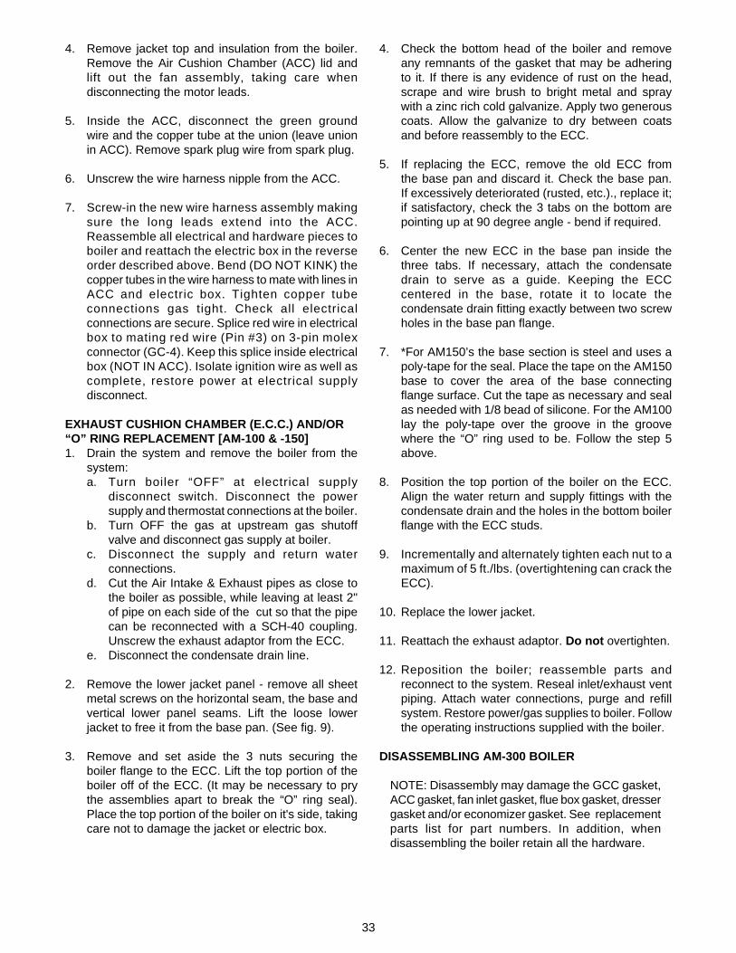
4. Remove jacket top and insulation from the boiler.Remove the Air Cushion Chamber (ACC) lid andlift out the fan assembly, taking care whendisconnecting the motor leads.
5. Inside the ACC, disconnect the green groundwire and the copper tube at the union (leave unionin ACC). Remove spark plug wire from spark plug.
6. Unscrew the wire harness nipple from the ACC.
7. Screw-in the new wire harness assembly makingsure the long leads extend into the ACC.Reassemble all electrical and hardware pieces toboiler and reattach the electric box in the reverseorder described above. Bend (DO NOT KINK) thecopper tubes in the wire harness to mate with lines inACC and electric box. Tighten copper tubeconnections gas tight. Check all electricalconnections are secure. Splice red wire in electricalbox to mating red wire (Pin #3) on 3-pin molexconnector (GC-4). Keep this splice inside electricalbox (NOT IN ACC). Isolate ignition wire as well ascomplete, restore power at electrical supplydisconnect.
EXHAUST CUSHION CHAMBER (E.C.C.) AND/OR“O” RING REPLACEMENT [AM-100 & -150]1. Drain the system and remove the boiler from the
system:a. Turn boiler “OFF” at electrical supply
disconnect switch. Disconnect the powersupply and thermostat connections at the boiler.
b. Turn OFF the gas at upstream gas shutoffvalve and disconnect gas supply at boiler.
c. Disconnect the supply and return waterconnections.
d. Cut the Air Intake & Exhaust pipes as close tothe boiler as possible, while leaving at least 2"of pipe on each side of the cut so that the pipecan be reconnected with a SCH-40 coupling.Unscrew the exhaust adaptor from the ECC.
e. Disconnect the condensate drain line.
2. Remove the lower jacket panel - remove all sheetmetal screws on the horizontal seam, the base andvertical lower panel seams. Lift the loose lowerjacket to free it from the base pan. (See fig. 9).
3. Remove and set aside the 3 nuts securing theboiler flange to the ECC. Lift the top portion of theboiler off of the ECC. (It may be necessary to prythe assemblies apart to break the “O” ring seal).Place the top portion of the boiler on it's side, takingcare not to damage the jacket or electric box.
4. Check the bottom head of the boiler and removeany remnants of the gasket that may be adheringto it. If there is any evidence of rust on the head,scrape and wire brush to bright metal and spraywith a zinc rich cold galvanize. Apply two generouscoats. Allow the galvanize to dry between coatsand before reassembly to the ECC.
5. If replacing the ECC, remove the old ECC fromthe base pan and discard it. Check the base pan.If excessively deteriorated (rusted, etc.)., replace it;if satisfactory, check the 3 tabs on the bottom arepointing up at 90 degree angle - bend if required.
6. Center the new ECC in the base pan inside thethree tabs. If necessary, attach the condensatedrain to serve as a guide. Keeping the ECCcentered in the base, rotate it to locate thecondensate drain fitting exactly between two screwholes in the base pan flange.
7. *For AM150’s the base section is steel and uses apoly-tape for the seal. Place the tape on the AM150base to cover the area of the base connectingflange surface. Cut the tape as necessary and sealas needed with 1/8 bead of silicone. For the AM100lay the poly-tape over the groove in the groovewhere the “O” ring used to be. Follow the step 5above.
8. Position the top portion of the boiler on the ECC.Align the water return and supply fittings with thecondensate drain and the holes in the bottom boilerflange with the ECC studs.
9. Incrementally and alternately tighten each nut to amaximum of 5 ft./lbs. (overtightening can crack theECC).
10. Replace the lower jacket.
11. Reattach the exhaust adaptor. Do not overtighten.
12. Reposition the boiler; reassemble parts andreconnect to the system. Reseal inlet/exhaust ventpiping. Attach water connections, purge and refillsystem. Restore power/gas supplies to boiler. Followthe operating instructions supplied with the boiler.
DISASSEMBLING AM-300 BOILER
NOTE: Disassembly may damage the GCC gasket,ACC gasket, fan inlet gasket, flue box gasket, dressergasket and/or economizer gasket. See replacementparts list for part numbers. In addition, whendisassembling the boiler retain all the hardware.

34
1. Turn gas “OFF” at supply (upstream) valve. Turnelectrical power to boiler “OFF” at disconnect switch.Disconnect gas piping and power to boiler. Isolateboiler from hydronic system and drain boiler.Disconnect supply and return water piping.
2. Disconnect the exhaust vent, as follows:a. Either cut the vent pipe in a straight section near
the boiler (leaving a sufficient straight section oneither side of this cut to rejoin later with acoupling).
b. Or remove the eight (8) nuts and washersholding the flue box (and exhaust line) to theboiler and pull flue box away from boiler. (Seefig. 12).
3. Remove the air inlet - either cut the vent pipe in astraight section near the boiler (leaving a sufficientstraight section on either side of this cut to rejoin witha coupling) or remove the air inlet as follows:a. Remove top jacket access panel, insulation,
and the lid to the air cushion chamber (ACC) byremoving six 1/4" nuts.
b. Remove the two electrical power wiresconnected to blower motor. Remove three 1/4"nuts from blower assembly mounting studs andslide blower assembly out. Then, removespacers from mounting studs.
c. From the inside of the ACC, carefully pry out theinsulation from the right side wall, first. Thenpry out the insulation from the rear wall of theACC and set aside for reuse.
d. Remove locknut from PVC air inlet adapter bylightly tapping it (counterclockwise) withhammer and screwdriver. Then, push theadapter through the rear wall of the ACC (a lighttap with a hammer may be necessary to breaksilicone seal between adapter shoulder andACC rear outside wall). See fig. 7.
4. Remove the boiler from the installation and locate itfor further disassembly.
5. Remove the jacket form the boiler as follows (retainall screws for reuse): Refer to fig. 12.a. Remove top and front access panels.b. Remove screws from upper front corner panel.
Remove panel sufficiently to disconnect quickconnections to rocker switch and lights.Remove panel.
c. Remove the lower front panel and rear upperand lower panels.
d. Remove the two screws from each side paneland lift the panels off the support rails.
6. Remove the Air Cushion Chamber (ACC) as follows(all these items will be reused):a. Remove the lid from the ACC.b. Disconnect and remove the gas supply tube
from the gas pipe to the Gas Cushion Chamber(GCC).
c. Disconnect the pressure sensing tube from theGCC assembly.
d. Remove the GCC by removing the four nutssecuring it to the Combustion Chamber Inlet.
e. Disconnect the spark plug lead from the plug.f. Remove the Combustion Chamber Inlet (flame
trap) by removing the four 3/16" Allen headscrews securing it to the Combustion Chamber.
g. Check to assure the capillary tube from thehi-limit is clear of the ACC. Where the hi-limitis mounted to the ACC, remove the bulb fromthe well and secure the capillary tube with bulbto the ACC.
h. Remove the four bolts securing the ACC to theheat exchanger.
i. Lift off the ACC (with electric and gas controls).There may be some silicon used to seal thecorners of the ACC to the heat exchanger orused on the gasket.
FIGURE 7: LOCATION OF AIR INLET ADAPTER & ORIFICE (AM-300)
3/8"
AIR INLET VENT CONNECTS HERE
AIR INLET ADAPTER
ORIFICE
AIR CUSHION CHAMB.
DRAIN HOLE
AAAAAAAAAAA
AAAAAAAAAAAAAA
AAAAAAAAAAA
FANASS'Y.STEP
BEVEL
FRONT VIEW
DRAIN HOLEAT BOTTOM

35
7. Remove the heat exchanger as follows:a. Carefully remove the insulation from the top
(front and rear) and sides of the heatexchanger. These will be reused on the newassembly.
b. Loosen the Dresser nut on the bottom of theheat exchanger connecting the 1-1/2" pipenipple to the 90° Dresser elbow.
c. Remove the 12 bolts connecting the heatexchanger to the economizer (two in front, twoin back and four on each side.)
d. Lift heat exchanger off the economizer and setit aside (it may be necessary to pry the twoassemblies apart to break the gasket seal.)
LEAK CHECK [AM-300]1. Pressure test the heat exchanger with water. Keep
pressurized for at least an hour or until leak isspotted. The leak may be small and take a whilebefore it becomes noticeable. If necessary to replaceheat exchanger, refer to replacement parts list andfollow packaged instructions.
2. Pressure test the economizer. If necessary toreplace economizer, refer to replacement part listand follow packaged instructions.
REASSEMBLING AM-300 BOILER1. Attach heat exchanger to economizer as follows:
a. If re-using the economizer, remove the oldgasket used to seal the two assemblies from theeconomizer. The top of the economizer mayhave some accumulated rust and debris. Scrapeor brush the surfaces and remove all loose dirt.If rusted, spray with zinc cold galvanizedcompound.
NOTICE: Extreme care should be taken inpositioning gasket (step 1b) and in placing theheat exchanger (step 1f) to assure the gasketremains in position. A displaced gasket willresult in a flue gas leak and noisy operation.
b. Position new gasket on the economizer asfollows:(1) Starting on the front (thickest plate orthickest section of front plate) lay the gasket onthe edge against the retaining plate. Lay thegasket on all four top surfaces of the economizerforming the corners so that the gasket is alwayson the plate. When the gasket over-laps itselfmiter cut at 45° to form an overlapping butt joint(see fig. 8).
(2) Use high temperature silicone RTV to holdthe butt together and at occasional spotsbetween the top edge of the economizer and thegasket to hold the gasket on the plate edge.
(3) Lay an approximately 4" piece of the 1/4"square braided gasket next to and overlappingthe butt joint. Use high temperature siliconeRTV to hold in place.
c. Place Dresser elbow on the pipe stub of theeconomizer. Snug the nut and leave elbowpointing up.
d. Connect the 1-1/2 TOE pipe nipple into bottomof the heat exchanger.
e. Place the “Dresser” nut and gasket componentson the pipe nipple. Secure these parts againstthe bottom head of the heat exchanger toprevent them from dropping off during handling.
f. Pick up the heat exchanger and place it on theeconomizer. The pipe (step 1d) must fit intoDresser elbow on the economizer and the boltholes in the bottom head of the heat exchangermust line up with the corresponding holes on theeconomizer bracket.
CAUTION: The heat exchanger must beaccurately placed in position to assure thegasket is not displaced. Do not slide the heatexchanger on the gasket to align the holes. Ifshifting is required pick up the heat exchanger,check that the gasket is in position and repeatstep (1f). Use of a “guide pin” in a hole on eachside of the heat exchanger can help placementwith the holes on the economizer bracket. Visu-ally check that the gasket is in place beforeproceeding.
g. Assemble the 1-1/2" nut to the Dresser elbow.h. Locate the 12 bolts, nuts and washers, and snug
up all nuts. Torque the nuts to 10 ft.-lbs. Thenretorque all the nuts in 5 ft.-lb. increments to25 ft-lbs. in a staggered pattern. Tighten nutson Dresser coupling.
i. Clean the top surface of the CombustionChamber and the “O” ring groove. Position the“O” ring in the groove. Place the CombustionChamber Inlet on the Combustion Chamberand secure with the (4) four Allen-head screws.
j. Wrap and secure the insulation from the oldboiler around the heat exchanger.
k. Replace the spark plug - use an anti-seizecompound on the threads.
2. Install the Air Cushion Chamber (ACC)a. Observe location of, and remove old gasket
from bottom flange of the ACC and install a newgasket.
b. Locate the ACC on the heat exchanger byaligning the holes in the ACC flange with theholes in the heat exchanger. Install the 90°angle clip, bolts, washers and nuts and tighten.
c. Seal openings at the outside bottom corners ofthe ACC with silicone caulk for an air tight seal.

36
3. Assemble Gas Cushion Chamber (GCC) to theCombustion Chamber Inlet. Replace the GCCgasket. Locate clamp ring and secure with 1/4"washers and nuts.
4. Attach the gas supply tube from the GCC to the gaspipe in the ACC.
5. Reconnect the pressure sensing tube on the GCC.
6. Reattach the ignition lead to the spark plug.
7. Replace lid on the ACC. NOTE: If the air inlet pipingwas disconnected at the ACC skip this step.
8. Replace and secure the hi-limit bulb making sure itis bottomed in the well. Carefully route thecapillary tube to avoid contact with sharp edges.Place excess capillary tubing flat on the top rear headof the boiler.
9. Replace the insulation on the top head of the boiler(front and rear). Replace the jacket.a. Mount the side panel bracket on the support
rails at the bottom of the economizer. Alignthe opening in the left side panel with the gasvalve.
b. Attach rear bottom, rear top and front bottompanels.
c. Before attaching the front upper panel connectthe two black leads with quick connects to theRocker Switch. Screw the front panel in place.Re-connect the red light leads (one brown andone white) and the green light leads (oneorange, one white).
REPOSITION BOILER IN ITS LOCATION [AM-300]1. If the venting was cut when the boiler was removed,
reconnect the cut sections with couplings. Cementventing joints.
2. If the venting was disconnected from the boiler:a. Use the new flue box gasket and follow
directions supplied to reattach the flue box.b. To reconnect the air inlet adapter, clean the old
silicone from the ACC's inlet adapter. Apply athin bead (approximately 3/16" wide) of siliconecaulk completely around shoulder of theadapter. Insert the adapter through the openingin the ACC. Screw the locknut onto adapter, andtighten securely.
(1) Reinstall rear wall and right side wallinsulation in the ACC (press to fit in place).
(2) Remove the gasket from the blower inletand attach a new gasket without stretching it.Align the gasket with the edge of the blowerinlet. Trim the excess and butt the ends to forma complete circle. Connection must beleak-tight.
(3) Replace spacers on the blower assemblymounting studs.
(4) Check compression marks on old gasket. Ifthe compression marks on the old gasket werenot complete and concentric around the inlet,bend the studs as required to obtain properalignment between the inlet and adapter. Ifthere is a gap between the face of the gasketand adapter, remove spacers from the studsand shorten the spacers 1/16" more than theaforementioned gap.
(5) Remount blower assembly on mountingstuds. Reinstall blower assembly nuts andtighten securely. Reconnect power leads.
(6) Replace lid on ACC and tighten nutssecurely.
FIGURE 8: ECONOMIZER (TOP VIEW)
AAAAAAAAAAAAAAAAAAAAAAAAAAAAAAAAAAAAAAAAAAAAAAAAAAAAAAAAAAAAAAAAAAAAAAAAAAAAAAAAAAAAAAAAAAAAAAAA
AA
GASKET w/ 45° MITER
BACK UP STRIP
1/4" GASKET 4" LONG
1/4" BRAID GASKET
AA

37
3. Reinstall boiler water, gas and electric connections.
4. Thoroughly purge the air from the boiler and system.Only after system is purged of air and filled with watershould the boiler be started. Follow therecommended system start-up procedure in theinstallation manual.
HEAT EXCHANGER REPLACEMENT [AM-100 & 150]1. Turn gas supply OFF at upstream supply valve. Turn
electrical supply OFF at wall disconnect switch.Disconnect gas pipe, 115V power and thermostatlines at boiler.
2. Isolate boiler from hydronic system and drain boiler.Disconnect supply and return water piping andcondensate drain line.
3. Cut air intake and exhaust lines leaving at least 2"on each side of the cut to receive a coupling forreassembly.
4. Remove the boiler from the installation and locateit for further disassembly.
5. Remove the electric box from the boiler:a. Disconnect the yellow and orange leads from
the gas valve and blue and brown leads from thehigh limit.
b. Remove the 1/8" O.D. copper regulator ventpressure line at the gas valve.
c. Inside the electric box, exiting the wire harnessdisconnect:1. Green ground wire from ground screw2. White lead from terminal #4 on terminal strip3. Ignition wire lead from the GC-4 ignition spud4. Red lead - cut wire inside electrical box and
splice later.5. Copper pressure lines exiting the wire
harness. Separate from plastic tubing andcompression fitting respectively. Bend tubesstraight and away from electric box.
d. Unscrew bushing from end of wire harness.e. Remove the four screws securing box to boiler
jacket and lift the box away from the boiler - setaside. (See fig. 10 and 11).
6. Disconnect the gas valve and gas lines, unscrew theair inlet and exhaust adapters, detach the high limitand unscrew the well from the boiler.
7. Remove all jacket screws and lift off the top lid andjacket parts from the boiler. (Refer to fig. 9).
8. Remove the Air Cushion Chamber (ACC)a. Remove the 4-1/4" nuts securing the top lid. Lift
off the lid and the spring and set them aside.b. Lift the fan assembly, disconnect the motor
leads. Remove assembly and set aside.c. Disconnect the gas line flare nut from the Gas
Cushion Chamber (GCC) and the compressionnut from the 3/16" copper pressure sensing line.
d. Disconnect the green ground lead from theCombustion Chamber and the ignition lead fromthe spark plug.
e. From the underside of the ACC, unscrew the4-1/4" nuts. LIFT OFF THE ACC.
9. Remove the (4) four nuts securing the Gas CushionChamber (GCC) from the Combustion Chamber. Liftoff the GCC and remove the flame trap from theCombustion Chamber - set them aside.
10. Remove the three nuts securing the bottom boilerflange to the Exhaust Cushion Chamber (ECC). Liftthe Heat Exchanger off the ECC. (It may benecessary to pry the assemblies apart to break theseal).
BOILER REASSEMBLY [AM-100/-150]: Check thatECC is centered in the base pan and the 3 tabs in thebase are pointed up to keep the ECC in position.1. Remove seal from the ECC and clean the top
surface of the chamber. Check the inside of thechamber and remove any loose particles.
2. Place a new seal on the ECC. To assure a leaktight seal, run a 1/4" wide bead of silicone on top ofthe seal.
3. Position the “new” Heat Exchanger by aligning thewater supply and return connections with thecondensate drain fitting and the 3 holes in the bottomflange with the studs in the ECC. Drop into place.Install the washers and nuts. Alternately andincrementally tighten the nuts to a maximum of5 ft.-lb. (Overtightening can crack the ECC).
4. Run a 1/8" dia. bead of silicone on the top edge of theheat exchanger shell. Place the silicone “U” gasketover the shell. Apply silicone to each end of thegasket and butt the ends together. If the “U” gasketis too long, cut one end to maintain a butt fit. Positionthe gasket so that the bottom is a flat plane on top ofthe Heat Exchanger.
5. Place the flame trap in the Combustion Chamber,screw the (4) four studs into Combustion Chamberflange, position the GCC gasket over the studs.

38
6. Apply an anti-sieze compound to the threads of thespark plug and screw it into the CombustionChamber.
7. Recheck the position of the “U” gasket on the HeatExchanger. Position the Air Cushion Chamber on theHeat Exchanger with the wire harness opposite thesupply and return water fitting. Align the studs on thebottom of the ACC with the brackets on the HeatExchanger and carefully place in position. Checkand straighten gasket, if necessary. Place a washerand nut on each stud. Securely attach the ACC to theHeat Exchanger by incrementally and alternatelytightening each nut.
8. Install the GCC and clamp rings, placing the greenground lead under one nut securing the GCC. Alignand tighten the gas supply tube to the GCC andconnect the 3/16" pressure sensing tube. Connectthe ignition lead to the spark plug.
9. Reattach the upper jacket panel.
10. Locate the lower jacket panel in the base pan,aligning:a. The lower jacket with the base pan holes -
screw together.b. The boiler in line with the lower jacket holes and
seams.Align all jacket holes and secure with screws.
11. Attach the high limit well, gas lines, gas valve and theair intake and exhaust adapter. Warning - Do notover-tighten plastic threaded adaptors. Install thehigh limit.
12. Mount the electric box and secure it to the jacket withthe four screws.a. Place bushing over end of wire harness.b. Inside the electric box: exiting the wire harness
connect.1. Copper pressure lines - bend the copper to
mate with the union and plastic tubing.2. Red wire - connect to red wire on Molex from
GC-4A by splicing together.3. Ignition wire - reattach to GC-4A spud.4. White wire - reattach to terminal 4 on terminal
strip.5. Ground wire - attach to screw with green wire
from GC-4.A
13. Reattach yellow and orange wires to gas valve andregulator vent pressure sensing line to regulator.
14. Reattach the brown and blue wire to the high limit.
15. Replace fan assembly (reconnect wires) spring andACC lid. Position round insulation disc on ACC lidand replace jacket lid.
16. Reposition boiler and connect to system:a. Water return and supply and condensate line.b. Air inlet and exhaust.c. Gas supply line.d. Electrical power (115V) and thermostat
connections.
17. Fill the boiler with water. Follow the Purging andStart-Up procedure in the Installation manual.Restore power and gas supplies - follow lighting/operating instructions on boiler.
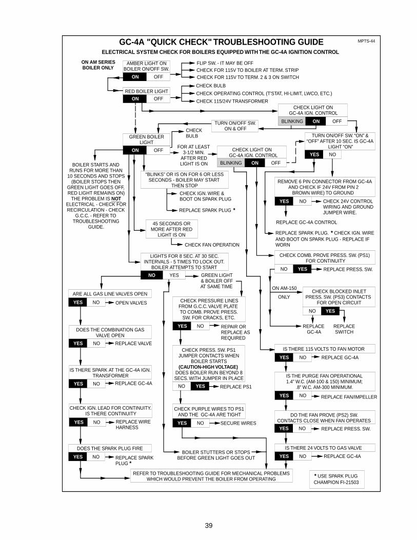
39
REPLACE FAN/IMPELLER
GC-4A "QUICK CHECK" TROUBLESHOOTING GUIDE
CHECK FAN OPERATION
FOR AT LEAST3-1/2 MIN.
AFTER REDLIGHT IS ON
CHECKBULB
FLIP SW. - IT MAY BE OFFCHECK FOR 115V TO BOILER AT TERM. STRIPCHECK FOR 115V TO TERM. 2 & 3 ON SWITCH
CHECK BULB
CHECK OPERATING CONTROL (T'STAT, HI-LIMIT, LWCO, ETC.)
CHECK 115/24V TRANSFORMER
REPLACE PRESS. SW.
CHECK 24V CONTROL WIRING AND GROUND JUMPER WIRE.
REPLACE GC-4A CONTROL
ON AM-150
ONLY
REPLACESWITCH
REPLACEGC-4A
“BLINKS” OR IS ON FOR 6 OR LESS SECONDS - BOILER MAY START
THEN STOP
45 SECONDS OR MORE AFTER RED
LIGHT IS ON
REPLACE SPARK PLUG *
GREEN LIGHT& BOILER OFFAT SAME TIME
REPLACE PRESS. SW.
REPLACE GC-4A
OPEN VALVES
REPLACE VALVE
REPLACE GC-4A
REPLACE WIRE HARNESS
REPLACE SPARK PLUG *
REPLACE PS1
SECURE WIRES
REPAIR ORREPLACE ASREQUIRED
ON
YES NO
YES NO
YES NO
YES NO
YESNO
YES NO
YESNO
YESNO
YES NO
YES NO
YES NO
YES NO
YES NO
ON OFF
ON OFF
ELECTRICAL SYSTEM CHECK FOR BOILERS EQUIPPED WITH THE GC-4A IGNITION CONTROL
ON AM SERIES BOILER ONLY
TURN ON/OFF SW.ON & OFF
REPLACE SPARK PLUG. * CHECK IGN. WIRE AND BOOT ON SPARK PLUG - REPLACE IF WORN
REFER TO TROUBLESHOOTING GUIDE FOR MECHANICAL PROBLEMS WHICH WOULD PREVENT THE BOILER FROM OPERATING
REPLACE GC-4AYES NO
CHECK IGN. WIRE &BOOT ON SPARK PLUG
BOILER STUTTERS OR STOPS BEFORE GREEN LIGHT GOES OUT
YES NO
ON OFFBLINKING
ON OFFBLINKING
MPTS-44
YES NO
ON OFF
NO YES
* USE SPARK PLUGCHAMPION FI-21503
DO THE FAN PROVE (PS2) SW.CONTACTS CLOSE WHEN FAN OPERATES
AMBER LIGHT ONBOILER ON/OFF SW.
RED BOILER LIGHT
CHECK LIGHT ONGC-4A IGN. CONTROL
GREEN BOILER LIGHT
CHECK LIGHT ONGC-4A IGN. CONTROL
TURN ON/OFF SW. “ON” & “OFF” AFTER 10 SEC. IS GC-4A
LIGHT “ON”
REMOVE 6 PIN CONNECTOR FROM GC-4A AND CHECK IF 24V FROM PIN 2
BROWN WIRE) TO GROUND
CHECK COMB. PROVE PRESS. SW. (PS1) FOR CONTINUITY
CHECK BLOCKED INLET PRESS. SW. (PS3) CONTACTS
FOR OPEN CIRCUITCHECK PRESSURE LINES FROM G.C.C. VALVE PLATE TO COMB. PROVE PRESS.
SW. FOR CRACKS, ETC.
IS THERE 115 VOLTS TO FAN MOTOR
IS THE PURGE FAN OPERATIONAL1.4" W.C. (AM-100 & 150) MINIMUM;
.8" W.C. AM-300 MINIMUM.
IS THERE 24 VOLTS TO GAS VALVE
CHECK PURPLE WIRES TO PS1 AND THE GC-4A ARE TIGHT
CHECK PRESS. SW. PS1 JUMPER CONTACTS WHEN
BOILER STARTS(CAUTION-HIGH VOLTAGE)
DOES BOILER RUN BEYOND 8 SECS. WITH JUMPER IN PLACE
DOES THE SPARK PLUG FIRE
CHECK IGN. LEAD FOR CONTINUITY. IS THERE CONTINUITY
IS THERE SPARK AT THE GC-4A IGN. TRANSFORMER
DOES THE COMBINATION GAS VALVE OPEN
ARE ALL GAS LINE VALVES OPEN
LIGHTS FOR 8 SEC. AT 30 SEC. INTERVALS - 5 TIMES TO LOCK OUT.
BOILER ATTEMPTS TO START
BOILER STARTS ANDRUNS FOR MORE THAN
10 SECONDS AND STOPS(BOILER STOPS THEN
GREEN LIGHT GOES OFF,RED LIGHT REMAINS ON)
THE PROBLEM IS NOTELECTRICAL - CHECK FORRECIRCULATION - CHECK
G.C.C. - REFER TOTROUBLESHOOTING
GUIDE.

40
REFNO. NAME OF PART PART NO. AM-100 AM-150 AM-300
1 Fiberglass Insulation Disc 70-1760 1Fiberglass Insulation Disc 70-1774 1Fiberglass Insulation Rectangle 45-1348 1
2 Air Chamber Cover Ass’y BM-7026 1Air Chamber Cover Ass’y BM-7027 1Air Chamber Cover Ass’y BM-7156 1
3 Spring 60-3513 1 14 Repl Blower Ass’y - NG BM-7132 1
Repl Blower Ass’y - NG BM-7153 1Repl Blower Ass’y - NG BM-7131 1Repl Blower Ass’y - LP BM-7100 1Repl Blower Ass’y - LP BM-7248 1Repl Blower Motor & Impeller Kit BM-7179 1 1Repl Blower Impeller Kit BM-7249 1 1
5 Repl Blower Motor BM-7199 16 Air Cushion Chamber Ass’y BM-7114 1
Air Cushion Chamber Ass’y BM-7212 1Air Cushion Chamber Ass’y BM-7152 1
7 1-1/2" NPT(Male) to 1-1/2" Socket PVC Adapter 56-5033 12" NPT (Male) to 2" Socket PVC Adapter 56-3040 13" (Male) PVC Inlet Adapter w/Locknut BM-7155 1
8 Gasket-Air Cushion Chamber BM-7192 112 Gas Supply Tube - NG BM-7112 1
Gas Supply Tube - NG BM-7154 1Gas Supply Tube - LP BM-7113 1Gas Supply Tube - NG/LP BM-7018 1
13 Gas Inlet Pipe 70-1614 1Gas Inlet Pipe 53-1208 1
14 Nipple & Orifice Ass’y - NG (Color Code - Org.) BM-7115 1Nipple & Orifice Ass’y - NG (Color Code - Wht.) BM-7215 1Nipple & Orifice Ass’y - NG (Color Code - None) BM-7159 1Nipple & Orifice Ass’y - LP (Color Code - Slv.) BM-7580 1Nipple & Orifice Ass’y - LP (Color Code - Red) BM-7230 1
15 Gas Valve 24v - NG BM-7059 1 1Gas Valve 24v - NG BM-7061 1Gas Valve 24v - LP BM-7060 1 1
SECTION 4: REPLACEMENT PARTS LIST
ORDERING INFORMATIONWhen ordering replacement parts, provide the model and serial number shown on the unitrating plate as well as the part number and name as shown in parts list Parts may be obtainedfrom your local Hydrotherm heating contractor

41
— Gas Cushion Chamber Kit - NG (Has Items 17, 18, 20) BM-7236 1Gas Cushion Chamber Kit - NG (Has Items 17, 18, 20) BM-7238 1Gas Cushion Chamber Kit - NG (Has Items 17, 18, 20) BM-7240 1Gas Cushion Chamber Kit - LP (Has Items 17, 18, 20) BM-7237 1Gas Cushion Chamber Kit - LP (Has Items 17, 18, 20) BM-7239 1
17 Gas Cushion Chamber & Diaphragm Ass’y - NG (1) BM-6003 1Gas Cushion Chamber & Diaphragm Ass’y - NG (1) BM-7013 1Gas Cushion Chamber & Diaphragm Ass’y - NG (1) BM-7151 1Gas Cushion Chamber & Diaphragm Ass’y - LP (1) BM-6008 1Gas Cushion Chamber & Diaphragm Ass’y - LP (1) BM-7014 1
18 Split Clamp Ring Set BM-7020 1Split Clamp Ring Set BM-7021 1Split Clamp Ring Set BM-7194 1
19 Valve Diaphragm Pkg (11 pcs) BM-7097 1 1Valve Diaphragm Pkg (21 pcs) BM-7197 1
20 Gasket - Gas Cushion Chamber 59-1025 1Gasket - Gas Cushion Chamber 59-1031 1Gasket - Gas Cushion Chamber 59-2012 1
21 Spark Plug (Champion FI-21503) BM-7217 1 1 122 Flame Trap Ass’y - NG BM-7087 1
Flame Trap Ass’y - NG/LP BM-7010 1Flame Trap Ass’y - LP BM-7088 1
23 Ignition Wire Ass’y BM-7157 124 Repl Pressure Sensing Tube BM-7158 128 Seal - UChannel BM-7127 1
Seal - U Channel BM-7214 129 Heat Exchanger - 30psi BM-7111 1
Heat Exchanger - 100psi BM-7208 1Heat Exchanger - 100psi BM-7149 1
30 Seal - “O”Ring 59-2008 1Seal - Gasket 3.8 ft. 59-1046 1Seal - “O”Ring 59-2010 1
31 Exhaust Chamber Ass’y BM-7110 1Exhaust Chamber Ass’y BM-7270 1
32 1-1/2" NPT(Male) to 1-1/2" Socket CPVC Adapter 56-5034 12" NPT (Male) to 2" Socket CPVC Adapter 56-3041 13" (Male) CPVC Inlet Adapter BM-7165 1
33 3" CPVC Locknut BM-7202 134 Condensate Drain Fitting 56-5709 1 1
Condensate Drain Fitting 56-5713 135 Wire Harness 40-5033 1
Wire Harness 40-5034 136 Gasket - Heat Exchanger to Economizer BM-7193 137 Combustion Chamber Inlet (Includes Item 30) BM-7150 138 Economizer - 100psi BM-7147 139 900 Elbow Coupling - 1-1/2" (w/Gaskets) 56-5908 140 Gasket Kit (For Item 39) BM-7198 241 Flue Box Ass’y (w/Items 32, 33 & 42) - Old 8 Hole Style BM-7164 1
Flue Box Ass’y (w/o Item 32) BM-7200 1Flue Box Ass'y (w/Items 32, 33 & 42) - New 8 Hole Style BM-7266
REFNO. NAME OF PART PART NO. AM-100 AM-150 AM-300
(1) Item 20 must also be ordered with Item 17.

42
42 Flue Box Gasket Only - Old 3 Hole Style BM-7201 1Flue Box Gasket Only - New 3 Hole Style 59-1046
46 Repl Control Box - NG/LP BM-7128 1Repl Control Box - NG/LP BM-7210 1
47 Combustion Prove Pressure Switch 02-4851 1 1 148 Bracket Ass’y - Pressure Switch 03-4367 1 149 Tube - Pressure Switch BM-7122 1
Tube - Pressure Switch BM-7055 150 Fan Prove Switch BM-7057 1 1
Fan Prove Switch BM-7058 151 Blocked Inlet Pressure Switch 02-4871 152 Terminal Strip, 5 Pole BM-7070 1 153 Terminal Strip, 2 Pole, Thermostat 58-2313 1 1 154 Gas Valve/Fan Prove Harness 40-5162 1
Gas Valve Harness 42-5160 1 Gas Valve Harness 40-5164 1
55 Fan Control Wire Harness 40-5163 1Fan Control Wire Harness 40-5161 1Fan Control Wire Harness 40-5264 1
57 Transformer - 115/24v BM-7105 1Transformer - 115/24v BM-7106 1Transformer - 115/24v BM-7161 1
58 Solid State Ignition Control - GC-4A BM-7256 1 1 159 Electric Sub Panel BM-7162 160 Junction Box w/Terminal Strip 4 x 4 BM-7163 161 Indicator Lamp - Red BM-7232 1 1 162 Indicator Lamp - Green BM-7233 1 1 1— Silicone Sealant - 11 oz. 10-6631 1 1 1— Urethane Tape (4 ft. long) BM-7137 1 163 Lighted ON/OFF Rocker Switch 58-1538 1 1 1FOLLOWING COMMON “STREET” PARTS MAY BE AVAILABLE FROM YOUR LOCAL WHOLESALER
64 Pressure Relief Valve - 30psi 22-1203 1 1 1Pressure Relief Valve - 50psi 22-1007 1 1Pressure Relief Valve - 75psi 22-1803 1 1Pressure Relief Valve - 100psi 22-1201 1 1
65 Temp/Press Indicator - 30 & 50psi 20-1015 1Temp/Press Indicator - 30 & 50psi 20-1003 1 1Temp/Press Indicator - 75 & 100psi 20-1011 1 1
66 Bushing - 1" x 1/4" 56-4007 1Bushing - 1-1/4" x 1/4" 56-4227 1Bushing - 1-1/4" x 1/2" (75 & 100psi T/P Indicator) 56-4228 1Bushing - 1-1/2" x 1/4" 56-4229 1Bushing - 1-1/2" x 1/2" (75 & 100psi T/P Indicator) 56-4204 1
67 Bushing - 1" x 3/4" 56-4003 2 1Bushing - 1-1/4" x 3/4" 56-4226 1Bushing - 1-1/2" x 3/4" 56-4205 2
68 Nipple - 1" x 3" T.O.E. 53-1202 2Nipple - 1-1/4" x 4" T.O.E. 53-1260 2Nipple - 1-1/2" x 3-1/2" T.O.E. 53-1326 1
69 Hose 54-3301 2Hose 54-3302 2
REFNO. NAME OF PART PART NO. AM-100 AM-150 AM-300

43
REFNO. NAME OF PART PART NO. AM-100 AM-150 AM-300
FOLLOWING COMMON “STREET” PARTS MAY BE AVAILABLE FROM YOUR LOCAL WHOLESALER70 Hose Clamp 57-4907 4
Hose Clamp 57-4906 471 Cross - 1" 56-5101 1
Cross - 1-1/4" 56-5103 1Cross - 1-1/2" 56-5104 1
72 Nipple - 1" x 16" LG 53-1206 1Nipple - 1-1/4" x 18-1/2" LG 53-1262 1Nipple - 1-1/2" x 18" LG 53-1327 1
73 Nipple - 1" x 3" LG 53-1207 1Nipple - 1-1/4" x 3" LG 53-1250 1
74 Elbow - 1" 56-3305 1Elbow - 1-1/4" 56-3306 1
75 Stud - 5/16-18 x 1-1/4" LG 44-1052 4 4 476 Well - 1/2" 02-3413 1 1
Well - 1/2" 02-3408 177 Single Hi-Limit w/o Well BM-7086 1 1
Single Hi-Limit w/o Well 02-3207 178 Pipe Plug - 1" Sq. Head 56-4550 179 Drain Valve 51-1204 1 1 180 Cap Screw - St. Stl., 1/4 x 20 x 1" LG 57-2907 481 900 Elbow - 1/2" FPT to 1/2" Comp, NG/LP 56-5515 1
900 Elbow - 1/2" FPT to 5/8" Comp, NG 56-5516 1900 Elbow - 1/2" FPT x 1/2" FPT 56-3303 1
82 Connector - Flare, 1/2 NPT x 5/8 56-5488 183 Union - 3/16 Comp 56-5500 1 2 1
Union - 3/4" 56-4801 184 Elbow - 3/4" 56-3304 2
Elbow - 1/2" 56-3303 1 185 Pipe Plug - 1/8" Sq. Hd. 56-4600 1 1 186 Bushing - 1/8" Comp 56-5499 1 1 187 Nipple - 3/4" x Close 53-1120 188 Tee - 1/4" 56-1000 189 Pipe Plug - 1/4" Sq. Hd. 56-4605 190 Connector - Comp, 3/4" x5/8" 56-5518 191 Connector - Barb, 1/8 NPT x 3/16 56-5711 292 Connector - 1/8 NPT x 3/16 Comp 56-5494 193 Bushing - 1/4" x 1/8" 56-4012 194 Tee - 3/16 ID Barb 56-5710 1 1 195 Vinyl Tubing Harness - 3/16" (9" long) 54-3212 1 1 196 Copper Tubing - 1/8" (20" long) 54-2060 1 197 Connector - Elbow, 1/4 NPT x 3/16 Comp 56-5489 1 198 Tee - 3/16 Comp 56-5492 199 Circulator Relay 26-3519 1 1

44
JACKET PARTS AND ACCESSORY KITS (Quantity: 1 each)
104 Jacket Top Cover BM-7039 BM-7040105 Jacket Upper Panel BM-7260 BM-7263106 Jacket Lower Panel BM-7261 BM-7264107 Jacket Bottom Cover BM-7144 BM-7048108 Jacket Access Panel BM-7262 BM-7265109 Jacket Lower Front Panel BM-7166110 Jacket Upper Front Panel BM-7167111 Jacket Access Front Panel BM-7168112 Jacket Lower Rear Panel BM-7171113 Jacket Upper Rear Panel BM-7170114 Jacket Top Access Panel BM-7169115 Jacket Side Panel - Right BM-7173116 Jacket Side Panel - Left BM-7172
— Touch-Up Spray Paint Kit 60-2852 60-2852 60-2852— Repl Piping Tree Kit - 30psi (2) BM-7224— Repl Piping Tree Kit - 100psi (2) BM-7225— Repl Piping Tree Kit (3) BM-7226— 5 Yr Tune-Up Kit - NG (4) BM-8197 BM-8198 BM-8199— 5 Yr Tune-Up Kit - LP (4) BM-8197 BM-8198— 5 Yr Tune-Up Kit - NG (Incl. Replacement Regul.) (5) BM-7243 BM-7245 BM-7247— 5 Yr Tune-Up Kit (Incl. Replacement Regul.) (5) BM-7244 BM-7246
REF PART NO.NO. NAME OF PART AM-100 AM-150 AM-300
(2) Includes Items 64 thru 74.(3) Includes Items 71 & 72 only.(4) Includes Items 19, 20 & 21.(5) Includes Items 19, 20 & 21 and Replacement Regulator for VR8450M Gas Valve.

45
AAAAAA
AAAAA
AA
31
29
78
85
74
84
21
18
20
17
12
83
22
6
3
2
68
68
70
70
69
69
72
737677
14
71
66
67
64
15
86
75
104
105
106
107
108
46
4
1
16 28
30
81/82
7
32
34
65
35
13
19
A79 67
FIGURE 9: GENERAL ASSEMBLY MODEL AM-100, AM-150

46
FIGURE 10: MODEL AM-100 CONTROL PANEL
FIGURE 11: MODEL AM-150 CONTROL PANEL
97 4994
47
98
63
53
57
99
52
48
95
50
96
54
55
58
61/62
51
5357
63
94
50
96
95
61/6249 97
47
54
55
5299
58
48
3
21
1 2 34 5

47
JACKET ASSEMBLYMODEL AM-300
FIGURE12: GENERAL ASSEMBLY AM-300
90
A
41
1286/15
14
85
88 23
5
21 4
83
87
7
89
64
AAAAAA
53
77
92 2 24 83 6
6566
71
72
76
17
18
20
37
30 80
8
29
3668
3938
32 & 33
34
40
8419
67
75
42
93
A79 67
1
60
59
5791 47
58
50
8495
94
54
55
110
116
111
SIDE PANEL BRACKETS
115
113
109
112
114
63
6162
A
AA
78

5211 CREEKBANK ROADMISSISSAUGA, ONTARIO L4W 1R3 CANADA(905) 625-2991 • FAX (905) 625-6610
260 NORTH ELM STREETWESTFIELD, MA 01085(413) 568-9571 • FAX (413) 568-9613


