Amplitude Modulated Systems
Communication is process of establishing connection between two points for information
exchange.
Channel refers to medium through which message travels e.g. wires, links, or free space.
Information is called baseband signal/modulating signal.
Example: Audio signal30 Hz to 20 KHz
Tone – single frequency
Modulation is the requirement of communication systems. It is a process by which some
characteristic of carrier signal is varied according to instantaneous value of modulating signal.
Types of Modulation:
Continuous wave (CW) modulation:-Carrier waveform is continuous.
Example :Amplitude and Angle modulations,
Pulse modulation: Carrier is pulse type:
Pulse Analog Modulation: PAM, PWM, PPM
Pulse Digital modulation: PCM, DM, DPCM
Digital Modulation Schemes: Used for data transmission; ASK, FSK, PSK
Need for Modulation?
(i) Multiplexing: Simultaneous transmission of multiple messages. If transmitted without
modulation they will interfere.
(ii) Size of antenna: audio frequency: 30Hz – 20 KHz
(a) For 30Hz,λ = 10,000 KM, Antenna size λ /4 = 2500 Km (Impractical)
(b) For 1 MHz carrier, λ = 300m, Antenna λ/4 = 75m (Big)
(c) For 100 MHz carrier, λ = 3m, Antenna (λ/4) = 7.5m (Practical).
(iii) Narrow banding: If baseband signal (50 Hz-20 KHz) is transmitted directly one
needs very wide band antenna. Frequency translation improves a lot typical 1:200 ratio
of band edge reduces to 1:1.01for frequency range of 1 MHz.
Amplitude Modulation (Conventional AM)
Amplitude of carrier is changed with respect to modulating signal.
It is linear modulation.
Carrier wave 𝑒𝑐 = 𝐸𝑐 cos 𝜔𝑐𝑡
Modulating signal 𝑒𝑚 = 𝐸𝑚 cos 𝜔𝑚𝑡
Modulated signal 𝑠(𝑡) = 𝐸𝑐 [1 +𝐸𝑚
𝐸𝑐cos 𝜔𝑚𝑡] 𝑐𝑜𝑠𝜔𝑐𝑡
Where, modulation index (𝜇) =𝐸𝑚
𝐸𝑐
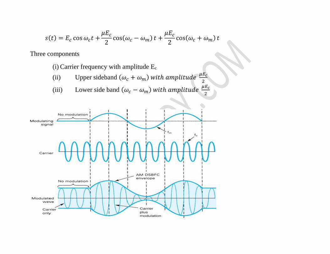
𝑠(𝑡) = 𝐸𝑐 cos 𝜔𝑐𝑡 +𝜇𝐸𝑐
2cos(𝜔𝑐 − 𝜔𝑚) 𝑡 +
𝜇𝐸𝑐
2cos(𝜔𝑐 + 𝜔𝑚) 𝑡
Three components
(i) Carrier frequency with amplitude Ec
(ii) Upper sideband (𝜔𝑐 + 𝜔𝑚) 𝑤𝑖𝑡ℎ 𝑎𝑚𝑝𝑙𝑖𝑡𝑢𝑑𝑒 𝜇𝐸𝑐
2
(iii) Lower side band (𝜔𝑐 − 𝜔𝑚) 𝑤𝑖𝑡ℎ 𝑎𝑚𝑝𝑙𝑖𝑡𝑢𝑑𝑒 𝜇𝐸𝑐
2
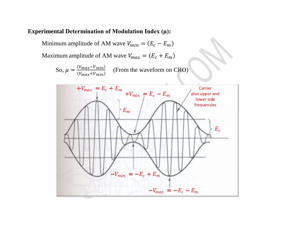
Experimental Determination of Modulation Index (μ):
Minimum amplitude of AM wave 𝑉𝑚𝑖𝑛 = (𝐸𝑐 − 𝐸𝑚)
Maximum amplitude of AM wave 𝑉𝑚𝑎𝑥 = (𝐸𝑐 + 𝐸𝑚)
So, 𝜇 =(𝑉𝑚𝑎𝑥−𝑉𝑚𝑖𝑛)
(𝑉𝑚𝑎𝑥+𝑉𝑚𝑖𝑛) (From the waveform on CRO)
Carrier plus upper and
lower side frequencies
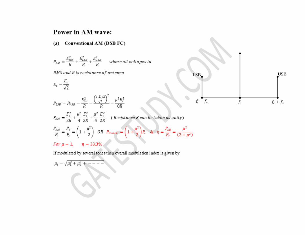
LSB USB
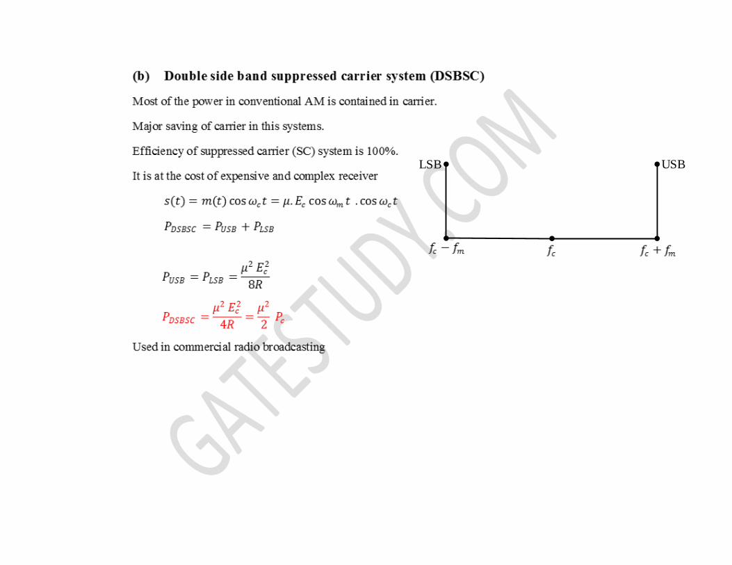
LSB USB
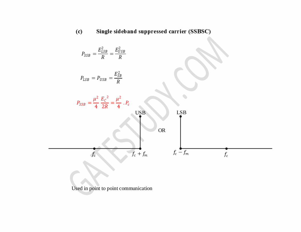
USB LSB
OR
Used in point to point communication
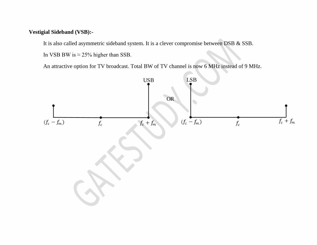
Vestigial Sideband (VSB):-
It is also called asymmetric sideband system. It is a clever compromise between DSB & SSB.
In VSB BW is ≈ 25% higher than SSB.
An attractive option for TV broadcast. Total BW of TV channel is now 6 MHz instead of 9 MHz.
USB LSB
OR
AM Modulators
Modulation translates the message spectrum upward in frequency and demodulation is downward frequency
translation
Upward frequency translation achieved by multiplier.
Types of Modulators
Multiplier Modulator: Using analog multiplier
Nonlinear Modulators: Using nonlinear devices like diode
Switching Modulator: Multiplication operation can be achieved by simple switching operation.
Balanced Modulator or Ring Modulator: Used for generation of DSB-SC wave. It suppresses unwanted
carrier.
SSB generation: Using analog multiplier & BPF. It can be also be used for VSB
AM Demodulation or Detection: To extract baseband signal from conventional AM. DSB-SC and SSB
modulation require coherent detection (complex in nature)
Two Types of AM Detectors
Square law detector: For low level modulated signals (<1V), square law region of diode characteristic is
used. This circuit gives distortion.
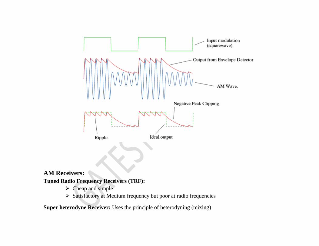
Linear diode detector or peak detector or envelope detector: Extracts envelope of AM wave. It is simple
and cheap (one diode, one capacitor) and one resistor

Operation of Envelope Detector
When AM wave amplitude increases capacitor voltage is increased. When input falls, capacitor voltage is
reduced (discharged through R).
Choice of time constant
To keep RC large compared to period of carrier wave to reduce fluctuations in detected envelope. If it is too
high discharge curves is horizontal, the negative peak may be missing. This distortion is called diagonal
clipping, so it is chosen as
1
𝑓𝑚≫ 𝜏(𝑅𝐶) ≫
1
𝑓𝑐
Above condition is possible only if 𝑓𝑐 ≫ 𝑓𝑚
AM Receivers:
Tuned Radio Frequency Receivers (TRF):
Cheap and simple
Satisfactory at Medium frequency but poor at radio frequencies
Super heterodyne Receiver: Uses the principle of heterodyning (mixing)
Advantages:
No variation in bandwidth
High sensitivity and selectivity
High adjacent channel rejection
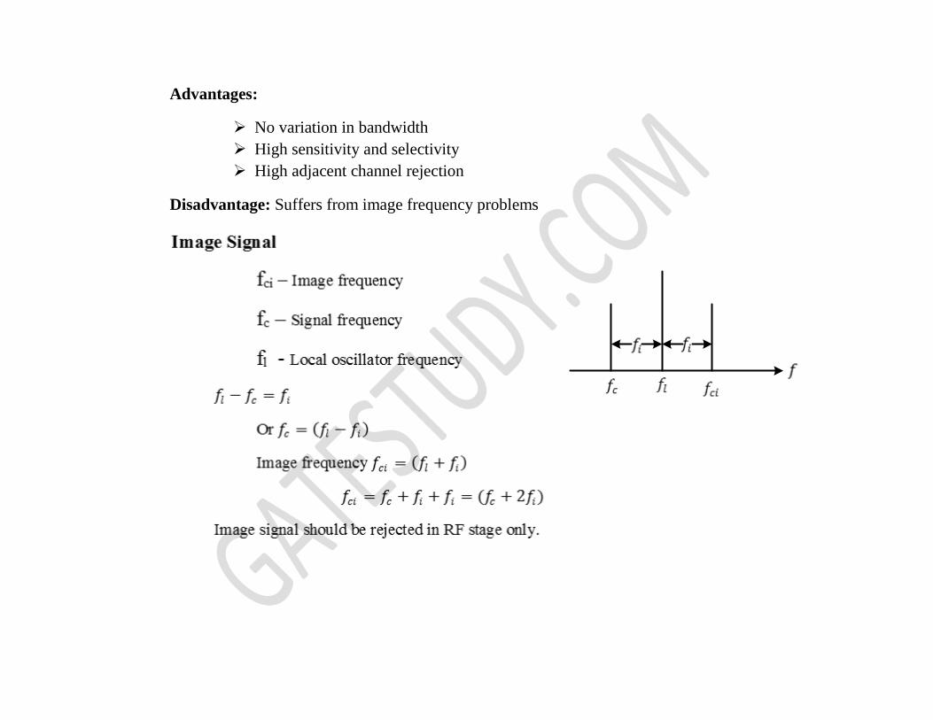
Disadvantage: Suffers from image frequency problems
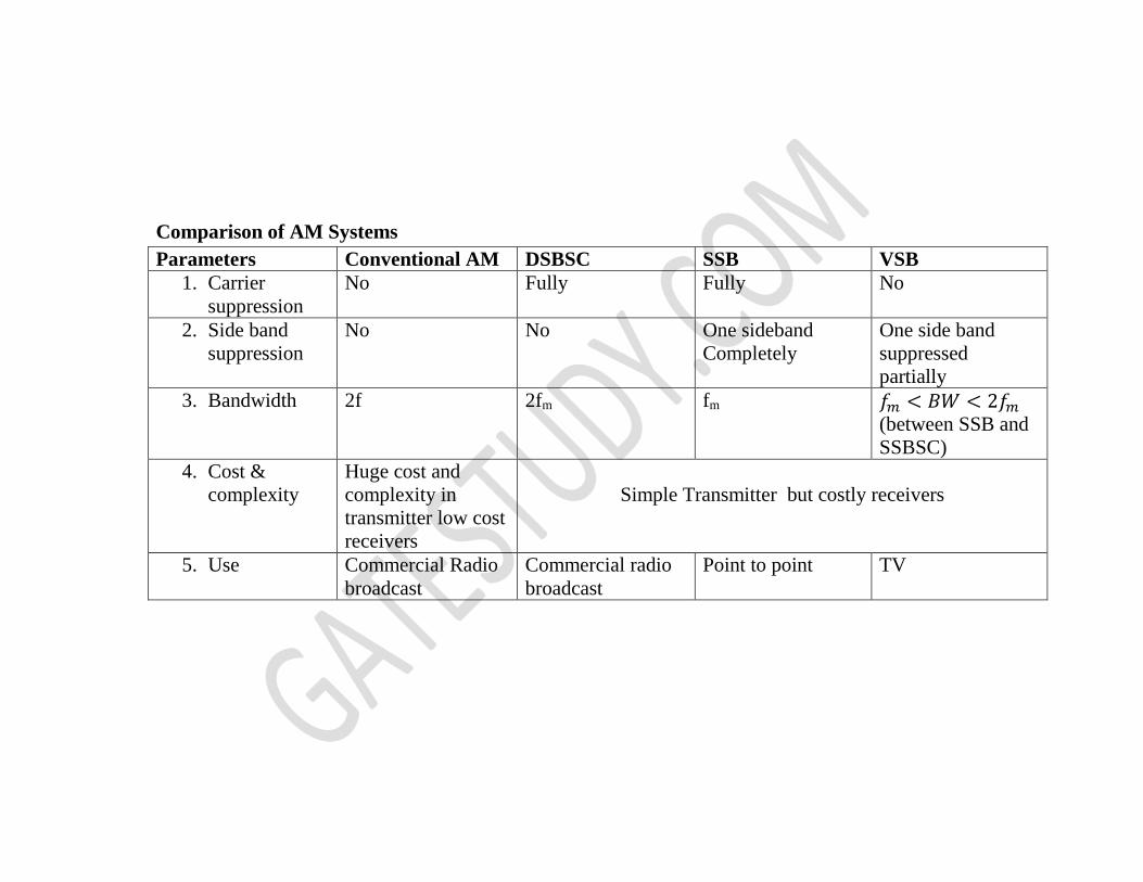
Comparison of AM Systems
Parameters Conventional AM DSBSC SSB VSB
1. Carrier
suppression
No Fully Fully No
2. Side band
suppression
No No One sideband
Completely
One side band
suppressed
partially
3. Bandwidth 2f 2fm fm 𝑓𝑚 < 𝐵𝑊 < 2𝑓𝑚
(between SSB and
SSBSC)
4. Cost &
complexity
Huge cost and
complexity in
transmitter low cost
receivers
Simple Transmitter but costly receivers
5. Use Commercial Radio
broadcast
Commercial radio
broadcast
Point to point TV