
Engineering Fracture Mechanics 71 (2004) 1791–1803
www.elsevier.com/locate/engfracmech
Analysis of non-localized creep induced strainsand stresses in notches
J.E. Nu~nez, G. Glinka *
Department of Mechanical Engineering, University of Waterloo, Waterloo, Ont., Canada N2L3G1
Received 23 December 2002; received in revised form 3 June 2003; accepted 11 June 2003
Abstract
A method for the estimation of time-dependent strains and stresses induced in notches has been developed. The aim
of the method is to generate a solution for the creep strain and stress at the notch root based on the linear-elastic stress
state, the constitutive law, and the material creep model. The proposed solution is an extension of Neuber�s total strainenergy density rule for the case of time-independent deformation. The method was derived for both localized and non-
localized creep in a notched body. Predictions were compared with finite element data and good agreement was ob-
tained for various geometrical and material configurations in plane stress conditions.
� 2003 Published by Elsevier Ltd.
Keywords: Notches; Non-localized creep; Plane stress; Stress–strain analysis
1. Introduction
As machines and engineering structures become more efficient, they require that their components have
more complex geometries with various discontinuities such as holes, grooves, and notches. It is well known
that these geometrical discontinuities induce a localized high stress concentration zone where stresses may
exceed the yield limit of the material. Mechanical components work often in very demanding conditions
such as a combination of high cyclic stresses with a high operating temperature. In the case of time- and
temperature-dependent deformations (creep) the durability analysis requires detailed knowledge of strainsand stresses in the stress concentration zone.
An accurate estimation of these local time-dependent stresses and strains can be generated by using a
finite element method analysis, however the visco-plastic finite element programs are expensive, and such
analyses are time consuming, particularly when simulating lengthy cyclic loading histories. Therefore, al-
ternative more efficient methods are required to perform an estimation of stresses and strains at the notch
root without compromising the accuracy.
* Corresponding author. Tel.: +1-519-888-4567; fax: +1-519-888-6197.
E-mail address: [email protected] (G. Glinka).
0013-7944/$ - see front matter � 2003 Published by Elsevier Ltd.
doi:10.1016/S0013-7944(03)00208-X
Nomenclature
A Norton�s power law coefficientCp plastic zone correction factor
E Young�s modulus
Kt theoretical stress concentration factor
Ke actual strain concentration factor
Kr actual stress concentration factor
KX total strain energy density concentration factor
rp plastic zone size
Drp plastic zone size incrementt time
Dtn nth time increment
a stress exponent for creep power law
b time exponent for creep power law
e022 total strain component from elastic–plastic solution
ect22 time-dependent creep strain component at the notch tip
ee22 elastic strain at the notch tip from linear elastic solution
eet22 time-dependent elastic strain component at the notch tip
ef22 elastic strain component in a far field point
ep022 mechanically induced plastic strain at t ¼ 0:0
r022 total stress from elastic–plastic solution
re22 elastic stress at the notch tip from linear elastic solution
rf22 elastic stress component in a far field point
rt22 time-dependent stress component
Xe total strain energy density at the notch tip from linear-elastic analysis
Xf total strain energy density in a far field point
1792 J.E. Nu~nez, G. Glinka / Engineering Fracture Mechanics 71 (2004) 1791–1803
To date, only a few authors have tried to develop alternative solutions for localized time-dependentcreep–plasticity problems. In 1978, Chaudonneret [1] suggested that Neuber�s rule [2] could be expressed in
its differential form as long as the applied stress increases monotonically and is a continuous function of
time. Chaudonneret and Culie [3] demonstrated that the differential form of Neuber�s rule could be suc-
cessfully used to predict notch root stresses and strains in creeping bodies under static and cyclic loading.
However a very complex integration procedure had to be incorporated to solve the proposed differential
equation, especially when creep strain was present in the net section of the specimen.
In 1984, Kurath [4] utilized a modified form of Neuber�s rule to simulate the notch root stress–strain
time-dependent behaviour in components made of titanium alloy, and acceptable fatigue life predictionswere obtained in comparison with experimental data. Kubo and Ohji [5] extended their ‘‘small scale creep’’
concept, originally proposed for cracks under elastic–creep conditions, to notches under plane strain and
axisymmetric bodies. The results obtained using the method by Kubo and Ohji are limited to cases where
the creep is strictly localized and does not consider the effect of creep away from the notch tip.
More recently, Moftakhar et al. [6] proposed an extension of Neuber�s rule [2] to estimate creep induced
multiaxial strains and stresses at the notch tip. Their approach was developed assuming that the total
strain energy density at the notch tip does not change when going from a linear elastic solution to a
J.E. Nu~nez, G. Glinka / Engineering Fracture Mechanics 71 (2004) 1791–1803 1793
time-dependent elastic–plastic–creep solution. Nevertheless, this assumption may be valid only for cases
where the deformation is strictly localized around the point of stress concentration. In 1998, Harkegard and
Sorbo [7] reformulated Chaudonneret�s model to predict creep stresses and strains in notches under con-
stant nominal stress and constant nominal strain. The authors reduced the integration complexity ofChaudonneret�s model [1] by making extensive use of normalized forms of stress, strain and time. Good
agreement was reported against generated finite element data.
The method presented below is also based on the Neuber concept but the formulation and the numerical
procedure exhibit relatively high degree of time efficiency and accuracy.
2. Application of Neubers rule to creep analysis
Neuber�s rule [2] was initially proposed for elastic–plastic notched bodies in pure shear stress state. The
rule is most often presented in terms relating the theoretical elastic stress concentration factor, Kt, and the
actual stress and strain concentration factors,
K2t ¼ KrKe: ð1Þ
Neuber�s rule can also be written in the form relating the hypothetical stress reij and the corresponding
elastic strain eeij components to the actual elastic–plastic stress r0ij and strain components e0ij
reije
eij ¼ r0
ije0ij: ð2Þ
In such a case, Eq. (1) for notched bodies in plane stress reduces to
re22e
e22 ¼ r0
22e022: ð3Þ
Eq. (3) results directly from the original Neuber�s rule (1) and it can be interpreted as an equivalence of the
total strain energy density.
Moftakhar et al. [6] showed that the total strain energy density at the notch tip, X ¼ re22e
e22, remains
almost constant as long as the plastic deformation remains a local event, even when stresses relax due to
creep. In other words, Neuber�s rule can be directly extended to time-dependent stress and strain analysis in
the following way,
X ¼ re22e
e22 ¼ r0
22e022 ¼ rt
22et22; ð4Þ
where the term on the right-hand side represents the total strain energy density at a specific time, t, underconstant nominal stress and constant temperature. It has been shown [8] that as long as the plastic yielding
and creep remain a local event limited to the zone near the notch tip, Neuber�s rule will always overestimate
the actual elastic–plastic strains and stresses. Therefore, some authors have called this the upper bound
solution as opposed to the ESED method proposed by Molski and Glinka [9], which is believed to give a
lower bound solution.
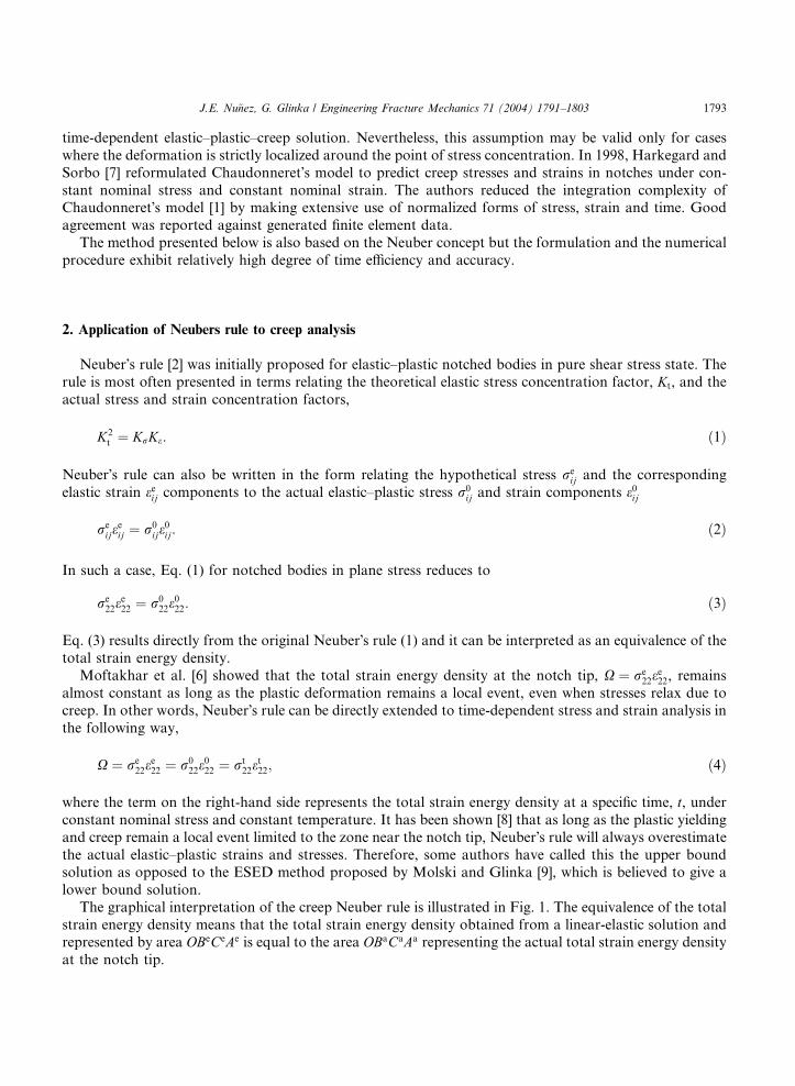
The graphical interpretation of the creep Neuber rule is illustrated in Fig. 1. The equivalence of the total
strain energy density means that the total strain energy density obtained from a linear-elastic solution andrepresented by area OBeCeAe is equal to the area OBaCaAa representing the actual total strain energy density
at the notch tip.
Fig. 1. (a) Stress distribution in notched specimen under tension loading. (b) Graphical interpretation of the Neuber�s rule approach to
creep analysis.
1794 J.E. Nu~nez, G. Glinka / Engineering Fracture Mechanics 71 (2004) 1791–1803
3. Localized creep formulation
Consider a notched body at constant temperature and subjected to constant load for an extended period
of time. As long as the creep is localized it is reasonable to assume after Neuber that
r022e
022 ¼ rt
22et22: ð5Þ
The time-dependent strain can be decomposed into its elastic eet22, mechanically induced plastic epð0Þ22 , and
creep ect22 contributions,
et22 ¼ eet22 þ ep022 þ ect22: ð6Þ
The mechanically induced plastic strain, ep022, is considered to be constant during the hold time period, since
it represents the non-recoverable plastic deformation at time t ¼ 0:0. This assumption suggests that during
the hold time there is only a trade off between the elastic unloading and creep deformation. Substituting Eq.
(6) into Eq. (5) results in
r022e
022 ¼ rt
22eet22 þ rt
22ep022 þ rt
22ect22: ð7Þ
Differentiating Eq. (7) with respect to time leads to the following equation:
0:0 ¼ rt22 _e
et22 þ _rt
22eet22 þ _rt
22ep022 þ rt
22 _ect22 þ _rt
22ect22: ð8Þ
For a uniaxial stress state at the notch tip, the elastic strain can always be obtained as eet22 ¼ rt22=E. The
elastic strain rate, on the other hand, is defined as _eet22 ¼ _rt22=E. Therefore, Eq. (8) can be written in the
following form:
0:0 ¼ 2
Ert22 _r
t22 þ _rt
22ep022 þ rt
22 _ect22 þ _rt
22ect22: ð9Þ
Eq. (9) is the general differential equation which together with the material creep law forms the set of two
equations needed for the mathematical formulation of the problem. A closed form solution to the two
equations is seldom feasible particularly when creep models take complex mathematical forms. Moftakharet al. [6] proposed a special time integration method to generate a suitable numerical solution. It was
suggested to divided the integration time period into a finite number of discrete steps, Dtn, and then to
J.E. Nu~nez, G. Glinka / Engineering Fracture Mechanics 71 (2004) 1791–1803 1795
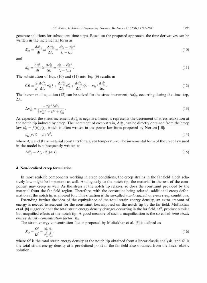
generate solutions for subsequent time steps. Based on the proposed approach, the time derivatives can be
written in the incremental form as
_rt22 ¼
drt22
dtffi Drtn
22
Dtn¼ rtn
22 � rtn�1
22
tn � tn�1
ð10Þ
and
_ect22 ¼dect22dt
ffi Decn22Dtn
¼ ecn22 � ecn�1
22
tn � tn�1
: ð11Þ
The substitution of Eqs. (10) and (11) into Eq. (9) results in
0:0 ¼ 2
EDrtn
22
Dtnrtn�1
22 þ Drtn22
Dtnep022 þ
Drtn22
Dtnecn22 þ rtn�1
22
Decn22Dtn
: ð12Þ
The incremental equation (12) can be solved for the stress increment, Drtn22, occurring during the time step,
Dtn.
Drtn22 ¼
�rtn�1
22 Decn222E r
tn�1
22 þ ep0 þ ecn22: ð13Þ
As expected, the stress increment Drtn22 is negative; hence, it represents the decrement of stress relaxation at
the notch tip induced by creep. The increment of creep strain, Decn22, can be directly obtained from the creeplaw _ec22 ¼ f ðrÞgðtÞ, which is often written in the power law form proposed by Norton [10]:
_ec22ðr; tÞ ¼ Aratb; ð14Þ
where A, a and b are material constants for a given temperature. The incremental form of the creep law usedin the model is subsequently written as
Decn22 ¼ Dtn � _ec22ðr; tÞ: ð15Þ
4. Non-localized creep formulation
In most real-life components working in creep conditions, the creep strains in the far field albeit rela-
tively low might be important as well. Analogously to the notch tip, the material in the rest of the com-
ponent may creep as well. As the stress at the notch tip relaxes, so does the constraint provided by the
material from the far field region. Therefore, with the constraint being relaxed, additional creep defor-
mation at the notch tip is allowed for. This situation is the so-called non-localized, or gross creep conditions.
Extending further the idea of the equivalence of the total strain energy density, an extra amount of
energy is needed to account for the constraint loss imposed on the notch tip by the far field. Moftakhar
et al. [8] suggested that the total strain energy density changes occurring in the far field, Xfc, produce similarbut magnified effects at the notch tip. A good measure of such a magnification is the so-called total strain
energy density concentration factor, KX.
The strain energy concentration factor proposed by Moftakhar et al. [6] is defined as
KX ¼ Xe
Xf¼ re
22ee22
rf22e
f22
; ð16Þ
where Xe is the total strain energy density at the notch tip obtained from a linear elastic analysis, and Xf is
the total strain energy density at a pre-defined point in the far field also obtained from the linear elasticsolution.
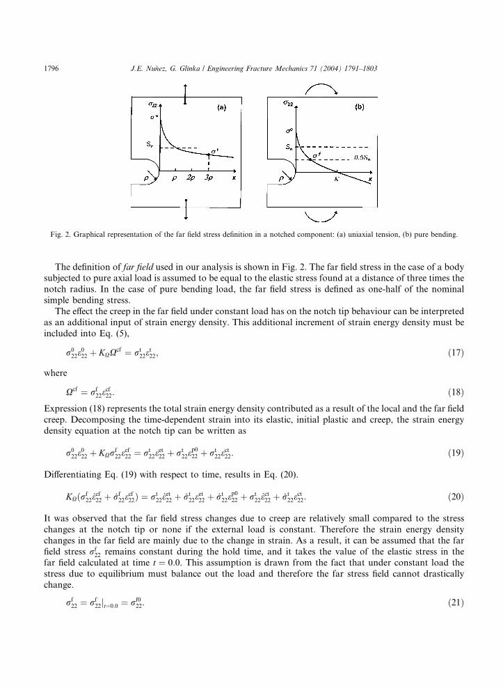
Fig. 2. Graphical representation of the far field stress definition in a notched component: (a) uniaxial tension, (b) pure bending.
1796 J.E. Nu~nez, G. Glinka / Engineering Fracture Mechanics 71 (2004) 1791–1803
The definition of far field used in our analysis is shown in Fig. 2. The far field stress in the case of a bodysubjected to pure axial load is assumed to be equal to the elastic stress found at a distance of three times the
notch radius. In the case of pure bending load, the far field stress is defined as one-half of the nominal
simple bending stress.
The effect the creep in the far field under constant load has on the notch tip behaviour can be interpreted
as an additional input of strain energy density. This additional increment of strain energy density must be
included into Eq. (5),
r022e
022 þ KXX
cf ¼ rt22e
t22; ð17Þ
where
Xcf ¼ rf22e
cf22: ð18Þ
Expression (18) represents the total strain energy density contributed as a result of the local and the far field
creep. Decomposing the time-dependent strain into its elastic, initial plastic and creep, the strain energy
density equation at the notch tip can be written as
r022e
022 þ KXr
f22e
cf22 ¼ rt
22eet22 þ rt
22ep022 þ rt
22ect22: ð19Þ
Differentiating Eq. (19) with respect to time, results in Eq. (20).
KXðrf22 _e
cf22 þ _rf
22ecf22Þ ¼ rt
22 _eet22 þ _rt
22eet22 þ _rt
22ep022 þ rt
22 _ect22 þ _rt
22ect22: ð20Þ
It was observed that the far field stress changes due to creep are relatively small compared to the stress
changes at the notch tip or none if the external load is constant. Therefore the strain energy density
changes in the far field are mainly due to the change in strain. As a result, it can be assumed that the far
field stress rf22 remains constant during the hold time, and it takes the value of the elastic stress in the
far field calculated at time t ¼ 0:0. This assumption is drawn from the fact that under constant load the
stress due to equilibrium must balance out the load and therefore the far stress field cannot drasticallychange.
rf22 ¼ rf
22jt¼0:0 ¼ rf022: ð21Þ
J.E. Nu~nez, G. Glinka / Engineering Fracture Mechanics 71 (2004) 1791–1803 1797
Furthermore, the elastic strains can be replaced according to the Hooke law by stress. After subsequent
substitutions Eq. (20) can be reduced to
KXrf022 _e
cf22 ¼
2
Ert22 _r
t22 þ _rt
22ep022 þ rt
22 _ect22 þ _rt
22ect22: ð22Þ
In order to obtain the recursive form of the general differential equation, Eqs. (10) and (11) need to be
substituted into Eq. (22).
KXrf022
Decfn22
Dtn¼ 2
EDrtn
22
Dtnrtn�1
22 þ Drtn22
Dtnep022 þ
Drtn22
Dtnecn22 þ rtn�1
22
Decn22Dtn
: ð23Þ
Solving for the actual stress increment, Drtn22, at the notch tip, the following expression is obtained:
Drtn22 ¼
KXrf022De
cfn22 � rtn�1
22 Decn222E r
tn�1
22 þ ep0 þ ecn22; ð24Þ
where
jKXrf022De
cfn22 j < jrtn�1
22 Decn22j: ð25Þ
Eq. (24) is valid as long as inequality (25) is true. Some combinations of load conditions and componentgeometry may cause the left-hand side term of expression (25) to be greater than the term on the right-hand
side. However, such situations are seldom encountered.
5. Plastic zone adjustment
Moftakhar et al. [8] has shown that in case of the presence of gross creep plasticity, Neuber�s rule ap-
proach tends to under estimate the real stresses and strains at the notch tip. In order to correct for such an
effect, a correction needs to be introduced for the calculation of the initial total strain energy density ob-
tained from the linear elastic analysis. Therefore, Glinka [11] introduced the plastic zone correction factorin order to compensate for the stress redistribution occurring in the notch tip region caused by the localized
plastic yielding. This correction factor was derived analogously to Irwin�s [12] plastic zone correction factor
proposed for sharp notches and cracks.
Glinka�s plastic zone correction factor, Cp, has been defined as,
Cp ¼ 1þ Drprp
: ð26Þ
A complete procedure of how the plastic zone size, rp, and the plastic zone increment, Drp, can be estimated
for components subjected to tension and pure bending is given in Ref. [11].
Once the plastic zone correction factor is estimated, the total strain energy density equation (19) can be
written as
r022e
022 þ KXCp
� �rf22e
cf22 ¼ rt
22eet22 þ rt
22ep022 þ rt
22ect22: ð27Þ
The resulting final expression for the calculation of the stress increment at the notch tip is
Drtn22 ¼
ðKXCpÞrf022De
cfn22 � rtn�1
22 Decn222E r
tn�1
22 þ ep0 þ ecn22: ð28Þ
And the actual strain increment can be calculated as
Detn22 ¼ Decn22 �Drtn
22
E: ð29Þ
1798 J.E. Nu~nez, G. Glinka / Engineering Fracture Mechanics 71 (2004) 1791–1803
6. Validation of the proposed model
In order to assess the accuracy of the proposed model, finite element analyses of creep in notched
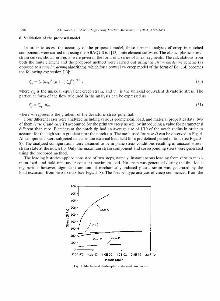
components were carried out using the ABAQUS 6.1 [13] finite element software. The elastic–plastic stress–strain curves, shown in Fig. 3, were given in the form of a series of linear segments. The calculations from
both the finite element and the proposed method were carried out using the strain hardening scheme (as
opposed to a time hardening algorithm), which for a power law creep model of the form of Eq. (14) becomes
the following expression [13]:
_eceq ¼ ðAðreqÞa½ðbþ 1Þeceq�bÞ1=bþ1
; ð30Þ
where eceq is the uniaxial equivalent creep strain, and req is the uniaxial equivalent deviatoric stress. The
particular form of the flow rule used in the analyses can be expressed as
_ecij ¼ _eceq � nij; ð31Þ
where nij represents the gradient of the deviatoric stress potential.
Four different cases were analyzed including various geometrical, load, and material properties data; two
of them (case C and case D) accounted for the primary creep as well by introducing a value for parameter bdifferent than zero. Elements at the notch tip had an average size of 1/10 of the notch radius in order to
account for the high strain gradient near the notch tip. The mesh used for case D can be observed in Fig. 4.
All components were subjected to a constant external load held for a pre-defined period of time (see Figs. 5–
8). The analyzed configurations were assumed to be in plane stress conditions resulting in uniaxial stress–
strain state at the notch tip. Only the maximum strain component and corresponding stress were generatedusing the proposed method.
The loading histories applied consisted of two steps, namely: instantaneous loading from zero to maxi-
mum load, and hold time under constant maximum load. No creep was generated during the first load-
ing period; however, significant amount of mechanically induced plastic strain was generated by the
load excursion from zero to max (see Figs. 5–8). The Neuber-type analysis of creep commenced from the
Fig. 3. Mechanical elastic–plastic stress–strain curves.
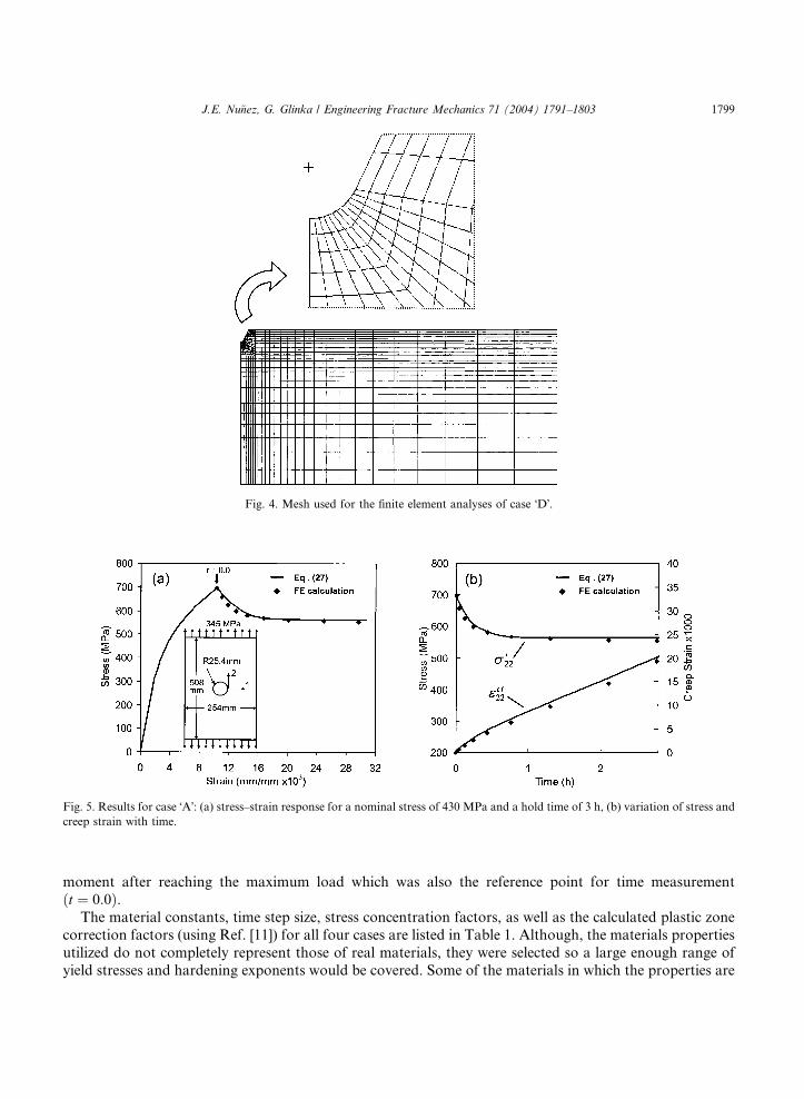
Fig. 4. Mesh used for the finite element analyses of case �D�.
Fig. 5. Results for case �A�: (a) stress–strain response for a nominal stress of 430 MPa and a hold time of 3 h, (b) variation of stress and
creep strain with time.
J.E. Nu~nez, G. Glinka / Engineering Fracture Mechanics 71 (2004) 1791–1803 1799
moment after reaching the maximum load which was also the reference point for time measurement
ðt ¼ 0:0Þ.The material constants, time step size, stress concentration factors, as well as the calculated plastic zone
correction factors (using Ref. [11]) for all four cases are listed in Table 1. Although, the materials properties
utilized do not completely represent those of real materials, they were selected so a large enough range of
yield stresses and hardening exponents would be covered. Some of the materials in which the properties are
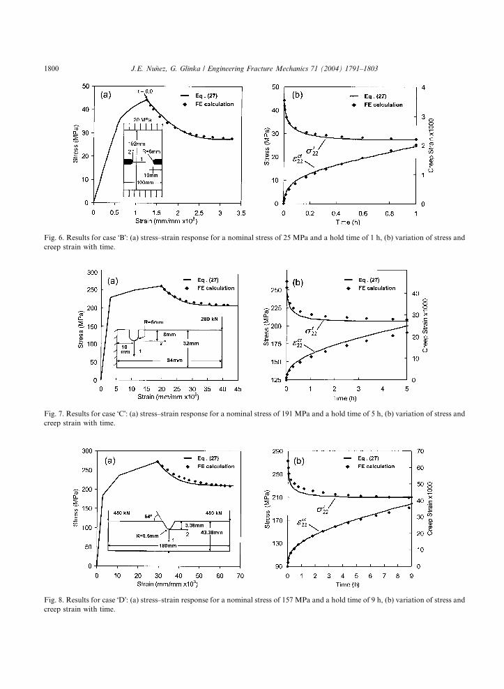
Fig. 6. Results for case �B�: (a) stress–strain response for a nominal stress of 25 MPa and a hold time of 1 h, (b) variation of stress and
creep strain with time.
Fig. 8. Results for case �D�: (a) stress–strain response for a nominal stress of 157 MPa and a hold time of 9 h, (b) variation of stress and
creep strain with time.
Fig. 7. Results for case �C�: (a) stress–strain response for a nominal stress of 191 MPa and a hold time of 5 h, (b) variation of stress and
creep strain with time.
1800 J.E. Nu~nez, G. Glinka / Engineering Fracture Mechanics 71 (2004) 1791–1803
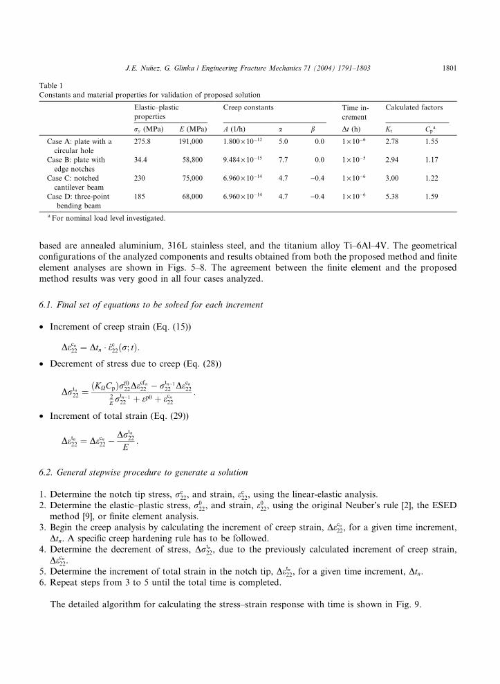
Table 1
Constants and material properties for validation of proposed solution
Elastic–plastic
properties
Creep constants Time in-
crement
Calculated factors
ry (MPa) E (MPa) A (1/h) a b Dt (h) Kt Cpa
Case A: plate with a
circular hole
275.8 191,000 1.800· 10�12 5.0 0.0 1· 10�6 2.78 1.55
Case B: plate with
edge notches
34.4 58,800 9.484· 10�15 7.7 0.0 1· 10�5 2.94 1.17
Case C: notched
cantilever beam
230 75,000 6.960· 10�14 4.7 )0.4 1· 10�6 3.00 1.22
Case D: three-point
bending beam
185 68,000 6.960· 10�14 4.7 )0.4 1· 10�6 5.38 1.59
a For nominal load level investigated.
J.E. Nu~nez, G. Glinka / Engineering Fracture Mechanics 71 (2004) 1791–1803 1801
based are annealed aluminium, 316L stainless steel, and the titanium alloy Ti–6Al–4V. The geometricalconfigurations of the analyzed components and results obtained from both the proposed method and finite
element analyses are shown in Figs. 5–8. The agreement between the finite element and the proposed
method results was very good in all four cases analyzed.
6.1. Final set of equations to be solved for each increment
• Increment of creep strain (Eq. (15))
Decn22 ¼ Dtn � _ec22ðr; tÞ:• Decrement of stress due to creep (Eq. (28))
Drtn22 ¼
ðKXCpÞrf022De
cfn22 � rtn�1
22 Decn222E r
tn�1
22 þ ep0 þ ecn22:
• Increment of total strain (Eq. (29))
Detn22 ¼ Decn22 �Drtn
22
E:
6.2. General stepwise procedure to generate a solution
1. Determine the notch tip stress, re22, and strain, ee22, using the linear-elastic analysis.
2. Determine the elastic–plastic stress, r022, and strain, e022, using the original Neuber�s rule [2], the ESED
method [9], or finite element analysis.
3. Begin the creep analysis by calculating the increment of creep strain, Decn22, for a given time increment,
Dtn. A specific creep hardening rule has to be followed.
4. Determine the decrement of stress, Drtn22, due to the previously calculated increment of creep strain,
Decn22.5. Determine the increment of total strain in the notch tip, Detn22, for a given time increment, Dtn.6. Repeat steps from 3 to 5 until the total time is completed.
The detailed algorithm for calculating the stress–strain response with time is shown in Fig. 9.
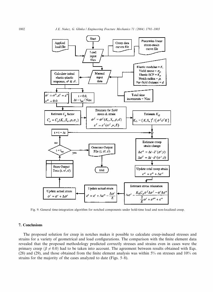
Fig. 9. General time-integration algorithm for notched components under hold-time load and non-localized creep.
1802 J.E. Nu~nez, G. Glinka / Engineering Fracture Mechanics 71 (2004) 1791–1803
7. Conclusions
The proposed solution for creep in notches makes it possible to calculate creep-induced stresses and
strains for a variety of geometrical and load configurations. The comparison with the finite element data
revealed that the proposed methodology predicted correctly stresses and strains even in cases were the
primary creep ðb 6¼ 0:0Þ had to be taken into account. The agreement between results obtained with Eqs.
(28) and (29), and those obtained from the finite element analysis was within 5% on stresses and 10% on
strains for the majority of the cases analyzed to date (Figs. 5–8).
J.E. Nu~nez, G. Glinka / Engineering Fracture Mechanics 71 (2004) 1791–1803 1803
The method can be easily programmed and it yields good results for various creep data and creep
hardening models. It is particularly suitable for simulating creep deformation in notches under constant
load. However, it is anticipated that the method can be extended for variable loading such as those in
components subjected to cyclic loading.
References
[1] Chaudonneret M. Calcul de concentrations de contrainte en elastoviscoplasticit�e, PhD Thesis Dissertation, Office Natl d�Etudes etde Recherches Aerospatiales (ONERA), Chatillon, France, 1978.
[2] Neuber H. Theory of stress concentration for shear-strained prismatic bodies with arbitrary nonlinear stress–strain law. J Appl
Mech, Trans ASME 1961;28:544–51.
[3] Chaudonneret M, Culie JP. Adaptation of Neuber�s theory to stress concentration in viscoplasticity. Rech Aerospatiale (English
Edition) 1985;(4):33–40.
[4] Kurath P. Extension of the local strain fatigue analysis concepts to incorporate time dependent deformation in Ti–6Al–4V at room
temperature, T&AM Report no. 464. Urbana, IL, USA: The University of Illinois; 1984.
[5] Kubo S, Ohji K. Development of simple methods for predicting plane-strain and axi-symmetric stress relaxation at notches in
elastic–creep bodies. In: Proceedings of the International Conference on Creep. Tokyo, Japan: JSME; 1986. p. 417–22.
[6] Moftakhar A, Glinka G, Scarth D, Kawa D. Multiaxial stress–strain creep analysis for notches. In: ASTM Special Technical
Publication 1184. Philadelphia, PA, USA: ASTM; 1994. p. 230–43.
[7] Harkegard G, Sorbo S. Applicability of Neuber�s rule to the analysis of stress and strain concentration under creep conditions.
J Engng Mater Technol, Trans ASME 1998;120(3):224–9.
[8] Moftakhar A, Buczynski A, Glinka G. Calculation of elasto-plastic strains and stresses in notches under multiaxial loading. Int J
Fract 1995;70(4):357–73.
[9] Molski K, Glinka G. A method of elastic–plastic stress and strain calculation at a notch root. Mater Sci Engng 1981;50(1):93–100.
[10] Norton FH. Creep of Steel at High Temperatures. New York: McGraw-Hill; 1929.
[11] Glinka G. Calculation of inelastic notch–tip strain–stress histories under cyclic loading. Engng Fract Mech 1985;22(5):839–54.
[12] Irwin GR. Linear fracture mechanics, fracture transition and fracture control. Engng Fract Mech 1968;1:241–57.
[13] Hibbitt, Karlsson & Sorensen, Inc., 2000, ABAQUS 6.1, HKS: Pawtucket, RI, USA.


![TMF experimental approval · stresses and strains [9, 12]. The synergy between fatigue damage and time-dependent phenomena, such as creep and oxidation, can be much stronger under](https://static.documents.pub/doc/80x56/60a1a91873627318f5262456/tmf-experimental-approval-stresses-and-strains-9-12-the-synergy-between-fatigue.jpg)


