
© 2010 CTES
“Slickline Fatigue Tracking Software
Delivers Economic Benefits”
November 14, 2010ICoTA Round Table
Calgary, AB
Ed Smalley
Today’s Highlights
• Drivers for New Slickline Technology
• New Technology to Monitor SL Fatigue Life
− Slickline fatigue model development
− Corrosion life reduction
• Slickline Inspection
• Example Results
2
Why Focus on Slickline Fatigue Life?
• Cost, Safety, and Expand Market
Fatigue Life Monitoring Goals
• Extend Life / Reduce SL Expenditures
• Improved Safety (SL failures @ surface)
• Reduce Downtime / Fishing Operations
• Increased Customer Confidence in SL Operations
3

Causes of Slickline Failures
• Mechanical Damage
− Abrasion, severe bending (kinking)
• Corrosion
− Rust, acid, H2S, CO2
• Fatigue Damage
− Sheave wheel, overpull
4
Failure Causes can be Interrelated- Example: Cracks caused by corrosion can exacerbate
fatigue damage
Technology to Quantify both Corrosion & Fatigue Life

Slickline Data Acquisition & Fatigue
• Data Acquisition System
− Acquires depth and weight channels
− Display & record data during field operation
• Calculates:
− Fatigue damage caused by SL movement/tension
• Displays:
− % Fatigue Life Used vs. length of SL
− Slickline history (cuts, re-spooling events, etc.)
5

SL Fatigue Model Development(Fatigue vs. Crack Propagation)
• Fatigue Damage
− Damage (bending) accumulates until crack initiation
• Crack Propagation (following crack initiation)
− Repeated bending causes crack propagation until a failure (fracture) occurs
6
• CT Fatigue – includes only crack initiation• DP Fatigue – usually includes only crack propagation• Slickline Fatigue – includes effects of both

Large Test Machine (SL Fatigue Model Development)
7
Air Piston (tension)
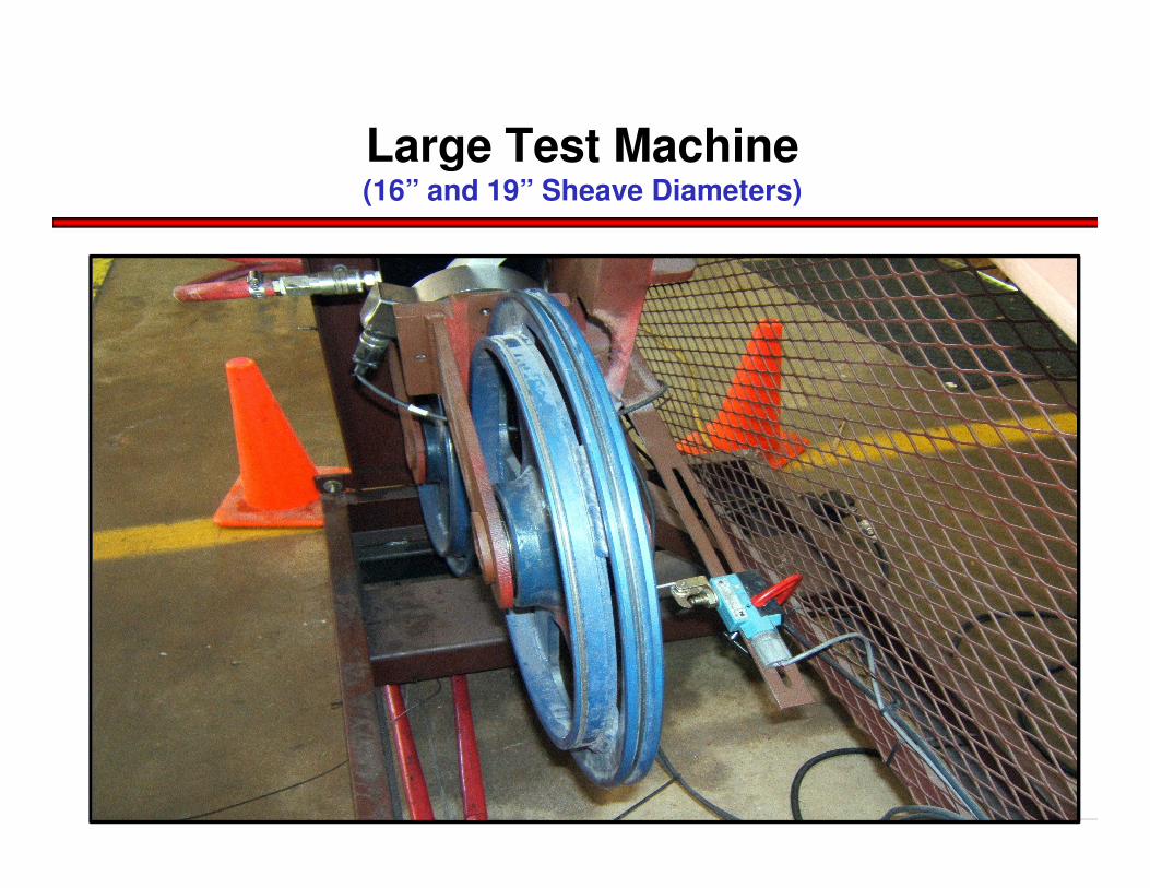
Large Test Machine(16” and 19” Sheave Diameters)

Large Test Machine(Spilt-Drum Used for Testing)
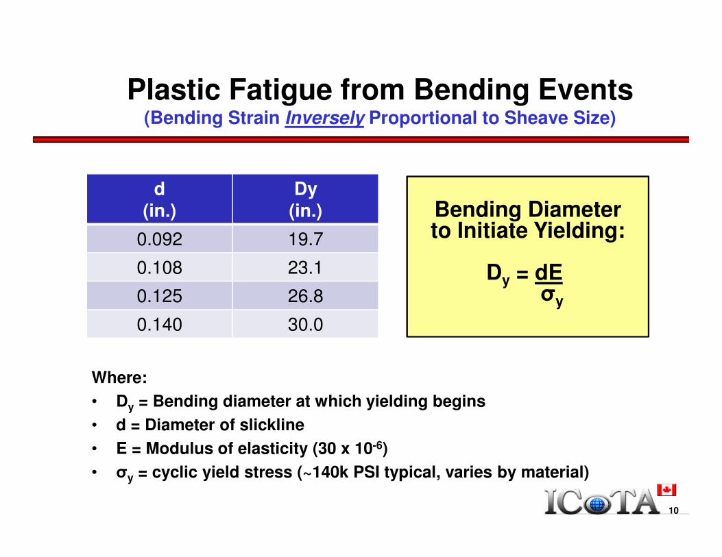
Plastic Fatigue from Bending Events(Bending Strain Inversely Proportional to Sheave Size)
Where:
• Dy = Bending diameter at which yielding begins
• d = Diameter of slickline
• E = Modulus of elasticity (30 x 10-6)
• σy = cyclic yield stress (~140k PSI typical, varies by material)
10
d(in.)
Dy(in.)
0.092 19.7
0.108 23.1
0.125 26.8
0.140 30.0
Bending Diameter to Initiate Yielding:
Dy = dEσy
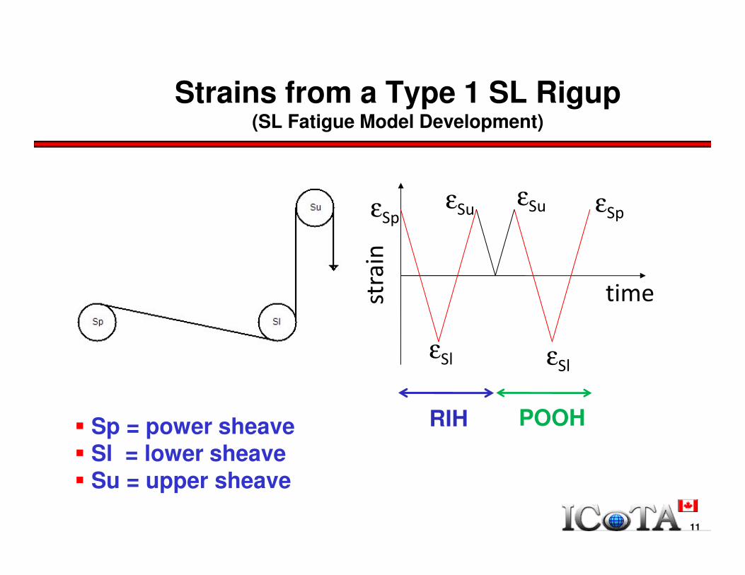
Strains from a Type 1 SL Rigup(SL Fatigue Model Development)
εSp
εSl
εSu εSp
εSl
εSu
time
� Sp = power sheave� Sl = lower sheave� Su = upper sheave
RIH POOH
strain
11
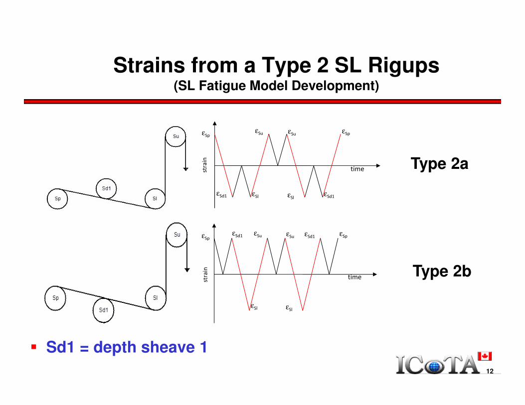
Strains from a Type 2 SL Rigups(SL Fatigue Model Development)
εSp
εSd1
εSu εSp
εSl
εSu
time
εSl εSd1
εSpεSd1 εSu εSp
εSl
εSu
time
εSl
εSd1
� Sd1 = depth sheave 1
Type 2a
Type 2b
strain
strain
12

� Sd2 = depth sheave 2
Type 3a
Type 3b
εSp
εSd2
εSu
εSl
εSu
time
εSlεSd1
εSp
εSd1εSd2
εSp
εSd2εSu
εSl
εSu
time
εSl
εSd1 εSp
εSd1εSd2
Strains from a Type 3 SL Rigups(SL Fatigue Model Development)
13

Model Results / Tension = 0(SL Fatigue Model Development)
14

Model Results / Tension = 2,000 lbs(SL Fatigue Model Development)
Corrosion / Tracked Fatigue De-Rating(Portable Slickline Fatigue Tester)
• Portable SL Fatigue Test Machine
− Wellsite use
• Rapid Testing of Short SL Samples
− Rotation of SL sample imparts bending strain
− Repeatable results
• Determine Life Reduction Due to Corrosion
− From tests of actual SL being ran in the field
16

Corrosion Life Reduction
• Maximum Corrosion @ Downhole End:
− Hottest corrosive wellbore fluids
− Longest period of time in well
− Exposure to atmosphere when on drum
• Corrosion Testing
− Samples taken from downhole end during life of SL
− Test samples in portable tester
− Compare test results to SL fatigue model
− If worse, add a corrosion factor to fatigue results
17
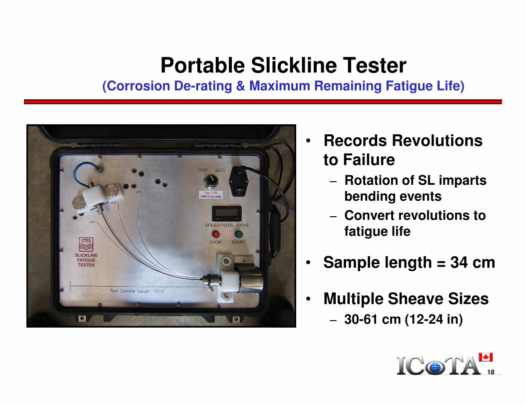
Portable Slickline Tester (Corrosion De-rating & Maximum Remaining Fatigue Life)
• Records Revolutions to Failure
− Rotation of SL imparts bending events
− Convert revolutions to fatigue life
• Sample length = 34 cm
• Multiple Sheave Sizes
− 30-61 cm (12-24 in)
18
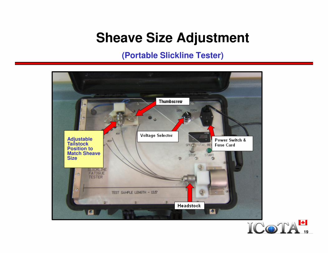
Sheave Size Adjustment(Portable Slickline Tester)
19
Adjustable Tailstock Position to Match Sheave Size
11
12
13
14
15
16
17
18
19
20
21
22
23
24
25
0 2,000 4,000 6,000 8,000 10,000
Full Reversals to Failure = Trips * 2
Ben
din
g D
iam
ete
r
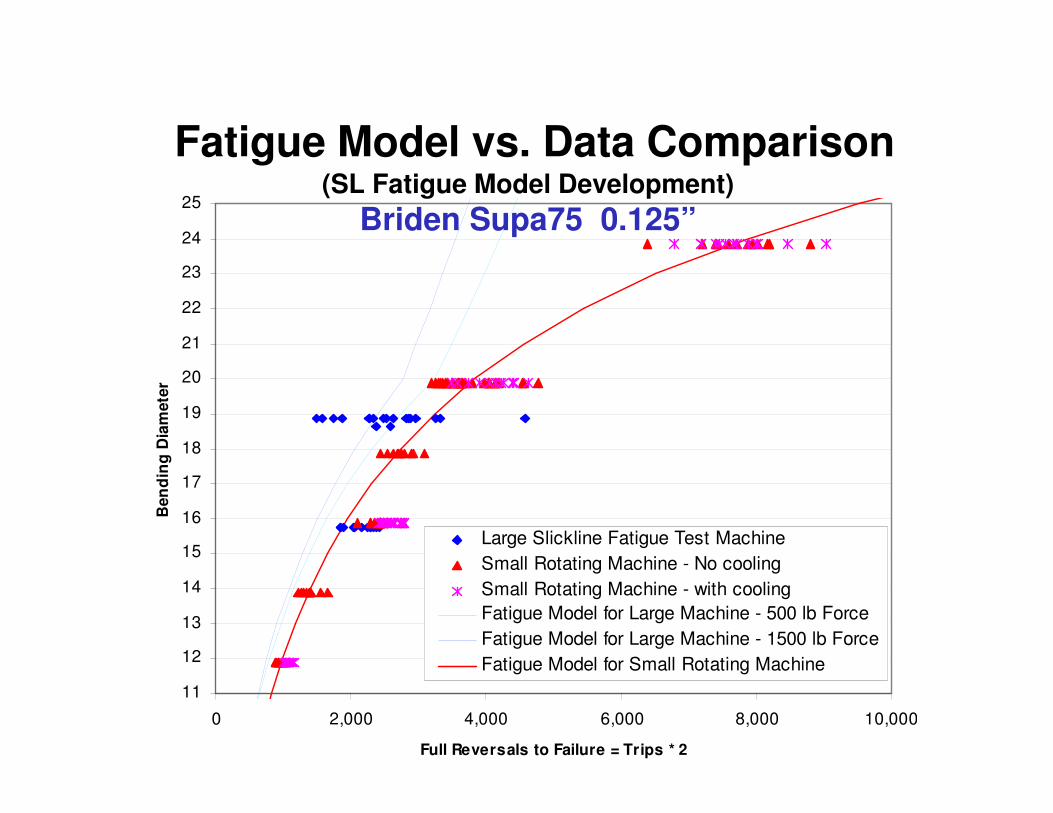
Large Slickline Fatigue Test Machine
Small Rotating Machine - No cooling
Small Rotating Machine - with cooling
Fatigue Model for Large Machine - 500 lb Force
Fatigue Model for Large Machine - 1500 lb Force
Fatigue Model for Small Rotating Machine
Fatigue Model vs. Data Comparison(SL Fatigue Model Development)
Briden Supa75 0.125”
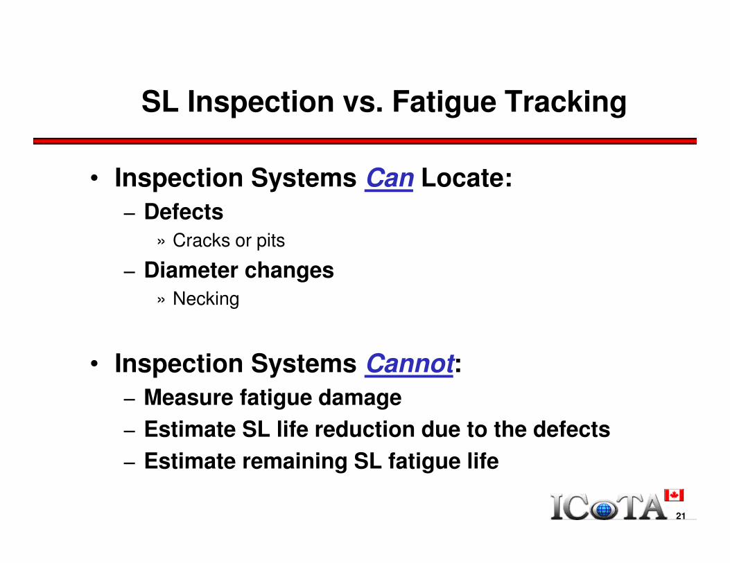
SL Inspection vs. Fatigue Tracking
• Inspection Systems Can Locate:
− Defects
» Cracks or pits
− Diameter changes
» Necking
• Inspection Systems Cannot:
− Measure fatigue damage
− Estimate SL life reduction due to the defects
− Estimate remaining SL fatigue life
21

Slickline Job Data(Example: Tension & Depth vs. Time)
22
Depth
Tension

% Fatigue Life Used Output(Example)
23
24
Slickline – Case History 1
Background• Sandvik 2RK66 0.108” slickline
• Slickline data acquisition system used to record field job data− Depth, tension, sheave size & configuration
• Field Data− 37 Individual job records (i.e. work on a single well) − Up to 7 downhole trips per well
• Slickline History− Time in service: 90 Days

25
Slickline(Case History 1)
Assumptions
• Fatigue Calculated as GD31MO 0.108” Slickline
• Several Jobs Not Recorded (<10% of total)
• Rig Up: Dual-wheeled Measuring Head− Upper & lower sheave wheels (‘Type 3’ rigup)
• 6 m Slickline Cut Off after Each Job (avg.)
• No Exposure to Corrosive Environments
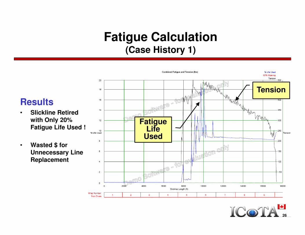
Fatigue Calculation(Case History 1)
Results• Slickline Retired
with Only 20% Fatigue Life Used !
• Wasted $ for Unnecessary Line Replacement
26
Tension
Fatigue Life
Used
Conclusion
• Slickline Fatigue Software
− Display/record job data
− Record line cuts & spooling events
− Real-time remaining fatigue life
− Can be utilized with DAS provided by numerous manufacturers
− Generates post-job customer reports
• Portable Fatigue Tester
− Test for corrosion
− Fatigue life de-rating
• Questions?
27


