

Oshikoto Region
Dundee Smelter Expansion Project
Environmental Impact Assessment
Groundwater and Surface Water Study
SLR Project No.: 733.04040.00010
October 2016
Report No.: 2016-WG28
Dundee Precious Metals
P. O. Box 80418
Tsumeb
NAMIBIA

DOCUMENT INFORMATION
Title Dundee Smelter Expansion Ground- and Surface Water Specialist Input to EIA
Project Manager Gwendal Madec
Project Manager e-mail [email protected]
Author Gwendal Madec, Jonathan Church, Piet Smit
Reviewer Arnold Bittner, Paul Klimczak
Client Dundee Precious Metals, Tsumeb
Date last printed 2017/02/27 03:48:00 PM
Date last saved 2017/01/10 06:24:00 PM
Comments
Keywords Impact Assessment, Smelter Expansion, Groundwater, Surface Water, Oshikoto
Project Number 733.04040.00010
Report Number 2016-WG-28
Status Final Draft
Issue Date October 2016
This report has been prepared by an SLR Group company with all reasonable skill, care and
diligence, taking into account the manpower and resources devoted to it by agreement with the
client. Information reported herein is based on the interpretation of data collected, which has
been accepted in good faith as being accurate and valid.
No warranties or guarantees are expressed or should be inferred by any third parties.
This report may not be relied upon by other parties without written consent from SLR.
SLR disclaims any responsibility to the Client and others in respect of any matters outside the
agreed scope of the work.

SLR Environmental Consulting (Namibia) (Pty) Ltd
SLR Ref. 733.04040.00010 Report No. 2016-WG-28
Dundee Smelter Expansion Ground- and Surface Water Specialist Input to EIA
October 2016
Page i
DUNDEE SMELTER EXPANSION GROUND- AND SURFACE WATER SPECIALIST INPUT TO EIA
CONTENTS
1 INTRODUCTION ...................................................................................................................... 2
1.1 BACKGROUND...................................................................................................................... 2
1.2 PURPOSE AND SCOPE OF WORK ........................................................................................... 3
2 GENERAL SETTINGS ............................................................................................................. 3
2.1 SITE DESCRIPTION ............................................................................................................... 3
2.2 CLIMATE .............................................................................................................................. 6
2.2.1 RAINFALL ......................................................................................................................................................... 6
2.2.2 EVAPORATION .................................................................................................................................................. 8
2.3 SOIL .................................................................................................................................... 9
2.4 GEOLOGY ............................................................................................................................ 9
2.4.1 STRATIGRAPHY............................................................................................................................................... 11
2.4.2 DPMT HYDROGEOLOGICAL SETTINGS. ............................................................................................................. 15
2.5 WATER ABSTRACTION ........................................................................................................ 18
2.6 SMELTER EXPANSION......................................................................................................... 18
3 DUNDEE SMELTER EXPANSION GROUNDWATER STUDY .............................................. 19
3.1 SCOPE OF WORK ............................................................................................................... 19
3.2 REVIEW ON GROUNDWATER MODELLING ............................................................................. 20
3.3 REVIEWING THE PREVIOUS GROUNDWATER REPORTS ......................................................... 20
3.3.1 PRELIMINARY ASSESSMENT OF THE CONTAMINATION RISKS TO THE GROUNDWATER REGIME AT THE TSUMEB
SMELTER, REPORT 2, DECEMBER 2009. ........................................................................................................... 20 3.3.2 NCS GROUNDWATER FLOW AND TRANSPORT MODEL, VERSION 1, JULY 2013..................................................... 21
3.3.3 NCS GROUNDWATER DATA REVIEW AND MONITORING, VERSION FINAL, MAY 2013 ............................................. 22
3.3.4 CLOSURE PLAN REPORT FOR DUNDEE PRECIOUS METALS TSUMEB, NOVEMBER 2013 ......................................... 24
3.3.5 TSUMEB WATER SUPPLY AND SMELTER STUDIES PHASE 4: SMELTER SINKHOLE RISK AND CONTAMINANT PLUME
MAPPING, DRAFT REPORT 1, VERSION 1, DECEMBER 2014 .................................................................................. 25 3.3.6 TSUMEB SMELTER GROUNDWATER MODEL UPDATE, REPORT 1, 04 MARCH 2016 ................................................ 28
3.3.7 REVIEW OF GROUNDWATER MONITORING ......................................................................................................... 31
3.4 GROUNDWATER QUALITY ................................................................................................... 32
3.5 CONCLUSIONS AND RECOMMENDATIONS ............................................................................. 38
4 DUNDEE SMELTER EXPANSION SURFACE WATER STUDY ............................................ 44
4.1 SCOPE OF WORK ............................................................................................................... 44
4.2 REGIONAL HYDROLOGY ...................................................................................................... 45
4.3 LOCAL HYDROLOGY ........................................................................................................... 45
4.4 PEAK FLOW ESTIMATION FOR LOCAL RUNOFF ..................................................................... 46
4.5 SURFACE WATER QUALITY ................................................................................................. 46
4.6 REVIEW OF STORM WATER MANAGEMENT........................................................................... 49
4.7 REVIEW OF SITE WATER BALANCE STUDIES ........................................................................ 55
4.7.1 GENERAL ....................................................................................................................................................... 55
4.7.2 PROCESS WATER ........................................................................................................................................... 55
4.7.3 WATER BALANCE CONCLUSIONS ...................................................................................................................... 56
SLR Environmental Consulting (Namibia) (Pty) Ltd
SLR Ref. 733.04040.00010 Report No. 2016-WG-28
Dundee Smelter Expansion Ground- and Surface Water Specialist Input to EIA
October 2016
Page ii
4.8 ENVIRONMENTAL IMPACTS FOR SURFACE WATER ................................................................ 57
5 GROUND- AND SURFACE WATER IMPACT ASSESSMENT .............................................. 58
5.1 GROUNDWATER IMPACT ASSESSMENT ................................................................................ 62
5.2 SURFACE WATER IMPACT ASSESSMENT .............................................................................. 65
5.3 CUMULATIVE IMPACT ASSESSMENT OF PROPOSED DUNDEE SMELTER EXPANSION ON GROUND- AND SURFACE WATER RESOURCES ................................................................................... 69
6 SUMMARY AND CONCLUSIONS ......................................................................................... 70
7 REFERENCES ....................................................................................................................... 73
8 APPENDICES ........................................................................................................................ 76

SLR Environmental Consulting (Namibia) (Pty) Ltd
SLR Ref. 733.04040.00010 Report No. 2016-WG-28
Dundee Smelter Expansion Ground- and Surface Water Specialist Input to EIA
October 2016
Page iii
LIST OF FIGURES
FIGURE 1: LOCATION OF SITE IN THE EASTERN OTAVI MOUNTAINLAND AREA .............................................. 4
FIGURE 2: GENERAL LAYOUT OF SITE SHOWING RELIEF ................................................................................... 5
FIGURE 3: GENERAL LAYOUT OF SITE SHOWING INFRASTRUCTURE .............................................................. 5
FIGURE 4: TSUMEB MONTHLY MEAN RAINFALL DISTRIBUTION ......................................................................... 6
FIGURE 5: TSUMEB ANNUAL RAINFALL ................................................................................................................. 7
FIGURE 6: TSUMEB MET. OFFICE SITE RAINFALL EXCEEDANCE ....................................................................... 8
FIGURE 7: MEAN MONTHLY EVAPORATION AND RAINFALL FOR TSUMEB AREA ............................................ 9
FIGURE 8: LOCATION OF THE PAN AFRICAN BELTS (MODIFIED AFTER MILLER 1983A) ............................... 10
FIGURE 9: LOCATION OF THE OTAVI MOUNTAINLAND (OML) ........................................................................... 11
FIGURE 10: PRE-KALAHARI GEOLOGY OF THE OTAVI MOUNTAIN LAND (AFTER TCL, DIGITAL DATA) ......... 14
FIGURE 11: LOCAL GEOLOGY AROUND THE DPMT SITE, WITH SW-NE CROSS SECTION (GCS: 2013) ......... 15
FIGURE 12: REGIONAL GROUNDWATER FLOW DIRECTION (GKW CONSULT / BICON 2003) .......................... 16
FIGURE 13: CONCEPTUAL DPMT GROUNDWATER MODEL (SOURCE: GCS, 2013) .......................................... 17
FIGURE 14: HYDROSTRATIGRAPHY (MUKENDWA, 2009)..................................................................................... 17
FIGURE 15: A MAP INDICATING THE PIEZOMETRIC HEAD IN THE SMELTER AREA BASED ON WATER LEVEL MEASUREMENT REPORTED IN MAY 2013 (GCS. 2013). .................................................................... 23
FIGURE 16: DOLOMITE STABILITY RISK AREAS BASED ON GEOPHYSICAL DATA INTERPRETATION (GCS, 2014) ....................................................................................................................................................... 27
FIGURE 17: A MAP DEPICTING THE EXTENT OF THE MODELLED ARSENIC PLUME BY 2038 WITH NO REMEDIATION BEING UNDERTAKEN. (GCS, 2016) ............................................................................ 30
FIGURE 18: MAP INDICATING ARSENIC CONCENTRATIONS IN GROUNDWATER IN THE WIDER TSUMEB AREA (GKW CONSULT / BICON 2003) .................................................................................................. 33
FIGURE 19: MAP INDICATING THE LOCATION OF THE MONITORING BOREHOLES ON THE SMELTER SITE. 34
FIGURE 20: A MAP INDICATING THE ARSENIC CONCENTRATIONS IN THE MONITORING BOREHOLES ON SITE FOR JULY 2015. ............................................................................................................................ 35
FIGURE 21: A TIME SERIES GRAPH INDICATING THE ARSENIC CONCENTRATION MEASURED IN THE SITE BOREHOLES SINCE FEBRUARY 2012 ................................................................................................. 37
FIGURE 22: SMELTER SITE SHOWING LOCAL HYDROLOGY ............................................................................... 45
FIGURE 23: LOCAL SURFACE WATER SAMPLING LOCATIONS ........................................................................... 47
FIGURE 24: ARSENIC RESULTS FROM SURFACE WATER SAMPLING OCTOBER 2015 .................................... 48
FIGURE 25: JORDAN RIVER SAMPLING LOCATIONS ............................................................................................ 49
FIGURE 26 : PROPOSED CLEAN WATER CUTOFF CHANNEL (FROM AURECON 2013 REPORT) ...................... 51
FIGURE 27 : PLANNED STORM WATER SYSTEM (FROM AURECON 2013 REPORT) .......................................... 51
FIGURE 28 : CURRENT STORMWATER LAYOUT (FROM GOLDER ASSOCIATES ESIA REPORT 2013)............. 52
FIGURE 29: LOCAL STORM WATER PONDING LOCATIONS (FROM AURECON 2013 REPORT) ....................... 53
FIGURE 30: LOCATION OF SITE WATER RELATED INFRASTRUCTURE .............................................................. 58
FIGURE 31: PROCESS FOR EFFLUENT PERMIT APPLICATION ........................................................................... 71
LIST OF TABLES
TABLE 1: TSUMEB AREA MONTHLY RAINFALL AND EVAPORATION DATA ........................................................... 8
TABLE 2: GEOLOGY AND STRATIGRAPHY OF THE AREA ..................................................................................... 12
TABLE 3: LOCATION OF GROUNDWATER SAMPLING POINTS ............................................................................. 34
TABLE 4: ANALYSES RESULTS FOR THE SAMPLES TAKEN IN JULY 2015 FROM BOREHOLES ON THE SMELTER SITE. ......................................................................................................................................... 36
TABLE 5: LIST OF RECOMMENDATIONS MADE IN VARIOUS GROUNDWATER REPORTS FOR DPMT SINCE 2009............................................................................................................................................................ 39

SLR Environmental Consulting (Namibia) (Pty) Ltd
SLR Ref. 733.04040.00010 Report No. 2016-WG-28
Dundee Smelter Expansion Ground- and Surface Water Specialist Input to EIA
October 2016
Page iv
TABLE 6: LIST OF RECOMMENDATIONS MADE IN AURECON STORM WATER REPORT (2013) ....................... 54
TABLE 7: SUMMARY OF GROUNDWATER IMPACTS FROM GOLDER ESIA 2013 ................................................ 59
TABLE 8: SUMMARY OF SURFACE WATER IMPACTS FROM GOLDER ESIA 2013 .............................................. 59
TABLE 9 : CRITERIA FOR ASSESSING IMPACTS ..................................................................................................... 61
TABLE 10 : IMPACT OF PROPOSED DUNDEE SMELTER EXPANSION ON GROUNDWATER QUANTITY ........ 63
TABLE 11 : IMPACT OF PROPOSED DUNDEE SMELTER EXPANSION ON GROUNDWATER QUALITY ........... 64
TABLE 12 : IMPACT OF PROPOSED DUNDEE SMELTER EXPANSION ON SURFACE WATER RUNOFF ......... 67
TABLE 13 : IMPACT OF PROPOSED DUNDEE SMELTER EXPANSION ON SURFACE WATER POLLUTION .... 68
LIST OF APPENDICES
APPENDIX 1: WATER QUALITY GUIDELINES (DWAF, 1988) ....................................................................................... 76
APPENDIX 2: MET. OFFICE RAINFALL DATA FOR TSUMEB AREA (MM) ................................................................... 78
APPENDIX 3: DPMT WATER QUALITY DATA (OCTOBER 2015) .................................................................................. 83
APPENDIX 4: JORDAN RIVER WATER QUALITY DATA (JUNE 2016) .......................................................................... 84

SLR Environmental Consulting (Namibia) (Pty) Ltd
SLR Ref. 733.04040.00010 Report No. 2016-WG-28
Dundee Smelter Expansion Ground- and Surface Water Specialist Input to EIA
October 2016
Page i
ACRONYMS AND ABBREVIATIONS
Below a list of acronyms and abbreviations used in this report.
Acronyms / Abbreviations
Definition
BH Borehole
DPMT Dundee Precious Metals Tsumeb
DWAF Department of Water Affairs and Forestry
EBRD European Bank for Reconstruction and Development
EIA Environmental Impact Assessment
ESIA Environmental and Social Impact Assessment
GCS Groundwater Consulting Services
GRN Government of the Republic of Namibia
GROWAS Namibian National Groundwater Database, Dept. of Water Affairs and Forestry
km Kilometre
km2 Square kilometres
m amsl Metres above mean sea level
m bgl Metres below ground level
mm Millimetres
m3/h Cubic metres per hour
m3/d Cubic metres per day
Ml/day Million litres per day (Thousand cubic metres per day)
NASA National Aeronautics and Space Administration
NCS Namibia Custom Smelters
PR Performance Requirement
QA / QC Quality Assurance / Quality Control
RWL Rest Water Level
SLR SLR Environmental Consulting (Namibia) (Pty) Ltd
SRTM Shuttle Radar Topography Mission
TGWS Tsumeb Groundwater Study
TSF Tailings Storage Facility

SLR Environmental Consulting (Namibia) (Pty) Ltd
SLR Ref. 733.04040.00010 Report No. 2016-WG-28
Dundee Smelter Expansion Ground- and Surface Water Specialist Input to EIA
October 2016
Page 2
DUNDEE SMELTER EXPANSION GROUND- AND SURFACE WATER SPECIALIST INPUT TO EIA
1 INTRODUCTION
1.1 BACKGROUND
Dundee Precious Metals Tsumeb Ltd (DPMT) has applied for an Environmental Impact
Assessment to be carried out for the smelter expansion in the Oshikoto Region of Namibia.
The site is in the Tsumeb Townlands, on an existing site which has been operating a smelter
for many years, and where various metals have been mined historically, which has had
significant impacts on the environment. One of these impacts is the pollution of surface water
and groundwater. In 2012 DPMT embarked on an intensive programme of upgrading the
smelter operations to increase production and to improve operational efficiency and
environmental performance. For this reason a new Environmental Management Plan is being
developed.
SLR`s task is now to review and comment on various groundwater and surface water
documentation provided by the client and produce a groundwater and surface water impact
assessment for the planned smelter expansion.
The Client requested that where relevant European Bank for Reconstruction and
Development (EBRD) Performance Requirements should be taken into account during this
study. The main Performance Requirement with relevance to this study is EBRD
Performance Requirement 3 - Resource Efficiency and Pollution Prevention and Control
(“PR3”). From PR3 Section 8 (Pollution Prevention and Control), the following is noted;
“The client’s environmental and social assessment process will determine the appropriate
pollution prevention and control methods, technologies and practices (“techniques”) to be
applied to the project. The assessment will take into consideration the characteristics of the
facilities and operations that are part of the project, the project’s geographical location and
local ambient environmental conditions. The assessment process will identify technically and
financially feasible and cost-effective pollution prevention and control techniques that are
best suited to avoid or minimise adverse impacts on human health and the environment. The
techniques applied to the project will favour the prevention or avoidance of risks and impacts
over minimisation and reduction, in line with the mitigation hierarchy approach and consistent
with GIP, and will be appropriate to the nature and scale of the project’s adverse impacts and
issues.”

SLR Environmental Consulting (Namibia) (Pty) Ltd
SLR Ref. 733.04040.00010 Report No. 2016-WG-28
Dundee Smelter Expansion Ground- and Surface Water Specialist Input to EIA
October 2016
Page 3
The current study by SLR is an important part of this environmental assessment process,
which will produce recommendations for pollution prevention and control methods as part of
the mitigation measures discussed in Sections 5 and 6 of this report. .
1.2 PURPOSE AND SCOPE OF WORK
The report presents a ground- and surface water study for the proposed Tsumeb smelter
expansions located at the Dundee Precious Metals site in Tsumeb.
The structure of the ground- and surface water report is as follows:
• Section 1 presents the introduction;
• In Section 2 general settings of the project area are briefly stated and the proposed
development described;
• Section 3 presents the groundwater study including a description of the hydrogeological
baseline conditions of the focus and surrounding areas, review and comment on various
documentation provided by the client, review of groundwater monitoring network and
sampling procedures, review of the latest groundwater model for the site and also
recommendations for groundwater management;
• Section 4 presents the surface water study including a description of the regional and
local baseline hydrology, a review of the site water balance studies, the storm water
management plan and the surface water management;
• Section 5 presents the impact assessments for groundwater and surface water
considering the cumulative impacts (including the planned expansions);
• Section 6 presents the summary and conclusions.
2 GENERAL SETTINGS
2.1 SITE DESCRIPTION
Figure 1 shows the smelter site location in Tsumeb and the eastern Otavi Mountainland
area. The elevation at the site is approximately 1 270 m amsl, and the area slopes gently in a
north-westerly direction towards the Kalahari Basin in the north.

SLR Environmental Consulting (Namibia) (Pty) Ltd
SLR Ref. 733.04040.00010 Report No. 2016-WG-28
Dundee Smelter Expansion Ground- and Surface Water Specialist Input to EIA
October 2016
Page 4
FIGURE 1: LOCATION OF SITE IN THE EASTERN OTAVI MOUNTAINLAND AREA
Figure 2 shows the site with elevation data from SRTM (Shuttle Radar Topography Mission)
supplied by the NASA. From this it can be seen that the smelter site is located within a valley
running in a south-east to north-west direction just to the north of the main Tsumeb town.
Figure 3 shows some of the main processing infrastructure around the site, along with the
main drainage lines through the site.

SLR Environmental Consulting (Namibia) (Pty) Ltd
SLR Ref. 733.04040.00010 Report No. 2016-WG-28
Dundee Smelter Expansion Ground- and Surface Water Specialist Input to EIA
October 2016
Page 5
FIGURE 2: GENERAL LAYOUT OF SITE SHOWING RELIEF
FIGURE 3: GENERAL LAYOUT OF SITE SHOWING INFRASTRUCTURE

SLR Environmental Consulting (Namibia) (Pty) Ltd
SLR Ref. 733.04040.00010 Report No. 2016-WG-28
Dundee Smelter Expansion Ground- and Surface Water Specialist Input to EIA
October 2016
Page 6
2.2 CLIMATE
The ATLAS OF NAMIBIA, 2002 shows the study area to have an annual average temperature
of 20 to 22°C, with an average maximum of 32 to 34°C during the hottest month (December)
and an average minimum of 6 to 8°C during the coldest month (July), with an average of 1 to
5 frost days per year.
2.2.1 RAINFALL
The nearest long and reliable rainfall record to the smelter site is from Tsumeb
Meteorological Station, which is less than 1 km from the site.
Tsumeb has a Meteorological Office rainfall record of approximately 90 years length
(1913/14 to present with some lost data, see Appendix 2), which provides a fairly accurate
long-term average. Rainfall data has been analysed for the hydrological year, which runs
from 1st October to 30th September, hence years are shown as 1913/14, being data for
October 1913 through to September 1914. The average monthly rainfall values are shown in
Table 1 and Figure 4 which shows that the majority of rainfall (88 %) falls between November
and March. The mean annual precipitation (MAP) is 503 mm and there are two months of
average rainfall greater than 100 mm (January and February), with the highest monthly
rainfall being 370.6 mm recorded in February 1944. The highest annual rainfall was
1,006 mm recorded in 1943/44 and there have been ten years when the annual rainfall was
over 700 mm. Annual rainfall data recorded at Tsumeb is shown graphically in Figure 5.
FIGURE 4: TSUMEB MONTHLY MEAN RAINFALL DISTRIBUTION

SLR Environmental Consulting (Namibia) (Pty) Ltd
SLR Ref. 733.04040.00010 Report No. 2016-WG-28
Dundee Smelter Expansion Ground- and Surface Water Specialist Input to EIA
October 2016
Page 7
FIGURE 5: TSUMEB ANNUAL RAINFALL
The rainfall data (1913/14 to 2008/09) for the Tsumeb Met Office rain gauge was analysed
for exceedance using the Cunane Plotting Equation Pt = (M-0.4) / (N+0.2) where ;
PT = Probability of Exceedance,
N = Total Number of Observations,
M = Ranked Number of Observed Value,
with the resulting rainfall exceedance for the station shown in Figure 6.
Rainfall seasons with lost data in the months between November and March were
highlighted and excluded from the analysis, with the exception of 1933/34 which was a
significantly wet year and is included to allow storm water calculations to be more
conservative.
From this it can be seen that in Tsumeb there is an 80 % probability that the annual rainfall
will be approximately 370 mm, a 50 % probability that the annual rainfall will be 480 mm and
a 20% probability that the annual rainfall will be approximately 590 mm.

SLR Environmental Consulting (Namibia) (Pty) Ltd
SLR Ref. 733.04040.00010 Report No. 2016-WG-28
Dundee Smelter Expansion Ground- and Surface Water Specialist Input to EIA
October 2016
Page 8
FIGURE 6: TSUMEB MET. OFFICE SITE RAINFALL EXCEEDANCE
Rainfall is generally from storms producing short cloud-bursts of low to high intensity, but as
the site is located in the karst area where infiltration is relatively high, reduced surface runoff
volumes should be expected.
2.2.2 EVAPORATION
Calculated from Namibian Meteorological Office (Met. Office) Class-A evaporation pan data,
the following evaporation data was taken from the Department of Water Affairs Evaporation
Map Report (1988).
The A-pan evaporation values for Tsumeb were then converted to open water values
(evaporation from a Class-A evaporation pan is higher than from an open body of water) to
compile an estimated evaporation distribution for the Tsumeb area. The estimated open
water evaporation values are shown in Table 1 and in Figure 7.
TABLE 1: TSUMEB AREA MONTHLY RAINFALL AND EVAPORATION DATA Tsumeb Mean Annual
Evaporation Oct Nov Dec Jan Feb Mar Apr May Jun Jul Aug Sep Total
Monthly Percentage 11.9 11.2 11.8 10.7 8.0 7.3 6.2 5.5 4.9 5.4 7.3 9.8 100
A-Pan Evaporation (mm) 249.2 234.5 247.1 224.1 167.5 152.9 129.8 115.2 102.6 113.1 152.9 205.2 2 094
Open Water Evaporation (mm) 174 164 173 179 134 122 104 92 82 90 122 164 1 602
Tsumeb Mean Monthly Rain (mm) 20.4 53.4 77.3 118.3 118.6 76.2 32.1 4.5 0.4 0.0 0.1 2.5 504
As can be seen from these figures the monthly evaporation for all months is higher than the
rainfall, indicating that the Tsumeb area is a water negative area, meaning that there is an

SLR Environmental Consulting (Namibia) (Pty) Ltd
SLR Ref. 733.04040.00010 Report No. 2016-WG-28
Dundee Smelter Expansion Ground- and Surface Water Specialist Input to EIA
October 2016
Page 9
overall deficit in the available water, especially during the months from April to November,
when there is little or no rainfall. However, from Figure 7 it can be seen that in January and
February the mean monthly rainfall and evaporation are much closer, suggesting that the
area becomes more of a water neutral area, where rainfall nearly matches evaporation.
FIGURE 7: MEAN MONTHLY EVAPORATION AND RAINFALL FOR TSUMEB AREA
2.3 SOIL
Data on dominant soils was sourced from the Atlas of Namibia (Mendelsohn 2002), i.e. the
information presented is not based on a field survey.
Dominant soils prevailing in the Tsumeb area rock outcrops (representing the karst) with a
band of Chromic Luvisols running approximately east to west through the area. Chromic
refers to soils with bright colours and luvisols are a soil unit which only occurs (in Namibia) in
two small areas west of Grootfontein, which have good water holding capacity and are well
drained with a porous and aerated structure. Luvisols typically comprise an accumulation of
clay that has settled some depth below the surface.
2.4 GEOLOGY
The period 900-950Ma was marked by extensive continental fragmentation with
geosynclinals deposition in a major Late Proterozoic – Early Paleozoic tectono-thermal event
referred as Pan-African event (Master, 1991). Downward flexing of the craton margins

SLR Environmental Consulting (Namibia) (Pty) Ltd
SLR Ref. 733.04040.00010 Report No. 2016-WG-28
Dundee Smelter Expansion Ground- and Surface Water Specialist Input to EIA
October 2016
Page 10
produced extensive intra-cratonic foreland basins (Thomas & al, 1993). The late Proterozoic
to Early Palaeozoic Damara belt forms part of the Pan-African mobile system belt, which
surrounds and bisects the African continent (Martin 1983, Miller 1983a),
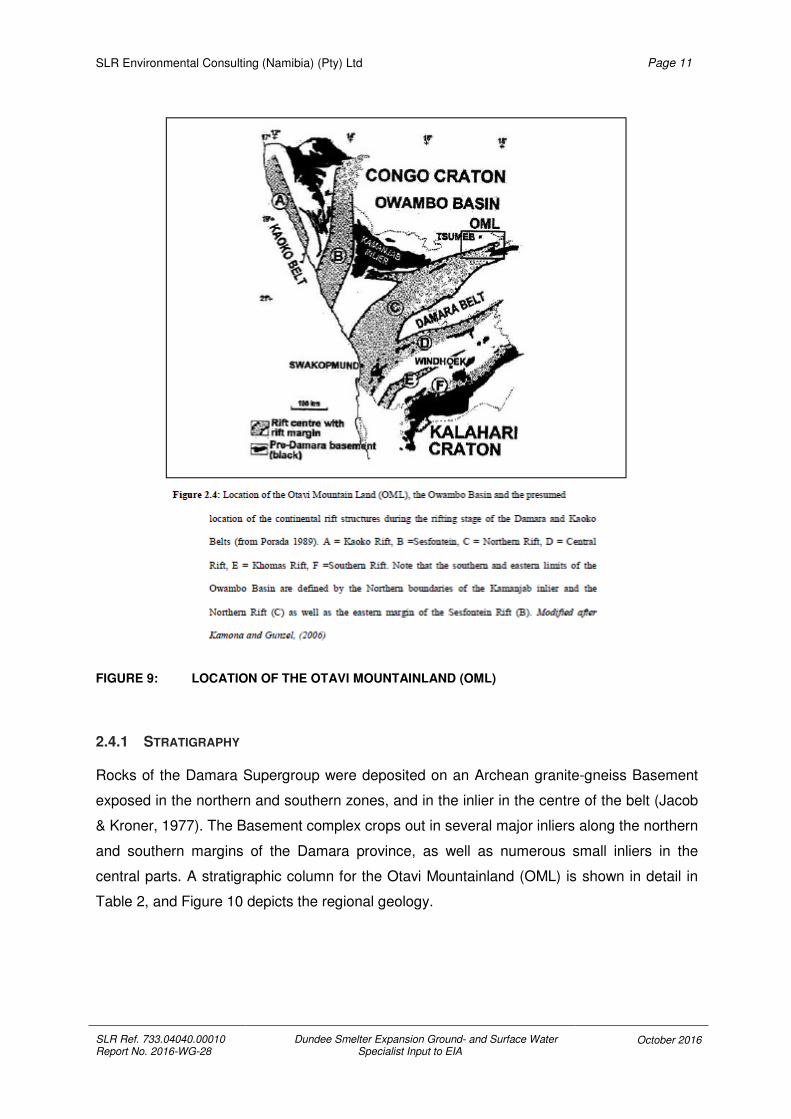
FIGURE 8: LOCATION OF THE PAN AFRICAN BELTS (MODIFIED AFTER MILLER 1983A)
The NE-trending Pan-African Damara Belt is 400 km wide and is located between the Congo
and the Kalahari Cratons in the South West region of Southern Africa (Figure 8).
The Damara Supergroup consists of a north east trending intracontinental arm and a north
south trending coastal arm with a present outcrop width in Namibia of 150 km. The triple
junction between the two arms is located off the coast near Swakopmund (Miller, 1983c).
Evolution of the belt involves a complex history which includes rifting, spreading,
convergence and collision of Kalahari and Congo Cratons. In addition to this, deformation,
metamorphism and magmatism accompanied the collision. Subsequently the belt underwent
episodes of continental rifting, ocean floor spreading, glaciation, subduction, collision and
metamorphism over a time span of about 250Ma (Figure 9).
SLR Environmental Consulting (Namibia) (Pty) Ltd
SLR Ref. 733.04040.00010 Report No. 2016-WG-28
Dundee Smelter Expansion Ground- and Surface Water Specialist Input to EIA
October 2016
Page 11
FIGURE 9: LOCATION OF THE OTAVI MOUNTAINLAND (OML)
2.4.1 STRATIGRAPHY
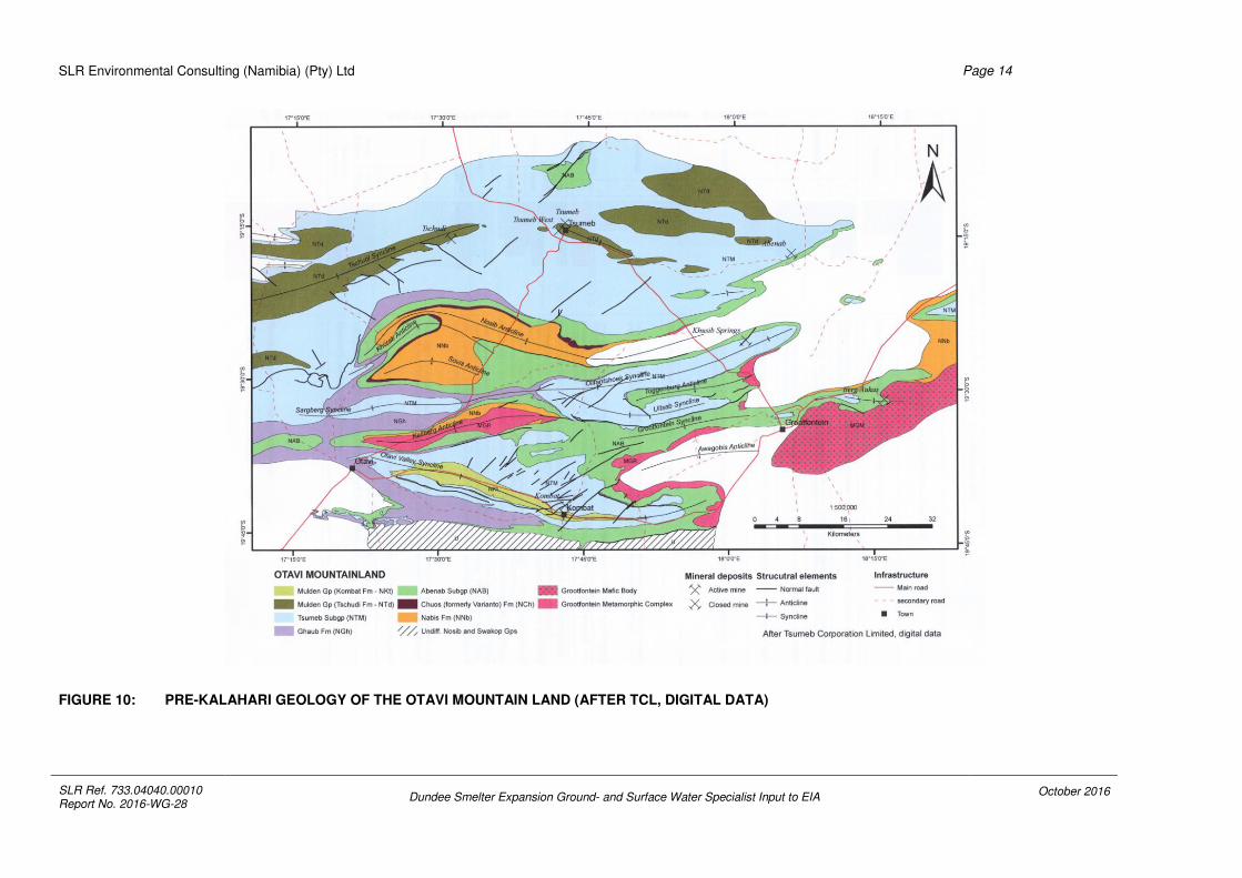
Rocks of the Damara Supergroup were deposited on an Archean granite-gneiss Basement
exposed in the northern and southern zones, and in the inlier in the centre of the belt (Jacob
& Kroner, 1977). The Basement complex crops out in several major inliers along the northern
and southern margins of the Damara province, as well as numerous small inliers in the
central parts. A stratigraphic column for the Otavi Mountainland (OML) is shown in detail in
Table 2, and Figure 10 depicts the regional geology.

SLR Environmental Consulting (Namibia) (Pty) Ltd
SLR Ref. 733.04040.00010 Report No. 2016-WG-28
Dundee Smelter Expansion Ground- and Surface Water Specialist Input to EIA
October 2016
Page 12
TABLE 2: GEOLOGY AND STRATIGRAPHY OF THE AREA
(Stratigraphic Column for the Otavi Mountainland, revised after Hoffmann and Prave (2008))
The Nosib Group unconformably overlies the Basement Complex. It consists of the Nabis,
Chuos, Berg Aukas and Gauss formations. The environment of deposition progressively
developed from predominantly fluvial to marine when finer grained shales were deposited
(Kamona & Gunzel, 2006).
The Otavi Group consists of Abenab and the Tsumeb subgroups which are unconformably
overlying the Nosib Group and the Basement Complex (Hedberg, 1979). The latest, the
SUPER
GROUP

SLR Environmental Consulting (Namibia) (Pty) Ltd
SLR Ref. 733.04040.00010 Report No. 2016-WG-28
Dundee Smelter Expansion Ground- and Surface Water Specialist Input to EIA
October 2016
Page 13
Tsumeb Subgroup, is subdivided into 8 litho-zones (T1 to T8) from the clastic Ghaub
Formation to the carbonate dominant Maieberg, Elandshoek as well as the Hüttenberg
Formations.
The Ghaub Formation, referred to as T1, is a glacio-marine tillite with lenses of dolomite
and schist.
The Maieberg Formation is a platform slope, deep water deposit and overlies the Ghaub
Formation. The lower Maieberg Formation (T2) consists of slump brecciated and laminated
carbonate and argillaceous sediments. The upper Maieberg Formation (T3) comprises
bedded and finely laminated carbonates.
The Elandshoek Formation conformably overlies the Maieberg Formation. It covers most of
the northern limb of the Otavi Valley north of Kombat Mine. The lower Elandshoek Formation
(T4) comprises of massive dolomite and is responsible for the rugged geomorphologic terrain
of the northern limb of the Otavi Valley. The brecciation is generally intensive and therefore
T4 is regarded as an important aquifer (Van der Merwe, 1986). The upper Elandshoek
Formation (T5) is fairly thin and not easily distinguishable from T4.
The Hüttenberg Formation marks the change from the deep sea environment observed in
the Elandshoek Formation to shallow lagoon shelves. It consists of a grey bedded basal
dolomite, stromatolite rich (T6), overlain by two upper units, a massive dark and bedded
dolomite with chert and with phyllite (T7) and T8 is marked by pisolite and oolite.
The Mulden Group is characterised by the Kombat Formation in the southern part of the
OML, which consists of a siliciclastic molasses (poorly graded phyllite, arkose, argillite and
siltstone) deposited syn-tectonically during the early stage of the Damara Orogeny, and the
Tschudi Formation (Arkose and feldspathic sandstone) in the northern part of the OML, and
is separated from the Tsumeb Subgroup by an angular disconformity.
SLR Environmental Consulting (Namibia) (Pty) Ltd
SLR Ref. 733.04040.00010 Report No. 2016-WG-28
Dundee Smelter Expansion Ground- and Surface Water Specialist Input to EIA October 2016
Page 14
FIGURE 10: PRE-KALAHARI GEOLOGY OF THE OTAVI MOUNTAIN LAND (AFTER TCL, DIGITAL DATA)

SLR Environmental Consulting (Namibia) (Pty) Ltd
SLR Ref. 733.04040.00010 Report No. 2016-WG-28
Dundee Smelter Expansion Ground- and Surface Water Specialist Input to EIA
October 2016
Page 15
2.4.2 DPMT HYDROGEOLOGICAL SETTINGS.
The town of Tsumeb lies on the northern edge of the OML and is characterised by the
sandstones of the Tschudi Formation (Mulden Group) and extends in an east-west direction.
The Tsumeb Smelter is located on the T5 (Elandshoek Formation) and T6 (Hüttenberg
Formation) lithozones, in an ESE-WNW sloping valley formed as part of an anticlinal
structure. The groundwater is expected to move in fold axes, pressure relief joints, faults or
on lithological contact zones (Figure 11).
FIGURE 11: LOCAL GEOLOGY AROUND THE DPMT SITE, WITH SW-NE CROSS SECTION (GCS: 2013)
The groundwater generally flows in a northerly direction within the highly permeable
(k=1.08 m/d, (GCS 2013)) dolomites of the Hüttenberg Formation (Figure 13). The dolomitic
hills consist of the T7 (Hüttenberg Formation) litho-zone, highly karstified and considered as
an aquifer (Figure 13) as well as the T6 litho-zone (Figure 14) whereby giving only one K
(Hydraulic conductivity) value might not be ideal; as a matter of fact the hills are a recharge
zone for the groundwater.

SLR Environmental Consulting (Namibia) (Pty) Ltd
SLR Ref. 733.04040.00010 Report No. 2016-WG-28
Dundee Smelter Expansion Ground- and Surface Water Specialist Input to EIA October 2016
Page 16
FIGURE 12: REGIONAL GROUNDWATER FLOW DIRECTION (GKW CONSULT / BICON 2003)

SLR Environmental Consulting (Namibia) (Pty) Ltd
SLR Ref. 733.04040.00010 Report No. 2016-WG-28
Dundee Smelter Expansion Ground- and Surface Water Specialist Input to EIA
October 2016
Page 17
FIGURE 13: CONCEPTUAL DPMT GROUNDWATER MODEL (SOURCE: GCS, 2013)
FIGURE 14: HYDROSTRATIGRAPHY (MUKENDWA, 2009)
SLR Environmental Consulting (Namibia) (Pty) Ltd
SLR Ref. 733.04040.00010 Report No. 2016-WG-28
Dundee Smelter Expansion Ground- and Surface Water Specialist Input to EIA
October 2016
Page 18
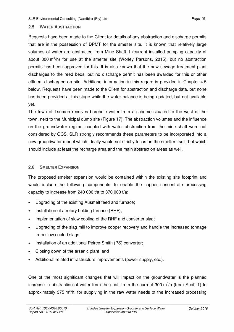
2.5 WATER ABSTRACTION
Requests have been made to the Client for details of any abstraction and discharge permits
that are in the possession of DPMT for the smelter site. It is known that relatively large
volumes of water are abstracted from Mine Shaft 1 (current installed pumping capacity of
about 300 m3/h) for use at the smelter site (Worley Parsons, 2015), but no abstraction
permits has been approved for this. It is also known that the new sewage treatment plant
discharges to the reed beds, but no discharge permit has been awarded for this or other
effluent discharged on site. Additional information in this regard is provided in Chapter 4.5
below. Requests have been made to the Client for abstraction and discharge data, but none
has been provided at this stage while the water balance is being updated, but not available
yet.
The town of Tsumeb receives borehole water from a scheme situated to the west of the
town, next to the Municipal dump site (Figure 17). The abstraction volumes and the influence
on the groundwater regime, coupled with water abstraction from the mine shaft were not
considered by GCS. SLR strongly recommends these parameters to be incorporated into a
new groundwater model which ideally would not strictly focus on the smelter itself, but which
should include at least the recharge area and the main abstraction areas as well.
2.6 SMELTER EXPANSION
The proposed smelter expansion would be contained within the existing site footprint and
would include the following components, to enable the copper concentrate processing
capacity to increase from 240 000 t/a to 370 000 t/a:
• Upgrading of the existing Ausmelt feed and furnace;
• Installation of a rotary holding furnace (RHF);
• Implementation of slow cooling of the RHF and converter slag;
• Upgrading of the slag mill to improve copper recovery and handle the increased tonnage
from slow cooled slags;
• Installation of an additional Peirce-Smith (PS) converter;
• Closing down of the arsenic plant; and
• Additional related infrastructure improvements (power supply, etc.).
One of the most significant changes that will impact on the groundwater is the planned
increase in abstraction of water from the shaft from the current 300 m3/h (from Shaft 1) to
approximately 375 m3/h, for supplying in the raw water needs of the increased processing

SLR Environmental Consulting (Namibia) (Pty) Ltd
SLR Ref. 733.04040.00010 Report No. 2016-WG-28
Dundee Smelter Expansion Ground- and Surface Water Specialist Input to EIA
October 2016
Page 19
capacity (Worley Parsons, 2015). This figure will need to be verified through further detailed
studies and with the updating of the site water balance.
3 DUNDEE SMELTER EXPANSION GROUNDWATER STUDY
3.1 SCOPE OF WORK
The scope of work is to review the groundwater monitoring network and sampling
procedures for QA / QC purposes. A gap analysis to evaluate risks generated by potential
pollution (low, medium, high) is also part of the study.
A critical review will be undertaken of external documentation provided by the client focusing
on the work GCS undertook since 2013 at DPMT, known then as NCS (Namibia Custom
Smelter). Under critical review are the following reports:
• GCS (2013) NCS Groundwater Data Review and Monitoring, Final Version, 01st May
2013, Ref PO00008185 Document 12-056
• GCS (2013) NCS Groundwater Flow and transport Model, Version 1, 17th July 2013, Ref
PO00008185 Document 12-056
• Golder Associates Africa (Pty) Ltd (2013) Dundee Precious Metals Tsumeb: Closure
Plan, November 2013, Report No. : 13614914 - 12263 - 1
• GCS (2014) Tsumeb Water Supply and Smelter Studies, Phase 4: Smelter Sinkhole Risk
and Contaminant Plume Mapping, Draft Report, Version 1, 02nd December 2014, 13-050
Document GCS13-050
• GCS (2016) Tsumeb Smelter Groundwater Model Update, Report, Version 1, 04th March
2016, 14-803 Document GCS.
The groundwater monitoring network as well as groundwater modelling studies address
EBRD PR3 Section 19 which states “The client will need to consider the potential cumulative
impacts of water abstraction upon third party users and local ecosystems. Where relevant,
the client will assess the impacts of its activities on the water supply to third parties and will
need to demonstrate that its proposed water supply will not have adverse impacts on the
water resources crucial to third parties or to sensitive ecosystems. As part of the client’s
environmental assessment process, the client will identify and implement appropriate
mitigation measures that favour the prevention or avoidance of risks and impacts over
minimisation and reduction in line with the mitigation hierarchy approach and good
international practise.”

SLR Environmental Consulting (Namibia) (Pty) Ltd
SLR Ref. 733.04040.00010 Report No. 2016-WG-28
Dundee Smelter Expansion Ground- and Surface Water Specialist Input to EIA
October 2016
Page 20
3.2 REVIEW ON GROUNDWATER MODELLING
The current groundwater model for DPMT is very simplistic and can be regarded is a low
confidence, high level model. An improved model that accounts for the more complicated
geology of the area and that relies on new boreholes (still to be drilled) to provide water level,
geological, geophysical and chemical data, need to be developed for more accurate
predictions on plume migration and the impact of groundwater abstraction. Such a model
should build on the existing model for the area done during the Tsumeb Ground Water Study
(TGWS) in 2003 (GKW CONSULT / BICON, 2003).
3.3 REVIEWING THE PREVIOUS GROUNDWATER REPORTS
3.3.1 PRELIMINARY ASSESSMENT OF THE CONTAMINATION RISKS TO THE GROUNDWATER
REGIME AT THE TSUMEB SMELTER, REPORT 2, DECEMBER 2009.
The report focussed on reviewing desktop information on the source chemistry and
groundwater quality for the smelter site, as well as describing the groundwater associated
risk, mitigation actions and recommendations for future groundwater monitoring. A number of
leach tests were done on the various potentially contaminating materials occurring on site.
The following findings and recommendations came from the report:
• The slag mill tailings had elevated levels of trace elements in it, but are largely contained
in the tailings dumps itself, due to the very high natural buffer capacity of the underlying
dolomitic soils. It was concluded that it is unlikely for this dump to impact on the ground
water due to the water level being more than 80 m bgl.
• Reverberatory slag showed elevated levels of trace elements. It was proposed at the
time to use this slag as a leachate collection layer material for the hazardous waste site.
This was concluded to be a feasible use, since the slag would still be in the “dirty” system
and has much lower concentrations of pollutants than the planned waste to be stored in
the site. It was recommended that accelerated weathering tests be done on the slag to
confirm its structural ability needed for such a layer in the hazardous waste site.
• It was concluded from the leach tests that the blast furnace slag was unlikely to
contaminate the groundwater.
• Monitoring results from the smelter borehole (to the west of the new tailings dam)
showed drinking quality water to be present, though arsenic concentrations has become
higher in recent samples. It was recommended that monitoring boreholes be drilled to the
north of the new tailings dam to ensure the general flow direction of the groundwater gets
monitored. Further to this, it was also recommended that a detailed geo-hydrological
study be conducted on the new tailings dam area, should the facility be recommissioned.
SLR Environmental Consulting (Namibia) (Pty) Ltd
SLR Ref. 733.04040.00010 Report No. 2016-WG-28
Dundee Smelter Expansion Ground- and Surface Water Specialist Input to EIA
October 2016
Page 21
• A number of trace elements were found to be elevated in the old tailings dam material
and it was recommended that monitoring boreholes be drilled downgradient of this
facility, since none were in place at the time.
• The converter slag was shown to be unlikely to contaminate groundwater based on the
leach tests’ results.
• The arsenic calcines were found to have very high concentrations of leachable sulphate,
calcium, magnesium, cadmium, copper, manganese, lead, arsenic and zinc. It is a highly
acid material, which will mobilise even more metals and it was strongly recommended
that the dumps be covered with an engineered cover. The drilling of monitoring boreholes
downstream of the dumps was also recommended.
• Converter dust was showing very high concentrations of trace elements from the leach
tests and it was indicated at the time that this material would be moved to the planned
hazardous waste storage site. It was recommended that the material be moved to the
hazardous waste site as soon as possible and that further monitoring boreholes be drilled
to the north of the current storage area. Three monitoring boreholes were also
recommended to be drilled at the new hazardous waste site.
• The tar pits had some polycyclic aromatic hydrocarbons present in the surface water
found on them at the time. It was concluded that these had a very low risk of
contaminating groundwater and it was recommended that a monitoring borehole be
drilled north of the tar pits to verify the movement of hydrocarbons into the groundwater.
3.3.2 NCS GROUNDWATER FLOW AND TRANSPORT MODEL, VERSION 1, JULY 2013
The report was the outcome of Phase 2 of the groundwater study undertaken for Namibia
Custom Smelters (NCS) on the Tsumeb Smelter site. The main objective of Phase 2 was to
determine the aquifer characteristics for the site and developing a flow and transport model,
which could produce predictions of possible future water qualities, both on and off-site. The
following findings and recommendations came from the report:
• Knowledge gaps at the time:
o No time series data on water levels was available.
o No information regarding vertical gradients in the aquifer was available.
o No pumping history of boreholes at the NCS site was available.
o No information on historical management of slag heaps and the tailings dams
over time were available.
o No information about the calcine heaps and its contribution to contamination.
o No information about the tailings dams and their contribution to pollution.

SLR Environmental Consulting (Namibia) (Pty) Ltd
SLR Ref. 733.04040.00010 Report No. 2016-WG-28
Dundee Smelter Expansion Ground- and Surface Water Specialist Input to EIA
October 2016
Page 22
o No information about the return water dams, their water holding capability or
contribution to pollution.
o No information regarding run-off events and their management on site
o No spatial information for the areas north of the site where the modelled plume is
possibly moving into.
• The groundwater model showed most sensitivity to changes in recharge and hydraulic
conductivity. Time series data with estimates of groundwater level response in relation to
rainfall recharge will be of great benefit in future model updates.
• The MT3D package was used to calculate contaminant flows from the site. Potential
contaminant plumes were mapped based on these models. The plume movement was
shown by simulations to be in a northerly direction and not always flowing according to
surface topography. Arsenic was used as the indicator pollutant. Contamination build up
was simulated based on surface water from contaminated sources and the return water
dam regarded as being the most significant source of pollution.
• The simulated plume for 2013 was correlated to 2012 sampling data and found to be
representative of the situation existing at the time. It indicated that the arsenic plume had
already reached the irrigation farms north of the smelter in 2013.
• Future predictions based on the 2013 data were then undertaken and showed that if
liners were installed into return dams, significant reduction in off-site contamination would
be realised.
3.3.3 NCS GROUNDWATER DATA REVIEW AND MONITORING, VERSION FINAL, MAY 2013
The report covered information already available on site, including monitoring data and
geological and hydrogeological information. The following was highlighted:
• The site falls on the regional dolomitic groundwater system, which provides water to the
town, the nearby farms and the ecosystem.
• The data from the current available monitoring program indicated some suspect figures
and the sampling procedures for the boreholes were deemed to be incorrect, leading to
most of the data being discarded as not being useful. This was further complicated by
apparent mistakes in numbering of boreholes and its correlation to reported data. Limited
data was available on borehole depths and construction.
• A hydrocensus was conducted in November 2012, equipped boreholes were sampled by
purging to a constant discharge quality before sampling, while unequipped boreholes
were sampled by a discreet interval sampling technique at different depths, based on
fluid logs from down-the-hole probing.

SLR Environmental Consulting (Namibia) (Pty) Ltd
SLR Ref. 733.04040.00010 Report No. 2016-WG-28
Dundee Smelter Expansion Ground- and Surface Water Specialist Input to EIA
October 2016
Page 23
• Outliers identified when comparing the latest sampling data to the historical data were
attributed to the differences in sampling methodology.
• Water levels measured at on-site boreholes were used to map the groundwater
piezometric head on-site and indicated no discernible cone of depression caused by
groundwater abstraction (Figure 15).
FIGURE 15: A MAP INDICATING THE PIEZOMETRIC HEAD IN THE SMELTER AREA BASED ON WATER LEVEL MEASUREMENT REPORTED IN MAY 2013 (GCS. 2013).
• The report highlighted gaps in the current sampling on-site and a short sampling
procedure was described to improve the future data, with some on-site training in this
procedure having been given to site personnel.
• The following recommendations were made:
o Numbering of boreholes should be fixed and field numbers applied to the
borehole collars.
o Recording of water levels before purging/sampling.
o Discreet interval sampling at different levels should be done on all open
boreholes.
o Pump depths should be aligned to main flow zones in equipped boreholes to
shorten purging times and potential surface contamination.

SLR Environmental Consulting (Namibia) (Pty) Ltd
SLR Ref. 733.04040.00010 Report No. 2016-WG-28
Dundee Smelter Expansion Ground- and Surface Water Specialist Input to EIA
October 2016
Page 24
o All boreholes should have two samples taken from them: one unfiltered for major
anion analyses, and one filtered and acidified for trace element analyses.
o A two yearly update of the groundwater model should be undertaken based on
the collected data.
3.3.4 CLOSURE PLAN REPORT FOR DUNDEE PRECIOUS METALS TSUMEB, NOVEMBER 2013
The report has been commissioned to assist DPMT to proactively plan and mitigate possible
impacts, and associated liabilities, for the smelter operations. The plan is to ensure a
seamless progression from operations to closure with the least possible post-closure liability.
The following recommendations and conclusions were made that relate to groundwater
management:
• The closure-focussed risk assessment, subsequent closure planning undertaken, as well
as the soil survey undertaken as part of the Acid Plant EIA phase, identified the need for
dedicated technical work to inform rehabilitation of the site, including:
o Full (site-wide and neighbouring land) contaminated land assessment to identify
possible areas of contamination that require attention;
o Waste classification (source term characterisation) of the waste residues; and
o Dedicated unsaturated flow modelling (net footprint percolation) for the above to
determine the footprint waste loads of the waste sites and to assess optimum
cover thicknesses utilising the available soil resources to limit moisture ingress
into the facilities.
• As continuation to the existing GCS groundwater studies, a geophysics survey with the
following objectives was underway at the time of reporting:
o Define the structural geology of the formations underlying the DPMT smelter
complex with respect to dolomitic grikes, dolines and cavities, aquifers,
aquicludes, and structures that could act as preferential pathways for
groundwater recharge and shallow groundwater (< 40 m), and including
groundwater pollution plumes;
o Locate and define aquifers;
o Determine the presence and localities of dolomitic cavities and evaluate the risk
of sinkhole formation at the DPMT Smelter, including a determination of the karst
topography; and

SLR Environmental Consulting (Namibia) (Pty) Ltd
SLR Ref. 733.04040.00010 Report No. 2016-WG-28
Dundee Smelter Expansion Ground- and Surface Water Specialist Input to EIA
October 2016
Page 25
o Locate and define the aerial extent of seepage plumes and other groundwater
occurrences in the unsaturated zone emanating from the tailings dams and water
storage dams.
• To further refine closure planning, and based on the above technical investigations, a
site-wide rehabilitation plan is to be compiled that focuses on integrating closure planning
and operational site management via progressive rehabilitation. Specifically, the following
would be considered:
o Formulation of practical and implementable rehabilitation objectives and
associated measures to achieve a seamless transition of the operational area to
the pre-determined post-operational land use/s;
o Assessment of the extent of impacts on land and development, implementation,
monitoring and refinement of rehabilitation methodologies in line with agreed
closure objectives and measures;
o Taking cognisance of local physical and landform conditions, such a local
drainage lines and patterns as well as establishing a clear understanding of local
soils conditions;
o Addressing the phasing of concurrent rehabilitation and rehabilitation performed
during the closure phase of the mine. Rehabilitation should be carried out as soon
as possible in line with the closure objectives, without waiting for cessation of
activities; and
o Ensuring rehabilitation designs are based on adequate and scientifically sound
information and, where relevant, integrated with site biodiversity and water
management plans.
.
3.3.5 TSUMEB WATER SUPPLY AND SMELTER STUDIES PHASE 4: SMELTER SINKHOLE RISK AND
CONTAMINANT PLUME MAPPING, DRAFT REPORT 1, VERSION 1, DECEMBER 2014
The report reflects the results of a high level risk assessment for sinkhole formation in the
Tsumeb area, as well as an update of the transport model developed in 2013, with new
information from the geophysical study being incorporated. The following is a summary of the
report findings:
• A conceptual groundwater model was developed in 2012 and updated in this report
(Figure 13).
• The Otavi Group dolomite underlies the DPMT site.
• The primary recharge area is about 14 km to the south, with the discharge area 60 km to
the north.

SLR Environmental Consulting (Namibia) (Pty) Ltd
SLR Ref. 733.04040.00010 Report No. 2016-WG-28
Dundee Smelter Expansion Ground- and Surface Water Specialist Input to EIA
October 2016
Page 26
• The regional water level gradient is from south to north.
• DPMT is situated in an ESE-WNW sloping valley formed as part of an anticlinal structure.
• Groundwater is expected to move in fold axes, pressure relief joints, faults or on contact
zones of changes in lithology.
• Tsumeb’s water supply originates from boreholes situated to the west of the town, not far
from the dump site.
• GCS (2012) couldn’t obtain data from both NCS (Ex-DPMT) and GRN, as far as RWL are
concerned at the time of writing their report.
• GCS (2012): the influence of abstraction from the old mine shaft isn’t clear from the
limited water level data. Apparently 2 Mm3/a are abstracted for both NCS and Town
uses.
• GCS (2012): lower hydraulic conductivities found associated with the dolomitic
formations on the sides of the valley, with higher hydraulic conductivities associated with
the dolomitic formations at the centre of the valley.
• GCS (2012): General groundwater piezometric heads at the sites indicates a local flow
system passing underneath the site in a NW direction, contributing to the larger Tsumeb
regional dolomitic aquifer.
• A need was identified at the time for a water balance, at least qualitative, to understand
the origin of water, use of water and rejection of water.
• A numerical model was constructed using the modelling code MODFLOW, while MT3D,
with the aid of Groundwater Vistas 6 software was used to model the pollution plume
movement.
• The sinkhole risk assessment identified three risk areas (Figure 16):
o Dolomite Stability Risk Area 1: Located south-southeast of the old tailings area. It
is characterised by several small to intermediate size gravity lows. A larger gravity
low anomaly exists to the southeast of the old tailings area and could be
attributed to a complex geological structure.
o Dolomite Stability Risk Area 2: This area is elongated along the north-eastern
boundary of the site. It is characterised by several irregular spaced small to
intermediate size gravity lows. It tends to follow northwest-southeast trending
structural features, which also corresponds to the hill outcrops, caused by slight
changes in dolomitic composition in the area.
o Dolomite Stability Risk Area 3: It is made up of gravity low areas to the northwest
and southwest of the New Tailings facility. It could be associated with the
presence of dykes in the area.

SLR Environmental Consulting (Namibia) (Pty) Ltd
SLR Ref. 733.04040.00010 Report No. 2016-WG-28
Dundee Smelter Expansion Ground- and Surface Water Specialist Input to EIA
October 2016
Page 27
FIGURE 16: DOLOMITE STABILITY RISK AREAS BASED ON GEOPHYSICAL DATA INTERPRETATION (GCS, 2014)
• The following management measures against stability risks were recommended:
o Drilling and geological mapping to confirm the lineament positions, the depth of
weathering and geometry of karst cavities (this should be carried out before any
development is considered in these areas).
o Preventing localised groundwater ingress near any infrastructure.
o A detailed monitoring programme evaluating both groundwater quality (to alert
change in chemistry that could enhance dissolution of rock and sinkhole
formation) and groundwater level fluctuation.
• The following sources of potential contamination were identified at the time:
o Return water dam
o Surface water runoff from site
o Slag and calcine dumps
o Tailings dams
• The following recommendations were made at the time:
o Lining of the return water dam is essential;
o A detailed hydrocensus is needed on all boreholes around the site and to the
north on the neighbouring farms;
SLR Environmental Consulting (Namibia) (Pty) Ltd
SLR Ref. 733.04040.00010 Report No. 2016-WG-28
Dundee Smelter Expansion Ground- and Surface Water Specialist Input to EIA
October 2016
Page 28
o Extra boreholes to be drilled 500 m to 1,000 m to the north of the site;
o Aquifer tests on the boreholes to the north of the site to be undertaken;
o Water level time series data should be collected in future;
o Additional characterisation of the aquifer needs to be carried out to quantify
existence of vertical heads and different flow zones in the system;
o Fluid electrical conductivity logging of boreholes needs to be carried out to
determine the potential existence of flow zones and assist in characterising
vertical properties of aquifers;
o Geochemical characterisation of the slag piles, calcine heaps and tailings on site
is needed;
o Geochemical source characterisation as well as adsorption / retarding
characteristics of the dolomitic rock should be conducted to provide current and
representative contamination loads to the aquifer;
o The test drilling and pump testing of selective geophysical anomalies are
recommended for the calibration of the geophysical data.
3.3.6 TSUMEB SMELTER GROUNDWATER MODEL UPDATE, REPORT 1, 04 MARCH 2016
The report focussed on updating the groundwater model for the smelter area with emphasis
on the boundary conditions, chemical retardation processes impacting the transport model
predictions and simulating different chemical transport scenarios.
The following findings and recommendations were listed:
• Hydrocensus:
o 49 boreholes were visited;
o Off-site boreholes shows a clear calcium-magnesium bicarbonate character;
o Site boreholes (boreholes inside the smelter site) showed a calcium-sodium-
sulphate character due to the onsite impacts from the smelter;
o Detectible selenium concentrations were found in private boreholes, with much
higher selenium concentrations found in the boreholes associated with the slag
dumps, calcine dumps and smelter;
o It was recommended that selenium and molybdenum also form part of
constituents being monitored in off-site boreholes in future.

SLR Environmental Consulting (Namibia) (Pty) Ltd
SLR Ref. 733.04040.00010 Report No. 2016-WG-28
Dundee Smelter Expansion Ground- and Surface Water Specialist Input to EIA
October 2016
Page 29
• Arsenic adsorption
o Batch adsorption tests, using Tsumeb dolomite material, indicated significant
reduction in arsenic concentration for both high and low concentrations of arsenic
in the source water. This was relevant for dolomite material not previously
contaminated;
o The pH condition existing at the site is conducive to precipitation of arsenic in the
presence of iron containing minerals. The iron saturation in the aquifer is not high
enough to cause significant precipitation of arsenic on-site and the fact that a
legacy of more than 100 years of contamination exists, would have caused the
system to have reached equilibrium on-site. This means that very little arsenic is
being captured in the aquifer on-site, leading to contamination moving off-site;
o It was recommended that further leach tests be done in leach columns to
determine the saturation point for the level of contamination that would lead to
saturation of the adsorption/precipitation matrix.
• Numerical groundwater model:
o The 2014 conceptual model was revisited and the numerical model based on this
was updated;
o A model simulating the last 108 years of operations at the smelter has been
developed taking water abstraction and changing sources of potential
contamination over time into account, with assumed numbers due to the lack of
available historical data. This was done using a steady state flow field developed
from the calibrated groundwater model for the site;
o A predictive transport model was used to predict the risk of contaminating the
groundwater of private groundwater users to the north of the smelter site. Porosity
and hydraulic conductivity contributes most to the uncertainty in the model;
o The arsenic plume prediction was run for the year 2038, and showed that the
plume will continue to migrate to the north, with off-site boreholes closer to the
site potentially ending up with arsenic concentrations higher than the Namibian
drinking water limit of 0.3 mg/l. It is also stated that the modelled predictions could
be too low, due to the uncertainty related to existence of fractures, faults and
other geological structures. (Figure 17).
SLR Environmental Consulting (Namibia) (Pty) Ltd
SLR Ref. 733.04040.00010 Report No. 2016-WG-28
Dundee Smelter Expansion Ground- and Surface Water Specialist Input to EIA
October 2016
Page 30
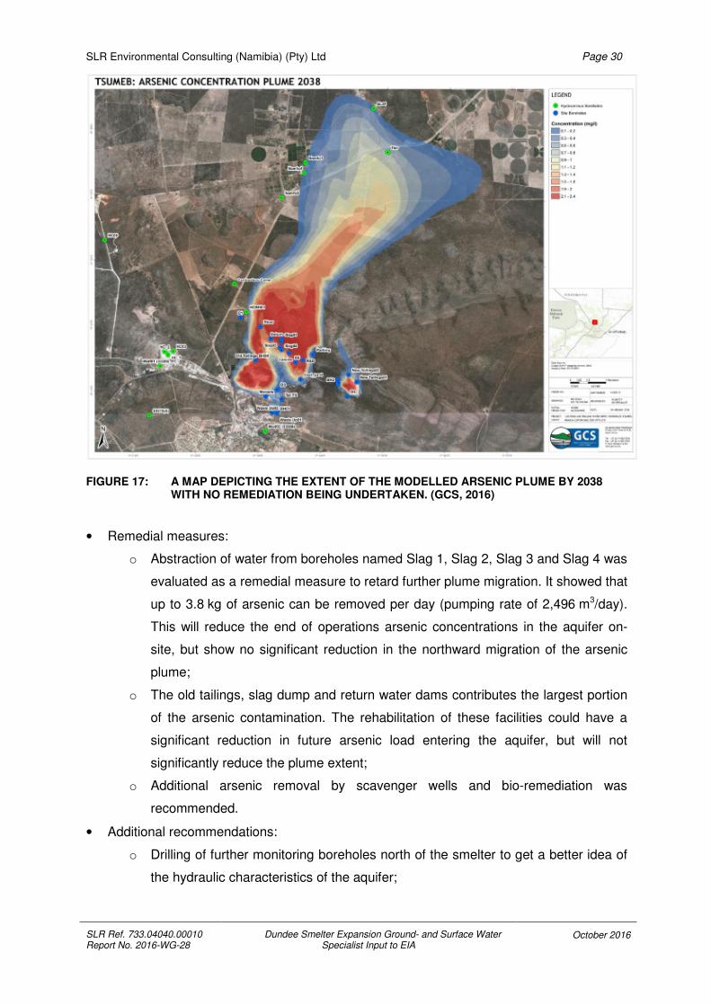
FIGURE 17: A MAP DEPICTING THE EXTENT OF THE MODELLED ARSENIC PLUME BY 2038 WITH NO REMEDIATION BEING UNDERTAKEN. (GCS, 2016)
• Remedial measures:
o Abstraction of water from boreholes named Slag 1, Slag 2, Slag 3 and Slag 4 was
evaluated as a remedial measure to retard further plume migration. It showed that
up to 3.8 kg of arsenic can be removed per day (pumping rate of 2,496 m3/day).
This will reduce the end of operations arsenic concentrations in the aquifer on-
site, but show no significant reduction in the northward migration of the arsenic
plume;
o The old tailings, slag dump and return water dams contributes the largest portion
of the arsenic contamination. The rehabilitation of these facilities could have a
significant reduction in future arsenic load entering the aquifer, but will not
significantly reduce the plume extent;
o Additional arsenic removal by scavenger wells and bio-remediation was
recommended.
• Additional recommendations:
o Drilling of further monitoring boreholes north of the smelter to get a better idea of
the hydraulic characteristics of the aquifer;

SLR Environmental Consulting (Namibia) (Pty) Ltd
SLR Ref. 733.04040.00010 Report No. 2016-WG-28
Dundee Smelter Expansion Ground- and Surface Water Specialist Input to EIA
October 2016
Page 31
o More frequent sampling of the private boreholes north of the site;
o Selenium concentrations to be included in reporting of future monitoring results;
o Redox potential for in-situ aquifer conditions should be evaluated;
o Vertical gradient information might be needed to further refine the transport
model, based on the existence of horizontal fractures, bedding planes and other
stratified geological flow impacts.
3.3.7 REVIEW OF GROUNDWATER MONITORING
SLR has received groundwater monitoring data for the smelter site in spreadsheets. The
data covers the period from February 2012 to July 2015. As highlighted in the previous
reports, some confusion still exists regarding the borehole numbers and the correct site co-
ordinates linked to each. The names used for the boreholes in historical reports are used for
the sake of continuity. Some constituents have also not been analysed for in all boreholes
and some obvious data anomalies exist in terms of reported values.
A number of progress reports have been written regarding the status of sampling and
monitoring on site. The latest available to SLR was dated 10 February 2016 and relates to
the sampling frequency and constituents to be analysed for (GCS, 2016). Based on the
advice received in these progress reports, the Client has changed the sampling methods,
making it difficult to compare the historic data to the latest data. The following has been
recommended in the latest progress report:
• Due to the inconsistency of the data it was recommended that current sampling methods
be used for another twelve months of monthly sampling to build a baseline data base,
which will then inform the decision on sampling frequency in future;
• A minimum list of constituents to be analysed for was suggested as follows:
o pH at 25oC o Barium
o Electrical Conductivity at 25oC o Cadmium
o TDS at 180oC o Chromium
o Total alkalinity o Cobalt
o Calcium o Copper
o Magnesium o Iron
o Sodium o Lead
o Potassium o Manganese
o Chloride o Molybdenum
o Sulphate o Vanadium
o Nitrate as N o Zinc

SLR Environmental Consulting (Namibia) (Pty) Ltd
SLR Ref. 733.04040.00010 Report No. 2016-WG-28
Dundee Smelter Expansion Ground- and Surface Water Specialist Input to EIA
October 2016
Page 32
o Aluminium o Selenium
o Arsenic
• The sulphate analyses results looks suspect and an alternative laboratory had been
suggested to do future analyses;
• Borehole “Waste Up 1” needs to be re-drilled due to a collapse in the original borehole.
DPMT has also produced a report on water quality at the Ondundu Community south east of
the smelter in June 2016, in which analyses of the drinking water originating from local
boreholes were discussed. Samples were taken from taps at three locations in Ondundu and
were analysed. All the samples were within the Group B drinking water quality for Namibia,
and this quality was only due to high levels of hardness detected. The arsenic content was
well below any of the Namibian Guideline values for drinking water (Dundee Precious Metals
Tsumeb, 2016).
3.4 GROUNDWATER QUALITY
It is important to view the groundwater quality monitoring results against some background
values for the larger karst region, specifically when looking at arsenic pollution. Data from
wider area studies does indicate elevated arsenic concentrations in areas not previously
affected by mining. Figure 18 from the Tsumeb Groundwater Study (GKW Consult / BICON
2003) indicates an arsenic concentration of 0.11 mg/l at borehole WW38837, much further to
the north east than any of those sampled in current studies commissioned by the smelter.
Concentrations of 0.05, 0.07 and 0.05 mg/l were measured at boreholes WW38445,
WW37893 and WW37894 respectively.
For the last round of groundwater sampling (July 2015) by DPMT at the various boreholes on
site the old sampling method was still used. Figure 19 indicates the location of the boreholes
on a map and Table 3 lists the co-ordinates where the boreholes are located. Table 4
indicates the water quality data that was available from this July 2015 sampling.

SLR Environmental Consulting (Namibia) (Pty) Ltd
SLR Ref. 733.04040.00010 Report No. 2016-WG-28
Dundee Smelter Expansion Ground- and Surface Water Specialist Input to EIA October 2016
Page 33
FIGURE 18: MAP INDICATING ARSENIC CONCENTRATIONS IN GROUNDWATER IN THE WIDER TSUMEB AREA (GKW CONSULT / BICON 2003)

SLR Environmental Consulting (Namibia) (Pty) Ltd
SLR Ref. 733.04040.00010 Report No. 2016-WG-28
Dundee Smelter Expansion Ground- and Surface Water Specialist Input to EIA
October 2016
Page 34
TABLE 3: LOCATION OF GROUNDWATER SAMPLING POINTS
Names Longitude Latitude
New Tailings 1 17.74281 -19.2301
Return 17.71967 -19.2195
Waste Up 2 17.72025 -19.2382
Calcine 17.72453 -19.2231
Parking 17.73101 -19.2233
River 17.71684 -19.2165
New Tailings 2 17.74063 -19.2283
Borehole 5 17.7264 -19.2254
Waste Up 1 17.72157 -19.2384
Waste Down (Tar Pit) 17.72287 -19.2348
Maroela 17.71848 -19.2341
Old Tailings 17.71565 -19.2250
FIGURE 19: MAP INDICATING THE LOCATION OF THE MONITORING BOREHOLES ON THE SMELTER SITE.
Arsenic content has been highlighted as the main signature constituent for indicating
pollution by the smelter and is also of most concern to the neighbouring groundwater users.
The figures below thus focus on the arsenic content measured in the boreholes with Figure
20 showing graduated circles of arsenic concentration for each of the boreholes for the July

SLR Environmental Consulting (Namibia) (Pty) Ltd
SLR Ref. 733.04040.00010 Report No. 2016-WG-28
Dundee Smelter Expansion Ground- and Surface Water Specialist Input to EIA
October 2016
Page 35
2015 sampling. From this figure one can see that only the Calcine- and Return Boreholes are
currently having arsenic concentrations exceeding the Namibian Guideline values for
drinking water. All other boreholes have concentrations falling within the Group B or better
quality for drinking water according to the Namibian Guideline. Figure 21 shows a time series
graph of the arsenic concentrations since February 2012. From the graph, it is clear that the
Calcine, Maroela and Return boreholes (right-hand axis of graph) have been impacted the
most by the smelter, with arsenic concentrations up to 10 mg/l in the Calcine borehole and
as high as 28 mg/l measured in the Return borehole for March 2014.
FIGURE 20: A MAP INDICATING THE ARSENIC CONCENTRATIONS IN THE MONITORING BOREHOLES ON SITE FOR JULY 2015.

SLR Environmental Consulting (Namibia) (Pty) Ltd
SLR Ref. 733.04040.00010 Report No. 2016-WG-28
Dundee Smelter Expansion Ground- and Surface Water Specialist Input to EIA October 2016
Page 36
TABLE 4: ANALYSES RESULTS FOR THE SAMPLES TAKEN IN JULY 2015 FROM BOREHOLES ON THE SMELTER SITE.
Constituents Unit
Namibian Drinking Water Guidelines
WHO Drinking
Water (2012)
New Tailings (BH2)
Borehole #5
(BH4)
Calcines
(BH13)
Maroela
(BH7)
Tar Pit / Waste Down (BH6)
Waste Up One
(BH5)
Old Tailings (BH9)
Return Water (BH10)
Waste Up Two
(BH11)
River (BH18)
Group A
Group B
Group C
Group D
Mixed sample
Mixed sample
Mixed sample
Mixed sample
Mixed sample
Mixed sample
Mixed sample
Mixed sample
Mixed sample
Mixed sample
pH–Value at 25°C - 6-9 5.5-9.5
4-11 4-11 NS 7.1 7.2 7.1 7.4 7.3 7.3 7.3 7.3 7.5 7.4
Electrical Conductivity
mS/m
150 300 400 400 NS 175 92 249 153 134 120 158 194 91 110
Total Dissolved Solids. at 180°C
mg/l NS NS NS NS NS 1300 660 1900 1100 890 720 1000 1300 510 640
Calcium as Ca mg/l 150 200 400 400 NS 178 115 237 180 141 135 159 162 99 124
Sodium as Na mg/l 100 400 800 800 NS 98 15 205 77 46 42 99 151 12 36
Potassium as K mg/l 200 400 800 800 NS 12 2.6 16 7 4.3 4.9 5.8 15 2.3 4.2
Total Alkalinity as CaCO3
mg/l NS NS NS NS NS 355 463 315 375 385 380 433 388 360 420
Chloride as Cl mg/l 250 600 1200 1200 NS 23 9.7 131 60 31 42 70 124 15 33
Sulphate as SO4 mg/l 200 600 1200 1200 NS 531 43 900 410 267 151 309 484 58 93
Nitrate as N mg/l 10 20 40 40 NS 1.7 0.67 1.3 0.6 0.89 4.8 4.7 0.54 0.15 2.5
Fluoride as F mg/l 1.5 2 3 3 1.5 <0.05 0.12 <0.05 0.11 <0.05 <0.05 <0.05 <0.05 1.2 <0.05
Nitrate as NO3 mg/l NS NS NS NS 50 7.5 3 5.6 2.6 3.9 21 21 2.4 0.7 11
Mercury as Hg µg/l 5 10 20 20 6 0.006 <0.001 0.24 0.032 0.029 0.005 0.066 0.047 0.001 0.004
Lead as Pb mg/l 0.05 0.1 0.2 0.2 0.01 0.28 0.003 0.001 0.001 0.014 0.001 0.047 0.001 <0.0005 0.003
Manganese as Mn
mg/l 0.05 1 2 2 0.4 0.25 <0.002 <0.002 0.012 1.7 <0.002 0.002 0.87 <0.002 0.008
Arsenic as As mg/l 0.1 0.3 0.6 0.6 0.01 0.014 0.008 28 0.057 0.014 0.005 0.006 3.1 0.009 0.005
Cadmium as Cd mg/l 0.01 0.02 0.04 0.04 0.003 0.001 <0.0001 0.004 <0.0001 <0.0001 <0.0001 0.002 <0.0001 <0.0001 <0.0001
Cobalt as Co mg/l 0.25 0.5 1 1 NS 0.029 <0.0004 0.001 0.002 0.054 <0.0004 0.001 0.015 0.001 <0.0004
Copper as Cu mg/l 0.5 1 2 2 2 3.8 0.004 0.008 0.009 0.014 0.006 0.046 0.008 0.005 0.01
Iron as Fe mg/l 0.1 1 2 2 NS 15 0.51 1 0.79 0.94 0.64 0.75 0.78 0.46 0.56
Zinc as Zn mg/l 1 5 10 10 NS 0.43 0.12 <0.05 <0.05 <0.05 <0.05 0.07 <0.05 <0.05 <0.05
Molybdenum mg/l 0.021 0.003 2.7 0.009 0.022 0.001 0.002 0.12 0.01 0.005

SLR Environmental Consulting (Namibia) (Pty) Ltd
SLR Ref. 733.04040.00010 Report No. 2016-WG-28
Dundee Smelter Expansion Ground- and Surface Water Specialist Input to EIA October 2016
Page 37
(The right hand axis of this graph indicates values for the Return, Maroela and Calcine boreholes).
FIGURE 21: A TIME SERIES GRAPH INDICATING THE ARSENIC CONCENTRATION MEASURED IN THE SITE BOREHOLES SINCE FEBRUARY 2012

SLR Environmental Consulting (Namibia) (Pty) Ltd
SLR Ref. 733.04040.00010 Report No. 2016-WG-28
Dundee Smelter Expansion Ground- and Surface Water Specialist Input to EIA
October 2016
Page 38
3.5 CONCLUSIONS AND RECOMMENDATIONS
The conclusion from the investigation of the groundwater work which has been undertaken in
the last few years at the DPMT site, is that there is a large amount of published material
relating to various studies, including modelling, a reasonable amount of water quality data
and a number of plans for groundwater monitoring and new boreholes. However, most of the
action on the ground has been focused on improving the monitoring network within the
smelter site, where significant pollution has already occurred, to monitor this; checking for
any increasing or decreasing trends. It is clear that the waste storage facilities (calcines,
slag, tailings and return water dams) are major sources of pollution. Monitoring results and
groundwater modelling indicates that this pollution is moving off-site, to the north of the
smelter and will continue to do so unless remedial action is taken.
See Table 5 for a summary of recommendations and the execution of these since 2009.

SLR Environmental Consulting (Namibia) (Pty) Ltd
SLR Ref. 733.04040.00010 Report No. 2016-WG-28
Dundee Smelter Expansion Ground- and Surface Water Specialist Input to EIA October 2016
Page 39
TABLE 5: LIST OF RECOMMENDATIONS MADE IN VARIOUS GROUNDWATER REPORTS FOR DPMT SINCE 2009
Report Recommendation Action taken
Preliminary Assessment of the
Contamination Risks to the Groundwater
Regime at the Tsumeb Smelter, Report 2,
December 2009
Use reverberatory slag as a leachate collection layer for the hazardous waste disposal site.
Unsure.
Do accelerated weathering tests on the reverberatory slag, should it be used as a leachate interception layer in the hazardous waste disposal facility.
Unsure.
Drilling of monitoring boreholes to the north of the new tailings dam.
Done. Additional boreholes planned for 2017. Most critical ones still to be identified.
Detailed geo-hydrological study should be done if the tailings dam is ever to be recommissioned.
N/a
Drilling monitoring boreholes downgradient of the old tailings facility.
Additional boreholes planned for 2017. Most critical ones still to be identified.
The arsenic calcine dumps should be covered by an engineered cover to reduce polluted seepage into the groundwater.
Terms of reference for a study into pollution control developed. ToR to be sent to market soon for tender purposes.
Drilling of monitoring boreholes downgradient of the arsenic calcine dumps.
Done. Additional boreholes planned for 2017. Most critical ones still to be identified.
Moving the converter dust to the hazardous waste disposal facility as soon as possible.
In progress – done as per plan.
Drilling of more monitoring boreholes to the north of the converter dust storage area.
Additional boreholes planned for 2017. Most critical ones still to be identified.
Drilling three monitoring boreholes at the hazardous waste disposal facility.
Additional boreholes planned for 2017. Most critical ones still to be identified.

SLR Environmental Consulting (Namibia) (Pty) Ltd
SLR Ref. 733.04040.00010 Report No. 2016-WG-28
Dundee Smelter Expansion Ground- and Surface Water Specialist Input to EIA October 2016
Page 40
Report Recommendation Action taken
Drilling of a monitoring borehole to the north of the tar pits.
Additional boreholes planned for 2017. Most critical ones still to be identified.
NCS groundwater data review and
monitoring, version final, May 2013
A new groundwater sampling method to be implemented
Done.
Correct the borehole numbering on data and fix borehole numbers to the borehole collars to ensure correct numbering of samples
Done. In progress – all boreholes to be fitted with new signs indicating new numbers and coordinates.
Recording of water levels in boreholes before purging or pumping
Done.
Discreet interval sampling needs to be done on all open boreholes
Being done.
Pump installation depths should be aligned with main flow zones in boreholes
Done. Pumps have been removed – new sampling method introduced.
Borehole samples should be taken as two samples for each borehole; one treated for metals analyses and one for major ion analyses
Done. This might change in future, depending on sampling programme.
Groundwater model should be updated every two years.
Done.
NCS groundwater flow and transport model,
version 1, July 2013
Groundwater levels needs to be monitored and a time series data set compiled.
In progress – part of monitoring programme.
Information on the vertical gradients existing in the aquifers needs to be generated.
In progress – specific depth sampling and groundwater characterisation forms part of the monitoring programme.
Tsumeb Water Supply and Smelter Studies A water balance needs to be developed for the smelter and its interaction with the
In Progress.

SLR Environmental Consulting (Namibia) (Pty) Ltd
SLR Ref. 733.04040.00010 Report No. 2016-WG-28
Dundee Smelter Expansion Ground- and Surface Water Specialist Input to EIA October 2016
Page 41
Report Recommendation Action taken
Phase 4: smelter sinkhole risk and
contaminant plume mapping, draft report 1,
version 1, December 2014
aquifer.
Drilling and geological mapping to be done to confirm the lineament positions, depth of weathering and geometry of Karst cavities.
To be further investigated in future.
Prevention of localised groundwater ingress near built structures.
Part of the surface water infrastructure upgrade plan for next few years. Initial work to commence in Q4 2016 / Q1 2017.
Detailed monitoring of groundwater quality and levels.
Done.
Lining of the return water dam with an impermeable liner.
Part of the surface water infrastructure upgrade plan for next few years.
Detailed hydrocensus to be undertaken on all boreholes, including those on surrounding farms.
Done.
Drilling of extra monitoring boreholes about 500 m to 1,000 m to the north of the site boundary.
Additional boreholes planned for 2017. Most critical ones still to be identified.
Aquifer test to be undertaken on boreholes to the north of the site.
To be further investigated in the near future.
Borehole water level time series data to be collected.
Done.
Additional characterisation of the aquifer to identify and quantify the existence of vertical heads and different flow zones.
In progress – specific depth sampling and groundwater characterisation forms part of the monitoring programme.
Fluid electrical conductivity logging of boreholes should be done to identify flow zones and understand the vertical properties
Done.

SLR Environmental Consulting (Namibia) (Pty) Ltd
SLR Ref. 733.04040.00010 Report No. 2016-WG-28
Dundee Smelter Expansion Ground- and Surface Water Specialist Input to EIA October 2016
Page 42
Report Recommendation Action taken
of the aquifer.
Geochemical characterisation of the slag piles, calcine heaps, and tailings should be done to calculate contamination loads to the aquifer.
Done.
Drilling boreholes into geophysical anomalies and pump testing of these.
To be further investigated in the near future.
Tsumeb Smelter Groundwater Model
Update, Report 1, 04 March 2016
Selenium and molybdenum to form part of constituents being analysed for in future water samples from off-site boreholes.
To be included in future monitoring programmes.
Further leach tests to be done in leach columns to determine the saturation point for the level of contamination that would lead to saturation of the adsorption/precipitation matrix.
To be further investigated in the near future.
Drilling of monitoring boreholes to the north of the site.
Additional boreholes planned for 2017. Most critical ones still to be identified.
More frequent sampling of boreholes on privately owned farms.
In progress – to be included in the 2017 monitoring programme.
Redox potential for in situ aquifer conditions should be evaluated.
In progress – specific depth sampling and groundwater characterisation forms part of the monitoring programme.
Generate vertical gradient information for the aquifer.
In progress – specific depth sampling and groundwater characterisation forms part of the monitoring programme.
Implement bioremediation measures for arsenic removal.
Terms of reference for a study into bioremediation has been developed. ToR to

SLR Environmental Consulting (Namibia) (Pty) Ltd
SLR Ref. 733.04040.00010 Report No. 2016-WG-28
Dundee Smelter Expansion Ground- and Surface Water Specialist Input to EIA October 2016
Page 43
Report Recommendation Action taken
be sent to market soon for tender purposes.
Pump boreholes Slag1 to Slag 4 as well as scavenger wells to retard the arsenic plume migration.
Terms of reference for a study into finding a method for arsenic plume migration retardation has been developed. ToR to be sent to market soon for tender purposes.
Memo: Sampling Frequency and
Constituents analysed, February 2016
Use current sampling methods monthly for twelve months to build baseline data and then re-evaluate future sampling programmes.
Done.
Samples should be analysed for the constituents listed in Section 3.3.6.
Being done.
An alternative laboratory should be used in future due to suspect analyses results being received from the current laboratory.
In progress – proposals received, and being evaluated.
Borehole “Waste Up 1” needs to be re-drilled.
Additional boreholes planned for 2017. Most critical ones to be identified – may or may not include “Waste Up 1”.

SLR Environmental Consulting (Namibia) (Pty) Ltd
SLR Ref. 733.04040.00010 Report No. 2016-WG-28
Dundee Smelter Expansion Ground- and Surface Water Specialist Input to EIA
October 2016
Page 44
The following is recommended to be part of the EMP:
• Additional boreholes should be drilled to the north of the site to better detect the arsenic
pollution plume migrationError! Reference source not found.;
• Gather all data available from DMPT, GROWAS and SLR databases for the area;
• The currently predicted movement of the arsenic plume needs to be re-evaluated, taking
into consideration the groundwater quality data from the TGWS.
• Rest water level data should be collected by monitoring 3 times a year in all boreholes;
• Sampling of boreholes used for irrigation and water supply;
• Determine vertical and horizontal gradients in the aquifer system;
• Implementation of the planned project for identifying major sources of groundwater
pollution and implementing the clean-up and remediation of these sources over the
DPMT site, for which a draft scope of work is already in place;
• Compile all data / results from above into a comprehensive new groundwater model
based on the existing regional model done 2003;
• Develop and update a dynamic water balance model to integrate into the future
groundwater model updates.
4 DUNDEE SMELTER EXPANSION SURFACE WATER STUDY
4.1 SCOPE OF WORK
The initial proposal included making recommendations for flood protection measures, with
the inclusion of peak flow and flood line calculations using a hydraulic flood modelling
package. Additionally a study to investigate and delineate clean (non-contact) and dirty
(contact) water catchments would have been undertaken as part of the storm water
management plan. However, once it was discovered that DPMT intends to use the Aurecon
reports which cover storm water assessment and storm water management, these aspects
of the proposal became redundant and a revised surface water Terms of Reference was
submitted to the Client.
The Aurecon report complies with EBRD PR4 Health and Safety, Section 31 (Natural
hazards), which stipulates “The client will identify and assess the potential impacts and risks
caused by natural hazards, such as earthquakes, landslides or floods as these relate to the
project.”

SLR Environmental Consulting (Namibia) (Pty) Ltd
SLR Ref. 733.04040.00010 Report No. 2016-WG-28
Dundee Smelter Expansion Ground- and Surface Water Specialist Input to EIA
October 2016
Page 45
4.2 REGIONAL HYDROLOGY
The study area is located on the eastern side of the Etosha Basin catchment, which is an
inland drainage system where runoff flows into the Etosha Pan where it then evaporates.
The area around Tsumeb is predominantly karstic, which means that it is formed from the
dissolution of soluble base rock (mainly dolomite and limestone in this area) which is
characterised by underground drainage systems with sink holes and caves. Due to the
geology of the area, there is no well-defined drainage pattern in the Tsumeb-Grootfontein
area, but rather many small individual drainage systems, dependant on the local geology.
FIGURE 22: SMELTER SITE SHOWING LOCAL HYDROLOGY
4.3 LOCAL HYDROLOGY
SRTM (Shuttle Radar Topography Mission) data from NASA was used to compile a ground
elevation map for the study area in conjunction with the local 1:250 000 topographical map
(Map 1916 Tsumeb). From this elevation data combined with satellite images, the local
catchment was identified which flows in a north westerly direction as shown in Figure 22. The
catchment was divided up into an upper section (which included the old eastern Tailings
Storage Facility (TSF) dam) covering an area of approximately 2.85 km2 and the lower
catchment below the TSF dam, which includes the main smelter and current western TSF

SLR Environmental Consulting (Namibia) (Pty) Ltd
SLR Ref. 733.04040.00010 Report No. 2016-WG-28
Dundee Smelter Expansion Ground- and Surface Water Specialist Input to EIA
October 2016
Page 46
areas, covering an area of 6.88 km2, giving a total catchment area at the outlet on the border
of the site boundary of 9.73 km2. To the west of the site is a drainage line (locally known as
the Jordan River), which has its catchment area in the townlands of Tsumeb, flowing in a
northerly direction along the western boundary of the site and then continuing off to the north
where it reportedly disappears into the ground. The Jordan River is not a natural water
course, relying on runoff from the central business area and the north eastern part of
Tsumeb, but typically has only a low flow or is temporarily dry if there is no rainfall. There is
some indication that a portion of the water pumped from Shaft 1 reaches the Jordan River,
but this is not confirmed.
Within the lower catchment area are two small dams (Dam 10 [also called No. 10 Gate Dam]
which contains decant water from the tailings dam plus return process water and Railway
Dam which contains overflow from Dam 10), see Figure 23.
It should be noted that there is a southern portion of the site which is not included in the main
catchment, being south of the catchment divide (as shown in Figure 22), which drains in a
south westerly direction into the Jordan River. Although the smelter expansion is in the main
catchment, there is some remnant industrial infrastructure located in this portion
(concentrator, lead furnace area, open pits) which may require remediation before site
closure, to ensure that no groundwater or surface water contamination can take place from
these areas towards the main residential and commercial area of Tsumeb.
4.4 PEAK FLOW ESTIMATION FOR LOCAL RUNOFF
No peak flows have been calculated for local runoff, as this information has already been
generated in the Aurecon reports of 2013 (Storm Water Assessment Study and Storm Water
Management Report).
4.5 SURFACE WATER QUALITY
No historical surface water sample programme has been undertaken at site, but a monitoring
programme is currently being set up which should start to provide baseline data for the site.
It is recommended that additional water samples should be collected from the drainage lines
that run through the main site (if not part of the routine sampling schedule) after any
significant rainfall event, to collect additional data for the site surface water quality, to provide
information on the quality of storm runoff water at the site which would be collected in the
planned pollution control dams (PCD’s).
Surface water samples were collected in October 2015 by Groundwater Consulting Services
at four locations within the site and one just outside the site at the Jordan River road crossing

SLR Environmental Consulting (Namibia) (Pty) Ltd
SLR Ref. 733.04040.00010 Report No. 2016-WG-28
Dundee Smelter Expansion Ground- and Surface Water Specialist Input to EIA
October 2016
Page 47
(see Figure 23). Samples within the site were collected at the Railway Dam and Dam 10
(both open water surfaces) as well as from Large Reservoir and Small Reservoir (concrete
elevated reservoirs) located on the southern watershed. The water which supplies the Large
Reservoir is municipal water pumped from municipal boreholes to the south of Tsumeb,
while the water supply to the Small Reservoir is raw water pumped from Shaft 1. Technically
the samples from the Large and Small Reservoirs are classified as groundwater, having
been pumped from boreholes. An analysis of the results from this sampling can be found in
Appendix 3.
FIGURE 23: LOCAL SURFACE WATER SAMPLING LOCATIONS
It can be seen from Figure 24 that the arsenic levels in all the surface water samples except
for the Municipal BH water are above acceptable guideline levels for human consumption,
but even the water quality from the Municipal boreholes is only Groups C (low health risk).

SLR Environmental Consulting (Namibia) (Pty) Ltd
SLR Ref. 733.04040.00010 Report No. 2016-WG-28
Dundee Smelter Expansion Ground- and Surface Water Specialist Input to EIA
October 2016
Page 48
FIGURE 24: ARSENIC RESULTS FROM SURFACE WATER SAMPLING OCTOBER 2015
In June 2016 DPMT collected five water samples from the Jordan River, starting upstream of
the smelter site (towards the town) and sampling at points along the boundary of DPMT with
the final sample being taken downstream of the smelter site (see Figure 25). Some of these
sites are similar to the surface water monitoring sites recommended in the 2013 Golder EMP
document.
An analysis of the results from this sampling indicates that it is likely that there are a number
of inflow points along the Jordan River, as the water quality changes quite considerably
between the sampling sites, (see Appendix 4). The most significant changes occur between
sampling point SW1 and SW2, with strong increases in many of the measured parameters.
There appears to be another inflow after SW2, as many parameters at SW3 have decreased
from the elevated levels at SW2. It should be noted that sampling sites SW 1 and SW2 are
upstream of the main part of the DPMT site, but are close to the historic Tsumeb Mine area.
After SW3 many parameter levels stabilise somewhat, or increase slightly. This analysis is
carried out on a single set of results (excluding the additional SW4 2015 sample), so further
data should be collected before undertaking a more detailed analysis of this surface water
system. It should also be noted that Tsumeb Municipality discharges some effluent from the
local sewage plant (after the maturation ponds) into the environment, so this will probably be
an additional input to the Jordan River somewhere around site SW4, but this should be
confirmed by a site investigation. Water samples are collected from this discharge by the
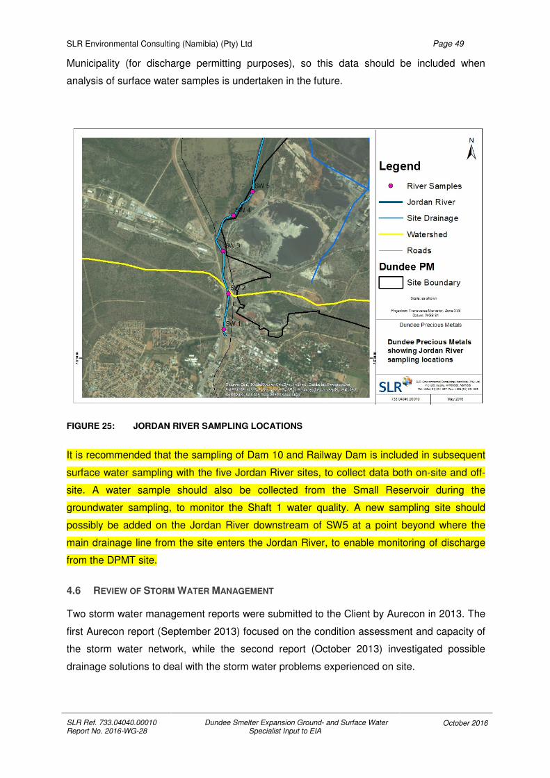
SLR Environmental Consulting (Namibia) (Pty) Ltd
SLR Ref. 733.04040.00010 Report No. 2016-WG-28
Dundee Smelter Expansion Ground- and Surface Water Specialist Input to EIA
October 2016
Page 49
Municipality (for discharge permitting purposes), so this data should be included when
analysis of surface water samples is undertaken in the future.
FIGURE 25: JORDAN RIVER SAMPLING LOCATIONS
It is recommended that the sampling of Dam 10 and Railway Dam is included in subsequent
surface water sampling with the five Jordan River sites, to collect data both on-site and off-
site. A water sample should also be collected from the Small Reservoir during the
groundwater sampling, to monitor the Shaft 1 water quality. A new sampling site should
possibly be added on the Jordan River downstream of SW5 at a point beyond where the
main drainage line from the site enters the Jordan River, to enable monitoring of discharge
from the DPMT site.
4.6 REVIEW OF STORM WATER MANAGEMENT
Two storm water management reports were submitted to the Client by Aurecon in 2013. The
first Aurecon report (September 2013) focused on the condition assessment and capacity of
the storm water network, while the second report (October 2013) investigated possible
drainage solutions to deal with the storm water problems experienced on site.

SLR Environmental Consulting (Namibia) (Pty) Ltd
SLR Ref. 733.04040.00010 Report No. 2016-WG-28
Dundee Smelter Expansion Ground- and Surface Water Specialist Input to EIA
October 2016
Page 50
It is understood that the Client plans to start to implement parts of this storm water plan in a
phased approach over the next few years (see Table 6). The Aurecon storm water plan
upgrades the existing storm water drainage to a gravity system and includes a re-design of
the on-site open and concrete lined channels, realignment of concrete hard stands and the
construction of silt traps and pollution control dams (PCD’s) for the containment of polluted
runoff. It divides the catchment area into the “upper” eastern non-contact (clean) water
runoff, which would use a diversion berm to route the water to the north around the main
smelter area (Figure 26), (significantly reducing the flooding within the plant), and the “lower”
contact (dirty) water runoff from the main smelter site and associated catchment, which will
be collected by the gravity flow system (Figure 27) and drain in a north westerly direction into
a number of PCD’s (maximum of three with the actual number to depend on available space
within the plant area, but one large single PCD is the best option if available space can be
found). It is understood that the clean water diversion berm may not be implemented as the
cost is too high (Table 6, No. 4). This then means that the entire contact water system will
need to be re-designed to account for the additional storm water runoff which will flow onto
the site from the upper catchment area. It is also understood that the Client has decided to
construct two PCD’s adjacent to each other (to spread the capital expenditure), as well as to
line Dam 10 after the first PCD is commissioned.
It should be noted that the upper catchment being categorised as non-contact assumes
rehabilitation of the old eastern TSF in this catchment as well as the historical slag area.
Rehabilitation of the old eastern TSF in the upper catchment should include a dam basin
survey to calculate the storage capacity of the old eastern TSF, as well as catchment
calculations to provide estimated return interval storm volumes likely to be captured in the
dam. In small return period storms the dam should have capacity to collect all runoff
produced from the catchment and then contain this water allowing evaporation and infiltration
to deplete the stored water. The relevant South African regulations (Regulation No. GN 704
of the National Water Act (1998)) for pollution control dams (PCD) stipulate that a PCD must
only spill on average once in 50 years, which would be a desired design criteria for this site
(as Namibia does not have specific legislation in place regulating storm water management).
From the previously mentioned survey and calculations the dam volume and storm volumes
would show whether the old TSF would need to be modified to contain storm runoff, such
that it would only spill after the 1:50 year design storm.
Rehabilitation of the historical slag area should be undertaken on the eastern side along the
main drainage line running south, as well as the southern edge along the diversion channel,
to prevent contact water from the historical slag area flowing into the proposed non-contact
water system discussed below.
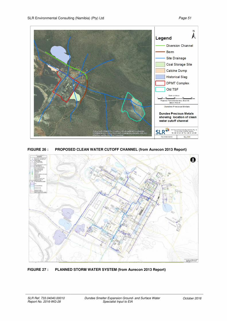
SLR Environmental Consulting (Namibia) (Pty) Ltd
SLR Ref. 733.04040.00010 Report No. 2016-WG-28
Dundee Smelter Expansion Ground- and Surface Water Specialist Input to EIA
October 2016
Page 51
FIGURE 26 : PROPOSED CLEAN WATER CUTOFF CHANNEL (from Aurecon 2013 Report)
FIGURE 27 : PLANNED STORM WATER SYSTEM (from Aurecon 2013 Report)

SLR Environmental Consulting (Namibia) (Pty) Ltd
SLR Ref. 733.04040.00010 Report No. 2016-WG-28
Dundee Smelter Expansion Ground- and Surface Water Specialist Input to EIA
October 2016
Page 52
FIGURE 28 : CURRENT STORMWATER LAYOUT (from Golder Associates ESIA Report 2013)
The current storm water drainage comprises two main drainage pipelines through the plant
area which end in sumps, from where the runoff is pumped to various points inside the plant
(see Figure 28). Problems have been experienced with silting of the storm water system and
some of the infrastructure is inadequate for the generated runoff, resulting in ponding of
runoff at a number of identified sites around the plant after storm events (see Figure 29).
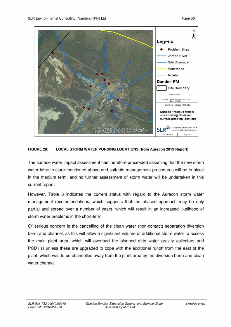
SLR Environmental Consulting (Namibia) (Pty) Ltd
SLR Ref. 733.04040.00010 Report No. 2016-WG-28
Dundee Smelter Expansion Ground- and Surface Water Specialist Input to EIA
October 2016
Page 53
FIGURE 29: LOCAL STORM WATER PONDING LOCATIONS (from Aurecon 2013 Report)
The surface water impact assessment has therefore proceeded assuming that the new storm
water infrastructure mentioned above and suitable management procedures will be in place
in the medium term, and no further assessment of storm water will be undertaken in this
current report.
However, Table 6 indicates the current status with regard to the Aurecon storm water
management recommendations, which suggests that the phased approach may be only
partial and spread over a number of years, which will result in an increased likelihood of
storm water problems in the short-term
Of serious concern is the cancelling of the clean water (non-contact) separation diversion
berm and channel, as this will allow a significant volume of additional storm water to access
the main plant area, which will overload the planned dirty water gravity collectors and
PCD (‘s) unless these are upgraded to cope with the additional runoff from the east of the
plant, which was to be channelled away from the plant area by the diversion berm and clean
water channel.
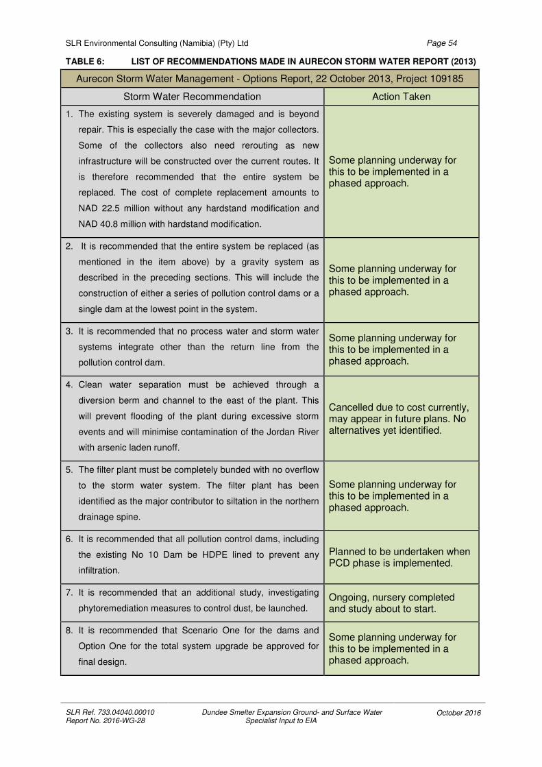
SLR Environmental Consulting (Namibia) (Pty) Ltd
SLR Ref. 733.04040.00010 Report No. 2016-WG-28
Dundee Smelter Expansion Ground- and Surface Water Specialist Input to EIA
October 2016
Page 54
TABLE 6: LIST OF RECOMMENDATIONS MADE IN AURECON STORM WATER REPORT (2013)
Aurecon Storm Water Management - Options Report, 22 October 2013, Project 109185
Storm Water Recommendation Action Taken
1. The existing system is severely damaged and is beyond
repair. This is especially the case with the major collectors.
Some of the collectors also need rerouting as new
infrastructure will be constructed over the current routes. It
is therefore recommended that the entire system be
replaced. The cost of complete replacement amounts to
NAD 22.5 million without any hardstand modification and
NAD 40.8 million with hardstand modification.
Some planning underway for this to be implemented in a phased approach.
2. It is recommended that the entire system be replaced (as
mentioned in the item above) by a gravity system as
described in the preceding sections. This will include the
construction of either a series of pollution control dams or a
single dam at the lowest point in the system.
Some planning underway for this to be implemented in a phased approach.
3. It is recommended that no process water and storm water
systems integrate other than the return line from the
pollution control dam.
Some planning underway for this to be implemented in a phased approach.
4. Clean water separation must be achieved through a
diversion berm and channel to the east of the plant. This
will prevent flooding of the plant during excessive storm
events and will minimise contamination of the Jordan River
with arsenic laden runoff.
Cancelled due to cost currently, may appear in future plans. No alternatives yet identified.
5. The filter plant must be completely bunded with no overflow
to the storm water system. The filter plant has been
identified as the major contributor to siltation in the northern
drainage spine.
Some planning underway for this to be implemented in a phased approach.
6. It is recommended that all pollution control dams, including
the existing No 10 Dam be HDPE lined to prevent any
infiltration.
Planned to be undertaken when PCD phase is implemented.
7. It is recommended that an additional study, investigating
phytoremediation measures to control dust, be launched. Ongoing, nursery completed and study about to start.
8. It is recommended that Scenario One for the dams and
Option One for the total system upgrade be approved for
final design.
Some planning underway for this to be implemented in a phased approach.

SLR Environmental Consulting (Namibia) (Pty) Ltd
SLR Ref. 733.04040.00010 Report No. 2016-WG-28
Dundee Smelter Expansion Ground- and Surface Water Specialist Input to EIA
October 2016
Page 55
4.7 REVIEW OF SITE WATER BALANCE STUDIES
4.7.1 GENERAL
A number of reports have been produced which include some sort of water balance as part
of the study or have values for water demand for certain infrastructure.
The Golder EIA Report (2013) quotes demand figures for raw water for process use of
225 m3/h for the Reverse Osmosis Plant, 8 m3/h for the Effluent Treatment Plant, 5 m3/h for
the CV Filter and 12 m3/h for the Gas Cleaning Process, plus cooling water demand for
convertor hoods and convertor blower of 795 m3/h (for a single convertor). The sulphuric acid
plant is quoted as requiring 60 m3/h of raw water and 12 m3/h of potable water.
The Worley Parsons Smelter Expansion PFS (2015) quotes the current raw water pumping
capacity as 300 m3/h (from Shaft 1), which would need to be upgraded to approximately
400 m3/h for the increased processing, but mentioned that the current raw water demand is
not clearly identified and further investigations should be carried out.
From discussions with the Client is appears that a dynamic water balance is being completed
by Golder, which should be finalised in the near future, so no detailed calculations for the
water balance situation will be made here.
The EBRD PR3 Section 18 notes that “For projects with a high water demand (greater than
5,000 m3/day), the following must be applied:
• a detailed water balance must be developed, maintained and reported annually to the
EBRD”.
It is unclear what the current daily water demand is running at, but the Golder dynamic water
balance will provide an initial means to comply with this EBRD requirement.
4.7.2 PROCESS WATER
Aurecon produced a number of reports in 2013 including “Process Water Options Analysis
Report” and “Process Water Assessment Study” which are the results of three weeks spent
on site checking the process water systems. The Analysis Report gives a breakdown of the
planned main process water streams on the site as follows;
• The slag mill will use raw water
• The furnace Evaporative Cooling Chambers (ECC) will use low-arsenic reclaim water
(from the filter plant)
• The oxygen plants will use a mixture of raw and domestic water
• The Water Treatment Works (WTW) will use a mixture of raw and domestic water

SLR Environmental Consulting (Namibia) (Pty) Ltd
SLR Ref. 733.04040.00010 Report No. 2016-WG-28
Dundee Smelter Expansion Ground- and Surface Water Specialist Input to EIA
October 2016
Page 56
• Reclaim water from blowdown and WTW wastes are routed to the filter plant reclaim
dam
• Filtrate from the filter plant is routed to the reclaim dam at the filter plant
• The Ausmelt and Sulphuric Acid Plant (SAP) cooling circuits will use Reverse
Osmosis (RO) water from the respective WTWs
• Converter furnace heat exchangers, and compressors at the power plant and the
Ausmelt cold-loop will use softened water from the existing WTW
• The SAP Effluent Treatment Plant (ETP) will make use of low-arsenic reclaim water
from the filter plant and produce an arsenic-rich effluent to be routed to the No. 10
dam.
• Granulation pits wouldl use high-arsenic reclaim water sourced from the No. 10 dam,
(but DPMT is currently using slow cooling instead of granulation).
• Storm water reports to the filter plant reclaim water dam and the slag mill.
The Assessment Study estimated that the average raw water demand for the site is 123 m3/h
(which will have increased significantly with the construction of the sulphuric acid plant and
will further increase with the planned smelter expansion), with an estimated 4 m3/h domestic
water also being used. The overall assessment for the water balance indicates that more
than 67 % of the water is lost to evaporation in the various processing units and from the
tailings dams, 31 % is lost to infiltration from dams and spraying and the remaining 2 % is
discharged from the site as wastewater effluent. (Currently only sewage water effluent is sent
to the reed beds, where it should be added to the evaporation and infiltration values in the
water balance, if these beds do not discharge off-site).
4.7.3 WATER BALANCE CONCLUSIONS
The various water supplies to the site originate mainly with groundwater abstraction
(supplying raw water from Shaft 1 and some additional water from recovery boreholes) and a
small domestic water supply from Tsumeb Municipality, plus occasional small additions from
storm water after rainfall events. A small proportion of the water supplied to site is then
discharged as wastewater effluent. The supplies to the site can then be further divided into
cooling (or softened) water, boiler feed (or RO) water and reclaim water streams indicating
that the water balance for the site is a complicated system with many interactions and
possible combinations for water consumption. The raw water supply to the site is
predominately used at the sulphuric acid plant, the oxygen plant and the water treatment
works (where it is treated to supply cooling and boiler feed water). The slag mill receives
water from the reclaim dam and No 10 dam. The current water use is being modified as
additional infrastructure is added, so it is recommended that the dynamic water balance

SLR Environmental Consulting (Namibia) (Pty) Ltd
SLR Ref. 733.04040.00010 Report No. 2016-WG-28
Dundee Smelter Expansion Ground- and Surface Water Specialist Input to EIA
October 2016
Page 57
being produced is regularly updated when changes to the plant and operations take place.
This dynamic water balance should also be revised if additional groundwater studies provide
additional data, as the currently used groundwater values will provide a significant input to
the balance. Changes to these inputs may significantly affect the balance streams and the
possibilities for the use of various water qualities for the different processes, such that the
most efficient re-use of site water may change with new data. Once a detailed water balance
has been completed, this will form the basis for future abstraction and discharge permit
applications.
4.8 ENVIRONMENTAL IMPACTS FOR SURFACE WATER
The main likely surface water environmental impacts at the DPMT site will be from pollution
generated from the runoff generated within the main site, or to a smaller extent from any
spillage from the old TSF dam (located upstream to the east of the main site), in the event of
a significant rainfall event, plus the wastewater effluent discharge. An additional smaller
surface water impact is generated from the wastewater effluent discharge continually sent to
the reed beds. However, for the purpose of this study, only additional polluted runoff
generated as a result of the smelter expansion will be investigated for the impact
assessment.
Figure 30 shows the main surface water related site infrastructure outside of the plant area,
which shows that there are a number of areas where the surface drainage is in contact with
sites of concern. The main areas where storm water could be a problem for the natural
surface drainage are the coal storage area, the eastern edge of the historical slag area and
the calcine dump. However, with the exception of the historical slag all the others are within
the main plant area and will be addressed by the storm water management plan (discussed
previously).

SLR Environmental Consulting (Namibia) (Pty) Ltd
SLR Ref. 733.04040.00010 Report No. 2016-WG-28
Dundee Smelter Expansion Ground- and Surface Water Specialist Input to EIA
October 2016
Page 58
FIGURE 30: LOCATION OF SITE WATER RELATED INFRASTRUCTURE
5 GROUND- AND SURFACE WATER IMPACT ASSESSMENT
Based on the review of available data, an assessment of the cumulative potential
environmental impacts that the expansion plans for the Dundee Smelter would have on
groundwater and surface water have been identified, building on previous impact
assessments for the site prior to the smelter expansion.
A review of previous impact assessments was made by searching through previous
Environmental Impact Assessment (EIA) and Scoping Reports, which were the following;
• 2011 Environmental Assessment for the Tsumeb Smelter by Synergistics
Environmental Services, (no impact assessment was included, but groundwater
protection was addressed with objectives for the new tailings dam to be rehabilitated,
an additional borehole to the north of the smelter operations and quarterly
groundwater monitoring with analysis by an independent laboratory in the EMP
section. No surface water objectives mentioned);
• 2013 ESIA for New Sulphuric Acid Plant, Tsumeb by Golder Associates, (see tables
below)

SLR Environmental Consulting (Namibia) (Pty) Ltd
SLR Ref. 733.04040.00010 Report No. 2016-WG-28
Dundee Smelter Expansion Ground- and Surface Water Specialist Input to EIA
October 2016
Page 59
TABLE 7: SUMMARY OF GROUNDWATER IMPACTS FROM GOLDER ESIA 2013
Groundwater Impacts
Phase Impact Consequence
Construction Phase
Hydrocarbon spills / waste generation Moderate
Sanitary waste discharge Low
Operations Phase
Spillage of contaminants Moderate
Process water management High
Sulphur dioxide emissions to atmosphere + High
Decommissioning Phase
Chemical spills during decommissioning Moderate
Temporary storage of contaminated soil / waste Moderate
TABLE 8: SUMMARY OF SURFACE WATER IMPACTS FROM GOLDER ESIA 2013
Surface Water Impacts
Phase Impact Consequence
Construction Phase
Increased soil erosion and runoff Moderate
Contamination from hydrocarbon spillage Moderate
Operations Phase
Leakage / spillage from sulphuric acid storage Moderate
Contamination from weak acid effluent generated Moderate
Decommissioning Phase
Contamination from solid waste generated from acid plant, while stored at hazardous waste facilities
Moderate
Additionally, Environmental Management Plans (EMP) and Scoping Reports for additional
work at the site were reviewed to gather a complete picture of previous assessments.
• 2014 Scoping Report for the 11kV Power Line for DPMT, by SLR, (no specific
groundwater or surface water impacts were identified outside of the generic waste
management and hydrocarbon spillages during the construction phase, which were
rated as medium significance for the unmitigated and low for the mitigated case);
• 2014 Scoping Report for the New Sewerage Plant, DPMT, by SLR, (the assessment
for possible ground and surface water contamination from spillage or release of
sewage was rated as medium without mitigation and low with mitigation measures);
• 2015 EMP for the DPMT Hazardous Waste Disposal Site, by SLR, (no impact
assessment was included, but protection of groundwater and surface water
environment was addressed with specific actions and schedules, including monitoring
and maintenance);

SLR Environmental Consulting (Namibia) (Pty) Ltd
SLR Ref. 733.04040.00010 Report No. 2016-WG-28
Dundee Smelter Expansion Ground- and Surface Water Specialist Input to EIA
October 2016
Page 60
In the current assessment the impact rating for each potential impact along with the criteria
used to rate each impact is clearly stated. The potential impacts are rated with the
assumption that no mitigation measures are applied and then again with mitigation.
The assessment criteria used for ranking these impacts is explained in Table 9 below.
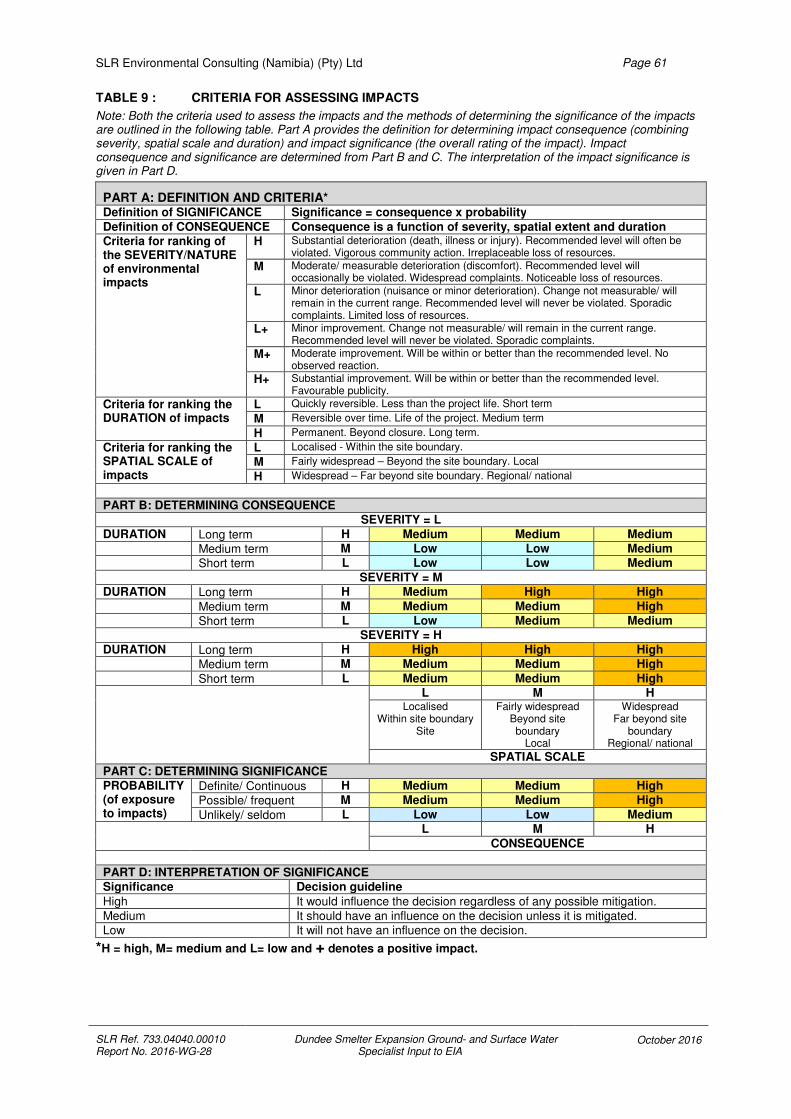
SLR Environmental Consulting (Namibia) (Pty) Ltd
SLR Ref. 733.04040.00010 Report No. 2016-WG-28
Dundee Smelter Expansion Ground- and Surface Water Specialist Input to EIA
October 2016
Page 61
TABLE 9 : CRITERIA FOR ASSESSING IMPACTS
Note: Both the criteria used to assess the impacts and the methods of determining the significance of the impacts are outlined in the following table. Part A provides the definition for determining impact consequence (combining severity, spatial scale and duration) and impact significance (the overall rating of the impact). Impact consequence and significance are determined from Part B and C. The interpretation of the impact significance is given in Part D.
PART A: DEFINITION AND CRITERIA* Definition of SIGNIFICANCE Significance = consequence x probability
Definition of CONSEQUENCE Consequence is a function of severity, spatial extent and duration Criteria for ranking of the SEVERITY/NATURE of environmental impacts
H Substantial deterioration (death, illness or injury). Recommended level will often be violated. Vigorous community action. Irreplaceable loss of resources.
M Moderate/ measurable deterioration (discomfort). Recommended level will occasionally be violated. Widespread complaints. Noticeable loss of resources.
L Minor deterioration (nuisance or minor deterioration). Change not measurable/ will remain in the current range. Recommended level will never be violated. Sporadic complaints. Limited loss of resources.
L+ Minor improvement. Change not measurable/ will remain in the current range. Recommended level will never be violated. Sporadic complaints.
M+ Moderate improvement. Will be within or better than the recommended level. No observed reaction.
H+ Substantial improvement. Will be within or better than the recommended level. Favourable publicity.
Criteria for ranking the DURATION of impacts
L Quickly reversible. Less than the project life. Short term
M Reversible over time. Life of the project. Medium term
H Permanent. Beyond closure. Long term.
Criteria for ranking the SPATIAL SCALE of impacts
L Localised - Within the site boundary.
M Fairly widespread – Beyond the site boundary. Local
H Widespread – Far beyond site boundary. Regional/ national
PART B: DETERMINING CONSEQUENCE SEVERITY = L
DURATION Long term H Medium Medium Medium Medium term M Low Low Medium Short term L Low Low Medium
SEVERITY = M DURATION Long term H Medium High High
Medium term M Medium Medium High Short term L Low Medium Medium
SEVERITY = H
DURATION Long term H High High High Medium term M Medium Medium High
Short term L Medium Medium High L M H
Localised Within site boundary
Site
Fairly widespread Beyond site boundary
Local
Widespread Far beyond site
boundary Regional/ national
SPATIAL SCALE
PART C: DETERMINING SIGNIFICANCE PROBABILITY (of exposure to impacts)
Definite/ Continuous H Medium Medium High
Possible/ frequent M Medium Medium High
Unlikely/ seldom L Low Low Medium
L M H
CONSEQUENCE
PART D: INTERPRETATION OF SIGNIFICANCE Significance Decision guideline
High It would influence the decision regardless of any possible mitigation.
Medium It should have an influence on the decision unless it is mitigated. Low It will not have an influence on the decision.
*H = high, M= medium and L= low and + denotes a positive impact.

SLR Environmental Consulting (Namibia) (Pty) Ltd
SLR Ref. 733.04040.00010 Report No. 2016-WG-28
Dundee Smelter Expansion Ground- and Surface Water Specialist Input to EIA
October 2016
Page 62
5.1 GROUNDWATER IMPACT ASSESSMENT
The groundwater impact assessment is summarised in Table 10 and in Table 11 below,
focusing on potential impacts on groundwater quantity and groundwater quality respectively.
In Table 10 an assessment of the impact of the Dundee smelter expansion on groundwater
quantity is undertaken and identifies a significant increase in groundwater use, which should
reflect in amplification of the cone of depression caused by pumping of groundwater. The
2013 groundwater study report indicates no cone of depression existing currently, based on
groundwater piezometric head as mapped at the time (GCS, 2013). The Phase Two report of
the same year concludes that no changes in groundwater levels are expected (GCS, 2013
(2)). This also means no positive impact is caused by anthropogenic heads created on the
tailings storage facility or any of the other dumps, leading to increased recharge. In the
absence of available water balance figures and abstraction rates, it is concluded that a
dynamic water balance model be developed and an upgraded groundwater model be
presented to indicate the expected cone of depression based on the current abstraction
rates, including the suggested abstraction from the Slag 1 – Slag 4 boreholes for remedial
action.
The unmitigated scenario is assessed as medium impact, but with the recommended
mitigation measures of the development of a functional water balance and improved
monitoring the assessment reduces to low.
In Table 11 the assessment of impacts of the Dundee smelter expansion on groundwater
quality is undertaken and shows that groundwater quality could deteriorate further. The
background existing before the proposed expansion indicates that the smelter site is already
impacting significantly on groundwater quality, both on and off-site, with elevated metals and
sulphate concentrations being the most prominent indicators of this. The expansion would
probably increase this impact, though not significantly higher than what is already in
existence. Plume modelling from the 2013 and 2016 groundwater reports indicate that
arsenic concentrations are elevated off-site and the plume will continue to move to the north,
eventually impacting on the irrigation boreholes (GCS, 2013 and GCS, 2016). The proposed
mitigation and remedial actions from these reports are not indicating any significant
improvement being recorded, therefore further investigation into remedial action is needed.
The unmitigated scenario is assessed as a high impact, therefore mitigation measures are
recommended to ensure that the impact is reduced.
With the proposed mitigation and remedial action being implemented the impact assessment
reduces to medium.

SLR Environmental Consulting (Namibia) (Pty) Ltd
SLR Ref. 733.04040.00010 Report No. 2016-WG-28
Dundee Smelter Expansion Ground- and Surface Water Specialist Input to EIA October 2016
Page 63
TABLE 10 : IMPACT OF PROPOSED DUNDEE SMELTER EXPANSION ON GROUNDWATER QUANTITY
Potential impact of the planned Dundee smelter expansion
on Groundwater Quantity
Unmitigated assessment Mitigated assessment
Severi
ty
Du
rati
on
Sp
ati
al S
cale
Co
nseq
uen
ce
Pro
bab
ilit
y
Sig
nif
ican
ce Mitigation measures
Severi
ty
Du
rati
on
Sp
ati
al S
cale
Co
nseq
uen
ce
Pro
bab
ilit
y
Sig
nif
ican
ce
RISK: Groundwater Levels
Severity:
Increased abstraction of groundwater for the expansion could cause a local cone of depression at the abstraction boreholes and the shaft. Indications are that no significant abstraction increase is planned and current abstraction is showing no measurable impact.
Duration:
The duration of potential for significant cones of depression forming would be for the life of the facility and causing a low impact.
Spatial scale:
Current maps indicates no spatial extent beyond the site boundary therefore a low influence in both the unmitigated and mitigated cases
Consequence:
Based on the above assessment the determining consequence is low in the unmitigated case.
Probability:
Probability of occurrence is medium in the unmitigated case. A radius of influence is likely but not detected due to lack of monitoring.
Significance:
Summarising the above assessment, the overall significance is rated as medium in the unmitigated case.
L L L L M M
Objective:
To reduce the impact of the cone of depression caused by groundwater abstraction
Actions:
Monitoring water levels in boreholes on site and off site (including Tsumeb Municipality and DWAF monitoring and production boreholes) to monitor possible cone of depression caused by pumping from Shaft 1. Feedback from monitoring to into the groundwater model updates.
Develop a dynamic water balance model for the site to inform future remedial action.
Obtain groundwater abstraction permit from Ministry of Agriculture, Water and Forestry.
Emergency situations:
None identified for the current expansion.
L L L L L L

SLR Environmental Consulting (Namibia) (Pty) Ltd
SLR Ref. 733.04040.00010 Report No. 2016-WG-28
Dundee Smelter Expansion Ground- and Surface Water Specialist Input to EIA October 2016
Page 64
TABLE 11 : IMPACT OF PROPOSED DUNDEE SMELTER EXPANSION ON GROUNDWATER QUALITY
Potential impact of the planned Dundee smelter expansion
on Groundwater Quality.
Unmitigated assessment Mitigated assessment
Severi
ty
Du
rati
on
Sp
ati
al S
cale
Co
nseq
uen
ce
Pro
bab
ilit
y
Sig
nif
ican
ce Mitigation measures
Maintain efficient and effective management procedures for operating smelter.
Severi
ty
Du
rati
on
Sp
ati
al S
cale
Co
nseq
uen
ce
Pro
bab
ilit
y
Sig
nif
ican
ce
RISK: Groundwater Pollution
Severity:
Contamination of groundwater as a result of the smelter activities will continue and is already occurring off-site. The severity is considered high in the unmitigated case and medium in the mitigated case, since the Group B water quality limit can be reached with mitigation.
Duration:
The duration of potential for pollution from polluted groundwater is for longer than the life of the project, so a high impact in the unmitigated state is assigned and medium for the mitigated state, since remedial action can reduce the period of impact.
Spatial scale:
Polluted groundwater was modelled to spread far beyond the site boundary as contamination transport is expected to follow the groundwater flow patterns, hence a high rating in both the unmitigated and mitigated cases
Consequence:
Based on the above assessment the determining consequence is high in the unmitigated case and medium in the mitigated case.
Probability:
Probability of occurrence is high in the unmitigated case and medium in the mitigated case.
Significance:
Summarising the above assessment, the overall significance is rated as high in the unmitigated case and medium in the mitigated case.
H H H H H H
Objective:
Reduce the off-site spread of contaminated groundwater.
Actions:
Complete the study on sources of contamination and potential remedial action (currently only in a planning stage with scope of work developed).
Development of an improved groundwater model.
Abstraction of contaminated groundwater to reduce plume movement to the north. This will need associated water treatment and disposal.
Rehabilitation of polluting dumps in line with the closure plan recommendations.
Dispose of waste materials properly at a suitable disposal site. This would mean establishment of new sites for the extra waste volumes being generated.
Implement the Phytoremediation trials in line with the closure plan.
Drilling of additional monitoring boreholes off-site in the downgradient direction and into different geological / hydrogeological environments.
Include regional groundwater monitoring from existing farm and municipal boreholes and produce a detailed groundwater monitoring schedule.
Regular sampling at monitoring boreholes to quickly identify change in groundwater quality.
Emergency situations:
None identified for the current expansion.
M M M M M M

SLR Environmental Consulting (Namibia) (Pty) Ltd
SLR Ref. 733.04040.00010 Report No. 2016-WG-28
Dundee Smelter Expansion Ground- and Surface Water Specialist Input to EIA
October 2016
Page 65
5.2 SURFACE WATER IMPACT ASSESSMENT
The surface water impact assessment has proceeded assuming that the new storm water
infrastructure and management procedures recommended by Aurecon in 2013 will be in
place in the medium term, as well as rehabilitation of the (eastern) old tailings dam and
historical slag areas, to ensure that runoff generated in this catchment remains non-contact.
To look at the impact of the smelter expansion, it is necessary to look at any previous
surface water impact assessments for the site prior to the expansion and see whether there
will be any additional impacts once the smelter expansion is completed. The earliest
environmental assessment (Synergistics 2013) did not contain any specific impact
assessment for surface water or any environmental management plan relating to surface
water. The ESIA undertaken by Golder Associates in September 2013 for the new sulphuric
acid plant concentrated on the additional infrastructure and the surface water impact
assessment for the construction and operational phases only addresses issues relating to
the new acid plant, while the decommissioning phase only identifies issues from acid plant
waste stored at the hazardous waste facilities. The Scoping Report for the Power Line (2014)
only identified Construction phase impacts, while the Scoping Report for the new Sewerage
Plant (2014) only identified contamination from spillage or release of sewage. The EMP for
the Hazardous Waste Disposal Site (2015) has no impact assessment, only objectives,
actions and schedules as part of the EMP. From this review it appears that there is no
overall site-wide surface water impact assessment, from which to add any additional impacts
that the smelter expansion may cause, so this surface water impact assessment will only
identify any additional impacts that the smelter expansion may introduce to the site.
The surface water impact assessment is summarised in Table 12 and Table 13.
The first table (Table 12) looks at the likely effects of the proposed Dundee smelter
expansion on runoff potential. The local drainage will have infrequent surface water flow
during extreme rainfall events, but the catchment is already modified with existing
infrastructure around the site and the area for the expansion falls within the contact water
section of the storm water management, meaning that this water will be collected and stored
on site. The expansion will result in additional volumes of slag material being produced,
which could require additional areas to be used for disposal of this material, so mitigation
measures would include monitoring and possible upgrading of the storm water system to
ensure that system capacities were able to still handle any additional contact runoff
generated. Therefore the expansion will have no change to the current situation regarding
SLR Environmental Consulting (Namibia) (Pty) Ltd
SLR Ref. 733.04040.00010 Report No. 2016-WG-28
Dundee Smelter Expansion Ground- and Surface Water Specialist Input to EIA
October 2016
Page 66
runoff potential, (assuming that the storm water system has not been spilling into the Jordan
River after previous extreme rainfall events).
There are no identified downstream users of surface water, between the site and the Jordan
River (which has limited flow for a short distance downstream), such that any small reduction
in the ephemeral runoff would not impact any downstream surface water users. The planned
storm water management measures outlined by Aurecon include a clean (non-contact) water
diversion channel around the northern edge of the main smelter site, to channel clean runoff
away from the smelter site and towards the Jordan River. This measure will actually improve
the runoff from the site, as less water will flow into the smelter area and be retained in the
dirty (contact) water system at the site.
The unmitigated scenario is assessed as low impact, and with the recommended mitigation
measures of reviewing and possible subsequent upgrading of the storm water system with
reference to additional slag volumes, the impact remains low.
The second table (Table 13) looks at the likely effects of the proposed Dundee smelter
expansion on surface water quality. The main factors which would affect the water quality are
the chemicals which are stored and used on the site and waste material from the smelter, as
well as fuels and oils from industrial equipment.
The unmitigated impact was assessed assuming that the proposed storm water
management system has been completed. With this in place, there should be only a small
likelihood of any contact water leaving the site (unmitigated case gives medium significance),
but with upgrading of the storm water system to accommodate the additional smelter
expansion, this would reduce to low significance. Recommended mitigation measures would
consist of any additional contact storm water generated as a result of the smelter expansion
being collected and channelled into lined retention ponds for re-use on site. Areas where
additional smelter infrastructure is constructed, as well as the area where additional slag
material is stored, should have the relevant storm water calculations re-worked to ensure
that the system can handle any increased contact water runoff capacity resulting from the
changes. These mitigation measures should ensure a reduced likelihood of polluted surface
water reaching the Jordan River, which is located approximately 1 km to the north of the site.

SLR Environmental Consulting (Namibia) (Pty) Ltd
SLR Ref. 733.04040.00010 Report No. 2016-WG-28
Dundee Smelter Expansion Ground- and Surface Water Specialist Input to EIA October 2016
Page 67
TABLE 12 : IMPACT OF PROPOSED DUNDEE SMELTER EXPANSION ON SURFACE WATER RUNOFF
Potential impact of the planned Dundee smelter expansion
on Surface Water resources.
Downstream Decrease in Surface Water Runoff
Unmitigated assessment Mitigated assessment
Severi
ty
Du
rati
on
Sp
ati
al S
cale
Co
nseq
uen
ce
Pro
bab
ilit
y
Sig
nif
ican
ce Mitigation measures
No mitigation measures required
Severi
ty
Du
rati
on
Sp
ati
al S
cale
Co
nseq
uen
ce
Pro
bab
ilit
y
Sig
nif
ican
ce
RISK: Reduced Runoff
Severity:
No significant contribution to downstream runoff, so severity is low in the unmitigated case.
Duration:
The duration of possible reduction in potential runoff is life of the project, so medium impact in the unmitigated case.
Spatial scale:
Beyond the site boundary but no significant distance downstream to the Jordan River, hence medium influence in the unmitigated case.
Consequence:
Based on the above assessment the determining consequence is low in the unmitigated case.
Probability:
Probability of occurrence is low in the unmitigated case.
Significance:
Summarising the above assessment, the overall significance is rated as low in the unmitigated case.
L M M L L L
Objective:
Ensure any additional slag material is stored so that it does not generate additional contact runoff which could overload the storm water system. Upgrade any areas where design capacity is reached, to prevent problems
Actions:
Review storm water calculations with increased contact water from additional slag storage.
Emergency situations:
None identified
L M M L L L

SLR Environmental Consulting (Namibia) (Pty) Ltd
SLR Ref. 733.04040.00010 Report No. 2016-WG-28
Dundee Smelter Expansion Ground- and Surface Water Specialist Input to EIA October 2016
Page 68
TABLE 13 : IMPACT OF PROPOSED DUNDEE SMELTER EXPANSION ON SURFACE WATER POLLUTION
Potential impact of the planned Dundee smelter expansion
on Surface Water resources.
Pollution of Surface Water Runoff
Unmitigated assessment Mitigated assessment
Severi
ty
Du
rati
on
Sp
ati
al S
cale
Co
nseq
uen
ce
Pro
bab
ilit
y
Sig
nif
ican
ce
Mitigation measures
Review and upgrading of storm water measures in the smelter expansion area
Maintain efficient and effective management procedures for maintenance of storm water
system.
Severi
ty
Du
rati
on
Sp
ati
al S
cale
Co
nseq
uen
ce
Pro
bab
ilit
y
Sig
nif
ican
ce
RISK: Surface Water Pollution
Severity:
Possible pollution transported downstream from smelter site to Jordan River. Possible deterioration especially close to site, so severity is medium in the unmitigated case reducing to low in the mitigated case.
Duration:
The duration of potential for pollution is beyond the life of the smelter site, so medium impact in both the unmitigated and the mitigated cases.
Spatial scale:
Beyond the site boundary possibly down to the Jordan River, but some dilution effect in Jordan River, hence medium influence in the both the unmitigated and the mitigated cases.
Consequence:
Based on the above assessment the determining consequence is medium in the unmitigated case and low in the mitigated case.
Probability:
Probability of occurrence is medium in the unmitigated case and low in the mitigated case.
Significance:
Summarising the above assessment, the overall significance is rated as medium in the unmitigated case and low in the mitigated case
M M M M M M
Objective:
Ensure any additional contact runoff from the smelter expansion does not overload the storm water system. Upgrade any areas where design capacity is reached
Efficient management of site practices to ensure possible pollution sources stored and used safely.
Mine closure planning to ensure site clean-up to remove or effectively contain polluting materials, to prevent future contamination of runoff from site.
Actions:
Storm water management, construction of additional infrastructure to manage contact waters around smelter expansion site if required.
Effective site supervision to ensure no blocking of storm water infrastructure and efficient storage of contact water.
Regular sampling of runoff water and downstream Jordan River to monitor pollution levels.
Removal or containment of “problem” materials at mine closure.
Emergency situations:
None identified.
L M M L L L

SLR Environmental Consulting (Namibia) (Pty) Ltd
SLR Ref. 733.04040.00010 Report No. 2016-WG-28
Dundee Smelter Expansion Ground- and Surface Water Specialist Input to EIA
October 2016
Page 69
5.3 CUMULATIVE IMPACT ASSESSMENT OF PROPOSED DUNDEE SMELTER EXPANSION ON
GROUND- AND SURFACE WATER RESOURCES
Summarising the above impact assessments the cumulative impacts are discussed in order
to see whether the Dundee smelter expansion will adversely affect the ground- and surface
water resources.
From the previous tables it can be seen that the cumulative effect of the smelter expansion
at the site will result in a low impact on the groundwater quantity and surface water quantity
and quality, but a high impact on the groundwater quality, resulting mainly from the historical
conditions with very little additional negative impact from the smelter expansion, should the
additional waste being generated be handled according to international best practice.
A major factor in the future assessment is the assumption that the surface water on site will
be controlled by the planned storm water infrastructure and the implementation of the
rehabilitation measures envisaged in the closure plan, which will reduce the point source for
much of the current and future pollution load, but this will not have an impact on historical
pollution which has already entered the groundwater system. Recommended groundwater
abstraction from boreholes to the north of the smelter site (to intercept the probable arsenic
plume and create a cone of depression to capture polluted groundwater) would then target
the existing historical pollution to improve the overall groundwater quality situation.

SLR Environmental Consulting (Namibia) (Pty) Ltd
SLR Ref. 733.04040.00010 Report No. 2016-WG-28
Dundee Smelter Expansion Ground- and Surface Water Specialist Input to EIA
October 2016
Page 70
6 SUMMARY AND CONCLUSIONS
The EIA for the proposed Dundee smelter expansion requires a ground- and surface water
study to investigate the likely impacts that this additional infrastructure could have on the
environment and for these results to be included in a cumulative site impact assessment.
Recommendations have been made to mitigate identified possible impacts which could arise
from the expansion.
It is concluded that the planned smelter expansion will have a relatively small impact on the
groundwater quantity, but a cumulative negative impact on the groundwater quality in the
area around the project is already in existence. However, the majority of this negative impact
is the result of historic pollution of the site, which was not remediated successfully, with very
little additional impact resulting from the smelter expansion.
Surface water conclusions are that the planned smelter expansion will have a possible
negative impact on the surface water quality (if the planned storm water system is not
operated and maintained properly), but no significant reduction in the surface water volumes.
It is recommended that the groundwater and surface water sampling programmes are
maintained to enable a database to be built up on water quality to enable any changes in
groundwater or surface water quality to be identified.
Additional recommendations are:
• Drilling of monitoring boreholes along the suggested arsenic pollution plume to the
north of the smelter site, to depths as dictated by the existing geology;
• Additional monitoring of water supply boreholes of the down-gradient groundwater
users, in the path of the suggested arsenic pollution plume, but also regional farmers’
and municipal monitoring and production boreholes, which could possibly be affected.
• Development of a detailed groundwater monitoring schedule including on-site
quarterly and off-site (regional) biannual monitoring.
• Implementation of the planned project for identifying major sources of groundwater
pollution and implementing the clean-up and remediation of these sources over the
DPMT site.
• Targeted groundwater abstraction from identified recovery boreholes to the north of
the smelter site, to reduce the spread of the arsenic pollution plume to the north, as
well as possible increase in the number of recovery boreholes.
• Gathering all data available from DMPT, GROWAS and SLR databases;
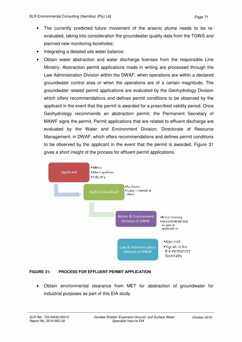
SLR Environmental Consulting (Namibia) (Pty) Ltd
SLR Ref. 733.04040.00010 Report No. 2016-WG-28
Dundee Smelter Expansion Ground- and Surface Water Specialist Input to EIA
October 2016
Page 71
• The currently predicted future movement of the arsenic plume needs to be re-
evaluated, taking into consideration the groundwater quality data from the TGWS and
planned new monitoring boreholes;
• Integrating a detailed site water balance;
• Obtain water abstraction and water discharge licenses from the responsible Line
Ministry. Abstraction permit applications made in writing are processed through the
Law Administration Division within the DWAF, when operations are within a declared
groundwater control area or when the operations are of a certain magnitude. The
groundwater related permit applications are evaluated by the Geohydrology Division
which offers recommendations and defines permit conditions to be observed by the
applicant in the event that the permit is awarded for a prescribed validity period. Once
Geohydrology recommends an abstraction permit, the Permanent Secretary of
MAWF signs the permit. Permit applications that are related to effluent discharge are
evaluated by the Water and Environment Division, Directorate of Resource
Management, in DWAF, which offers recommendations and defines permit conditions
to be observed by the applicant in the event that the permit is awarded. Figure 31
gives a short insight of the process for effluent permit applications.
FIGURE 31: PROCESS FOR EFFLUENT PERMIT APPLICATION
• Obtain environmental clearance from MET for abstraction of groundwater for
industrial purposes as part of this EIA study.
SLR Environmental Consulting (Namibia) (Pty) Ltd
SLR Ref. 733.04040.00010 Report No. 2016-WG-28
Dundee Smelter Expansion Ground- and Surface Water Specialist Input to EIA
October 2016
Page 72
• Consider compiling all data / results from above into a comprehensive new
groundwater model.
UNSIGNED ELECTRONIC COPY
Jonathan Church
(Project Author)
UNSIGNED ELECTRONIC COPY
Gwendal Madec
(Project Manager)
UNSIGNED ELECTRONIC COPY
Piet Smit
(Project Author)
UNSIGNED ELECTRONIC COPY
Arnold Bittner
(Approved Reviewer)
UNSIGNED ELECTRONIC COPY
Paul Klimczak
(Approved Reviewer)

SLR Environmental Consulting (Namibia) (Pty) Ltd
SLR Ref. 733.04040.00010 Report No. 2016-WG-28
Dundee Smelter Expansion Ground- and Surface Water Specialist Input to EIA
October 2016
Page 73
7 REFERENCES
AURECON (2013) Dundee Precious Metals Tsumeb, Storm Water Assessment Study Final
Report, 25th September 2013, Ref 109185 Document ID 7575
AURECON (2013) Water Management System : Dundee Precious Metals, Stormwater
Management :Options Report, 22nd October 2013, Ref 109185 Document ID 7575
CRERAR S., CHURCH J.(1988) : Evaporation Map for South West Africa/Namibia, Department
of Water Affairs South West Africa/Namibia, Report No.: 11/1/8/1/H1
DUNDEE PRECIOUS METALS TSUMEB (2016): DPMT Report #17 to the MET Technical
Committee – 2015/2016, February 2016.
DUNDEE PRECIOUS METALS TSUMEB (2016): Community Campaign / Project Report
Evaluation of Quality of Drinking Water Samples obtained from the Ondundu Community,
Tsumeb, June 2016, Document no. DPMT(ENV)-2016-001-CS .
DWA 1991 : THE WATER ACT (ACT 54 OF 1956), “The Namibian National Water Quality
Standards”, Department of Water Affairs, Ministry of Agriculture, Water and Rural
Development, Government of the Republic of Namibia.
GCS WATER AND ENVIRONMENTAL CONSULTANTS (2013): NCS Groundwater Data Review and
Monitoring, May 2013, Version Final. Client reference no. PO 00008185
GCS WATER AND ENVIRONMENTAL CONSULTANTS (2013): NCS Groundwater Flow and
Transport Model, July 2013, Version 1. Client reference no. PO 00008185
GCS WATER AND ENVIRONMENTAL CONSULTANTS (2014): Draft report, Tsumeb Water Supply
and Smelter Studies Phase 4: Smelter Sinkhole Risk and Contaminant Plume Mapping
Model, December 2014, Version 1. Client reference no. GCS 13-050.
GCS WATER AND ENVIRONMENTAL CONSULTANTS (2015): Memo: DPMT – Development of a
Groundwater Monitoring Programme, November 2015.
GCS WATER AND ENVIRONMENTAL CONSULTANTS (2016): Memo: Sampling Frequency and
Constituents analysed, February 2016.
GCS WATER AND ENVIRONMENTAL CONSULTANTS (2016): Tsumeb Smelter Groundwater
Model Update, March 2016, Report 1
GCS WATER AND ENVIRONMENTAL CONSULTANTS (2016): Dundee Precious Metals Tsumeb
Semlter Sampling Protocol, April 2016, Report Version – Draft.

SLR Environmental Consulting (Namibia) (Pty) Ltd
SLR Ref. 733.04040.00010 Report No. 2016-WG-28
Dundee Smelter Expansion Ground- and Surface Water Specialist Input to EIA
October 2016
Page 74
GKW Consult / BICON (2003): Tsumeb Groundwater Study - Final Report Volume 1: Main
Report. Consultant’s report to DWAF, File No. 12/1/2/16/2, Windhoek.
GOLDER ASSOCIATES AFRICA (PTY) LTD (2013): Dundee Precious Metals Tsumeb: Closure
Plan, November 2013, Report No. : 13614914 - 12263 - 1
GOLDER ASSOCIATES AFRICA (PTY) LTD (2013) : Dundee Precious Metals Tsumeb,
Environmental and Social Impact Assessment (ESIA) for New Sulphuric Acid Plant, Tsumeb,
Namibia, September 2013, Report No. : 12614527-11837-1
MENDELSOHN, J., JARVIS, A., ROBERTS, C. AND ROBERTS, T., (2002) : “Atlas of Namibia: A
portrait of the land and its people". David Philip Publishers, Cape Town, RSA.
MILLER, R. (2008) : The Geology of Namibia. Volume 1-3, The Geological Survey of Namibia,
Windhoek, Namibia.
SLR ENVIRONMENTAL CONSULTING (NAMIBIA) (PTY) LTD (2014) : Scoping Report for Dundee
Precious Metals Tsumeb’s Sewage Treatment Options, February 2014, Report No.
734.04040.00001
SLR ENVIRONMENTAL CONSULTING (NAMIBIA) (PTY) LTD (2014) : Scoping Report (including
impact assessment) for the proposed 11kV Power line for Dundee Precious Metals, March
2014, Report No. 734.04040.00001
SLR ENVIRONMENTAL CONSULTING (NAMIBIA) (PTY) LTD (2015) : Tsumeb Smelter Complex,
Environmental Management Plan for the DPMT Hazardous Water Disposal Site, April 2015,
Report No. 7NA04040.00004/001
SLR ENVIRONMENTAL CONSULTING (NAMIBIA) (PTY) LTD (2016): Scoping Report as part of an
EIA Amendment Process for the Proposed Upgrading and Optimisation of the Tsumeb
Smelter, July 2016, Report No. Report No. 1
SYNERGISTICS ENVIRONMENTAL SERVICES (2009) : Preliminary Assessment of the
Contamination Risk to the Groundwater regime at the Tsumeb Smelter, December 2009,
Revision 2, Report No. JW181/09/C391
SYNERGISTICS ENVIRONMENTAL SERVICES (2011) : Environmental Assessment for the
Tsumeb Smelter, Environmental Management Plan, December 2011, Report No.
N0259/EMP01
WORLEY PARSONS (2015) : Tsumeb Smelter Expansion PFS Final Report, August 2015,
Report no. 207040-00149 – 00-PM-REP-0001.
WHO (2011) : WHO Guidelines for Drinking-water Quality (fourth edition). World Health
Organisation 2011. ISBN: 978 92 4 154815 1

SLR Environmental Consulting (Namibia) (Pty) Ltd
SLR Ref. 733.04040.00010 Report No. 2016-WG-28
Dundee Smelter Expansion Ground- and Surface Water Specialist Input to EIA
October 2016
Page 75

SLR Environmental Consulting (Namibia) (Pty) Ltd
SLR Ref. 733.04040.00010 Report No. 2016-WG-28
Dundee Smelter Expansion Ground- and Surface Water Specialist Input to EIA
October 2016
Page 76
8 APPENDICES
APPENDIX 1: WATER QUALITY GUIDELINES (DWAF, 1988)

SLR Environmental Consulting (Namibia) (Pty) Ltd
SLR Ref. 733.04040.00010 Report No. 2016-WG-28
Dundee Smelter Expansion Ground- and Surface Water Specialist Input to EIA
October 2016
Page 77
Namibia, Department of Water Affairs
Guidelines for the evaluation of drinking-water
for human consumption with regard to chemical,
physical and bacteriological quality
20 October 1988
Parameters Group A Group B Group C Group D
and Excellent Good Low Health Unsuitable
Expression of the results Quality Quality Risk
A. PHYSICO-CHEMICAL PARAMETERS
Temperature T °C - - - -
Hydrogen ion pH pH 6.0 to 9.0 5.5 to 9.5 4.0 to 11.0 4.0 to 11.0
concentration unit
Conductivity EC mS/m 150 300 400 400
at 25 °C - - - -
Total dissolved TDS mg/l - - - -
solids
Dissolved % O2 mg/l - - - -
oxygen saturation
Chlorides Cl mg/l 250 600 1300 1300
Sulphates SO4 mg/l 200 600 1200 1200
Total Hardness CaCO3 mg/l 300 650 1200 1200
Calcium Ca mg/l 150 200 400 400
CaCO3 mg/l 375 500 1000 1000
Magnesium Mg mg/l 70 100 200 200
CaCO3 mg/l 290 420 840 840
Sodium Na mg/l 100 400 800 800
Potassium K mg/l 200 400 800 800
Aluminium Al µg/l 150 500 1000 1000
B. PARAMETERS CONCERNING SUBSTANCES UNDESIRABLE IN EXCESSIVE AMOUNTS
Nitrates NO3 mg/l 45 90 180 180
N mg/l 10 20 40 40
Nitrites NO2 mg/l - - - -
Ammonium NH4 mg/l 1.5 2.5 5 5
N mg/l 1 2 4 4
Fluoride F mg/l 1.5 2.0 3.0 3.0
mg/l - - - -
Hydrogen H2S µg/l 100 300 600 600
sulphide
Phosphorus P2O5 µg/l - - - -
PO4 µg/l - - - -
Boron B µg/l 500 2000 4000 4000
Iron Fe µg/l 100 1000 2000 2000
Manganese Mn µg/l 50 1000 2000 2000
Copper Cu µg/l 500 1000 2000 2000
after 12 hours in pipe µg/l - - - -
Zinc Zn µg/l 1000 5000 10000 10000
after 12 hours in pipe µg/l - - - -
Cobalt Co µg/l 250 500 1000 1000
Barium Ba µg/l 500 1000 2000 2000
Silver Ag µg/l 20 50 100 100
C. PARAMETERS CONCERNING TOXIC SUBSTANCES
Arsenic As µg/l 100 300 600 600
Beryllium Be µg/l 2 5 10 10
Cadmium Cd µg/l 10 20 40 40
Cyanides CN µg/l 200 300 600 600
Chromium Cr µg/l 100 200 400 400
Mercury Hg µg/l 5 10 20 20
Nickel Ni µg/l 250 500 1000 1000
Lead Pb µg/l 50 100 200 200
Antimony Sb µg/l 50 100 200 200
Selenium Se µg/l 20 50 100 100
Vanadium V µg/l 250 500 1000 1000
D. FURTHER PARAMETERS
Bismuth Bi µg/l 250 500 1000 1000
Bromine Br µg/l 1000 3000 6000 6000
Cerium Ce µg/l 1000 2000 4000 4000
Gold Au µg/l 2 5 10 10
Iodine I µg/l 500 1000 2000 2000
Lithium Li µg/l 2500 5000 10000 10000
Tellurium Te µg/l 2 5 10 10
Thallium Tl µg/l 5 10 20 20
Tin Sn µg/l 100 200 400 400
Titanium Ti µg/l 100 500 1000 1000
Tungsten W µg/l 100 500 1000 1000
Uranium U µg/l 1000 4000 8000 8000

SLR Environmental Consulting (Namibia) (Pty) Ltd
SLR Ref. 733.04040.00010 Report No. 2016-WG-28
Dundee Smelter Expansion Ground- and Surface Water Specialist Input to EIA
October 2016
Page 78
APPENDIX 2: MET. OFFICE RAINFALL DATA FOR TSUMEB AREA (mm)
Gaikos (Met. Office No. 1056 7174)
Gaikos
10567174Jan Feb Mar Apr May Jun Jul Aug Sep Oct Nov Dec
Gaikos
Annual
Rainfall
(mm)
1986 129 64.9 265 0 0 0 0 0 5.7 89.1 50 24.6 628.3
1987 72.3 169.8 27 27.5 0 0 1.8 0 0 13 34.7 231.5 577.6
1988 50 75.1 38.3 46.5 0 0 0 0 0 0 45 193.4 448.3
1989 77.1 195.1 20 104 0 0 0 0 0 6.5 30 36 468.7
1990 215.1 19.6 127 13.5 0 0 0 0 0 39.3 15.1 58.6 488.2
1991 148 102 63.5 0 0 0 0 0 3.8 2.7 51 171 542.0
1992 143.1 30 77.5 0.1 0 0 0 0 14 4.9 28.9 21 319.5
1993 80.3 94.8 44.3 33.5 4 0 0 0 0 45.3 65.5 49.7 417.4
1994 287.3 128.8 20 5 0 0 0 0 0 1.7 83.9 3.5 530.2
1995 30 60 74.9 0 15 2 0 0 7.5 29 27.3 25.5 271.2
1996 159.3 121.3 26.2 15.5 0 0 0 0 0 3.5 24.3 118.3 468.4
1997 241.8 124.5 88.7 10 0 0 0 0.1 48.1 44 6.5 84.6 648.3
1998 62 17.5 6 77 0 0 0 0 0 20.6 14.9 115.6 313.6
1999 112.4 37.5 98.6 0 3.5 0 0 0 12 0.8 51.8 165.6 482.2
2000 107.2 170.5 94.8 11.3 10 0 0 0 0 38.4 22.6 62 516.8
2001 36.5 86 105.5 37.9 6.3 0 0 0 50 0 47.2 15.5 384.9
2002 116.5 81.7 150.5 10.5 0 0 0 0 0 13 95 79.5 546.7
2003 73.3 76.5 39.7 0 LR 1 0 0 1 19.5 57.5 1.5 270.0
2004 132.4 75.6 97.1 197 0 0 0 0 0 66.1 31.1 31.2 630.5
2005 99.7 63 39 54.5 0 0 0 0 0 3 51.5 61.7 372.4
2006 342.5 LR 122.5 5.5 19.3 0 0 0 1.5 28.5 43.5 89.5 652.8
2007 120.5 31.5 20.5 29 0 0 0 0 0 24 63.8 79 368.3
2008 203.1 138.9 92.4 0.1 1 0 0 0 0 0 101.2 20 556.7
2009 230.4 158.5 95.7 3.5 29.3 0.4 0 0 10 23.6 23.1 1.8 576.3
2010 144 52.6 90.9 29 LR LR LR LR LR LR LR 49 -
2011 LR LR 196 LR 11 0 LR LR LR LR 110 LR -
2012 180.2 143.3 87.2 6.5 0 0 0 0 0 25 63.5 54.2 559.9
2013 92 32 37.7 0 1.5 0 0 0 0 2.7 145.5 311.4
2014 16.3 215.5 126.9 51.1 LR 0 LR 0 2 30.2 112 44.8 598.8
2015 9.6 13 90.7 18.4 0 0 0 0 0.5 LR LR LR -
Mean 128.0 92.1 82.1 27.1 3.7 0.1 0.1 0.0 5.6 21.3 50.0 72.6 479.6
Max 342.5 215.5 265 197 29.3 2 1.8 0.1 50 89.1 112 231.5 652.8
Median 116.5 79.1 87.95 11.3 0 0 0 0 0 19.5 47.2 56.4 488.2
Yellow highlight in last column indicates no annual rainfall value calculated due to Lost Record

SLR Environmental Consulting (Namibia) (Pty) Ltd
SLR Ref. 733.04040.00010 Report No. 2016-WG-28
Dundee Smelter Expansion Ground- and Surface Water Specialist Input to EIA
October 2016
Page 79
Choantsas (Met. Office No. 1104 2024)
Choantsas
11042024Jan Feb Mar Apr May Jun Jul Aug Sep Oct Nov Dec
Choantsas
Annual
Rainfall
(mm)
1986 52.0 139.0 103.0 38.0 0.0 1.0 0.0 0.0 16.0 66.0 34.5 9.5 459.0
1987 30.5 97.5 38.5 25.0 1.0 0.0 6.0 0.0 0.0 9.0 17.5 101.0 326.0
1988 58.5 25.0 67.5 35.5 0.0 0.0 0.0 0.0 0.0 4.5 15.5 127.0 333.5
1989 188.5 247.0 0.0 73.5 5.0 0.0 0.0 0.0 0.0 0.5 0.0 18.0 532.5
1990 184.0 44.5 74.0 7.5 0.0 0.0 0.0 0.0 0.0 0.0 18.5 77.5 406.0
1991 187.0 134.0 35.0 0.0 0.0 0.0 0.0 0.0 0.2 19.5 55.0 116.5 547.2
1992 70.5 9.5 66.5 6.0 0.0 0.0 0.0 0.0 17.1 0.1 43.0 38.0 250.7
1993 113.0 128.5 57.5 25.0 0.0 0.0 0.0 0.0 0.0 40.0 128.5 106.5 599.0
1994 218.0 125.0 21.5 0.0 0.0 0.0 0.0 0.0 0.0 3.0 52.5 1.5 421.5
1995 9.0 52.5 44.0 0.0 29.0 4.0 0.0 0.0 3.0 0.0 22.5 130.5 294.5
1996 171.5 106.5 4.0 0.0 0.0 0.0 0.0 0.0 0.0 0.0 35.0 125.0 442.0
1997 -
1998 86.5 70.5 6.0 15.0 0.0 0.0 0.0 0.0 0.0 10.0 4.0 31.2 223.2
1999 166.0 47.5 116.0 5.0 0.0 0.0 0.0 0.0 2.0 14.5 39.5 242.6 633.1
2000 102.0 144.0 87.5 45.5 34.0 0.0 0.0 0.0 0.0 12.0 5.0 72.5 502.5
2001 56.5 207.4 52.0 133.0 0.0 0.0 0.0 0.0 86.0 0.0 42.0 35.0 611.9
2002 25.0 92.0 45.5 13.0 LR LR LR LR LR LR LR LR -
2003 71.0 102.0 16.0 9.5 0.0 0.0 0.0 0.0 0.0 60.0 81.5 54.0 394.0
2004 112.0 84.5 89.0 87.0 0.0 0.0 0.0 0.0 0.0 8.5 18.5 33.0 432.5
2005 LR 101.0 62.0 47.0 0.0 0.0 0.0 0.0 0.0 0.0 52.0 52.0 314.0
2006 176.5 230.5 78.0 0.0 0.0 0.0 0.0 0.0 0.0 40.5 68.5 31.0 625.0
2007 88.0 28.5 25.5 8.0 0.0 0.0 0.0 0.0 0.0 30.5 34.0 80.8 295.3
2008 246.0 151.0 199.5 0.0 0.0 0.0 0.0 0.0 0.0 0.0 209.0 35.7 841.2
2009 122.5 155.5 80.0 0.0 6.5 8.5 0.0 0.0 8.5 29.0 128.5 72.0 611.0
2010 LR LR LR 44.0 LR LR LR LR LR LR LR LR -
2011 271.0 81.0 201.5 79.5 25.0 0.0 0.0 0.0 0.0 0.2 52.0 107.5 817.7
2012 148.5 239.5 134.5 28.0 0.0 LR LR 0.0 0.0 37.0 46.0 161.5 795.0
2013 26.5 20.0 25.0 0.0 0.0 0.0 0.0 0.0 0.0 0.0 27.5 159.5 258.5
2014 62.6 141.5 201.0 59.0 0.0 0.0 0.0 0.0 0.0 21.5 51.3 63.1 600.0
2015 31.5 41.0 71.0 24.5 0.0 0.0 0.0 0.0 0.0 9.5 LR LR -
Mean 113.9 108.8 71.5 27.9 3.7 0.5 0.2 0.0 4.9 15.4 49.3 80.1 483.3
Max 271.0 247.0 201.5 133.0 34.0 8.5 6.0 0.0 86.0 66.0 209.0 242.6 841.2
Median 102.0 101.5 64.3 15.0 0.0 0.0 0.0 0.0 0.0 9.0 40.8 72.3 450.5
Yellow highlight in last column indicates no annual rainfall value calculated due to Lost Record
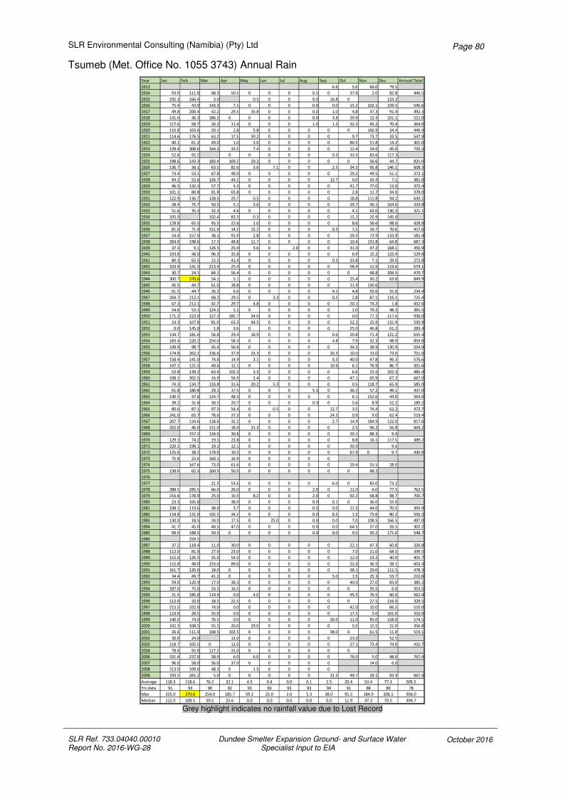
SLR Environmental Consulting (Namibia) (Pty) Ltd
SLR Ref. 733.04040.00010 Report No. 2016-WG-28
Dundee Smelter Expansion Ground- and Surface Water Specialist Input to EIA
October 2016
Page 80
Tsumeb (Met. Office No. 1055 3743) Annual Rain
Year Jan Feb Mar Apr May Jun Jul Aug Sep Oct Nov Dec Annual Total
1913 6.6 5.6 66.0 79.5
1914 93.0 111.8 68.3 50.5 0 0 0 0.5 0 37.6 2.0 82.8 446.5
1915 192.3 166.4 3.0 0.5 0 0 0.0 16.8 0 124.2
1916 75.4 43.9 143.3 7.1 0 0 0 0.0 0.0 15.2 102.1 159.5 546.6
1917 49.8 200.4 42.2 29.5 35.8 0 0 0.0 1.0 4.8 37.3 91.4 492.3
1918 141.0 36.3 186.2 0 0 0 0 0.0 3.8 39.9 12.4 101.1 521.0
1919 117.6 58.7 26.2 11.4 0 0 0 1.0 1.3 32.3 45.2 70.4 364.0
1920 116.8 103.6 20.1 2.8 5.8 0 0 0 0 0 166.9 24.4 440.4
1921 114.6 176.5 63.2 17.5 59.2 0 0 0 0 9.7 73.7 33.5 547.9
1922 40.1 61.2 49.0 1.0 3.0 0 0 0 0 80.5 51.8 14.2 301.0
1923 139.4 308.6 164.3 33.5 7.4 0 0 0 0 12.4 24.6 45.0 735.3
1924 52.6 92.2 0 0 0 0 0 0.5 33.5 83.6 117.3
1925 198.6 143.3 183.4 169.2 29.2 0 0 0 0 0 56.6 44.7 825.0
1926 136.7 36.1 63.5 82.6 3.6 7.1 0 0 2.5 34.5 95.8 146.1 608.3
1927 73.4 53.1 67.8 48.0 0 0 0 0 0 29.2 49.5 51.1 372.1
1928 94.2 52.6 126.7 44.2 0 0 0 0 12.7 0.0 43.4 7.1 381.0
1929 46.5 132.3 57.7 4.3 0 0 0 0 0 41.7 77.0 13.0 372.4
1930 101.1 80.8 81.8 65.8 0 0 0 0 0 2.8 11.7 34.0 378.0
1931 122.9 136.7 128.5 25.7 0.5 0 0 0 0 18.8 111.8 94.2 639.1
1932 28.4 75.7 50.5 5.1 3.6 0 0 0 0 29.7 36.1 104.6 333.8
1933 51.6 35.3 32.3 4.6 0 0 0 0 0 4.1 63.0 130.3 321.1
1934 335.0 102.4 83.3 0.3 0 0 0 0 15.2 25.9 145.0
1935 129.8 65.5 45.5 22.6 2.0 0 0 0 0 8.6 56.6 98.0 428.8
1936 81.0 71.9 151.9 14.2 15.2 0 0 0 0.5 1.5 10.7 70.6 417.6
1937 54.4 157.0 38.1 91.9 2.8 0 0 0 0 29.5 73.9 133.9 581.4
1938 204.0 198.6 17.3 48.8 11.7 0 0 0 0 10.4 131.8 64.8 687.3
1939 37.3 9.1 126.5 25.9 3.6 0 2.0 0 0 31.0 47.2 168.1 450.9
1940 193.8 48.0 96.3 35.8 0 0 0 0 0 6.9 15.2 133.9 529.8
1941 80.3 65.5 15.5 41.4 0 0 0 0 0.3 33.8 7.1 29.0 272.8
1942 103.9 141.5 213.4 25.4 0 0 0 0 0 58.4 11.9 119.6 674.1
1943 30.7 24.1 84.1 56.4 0 0 0 0 0 0 68.8 206.5 470.7
1944 300.7 370.6 54.1 5.1 0 0 0 0 0 25.4 30.2 63.8 849.9
1945 45.5 44.7 61.0 18.8 0 0 0 0 0 11.9 130.6
1946 61.5 44.7 26.2 6.6 0 0 0 0 4.1 4.8 55.6 31.0 234.4
1947 204.7 213.1 68.3 29.5 0 3.3 0 0 0.5 2.8 87.1 116.1 725.4
1948 67.3 212.1 42.7 29.7 4.8 0 0 0 0 20.1 74.2 1.8 452.6
1949 54.6 53.1 124.2 5.1 0 0 0 0 0 1.0 79.2 48.3 365.5
1950 171.2 223.0 127.3 185.7 34.0 0 0 0 0 0.0 77.2 117.6 936.0
1951 24.3 107.8 81.0 63.3 44.5 0 0 0 0 52.2 25.9 131.9 530.9
1952 0.0 145.0 1.8 3.6 0 0 0 0 0 25.0 46.8 61.2 283.4
1953 134.7 181.6 56.8 29.4 18.9 0 0 0 0.6 20.8 71.4 121.2 635.4
1954 183.4 220.2 254.0 58.3 0 0 0 0 4.8 7.9 32.3 98.9 859.8
1955 149.9 98.7 45.4 56.6 0 0 0 0 0 34.5 38.9 130.9 554.9
1956 174.8 262.1 136.6 37.9 23.3 0 0 0 20.3 10.0 13.0 73.0 751.0
1957 158.4 141.0 74.8 14.9 3.1 0 0 0 0.3 40.0 47.8 96.3 576.6
1958 147.1 121.5 40.6 12.1 0 0 0 0 10.6 6.1 76.9 86.7 501.6
1959 52.8 139.2 63.4 102.3 3.3 0 0 0 0 6.6 15.5 102.3 485.4
1960 108.1 302.5 16.9 56.9 2.4 0 0 0 0 47.1 65.9 67.2 667.0
1961 74.3 134.7 133.8 31.6 20.2 5.3 0 0 0 0.5 118.7 65.9 585.0
1962 61.8 180.8 29.1 17.5 0 0 0 5.3 0 36.2 57.2 49.1 437.0
1963 140.5 47.8 124.7 48.3 0 0 0 0 0 6.1 152.6 44.0 564.0
1964 39.2 31.8 30.5 20.7 0 0 0 0.3 0 5.6 8.9 52.2 189.2
1965 80.6 87.1 97.3 54.4 0 0.5 0 0 12.7 3.5 74.4 62.2 472.7
1966 241.0 65.7 78.6 37.3 0 0 0 0 24.5 0.9 9.0 62.4 519.4
1967 207.7 124.6 128.6 32.2 0 0 0 0 2.7 14.9 184.9 122.0 817.6
1968 202.0 46.0 151.0 18.4 31.3 0 0 0 0 2.5 96.2 56.8 604.2
1969 157.2 134.0 30.8 0 0 0 0 0 20.1 88.3 9.4
1970 129.3 74.2 19.5 23.8 0 0 0 0 0 8.8 16.1 117.5 389.2
1971 220.1 198.1 19.1 12.1 0 0 0 0 0 30.0 9.6
1972 125.6 38.2 179.0 10.5 0 0 0 0 0 67.9 0 9.7 430.9
1973 75.8 22.6 160.1 16.9 0 0 0 0 0
1974 167.6 73.0 61.6 0 0 0 0 0 29.4 55.5 28.0
1975 158.0 62.3 160.5 50.5 0 0 0 0 0 0 68.2
1976
1977 21.5 53.6 0 0 0 0 6.0 0 83.0 73.2
1978 288.5 285.5 66.0 26.0 0 0 0 2.0 0 11.0 6.0 77.5 762.5
1979 216.6 178.9 25.0 10.3 8.2 0 0 2.0 0 92.2 68.8 98.7 700.7
1980 23.3 165.8 38.0 0 0 0 0.0 0.1 0 36.0 55.0
1981 108.1 119.6 38.0 3.7 0 0 0 0.5 0.0 11.5 44.0 70.5 395.9
1982 118.8 131.0 102.5 34.2 0 0 0 0.0 8.5 1.5 73.6 80.2 550.3
1983 130.0 18.5 24.0 17.5 0 25.0 0 0.0 0.0 7.0 108.5 166.5 497.0
1984 41.7 45.0 40.5 47.0 0 0 0 0.0 0.0 64.5 37.0 26.5 302.2
1985 99.0 188.5 50.5 0 0 0 0 0.0 0.0 9.5 30.2 171.0 548.7
1986 259.5
1987 37.2 118.4 11.0 30.0 0 0 0 0 0 22.1 47.3 60.8 326.8
1988 112.0 81.0 27.0 23.0 0 0 0 0 0 7.0 21.0 68.5 339.5
1989 115.0 126.5 35.0 54.0 0 0 0 0 0 12.0 23.2 40.0 405.7
1990 115.8 48.0 233.0 89.0 0 0 0 0 0 22.0 36.5 58.1 602.4
1991 161.7 120.0 18.0 0 0 0 0 0 0 38.1 29.0 111.5 478.3
1992 34.4 49.7 41.2 0 0 0 0 0 5.0 1.5 25.3 53.7 210.8
1993 59.0 120.9 17.0 38.3 0 0 0 0 0 40.0 27.0 83.0 385.2
1994 187.0 75.0 33.5 16.5 0 0 0 0 0 0 35.5 6.0 353.5
1995 21.5 185.0 119.9 0.0 4.0 0 0 0 0 95.5 76.5 60.0 562.4
1996 112.0 33.0 18.5 22.5 0 0 0 0 0 0 27.5 116.0 329.5
1997 215.5 102.0 74.0 0.0 0 0 0 0 0 42.0 10.0 66.5 510.0
1998 123.0 28.5 35.0 0.0 0 0 0 0 0 17.5 5.0 101.0 310.0
1999 140.0 74.0 76.5 0.0 0 0 0 0 20.0 11.0 95.0 158.0 574.5
2000 102.3 108.5 55.5 20.0 29.0 0 0 0 0 5.0 15.5 21.0 356.8
2001 26.6 111.0 168.5 102.5 0 0 0 0 38.0 0 61.5 11.0 519.1
2002 30.0 24.0 12.0 0 0 0 0 0 23.0 52.5
2003 118.7 105.5 0 12.0 0 0 0 0 0 27.1 73.4 74.0 410.7
2004 78.0 92.0 117.2 31.0 0 0 0 0 0 0
2006 331.4 237.0 58.0 6.0 6.0 0 0 0 0 76.0 5.0 48.0 767.4
2007 96.0 58.0 56.0 37.0 0 0 0 0 0 14.0 6.0
2008 213.0 109.0 48.3 0 1.5 0 0 0 0
2009 193.5 265.2 5.0 0 0 0 0 0 31.5 49.7 29.1 93.4 667.4
Average 118.3 118.6 76.2 32.1 4.5 0.4 0.0 0.1 2.5 20.4 53.4 77.3 505.5
Yrs data 91 93 90 92 93 93 93 93 94 91 88 89 78
Max 335.0 370.6 254.0 185.7 59.2 25.0 2.0 5.3 38.0 95.5 184.9 206.5 936.0
Median 112.0 108.5 59.5 25.6 0.0 0.0 0.0 0.0 0.0 11.9 47.3 70.5 494.7 Grey highlight indicates no rainfall value due to Lost Record

SLR Environmental Consulting (Namibia) (Pty) Ltd
SLR Ref. 733.04040.00010 Report No. 2016-WG-28
Dundee Smelter Expansion Ground- and Surface Water Specialist Input to EIA
October 2016
Page 81
Tsumeb (Met. Office No. 1055 3743) Seasonal Rain
Year Oct Nov Dec Jan Feb Mar Apr May Jun Jul Aug Sep Annual Total
1913 6.6
1913/14 5.6 66.0 79.5 93.0 111.8 68.3 50.5 0 0 0 0.5 0 475.2
1914/15 37.6 2.0 82.8 192.3 166.4 3.0 0.5 0 0 0.0 16.8 501.4
1915/16 0 124.2 75.4 43.9 143.3 7.1 0 0 0 0.0 0.0 393.9
1916/17 15.2 102.1 159.5 49.8 200.4 42.2 29.5 35.8 0 0 0.0 1.0 635.5
1917/18 4.8 37.3 91.4 141.0 36.3 186.2 0 0 0 0 0.0 3.8 501.1
1918/19 39.9 12.4 101.1 117.6 58.7 26.2 11.4 0 0 0 1.0 1.3 369.6
1919/20 32.3 45.2 70.4 116.8 103.6 20.1 2.8 5.8 0 0 0 0 397.0
1920/21 0 166.9 24.4 114.6 176.5 63.2 17.5 59.2 0 0 0 0 622.3
1921/22 9.7 73.7 33.5 40.1 61.2 49.0 1.0 3.0 0 0 0 0 271.2
1922/23 80.5 51.8 14.2 139.4 308.6 164.3 33.5 7.4 0 0 0 0 799.7
1923/24 12.4 24.6 45.0 52.6 92.2 0 0 0 0 0 0.5 227.3
1924/25 33.5 83.6 117.3 198.6 143.3 183.4 169.2 29.2 0 0 0 0 958.1
1925/26 0 56.6 44.7 136.7 36.1 63.5 82.6 3.6 7.1 0 0 2.5 433.4
1926/27 34.5 95.8 146.1 73.4 53.1 67.8 48.0 0 0 0 0 0 518.7
1927/28 29.2 49.5 51.1 94.2 52.6 126.7 44.2 0 0 0 0 12.7 460.2
1928/29 0.0 43.4 7.1 46.5 132.3 57.7 4.3 0 0 0 0 0 291.3
1929/30 41.7 77.0 13.0 101.1 80.8 81.8 65.8 0 0 0 0 0 461.2
1930/31 2.8 11.7 34.0 122.9 136.7 128.5 25.7 0.5 0 0 0 0 462.8
1931/32 18.8 111.8 94.2 28.4 75.7 50.5 5.1 3.6 0 0 0 0 388.1
1932/33 29.7 36.1 104.6 51.6 35.3 32.3 4.6 0 0 0 0 0 294.2
1933/34 4.1 63.0 130.3 335.0 102.4 83.3 0.3 0 0 0 0 718.4
1934/35 15.2 25.9 145.0 129.8 65.5 45.5 22.6 2.0 0 0 0 0 451.5
1935/36 8.6 56.6 98.0 81.0 71.9 151.9 14.2 15.2 0 0 0 0.5 497.9
1936/37 1.5 10.7 70.6 54.4 157.0 38.1 91.9 2.8 0 0 0 0 427.0
1937/38 29.5 73.9 133.9 204.0 198.6 17.3 48.8 11.7 0 0 0 0 717.7
1938/39 10.4 131.8 64.8 37.3 9.1 126.5 25.9 3.6 0 2.0 0 0 411.4
1939/40 31.0 47.2 168.1 193.8 48.0 96.3 35.8 0 0 0 0 0 620.2
1940/41 6.9 15.2 133.9 80.3 65.5 15.5 41.4 0 0 0 0 0.3 359.0
1941/42 33.8 7.1 29.0 103.9 141.5 213.4 25.4 0 0 0 0 0 554.1
1942/43 58.4 11.9 119.6 30.7 24.1 84.1 56.4 0 0 0 0 0 385.2
1943/44 0 68.8 206.5 300.7 370.6 54.1 5.1 0 0 0 0 0 1 005.8
1944/45 25.4 30.2 63.8 45.5 44.7 61.0 18.8 0 0 0 0 0 289.4
1945/46 11.9 130.6 61.5 44.7 26.2 6.6 0 0 0 0 4.1 285.6
1946/47 4.8 55.6 31.0 204.7 213.1 68.3 29.5 0 3.3 0 0 0.5 610.8
1947/48 2.8 87.1 116.1 67.3 212.1 42.7 29.7 4.8 0 0 0 0 562.6
1948/49 20.1 74.2 1.8 54.6 53.1 124.2 5.1 0 0 0 0 0 333.1
1949/50 1.0 79.2 48.3 171.2 223.0 127.3 185.7 34.0 0 0 0 0 869.7
1950/51 0.0 77.2 117.6 24.3 107.8 81.0 63.3 44.5 0 0 0 0 515.7
1951/52 52.2 25.9 131.9 0.0 145.0 1.8 3.6 0 0 0 0 0 360.4
1952/53 25.0 46.8 61.2 134.7 181.6 56.8 29.4 18.9 0 0 0 0.6 555.0
1953/54 20.8 71.4 121.2 183.4 220.2 254.0 58.3 0 0 0 0 4.8 934.1
1954/55 7.9 32.3 98.9 149.9 98.7 45.4 56.6 0 0 0 0 0 489.7
1955/56 34.5 38.9 130.9 174.8 262.1 136.6 37.9 23.3 0 0 0 20.3 859.3
1956/57 10.0 13.0 73.0 158.4 141.0 74.8 14.9 3.1 0 0 0 0.3 488.5
1957/58 40.0 47.8 96.3 147.1 121.5 40.6 12.1 0 0 0 0 10.6 516.0
1958/59 6.1 76.9 86.7 52.8 139.2 63.4 102.3 3.3 0 0 0 0 530.7
1959/60 6.6 15.5 102.3 108.1 302.5 16.9 56.9 2.4 0 0 0 0 611.2
1960/61 47.1 65.9 67.2 74.3 134.7 133.8 31.6 20.2 5.3 0 0 0 580.1
1961/62 0.5 118.7 65.9 61.8 180.8 29.1 17.5 0 0 0 5.3 0 479.6
1962/63 36.2 57.2 49.1 140.5 47.8 124.7 48.3 0 0 0 0 0 503.8
1963/64 6.1 152.6 44.0 39.2 31.8 30.5 20.7 0 0 0 0.3 0 325.2
1964/65 5.6 8.9 52.2 80.6 87.1 97.3 54.4 0 0.5 0 0 12.7 399.3
1965/66 3.5 74.4 62.2 241.0 65.7 78.6 37.3 0 0 0 0 24.5 587.2
1966/67 0.9 9.0 62.4 207.7 124.6 128.6 32.2 0 0 0 0 2.7 568.1
1967/68 14.9 184.9 122.0 202.0 46.0 151.0 18.4 31.3 0 0 0 0 770.5
1968/69 2.5 96.2 56.8 157.2 134.0 30.8 0 0 0 0 0 477.5
1969/70 20.1 88.3 9.4 129.3 74.2 19.5 23.8 0 0 0 0 0 364.6
1970/71 8.8 16.1 117.5 220.1 198.1 19.1 12.1 0 0 0 0 0 591.8
1971/72 30.0 9.6 125.6 38.2 179.0 10.5 0 0 0 0 0 392.9
1972/73 67.9 0 9.7 75.8 22.6 160.1 16.9 0 0 0 0 0 353.0
1973/74 167.6 73.0 61.6 0 0 0 0 0 302.2
1974/75 29.4 55.5 28.0 158.0 62.3 160.5 50.5 0 0 0 0 0 544.2
1975/76 0 68.2 68.2
1976/77 21.5 53.6 0 0 0 0 6.0 81.1
1977/78 0 83.0 73.2 288.5 285.5 66.0 26.0 0 0 0 2.0 0 824.2
1978/79 11.0 6.0 77.5 216.6 178.9 25.0 10.3 8.2 0 0 2.0 0 535.5
1979/80 92.2 68.8 98.7 23.3 165.8 38.0 0 0 0 0.0 0.1 486.9
1980/81 0 36.0 55.0 108.1 119.6 38.0 3.7 0 0 0 0.5 0.0 360.9
1981/82 11.5 44.0 70.5 118.8 131.0 102.5 34.2 0 0 0 0.0 8.5 521.0
1982/83 1.5 73.6 80.2 130.0 18.5 24.0 17.5 0 25.0 0 0.0 0.0 370.3
1983/84 7.0 108.5 166.5 41.7 45.0 40.5 47.0 0 0 0 0.0 0.0 456.2
1984/85 64.5 37.0 26.5 99.0 188.5 50.5 0 0 0 0 0.0 0.0 466.0
1985/86 9.5 30.2 171.0 259.5 470.2
1986/87 37.2 118.4 11.0 30.0 0 0 0 0 0 196.6
1987/88 22.1 47.3 60.8 112.0 81.0 27.0 23.0 0 0 0 0 0 373.2
1988/89 7.0 21.0 68.5 115.0 126.5 35.0 54.0 0 0 0 0 0 427.0
1989/90 12.0 23.2 40.0 115.8 48.0 233.0 89.0 0 0 0 0 0 561.0
1990/91 22.0 36.5 58.1 161.7 120.0 18.0 0 0 0 0 0 0 416.3
1991/92 38.1 29.0 111.5 34.4 49.7 41.2 0 0 0 0 0 5.0 308.9
1992/93 1.5 25.3 53.7 59.0 120.9 17.0 38.3 0 0 0 0 0 315.7
1993/94 40.0 27.0 83.0 187.0 75.0 33.5 16.5 0 0 0 0 0 462.0
1994/95 0 35.5 6.0 21.5 185.0 119.9 0.0 4.0 0 0 0 0 371.9
1995/96 95.5 76.5 60.0 112.0 33.0 18.5 22.5 0 0 0 0 0 418.0
1996/97 0 27.5 116.0 215.5 102.0 74.0 0.0 0 0 0 0 0 535.0
1997/98 42.0 10.0 66.5 123.0 28.5 35.0 0.0 0 0 0 0 0 305.0
1998/99 17.5 5.0 101.0 140.0 74.0 76.5 0.0 0 0 0 0 20.0 434.0
1999/2000 11.0 95.0 158.0 102.3 108.5 55.5 20.0 29.0 0 0 0 0 579.3
2000/01 5.0 15.5 21.0 26.6 111.0 168.5 102.5 0 0 0 0 38.0 488.1
2001/02 0 61.5 11.0 30.0 24.0 12.0 0 0 0 0 0 138.5
2002/03 23.0 52.5 118.7 105.5 0 12.0 0 0 0 0 0 311.7
2003/04 27.1 73.4 74.0 78.0 92.0 117.2 31.0 0 0 0 0 0 492.7
2004/05 0
2005/06 331.4 237.0 58.0 6.0 6.0 0 0 0 0 638.4
2006/07 76.0 5.0 48.0 96.0 58.0 56.0 37.0 0 0 0 0 0 376.0
2007/08 14.0 6.0 213.0 109.0 48.3 0 1.5 0 0 0 0 391.8
2008/09 193.5 265.2 5.0 0 0 0 0 0 31.5 495.2
Tsumeb Monthly Rainfall Information as Seasonal Totals
Grey highlight indicates no rainfall value due to Lost Record

SLR Environmental Consulting (Namibia) (Pty) Ltd
SLR Ref. 733.04040.00010 Report No. 2016-WG-28
Dundee Smelter Expansion Ground- and Surface Water Specialist Input to EIA
October 2016
Page 82
Otjirukaku (Met. Office No. 1009 8526)
Otjirukaku
10098526Jan Feb Mar Apr May Jun Jul Aug Sep Oct Nov Dec
Otjirukaku
Annual
Rainfall
(mm)
1986 55.5 115.0 121.5 85.0 0.0 0.0 0.0 0.0 25.0 49.5 33.0 18.5 503.0
1987 36.0 147.5 91.0 69.0 0.0 0.0 0.0 0.0 0.0 55.0 41.0 87.5 527.0
1988 76.0 86.5 95.0 57.0 0.0 0.0 0.0 0.0 0.0 8.5 42.0 65.0 430.0
1989 226.0 252.0 26.5 105.5 1.5 0.0 0.0 0.0 0.0 4.5 10.0 10.0 636.0
1990 100.0 74.0 130.5 53.5 0.0 0.0 0.0 0.0 0.0 22.5 22.5 111.0 514.0
1991 95.0 169.0 105.5 0.0 0.0 0.0 0.0 0.0 0.6 35.5 40.0 101.5 547.1
1992 63.5 18.5 63.0 0.0 0.0 0.0 0.0 0.0 10.0 19.5 37.0 37.0 248.5
1993 97.0 186.0 45.0 24.0 0.0 0.0 0.0 5.0 0.0 34.0 136.5 50.0 577.5
1994 341.8 91.0 25.5 3.0 0.0 0.0 0.0 0.0 0.0 0.0 38.5 30.0 529.8
1995 12.3 101.0 41.0 0.0 8.0 0.0 0.0 0.0 9.0 7.0 46.0 68.5 292.8
1996 187.0 38.6 21.5 15.0 0.0 0.0 0.0 0.0 0.0 0.0 47.5 106.3 415.9
1997 LR LR LR LR LR LR LR LR LR LR LR LR -
1998 LR LR LR LR LR LR LR LR LR LR LR LR -
1999 LR LR LR LR LR LR LR LR 0.0 15.0 17.5 121.5 -
2000 169.0 216.0 99.0 36.0 10.0 0.0 0.0 0.0 0.0 52.0 3.0 27.0 612.0
2001 35.0 135.0 124.0 103.5 10.0 0.0 0.0 0.0 17.0 0.0 131.0 33.5 589.0
2002 88.0 119.5 81.0 28.0 0.0 0.0 0.0 0.0 0.0 20.0 28.0 61.0 425.5
2003 71.0 65.1 9.0 8.0 0.0 0.0 0.0 0.0 3.0 27.0 113.0 71.0 367.1
2004 90.0 52.0 87.0 76.0 0.0 0.0 0.0 0.0 0.0 81.5 44.0 83.0 513.5
2005 178.0 116.0 125.0 35.0 1.0 0.0 0.0 0.0 0.0 6.0 65.5 44.0 570.5
2006 382.0 307.0 154.0 19.0 25.0 0.0 0.0 0.0 5.0 69.0 35.0 152.0 1 148.0
2007 70.0 43.0 60.0 24.0 0.0 0.0 0.0 0.0 0.0 39.0 30.0 11.0 277.0
2008 181.0 167.0 141.1 5.0 0.0 0.0 0.0 0.0 0.0 2.2 110.0 138.0 744.3
2009 111.0 192.0 72.0 6.0 31.0 0.0 0.0 0.0 9.6 22.0 60.0 99.0 602.6
2010 38.1 61.0 99.0 38.0 9.0 LR LR LR LR LR LR 81.0 -
2011 LR LR LR LR 6.0 0.0 0.0 0.0 0.0 0.0 72.0 92.0 -
2012 234.0 154.0 74.0 23.0 0.0 0.0 0.0 0.0 0.0 19.0 52.0 85.0 641.0
2013 100.0 LR LR 0.0 0.0 0.0 0.0 0.0 0.0 1.4 22.0 LR -
2014 36.0 274.0 187.9 43.0 LR LR LR 0.0 0.0 28.0 54.0 57.0 679.9
2015 66.0 41.0 87.0 45.0 0.0 0.0 0.0 0.0 0.0 2.0 0.0 61.0 302.0
Mean 120.7 128.9 86.6 34.7 3.9 0.0 0.0 0.2 2.9 23.0 49.3 70.5 528.9
Max 382.0 307.0 187.9 105.5 31.0 0.0 0.0 5.0 25.0 81.5 136.5 152.0 1 148.0
Median 92.5 116.0 87.0 26.0 0.0 0.0 0.0 0.0 0.0 19.5 41.0 68.5 528.4
Yellow highlight in last column indicates no annual rainfall value calculated due to Lost Record

SLR Environmental Consulting (Namibia) (Pty) Ltd
SLR Ref. 733.04040.00010 Report No. 2016-WG-28
Dundee Smelter Expansion Ground- and Surface Water Specialist Input to EIA October 2016
Page 83
APPENDIX 3: DPMT WATER QUALITY DATA (OCTOBER 2015)
Lab no Locality 20 - pH 20 - EC 26 - TDS - cal 01 - Alk 02 - Cl 03 - SO4 06 - NO3 05 - NH4 04 - PO4 08 - F 30 - Ca 30 - Mg 30 - Na 30 - K 31 - Al 31 - Fe 31 - Mn 31 - Cr 31 - Cu 31 - Ni
ms/m mg/l mg/l mg/l mg/l mg/l mg/l mg/l mg/l mg/l mg/l mg/l mg/l mg/l mg/l mg/l mg/l mg/l mg/l
234545 Buite Dam Hek 10 05-Nov-2015 8.46 458 3024 523 891 787 -0.118 0.365 3.13 2.22 279 114 584 11.5 -0.002 0.042 -0.002 -0.003 0.071 -0.002
234546 Binne Dam Hek 10 (Railway Dam) 05-Nov-2015 8.6 556 3586 650 1305 624 1.99 0.308 8.08 2.57 317 109 775 8.77 -0.002 -0.004 -0.002 -0.003 0.105 -0.002
234547 River at Bridge 05-Nov-2015 7.72 139 903 646 74.4 83.8 2.04 19.1 2.05 0.419 125 72.8 76.7 10.2 -0.002 -0.004 -0.002 -0.003 -0.002 -0.002
234548 Klein Res (raw water from Shaft 1) 05-Nov-2015 7.54 152 1164 477 72 412 2.02 0.222 0.1 0.683 180 75.9 86.6 6.51 -0.002 -0.004 0.062 -0.003 -0.002 -0.002
234549 Groot Res (Municipal BH water) 05-Nov-2015 7.58 97.2 667 490 19.2 87.7 9.01 0.1 -0.002 0.241 114 60.8 21.2 2.17 -0.002 -0.004 -0.002 -0.003 -0.002 -0.002
Lab no Locality Sampled date 31 - Zn 31 - Co 31 - Cd 31 - Pb 26 - Thard - cal 34 - As 34 - Se 32 - Ag 32 - B 32 - Ba 32 - Be 32 - Bi 32 - Ga 32 - Li 32 - Mo 32 - Rb 32 - Sr 32 - Te 32 - Tl 32 - V
mg/l mg/l mg/l mg/l mg/l mg/l mg/l mg/l mg/l mg/l mg/l mg/l mg/l mg/l mg/l mg/l mg/l mg/l mg/l mg/l
234545 Buite Dam Hek 10 05-Nov-2015 0.512 -0.002 0.036 -0.003 1169 9.52 -0.005 -0.001 0.174 0.094 0.001 0.152 0.02 0.075 0.437 0.172 0.983 0.016 -0.037 -0.001
234546 Binne Dam Hek 10 (Railway Dam) 05-Nov-2015 0.305 -0.002 0.141 -0.003 1240 18.7 -0.005 -0.001 0.154 0.095 -0.001 0.021 0.022 0.028 0.42 0.05 1.11 0.002 -0.037 -0.001
234547 River at Bridge 05-Nov-2015 -0.002 -0.002 -0.002 -0.003 612 0.222 -0.005 -0.001 0.075 0.058 -0.001 0.048 0.008 0.014 0.027 0.043 0.37 -0.001 -0.037 -0.001
234548 Klein Res (raw water from Shaft 1) 05-Nov-2015 1.42 -0.002 -0.002 -0.003 761 0.228 -0.005 -0.001 0.062 0.051 -0.001 -0.004 0.01 0.019 0.036 0.03 0.491 -0.001 -0.037 -0.001
234549 Groot Res (Municipal BH water) 05-Nov-2015 0.185 -0.002 -0.002 -0.003 535 0.04 -0.005 -0.001 0.035 0.089 -0.001 0.02 0.01 0.007 0.018 0.025 0.367 -0.001 -0.037 -0.001
Sampled date
Graphs of various parameters from DPMT sampling October 2015

SLR Environmental Consulting (Namibia) (Pty) Ltd
SLR Ref. 733.04040.00010 Report No. 2016-WG-28
Dundee Smelter Expansion Ground- and Surface Water Specialist Input to EIA October 2016
Page 84
APPENDIX 4: JORDAN RIVER WATER QUALITY DATA (JUNE 2016)
Total Total Calcium Magnesium
Alkalinity Hardness Hardness Hardness
μs/cm mg/l mg/l as CaCO3 mg/l Cl- mg/l as CaCO3 mg/l as CaCO3 mg/l as CaCO3 mg/l as SO₄ mg/l As mg/l Pb mg/l Fe mg/l Mn mg/l Zn mg/l Na mg/l K mg/l Ca mg/l Mg mg/l
20/06/2016 SW 1 8.1 916 504 410 21 611 353 258 25 0 0.6 0.093 0.402 0 20 <5 141 62.8 <0.01
20/06/2016 SW 2 7.76 1418 780 540 69 629 343 286 140 <0.01 2.4 0.04 0.083 0.1 61.8 26.3 137 69.8 <0.01
20/06/2016 SW 3 7.98 1095 602 450 10 621 335 286 40 <0.01 0.9 <0.01 0.104 0 34 9.3 134 69.8 <0.01
20/06/2016 SW 4 8.09 1240 682 480 67 653 355 298 55 <0.01 0.6 <0.01 0.117 0 52.6 11.7 142 72.6 <0.01
20/06/2016 SW 5 8.16 1225 674 460 58 652 356 296 65 <0.01 0.5 <0.01 0.118 0 50.3 10 142 72.3 <0.01
Potassium CalciumDateSample
NamepH Conductivity MagnesiumArsenic Lead IronSulfates Manganese SodiumTDS MoO₄Chloride Zinc
Graphs of various parameters from Jordan River sampling June 2016
Only 1 Jordan River site sampled in 2015

SLR Environmental Consulting (Namibia) (Pty) Ltd
SLR Ref. 733.04040.00010 Report No. 2016-WG-28
Dundee Smelter Expansion Ground- and Surface Water Specialist Input to EIA
October
2016
RECORD OF REPORT DISTRIBUTION
SLR Reference: 733.14028.00005
Title: Dundee Smelter Expansion Environmental Impact Assessment, Groundwater and Surface Water Study
Report Number: 2016-WG-28
Proponent: Dundee Precious Metals, Tsumeb
Name Entity Copy No. Date issued Issuer
COPYRIGHT
Copyright for these technical reports vests with SLR Environmental Consulting
(Namibia) (Pty) Ltd unless otherwise agreed to in writing. The reports may not be
copied or transmitted in any form whatsoever to any person without the written
permission of the Copyright Holder. This does not preclude the authorities’ use of the
report for consultation purposes or the applicant’s use of the report for project-related
purposes.

Windhoek Office
8 General Murtala Muhammed Street Eros Windhoek Namibia Tel : +264 61 231 287 Fax : +264 61 231 289
Swakopmund Office
Schumacher Haus 6 Tobias Hainyeko Street Swakopmund Namibia Tel : +264 64 402 317 Fax : +264 64 403 327


