
Proceedings World Geothermal Congress 2015
Melbourne, Australia, 19-25 April 2015
1
Applicability of Borehole R-1 as BHE for Heating of a Gas Well
Tomasz Sliwa, Andrzej Gonet, Aneta Sapinska-Sliwa, Dariusz Knez and Zbigniew Jezuit
Mailing address, AGH University of Science and Technology, Drilling, Oil and Gas Faculty, al. Mickiewicza 30, 30-059 Krakow,
Poland
E-mail address, [email protected]; [email protected]; [email protected]; [email protected]
Keywords: Borehole heat exchangers, geothermal source heat pumps, geoenergetics, abandoned wells
ABSTRACT
The idea of using a negative borehole for heating purposes after it has been adapted for a deep borehole heat exchanger is presented
in the paper. Borehole R-1 is located at the natural gas field, where production heads have to be heated in the process of natural gas
decompression. Primary fuels could be saved if geothermal energy was used. Besides the concept of the system, there are also the
results of economic analysis of this solution described. They are based on a numerical modeling of borehole heat exchanger
operation. For this reason, mathematical simulations were performed to predict the production of such a BHE. On this basis the heat
carrier temperature over a long exploitation time was obtained. The carrier temperature and reception thermal parameters can be
used when determining the feasible direct use of the Earth's heat. A variant employing heat pumps is also analyzed. It enables to
obtain larger amounts of heat, though driving compressor has to be used to increase the temperature. This is, however, related with
some operating costs.
1. INTRODUCTION
Renewable energy sources are gaining more and more world’s attention. One of the possible ways of obtaining energy is to use the
energy stored in the earth's crust.
In order to obtain the Earth’s heat it is necessary to drill a borehole, which constitutes the major share in the total investment cost.
Thus, the authors of this study propose to transform the negative boreholes drilled primarily for oil and gas into borehole heat
exchangers, provided that whole investment is economically justified.
The borehole heat exchangers can operate as a source of heat as well as cold. However, this applies to shallow wellbores only.
Borehole heat exchangers of greater depths can be used exclusively for heating purposes. Energy parameters of the recipient and its
distance from the well are the essential components of the overall economic balance sheet. A low production capacity well - R-1
which is to be abandoned due to the economic reasons, was chosen to be adapted for borehole heat exchanger.
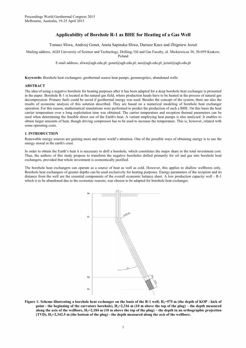
Figure 1: Scheme illustrating a borehole heat exchanger on the basis of the R-1 well; H1=575 m (the depth of KOP - kick of
point - the beginning of the curvature borehole), H2=2,316 m (10 m above the top of the plug) – the depth measured
along the axis of the wellbore, H2=2,184 m (10 m above the top of the plug) – the depth in an orthographic projection
(TVD), H3=2,342.5 m (the bottom of the plug) - the depth measured along the axis of the wellbore.
Sliwa et al.
2
2. CHARACTERISTICS OF THE OBJECT OF THE STUDY – THE R-1 WELL
The R-1 well was drilled as a directional well with a wellbore profile as in the figure below (fig. 1). The depth of to the top of the
cement plug is 2,390m (the total well depth is 2,436 m). The deviation of the botom of the borehole from the vertical axis 720.8,
and the azimuth deviation of the bottom of the wellbore is 72.9. The assumed depth of the borehole heat exchanger, measured
along the axis, is 2,316 m (2,184 m TVD – true vertical depth).
The borehole is located in a large city in Poland. The current design of the R-1 borehole is shown in the Table 1.
Table 1: Wellbore casing (conductivity of the cement slurry =1,2 Wm-1K-1).
Casing diameter Interval, m Wall thickness, mm Cementing
20`` 0 - 10 No data Cemented
13 3/8`` 0 - 306 10.90 Cemented to the surface
9 5/8`` 0 - 1889 10.03 Cemented from the bottom to 455 m
6 5/8`` 0 - 2428 10.60 Cemented from the bottom to 670 m
Detailed lithology of the R-1 well is shown in the Table 2, which also includes the thermal conductivity and volumetric heat
capacity adopted to simulate the operation of the well as a borehole heat exchanger.
Table 2: Lithology log of the R-1 well and thermal parameters of rocks.
No. Lithology Stratigraphy
Depth of
roof, m,
below
ground level
Depth of
floor, m,
below
ground level
Thickness,
m
Thermal
conductivity,
Wm-1K-1
Volumetric
heat
capacity,
MJm-3K-1
1 Rusty, gritty clays Quaternary 0 10 10 0.4 1.5
2
Clay-slates, mudstones, mica
schists with fine-grained
mica sandstone laminas
Miocene of the
Rzeszow Bay 10 510 500 1.8 2.0
3
Gray, green, brick red, olive,
and also dark gray slates with
interbeds of fine- and middle-
grained, gray sandstone with
big quartz grains
Carpathian-
Stebnica
overthrust
510 1,947 1437 2.3 2.3
4 Evaporates
Stebnica
overthrust
layer
1,947 1,959 12 4.0 1.5
5
Gray, green, brick red, olive,
and also dark gray slates
with interbeds of fine- and
middle-grained, gray
sandstone with big quartz
grains
Carpathian-
Stebnica
overthrust
1,959 1,975 16 2.3 2.3
6
Slates and sandstones– gray
slates, mica schists with fine-
grained mica sandstone
laminas and interbeds
Sarmat –
autochthonous
miocene
1,975 2,390 415 2.2 2.2
When considering the adaptation of the borehole for a borehole heat exchanger, thermal parameters are very relevant. After the
analysis of the available materials adopted were:
bottomhole temperature (at a depth of 2,340 m): 73.18C,
surface temperature: 7,0C,
the Earth's natural heat flow: 60 mWm-2,
average temperature of the drilled formation: 40.9C.
Natural variability of the formation temperature was assumed taking into account the trajectory of the axis.
3. ADAPTATION OF THE R-1 WELL FOR A BOREHOLE HEAT EXCHANGER
Adaptation is based on a partial liquidation of the wellbore through launching a plug, cutting-off the perforated interval and
supplying the wellbore with a thermally insulating column.
The designed liquidation of the R-1 well should isolate aquifers and gas-bearing horizons and prevent reservoir fluids from
migrating between horizons or escaping to the surface. The liquidation will be carried out while maintaining the existing well
design.
Sliwa et al.
3
During the adjusting works the following rules must be observed:
the sections of the casing strings, where the fastening of the mechanical plug is planned to take place should be cleaned
with a scratcher,
the sealing sections should be filled with properly selected cement slurry,
in directional wells the lengths of the overlaps must be converted into differences in depth (TVD), which cannot be less
than 15 m,
after fastening the mechanical plug wellbore must be checked for leaks,
when the slurry is bonded, the top of the cement plug must be located and checked for leaks.
The gas field completed with the R-1 well through perforation should be isolated with squeeze cementing. The length of the
overlaps amounts to from 15 m to 50 m. Additionally to ensure long-term isolation of the horizon, launching a mechanical plug is
advised.
A single and a double, made of plastic, string of the inner pipes was analyzed. These pipes will have screw threads and will be
screwed together. Running the pipes into the wellbore can be realized with a smaller rigs. Taking the mud into account (water), the
weight of the column is not more than 21 kN.
To obtain the biggest possibile area of the heat exchange it is recommended to use the centralizers for the internal column. The
centralization of the pipes was assumed in numerical calculations.
Water with a corrosion inhibitor and a viscosity reducing agent will be the heat carrier in the borehole heat exchanger. A chemical
product NOKSONN is an example of the corrosion inhibitor.
The efficiency of the borehole heat exchangers depends significantly on the inner pipes characteristics. After detailed technical and
economic analysis it was decided to use polymer materials. Thermal resistance tests as well as one and triaxial compressive
strength tests were performed in borehole-like conditions. Tensile stresses analysis of the pipes and the threaded connections of the
selected plastic pipes were also performed, including the mechanical and thermal elongation.
4. DESIGNS ANALYSED
The construction of the inner column of the borehole heat exchanger has a significant impact on the amount of pressure and
temperature losses of the heat carrier obtained in the course of its operation. It affects directly the achieved efficiency of the heating
system. Two specific variants of the design of the inner column are presented below. They were selected after the analysis of the
applicability of different pipes available in the market and as well as the analysis of different combinations of pipes of the inner
column.
Table 3: Construction of a multi-layer inner column (design No. 1).
Layer, according to
fig. 1 Material
External diameter,
dout, mm
Internal diameter,
din, mm
2 Plastic (=0.24 Wm-1K-1, c=1,700
Jkg-1·K-1, =1,150 kgm-3) 120 100
3 Water (=0.6 Wm-1K-1) 100 90
5 Plastic (=0,24 Wm-1K-1, c=1,700
Jkg-1·K-1, =1,150 kgm-3) 90 70
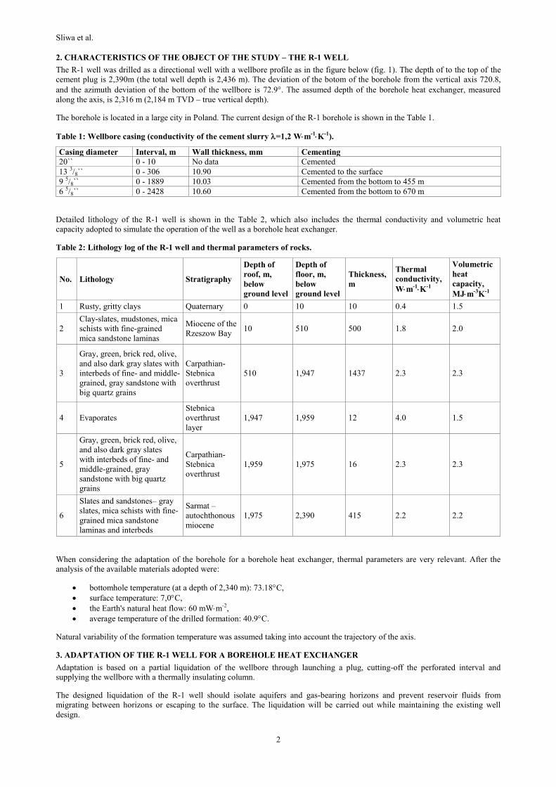
The first variant involves creating the inner column made of two plastic pipes of different diameters, the space between the tubes is
filled with water (liquid that is present in a borehole while running of the first and the second column). The details of the
construction are shown in the figure 2 and the dimensions in the Table 3. The essence of the design is so-called heat transition
resistance between different materials. The thermal resistance of such columns in the radial direction is not solely related to the
thermal conductivity of the particular materials only. It is bigger because of the penetration of heat from the first layer to the second
and from the second to the third.
Table 4: Construction of multi-layer inner column (design No. 2).
Layer, according
to fig. 1 Material
External diameter,
dout, mm
Internal diameter, din,
mm
2 Plastic (=0.24 Wm-1K-1, c=1,700
Jkg-1·K-1, =1,150 kgm-3) 120 100
3 Air (=0.026 Wm-1K-1) 100 90
5 Plastic (=0.24 Wm-1K-1, c=1,700
Jkg-1·K-1, =1,150 kgm-3) 90 70
The second design is almost the same as the first one. The only difference is that the space between the inner and the outer layer of
the insulating column is filled with gas (air, nitrogen). Air can be pumped into this space at any time after the beginning of the
operation. Furthermore, it should fill only the upper part of the inner (insulating) column because it is where the biggest
Sliwa et al.
4
temperature differences between the heat carrier flowing downward and upward occur. By adjusting the gas pressure in the inner
column the length of the insulating zone can be controlled while the pipes and well head strength limitations are maintained. We
assume that space between pipes should be filled with air over the length of 500 m. The construction of the inner (thermally
insulating) column is described in the Table 4.
Figure 2: Cross section of the borehole heat exchanger with a multi-layer internal column (insulating), 1 – rock and
cemented pipes 65/8`` 2 - the outer layer of the column, 3 – the middle layer of the column (filled with water), 4 – the
area of a liquid flow inside the inner column (insulating) – the upward flow, 5 – the inner layer of the column, 6 -the
area of a liquid flow in the annular space between the 65/8`` pipe and the inner column (insulating) – a downward
movement of the carrier.
Table 5: Pressure losses during the flow of the heat carrier through the borehole heat exchanger - for both designs.
Parameter Unit Flow rate of heat carrier, dm3min-1
50 100 150 200
Cross-sectional area of the annular space m² 0.00568
Cross-sectional area of the inner pipe m² 0.00385
The average flow velocity in the annular space ms-1 0.1467 0.2935 0.4402 0.5869
The average flow velocity in the inner pipe ms-1 0.2165 0.4331 0.6496 0.8661
The Reynolds number for the flow in the annular
space — 3,045 6,091 9,136 12,182
The Reynolds number for the flow in the inner pipe — 11,619 23,239 34,858 46,477
Linear pressure losses during the flow of fluid
through the annular space kPa 46 160 338 580
Linear pressure losses during the flow of fluid
through the inner pipe kPa 23 78 160 268
Total linear pressure losses kPa 69 238 498 848
Hydraulic power of the flow in the annular space W 38 266 845 1,934
Hydraulic power of the flow in the inner pipe W 19 130 401 892
Total hydraulic power W 57 396 1,246 2,826
Approximate power consumed by the pump motor W 96 661 2,080 4,719
Table 6: Parameters of the heat carrier.
Parameter Unit Value
Temperature oC 10
Thermal conductivity of the fluid Wm-1·K-1 0.27
Density kgm-3 999.6
Specific heat Jkg-1K-1 4,215
Kinematic viscosity m2s-1 0.0000013
Sliwa et al.
5
Table 5 displays the basic hydraulic parameters of the borehole heat exchanger with the depth of 2,316 m and the construction as
shown in the fig. 1. Pressure losses were calculated for four different flow rates of the heat carrier and for the most unfavorable
conditions, that are expected to show up by the end of the 10th year of exploitation. Parameters of the heat carrier are shown in the
Table 6.
5. MATHEMATICAL MODEL OF DEEP BHE
A computer numerical simulator BoHEx, which models borehole heat exchangers, was used to model heat transfer in a deep BHE
(Gonet et al., 2011, Sliwa et al., 2010, Jaszczur et al., 2010). In order to simplify the construction of the model as well as the
numerical solution itself, the analyzed system was considered as consisting of two separate subdivisions.
The first area was related to the processes taking place within the borehole. In this sub-area the heat carrier flow occurs, the heat
penetration into the walls, heat transfer through the walls and its transmission into the formation. The main goal here is to
determine the fluid temperature over the entire length of the channels, depending on the temperature outside the formation. In the
described model, this area will be analyzed as a non-stationary, non-linear heat source, what will allow to examine the phenomena
of unsteady absorbing heat.
The second area is associated with the formation and extends from the outer contact surface with the casing until the outer edges of
the modeled system. In case of absence of underground flow, heat transfer by conduction dominates, and thermal processes due to
the scale and mass of the system run very slowly.
Modeling in the first area reduces to solving the equation of fluid motion with the equation of heat transport. Depending on
boundary conditions used, the system of equations composed of the continuity equation, the Navier-Stokes equations for each of
the three components of velocity vector and heat transfer equations, should be solved. These equations for turbulent flow must be
supplemented by an appropriate model allowing to determine the size of the turbulence. Assuming the absence of chemical
reactions or phase transitions in the considered heat carrier, these equations take the form of a tensor notation (Gonet et al. 2011):
𝜕𝜌
𝜕𝑡+ 𝜌
𝜕𝑈𝑖
𝜕𝑥𝑖= 0 (1)
𝜕𝑈𝑖
𝜕𝑡+ 𝑈𝑗
𝜕𝑈𝑖
𝜕𝑥𝑗= −
1
𝜌
𝜕𝑃
𝜕𝑥𝑖+ 𝑣
𝜕2𝑈𝑖
𝜕𝑥𝑗𝑥𝑗 (2)
𝜕𝑇
𝜕𝑡+ 𝑈𝑖
𝜕𝑇
𝜕𝑥𝑖= 𝑎
𝜕2𝑇
𝜕𝑥𝑗𝑥𝑗 (3)
Where , t, U are respectively the density of the heat carrier, time, and speed of the heat carrier. Assuming that the flow is forced,
the heat transport equation can be solved as an independent equation.
In order to determine the heat transfer coefficient, a parameter that is crucial in the heat transfer. A number of empirical
relationships were applied, which allowed us to calculate the Nusselt number Nu for the existing flow. For a flow through a pipe
these formulas take a form as:
𝑁𝑢 = 0.021𝑅𝑒0.8𝑃𝑟𝑓0.43 (
𝑃𝑟𝑓
𝑃𝑟𝑤)
0.25 (4)
for pipes with smooth walls and Reynolds number range of Re(104-5106) and Prandtl number range of Pr(0,6-2500):
𝑁𝑢 = 0.15𝑅𝑒0.33𝑃𝑟𝑓0.43𝐺𝑟0.1 (
𝑃𝑟𝑓
𝑃𝑟𝑤)
0.25 (5)
for laminar flow, where Reynolds and Grashof (Gr) number are defined as below:
Re= 𝑈∙𝐷∙𝜌
𝜇 , 𝐺𝑟 =
𝑔𝛽𝐷3∆𝑇
𝜐2 (6)
Where subscript f denotes the value of the parameter for the average temperature of the fluid (arithmetic mean of temperature at the
inflow and the outflow of the annular and circular channel), w is the value of parameter for a pipe wall temperature.
The above formulas assume the hydrodynamic and thermal stabilization of the flow. Since the flow at the inflow to the borehole
heat exchanger and in its lower part is not stabilized L<60D or there is some curvature; this fact was taken into account during the
calculations and a higher Nusselt number in the initial section of the pipe was used. Determination of the Nusselt number value
allows us to calculate the average surface heat transfer coefficient from the formula:
ℎ̅ =𝜆𝑓̅̅̅̅
𝐷ℎ𝑁𝑢̅̅ ̅̅ (7)
where Dh oraz f denote respectively the hydraulic diameter and the thermal conductivity of the fluid.
The heat exchange in the rock is described using three-dimensional, non-stationary heat transfer equation, which in the Cartesian
coordinate system takes the form:
ρcp∂T
∂t=
∂
∂x(λx
∂T
∂x) +
∂
∂y(λy
∂T
∂y) +
∂
∂z(λz
∂T
∂z) + s (8)
Sliwa et al.
6
Where ρ, cp, λ represent thermophysical properties - density, specific heat and thermal conductivity - in a given layer (area) of the
rock mass. These values may change in the formation continuously and discretely. Source element s allows taking into account the
parameters such as natural temperature gradient, and parameters not taken into account in the heat exploitation forecast, like phase
transitions or filtration in different layers of the rock mass.
The above presented system of equations representing the mathematical model of the issue together with the initial and the
boundary conditions (described by Gonet et al. 2011) must be solved for each point of the medium. Analytical solution of the above
equations is not known in the literature, therefore, numerical methods were used to resolve them.
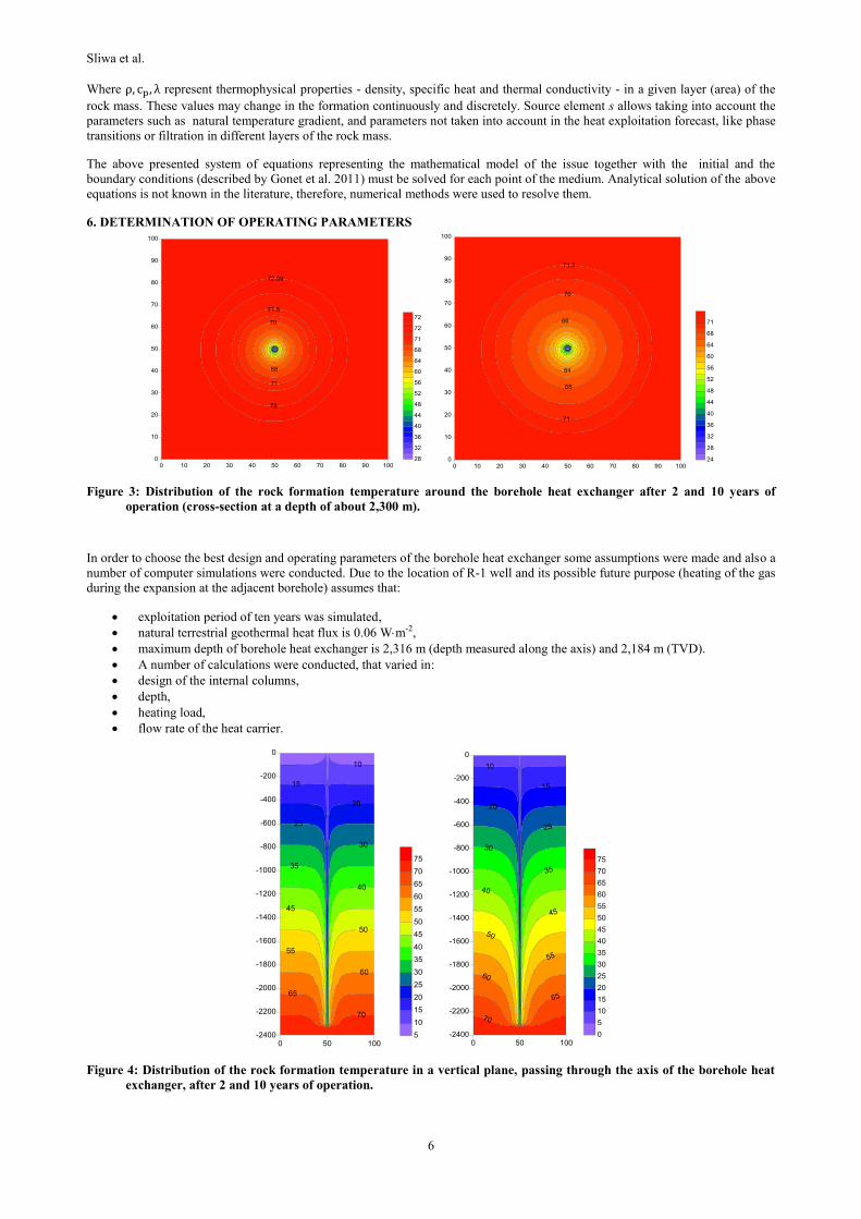
6. DETERMINATION OF OPERATING PARAMETERS
Figure 3: Distribution of the rock formation temperature around the borehole heat exchanger after 2 and 10 years of
operation (cross-section at a depth of about 2,300 m).
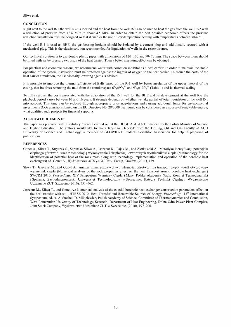
In order to choose the best design and operating parameters of the borehole heat exchanger some assumptions were made and also a
number of computer simulations were conducted. Due to the location of R-1 well and its possible future purpose (heating of the gas
during the expansion at the adjacent borehole) assumes that:
exploitation period of ten years was simulated,
natural terrestrial geothermal heat flux is 0.06 Wm-2,
maximum depth of borehole heat exchanger is 2,316 m (depth measured along the axis) and 2,184 m (TVD).
A number of calculations were conducted, that varied in:
design of the internal columns,
depth,
heating load,
flow rate of the heat carrier.
Figure 4: Distribution of the rock formation temperature in a vertical plane, passing through the axis of the borehole heat
exchanger, after 2 and 10 years of operation.
Sliwa et al.
7
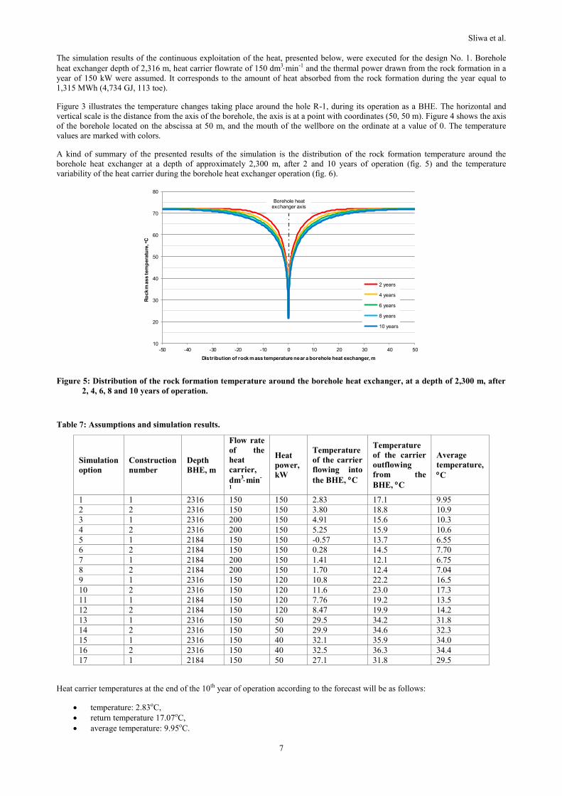
The simulation results of the continuous exploitation of the heat, presented below, were executed for the design No. 1. Borehole
heat exchanger depth of 2,316 m, heat carrier flowrate of 150 dm3min-1 and the thermal power drawn from the rock formation in a
year of 150 kW were assumed. It corresponds to the amount of heat absorbed from the rock formation during the year equal to
1,315 MWh (4,734 GJ, 113 toe).
Figure 3 illustrates the temperature changes taking place around the hole R-1, during its operation as a BHE. The horizontal and
vertical scale is the distance from the axis of the borehole, the axis is at a point with coordinates (50, 50 m). Figure 4 shows the axis
of the borehole located on the abscissa at 50 m, and the mouth of the wellbore on the ordinate at a value of 0. The temperature
values are marked with colors.
A kind of summary of the presented results of the simulation is the distribution of the rock formation temperature around the
borehole heat exchanger at a depth of approximately 2,300 m, after 2 and 10 years of operation (fig. 5) and the temperature
variability of the heat carrier during the borehole heat exchanger operation (fig. 6).
Figure 5: Distribution of the rock formation temperature around the borehole heat exchanger, at a depth of 2,300 m, after
2, 4, 6, 8 and 10 years of operation.
Table 7: Assumptions and simulation results.
Simulation
option
Construction
number
Depth
BHE, m
Flow rate
of the
heat
carrier,
dm3min-
1
Heat
power,
kW
Temperature
of the carrier
flowing into
the BHE, C
Temperature
of the carrier
outflowing
from the
BHE, C
Average
temperature,
C
1 1 2316 150 150 2.83 17.1 9.95
2 2 2316 150 150 3.80 18.8 10.9
3 1 2316 200 150 4.91 15.6 10.3
4 2 2316 200 150 5.25 15.9 10.6
5 1 2184 150 150 -0.57 13.7 6.55
6 2 2184 150 150 0.28 14.5 7.70
7 1 2184 200 150 1.41 12.1 6.75
8 2 2184 200 150 1.70 12.4 7.04
9 1 2316 150 120 10.8 22.2 16.5
10 2 2316 150 120 11.6 23.0 17.3
11 1 2184 150 120 7.76 19.2 13.5
12 2 2184 150 120 8.47 19.9 14.2
13 1 2316 150 50 29.5 34.2 31.8
14 2 2316 150 50 29.9 34.6 32.3
15 1 2316 150 40 32.1 35.9 34.0
16 2 2316 150 40 32.5 36.3 34.4
17 1 2184 150 50 27.1 31.8 29.5
Heat carrier temperatures at the end of the 10th year of operation according to the forecast will be as follows:
temperature: 2.83oC,
return temperature 17.07oC,
average temperature: 9.95oC.
10
20
30
40
50
60
70
80
-50 -40 -30 -20 -10 0 10 20 30 40 50
Ro
ck
mass tem
pera
ture
, oC
Distribution of rock mass temperature near a borehole heat exchanger, m
2 years
4 years
6 years
8 years
10 years
Borehole heat exchanger axis

Sliwa et al.
8
The results of other operation simulations are shown in Table 7.
Figure 6: Temperature variability of the heat carrier during operation of the borehole heat exchanger; 1 - exit temperature
of BHE, 2 - medium temperature, 3 - inlet temperature to BHE.
In options from 13 to 17 the temperature of the heat carrier flowing into the annular space with the heat power of 50 and 40 kW is
higher than the temperature of subsurface rocks. Temperature distribution around the BHE for variant 13 is shown in figure 7. In
such situation, there shall be a transfer of heat into the formation and further lowering of the heat carrier temperature. The
temperature distribution shows clearly that after 10 years of operation for variants 13-17 only at a depth of 800-1,000 m the heat
carrier stops cooling down and heating begins. Therefore it is recommended to make use of the existing cementing and well design.
Pipes 65/8`` and 95/8`` are cemented with overlapping. So there is the possibility of introducing an insulator in the tubular annulus in
order to reduce the heat loss. Gas (air, nitrogen) or polymer foam can serve as insulators.
Figure 7: Distribution of the rock formation temperature around the borehole heat exchange when the heat carrier
temperature flowing into the BHE is higher than rock formation temperature.
7. POSSIBILITIES OF USING THE HEAT
Gas well was regarded as a most probable heat recipient. The heat from the BHE made R-1 can be used in the process of expansion
of the gas produced from the R-1 well. Well heads of the two wellbores are approximately 20 m apart. For technical and economic
analysis of the use of the rock formation as a heat source for the technology processes in a gas well, the following options were
considered (Figure 8):
1) the main source of process heat is the rock formation and heat is transferred to the recipient in passive mode (without the
use of heat pumps),
2) the main source of heat is the rock formation, but 10 kW is delivered to the receiver (domestic hot water - DHW) with the
heat pump, the remaining energy is heating pressure reduction system in a passive mode,

Sliwa et al.
9
3) the rock formation is the main heat source and it is transmitted with the heat pump with a capacity of 150 kW.
For the economic evaluation of the investment in each case a heat plant with comparable power is an alternative heat source.
The cost of investments associated with the heat pump and installation were estimated based on available market offer and catalog
prices. The investment costs taken into account:
the cost of the project,
the cost of equipment: heat pump, buffer tank, storage tank,
the estimated cost of connecting the heat pump with the pressure reduction system,
the estimated cost of the direct connecting of the installation to the rock formation,
the cost of purchasing the pipes,
the cost of preparing the pipes (threading),
transportation of pipes,
the cost of the well head,
the cost of running the pipes,
the cost of the corrosion inhibitor,
the difference in the cost of the total and partial liquidation of the wellbore was also taken into account.
(a) (b) ( c)
Figure 8: Three variants of BHE operation for the needs of the gas well.
The heat pump is switched on to work if the flow temperature falls below the assumed 30 degrees (with a hysteresis of 2-3°C). The
heat pump works for heating of a municipal water using a water returning into the formation after transmitting the heat to the gas
pressure reduction system.
Due to the temperature range of the application of the heat pump maximum heat pump inflow temperature cannot exceed 20°C,
optimally not more than 15°C, it requires the use of a mixing valve.
The selected buffer tank allows the direct connection of additional heat sources – alternative gas boiler and electric heater. The
possibility of using heat pumps with capacities of 40, 50, 120 and 150 kW was also analysed. A full load of 150 kW throughout the
year (SPF = 100%) at COP = 3.0 was assumed. In case of hot water production or low-temperature heating, the desired temperature
of 45°C was assumed, the heat carrier outflowing from the condenser must have a temperature of 48°C. Additionally the cooling of
the heat carrier outflowing from evaporator to 4°C, was assumed.
The use of low temperature heat for gas expansion technology requires an individual approach. It is recommended to apply cascade
expansion, to utilize the heat at temperatures above 30°C.
Sliwa et al.
10
CONCLUSION
Right next to the wel R-1 the well R-2 is located and the heat from the well R-1 can be used to heat the gas from the well R-2 with
a reduction of pressure from 13.6 MPa to about 4.5 MPa. In order to obtain the best possible economic effects the pressure
reduction installation must be designed so that it enables the use of low-temperature heating with temperatures between 30-40oC.
If the well R-1 is used as BHE, the gas-bearing horizon should be isolated by a cement plug and additionally secured with a
mechanical plug. This is the classic solution recommended for liquidation of wells in the reservoir area.
Our technical solution is to use double plastic pipes with dimensions of 120100 and 9070 mm. The space between them should
be filled with air by pressure extrusion of the heat carrier. Then a better insulating effect can be obtained.
For practical and economic reasons, we recommend water with corrosion inhibitor as a heat carrier. In order to maintain the stable
operation of the system installation must be protected against the ingress of oxygen to the heat carrier. To reduce the costs of the
heat carrier circulation, the use viscosity lowering agents is advised.
It is possible to improve the thermal efficiency of BHE based on the R-1 well by better insulation of the upper interval of the
casing, that involves removing the mud from the annular space 65/895/8`` and 95/8133/8`` (Table 1) and its thermal sealing.
To fully recover the costs associated with the adaptation of the R-1 well for the BHE and its development at the well R-2 the
playback period varies between 10 and 16 years. It strongly depends on whether we take partial of total liquidation of the well R-1
into account. This time can be reduced through appropriate price negotiations and raising additional funds for environmental
investments (CO2 emissions, based on the EU Directive No. 28/2009 heat pump can be considered as a source of renewable energy,
what qualifies such projects for financial support).
ACKNOWLEDGEMENTS
The paper was prepared within statutory research carried out at the DOGF AGH-UST, financed by the Polish Ministry of Science
and Higher Education. The authors would like to thank Krystian Klepczyk from the Drilling, Oil and Gas Faculty at AGH
University of Science and Technology, a member of GEOWIERT Students Scientific Association for help in preparing of
publications.
REFERENCES
Gonet A., Sliwa T., Stryczek S., Sapinska-Sliwa A., Jaszczur K., Pająk M., and Złotkowski A.: Metodyka identyfikacji potencjału
cieplnego górotworu wraz z technologią wykonywania i eksploatacji otworowych wymienników ciepła (Methodology for the
identification of potential heat of the rock mass along with technology implementation and operation of the borehole heat
exchangers) ed. Gonet A., Wydawnictwa AGH (AGH Univ. Press), Kraków, (2011), 439.
Sliwa T., Jaszczur M., and Gonet A.: Analiza numeryczna wpływu własności górotworu na transport ciepła wokół otworowego
wymiennik ciepła (Numerical analysis of the rock properties effect on the heat transport around borehole heat exchanger)
SWCIM 2010, Proceedings, XIV Sympozjum Wymiany Ciepła i Masy, Polska Akademia Nauk, Komitet Termodynamiki
i Spalania, Zachodniopomorski Uniwersytet Technologiczny w Szczecinie, Katedra Techniki Cieplnej, Wydawnictwo
Uczelniane ZUT, Szczecin, (2010), 551–562.
Jaszczur M., Sliwa T., and Gonet A.: Numerical analysis of the coaxial borehole heat exchanger construction parameters effect on
the heat transfer with soil, HTRSE 2010, Heat Transfer and Renewable Sources of Energy, Proceedings, 13th International
Symposium, ed. A. A. Stachel, D. Mikielewicz, Polish Academy of Science, Committee of Thermodynamics and Combustion,
West Pomeranian University of Technology, Szczecin, Department of Heat Engineering, Dolna Odra Power Plant Complex,
Joint Stock Company, Wydawnictwo Uczelniane ZUT w Szczecinie, (2010), 197–206.


