
NASA CR 120873
APPLICATIONSTECHNOLOGY SATELLITE
ADVANCED MISSIONS STUDY
FINAL REPORT
VOLUME I OF II
CASE FILECOPY
SPACE & ELECTRONICS DIVISION
prepared for
NATIONAL AERONAUTICS AND SPACE ADMINISTRATION
NASA Lewis Research Center
Contract NAS 3-14360
NASA CR 120873
APPLICATIONSTECHNOLOGY SATELLITE
ADVANCED MISSIONS STUDY
FINAL REPORT
VOLUME I OF II
SPACE & ELECTRONICS DIVISION
prepared for
NATIONAL AERONAUTICS AND SPACE ADMINISTRATION
NASA Lewis Research Center
Contract NAS 3-14360
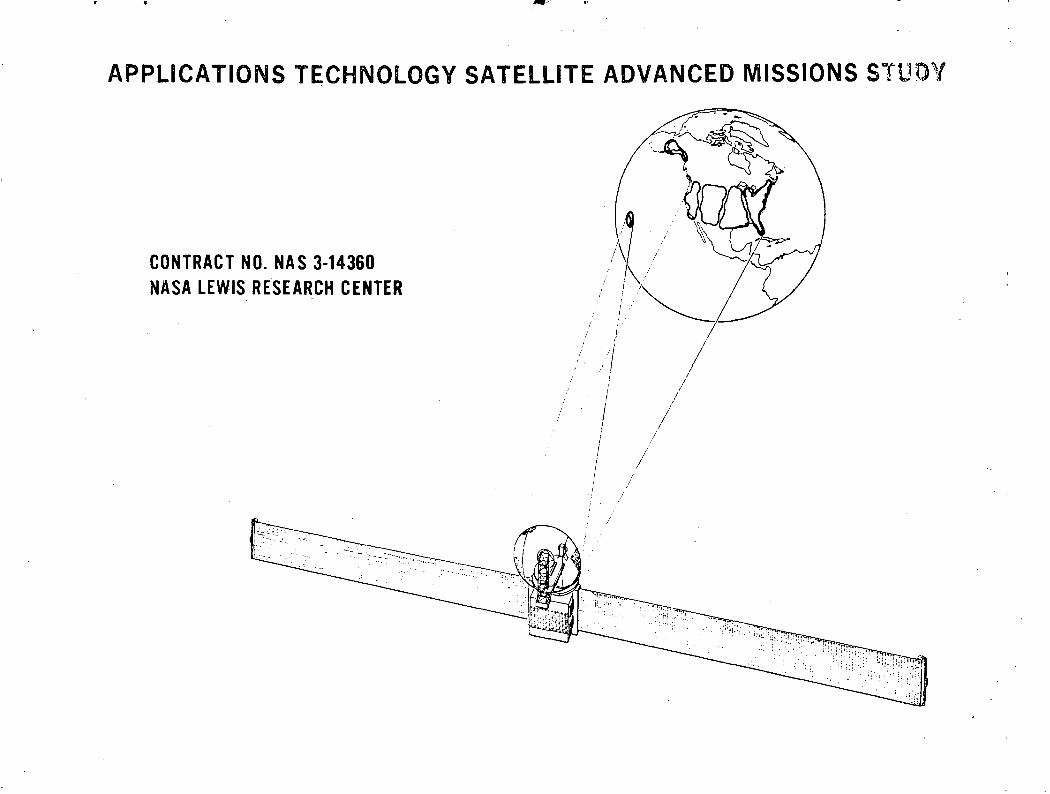
APPLICATIONS TECHNOLOGY SATELLITE ADVANCED MISSIONS STUDY
CONTRACT NO. NAS 3-14360NASA LEWIS RESEARCH CENTER
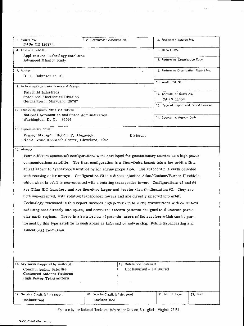
1. Report No.
NASA CR 120873
2. Government Accession No.
4. Title and Subtitle
Applications Technology SatellitesAdvanced Mission Study
7. Author(s)
D. L. Robinson et. al.
9. Performing Organization Name and Address
Fairchild IndustriesSpace and Electronics DivisionGermantown, Maryland 20767
12. Sponsoring Agency Name and Address
National Aeronautics and Space AdministrationWashington, D. C. 20546
3. Recipient's Catalog No.
5. Report Date
6. Performing Organization Code
8. Performing Organization Report No.
10. Work Unit No.
11. Contract or Grant No.
NAS 3-14360
13. Type of Report and Period Covered
14. Sponsoring Agency Code
15. Supplementary Notes
Project Manager, Robert E. Alexovich,NASA Lewis Research Center, Cleveland, Ohio
Division,
16. Abstract
Four different spacecraft configurations were developed for geostationary service as a high power
communications satellite. The first configuration is a Thor-Delta launch into a low orbit with a
spiral ascent to synchronous altitude by ion engine propulsion. The spacecraft is earth oriented
with rotating solar arrays. Configuration #2 is a direct injection Atlas/Centaur/Burner n vehicle
which when in orbit is sun-oriented with a rotating transponder tower. Configurations #3 and #4
are Titan ETC launches, and are therefore larger and heavier than Configuration #2. They are
both sun-oriented, with rotating transponder towers and are directly injected into orbit.
Technology discussed in this report includes high power (up to 2 kW) transmitters with collectors
radiating heat directly into space, and contoured antenna patterns designed to illuminate partic-
ular earth regions. There is also a review of potential users of the services which can be per-
formed by this type satellite in such areas as information networking, Public Broadcasting and
Educational Television.
17. Key Words (Suggested by Author(s))
Communication SatelliteContoured Antenna PatternsHigh Power Transmitters
19. Security Classif. (of this report)
Unclassified
18. Distribution Statement
Unclassified - Unlimited
20. Security Classif. (of this page) 21. No. of Pages 22. Price*
Unclassified
' For sale by the National Technical Information Service, Springfield. Virginia 22151
NASA-C-lnS (Rev. 6-71)

TABLE OF CONTENTS
Section Subject Page
Summary
1 Introduction 1-1
1.1 Mission Objectives 1-1
1.2 Study Objectives 1-1
1.3 Constraints 1-2
1.4 Reactor-Thermoelectric Power Systems 1-7
2 High Power Communication Satellite Missions 2-1
2.1 Missions and Requirements 2-1
2.2 Baseline Information Networking Experiments 2-3
3 Ascent Trajectories and Launch Sequences 3-1
3.1 Titan IHC Trajectory and Launch Sequence 3-1
3.2 Atlas/Centaur/Burner II Trajectory andLaunch Sequences 3-10
3. 3 Delta/Ion Engine Launch and Injection Sequences 3-18
4 Spacecraft Description 4-1
4.1 Summary of Spacecraft Characteristics 4-1
4.2 Spacecraft Configuration 4-16
4. 3 Antennas and Feeds 4-35
4.4 Communications Transponder Subsystem 4-52
4.5 Power Supply Subsystem 4-66
4. 6 Attitude Control Subsystem 4-90
4.7 Orbit Control Subsystem 4-118
4.8 Thermal Control Subsystem 4-122
4. 9 Telemetry and Command Subsystem 4-133

TABLE OF CONTENTS (Cont'd.)
Section Subject Page
4.10 Structures 4-138
5 Tradeoffs and Analysis 5-1
5.1 Spacecraft - Ground Station 5-1
5. 2 Spacecraft System and Subsystem InterrelationTradeoffs 5-24
5.3 Antenna and Feeds 5-29
5.4 Communications Subsystem Analysis and Tradeoffs 5-97
5.5 Power Supply Subsystem 5-107
5.6 Attitude Control 5-121
5.7 Orbit Control 5-143
5.8 Thermal Control Analysis 5-145
5. 9 Telemetry and Command System Tradeoffs 5-161
5.10 Structural Analysis 5-162
6 Critical Research and Development 6-1
6.1 Spacecraft Technology Critical R & D 6-1
6. 2 Earth Terminal Technology Critical R & D 6-5
6. 3 Communication System Technology Required R & D 6-5
6.4 Recommended Future Studies 6-9
7 Additional Experiments 7-1/7-2
7.1 Operational Experiments 7-1/7-2
7.2 Technology Experiments 7-25
8 Manufacturing, Testing and Support 8-1
8.1 Manufacturing and Assembly 8-1
8.2 Testing and Support 8-2
11

TABLE OF CONTENTS (Cont'd.)
Subject Page
Ground Support System 9-1
9.1 Earth Terminals 9-1
9.2 Spacecraft Performance Evaluation 9-9
10 Launch Through Orbit Injection 10-1
10.1 Ground Support Equipment 10-1
10.2 Launch Site Support 10-1
11 Implementation Schedule and Requirements 11-1
11.1 Work Breakdown Structure (WBS) 11-1
11.2 Gross Resources Required 11-1
11. 3 Implementation Schedule 11-1
12 Conclusions and Recommendations 12-1
12.1 Small Terminal Information Networking Systems 12-1
12.2 Demonstration of High Power Satcom Technology 12-2
12. 3 Assessment of Technical Feasibility 12-2
12.4 Selection of Spacecraft Approach 12-3
12.5 Recommended Additional Experiments 12-4
12. 6 Recommended Research and Development 12-4
12.7 Recommended Future Studies 12-5
iii
LIST OF ILLUSTRATIONS
Figure Title Page
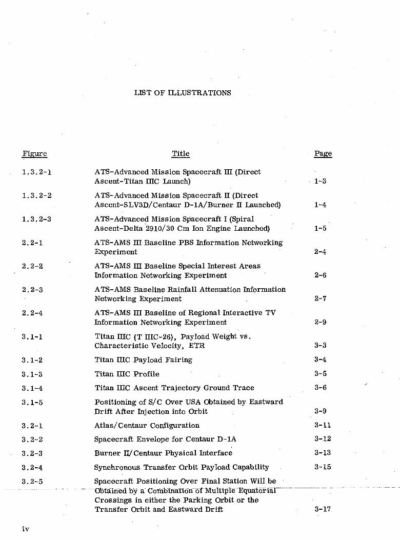
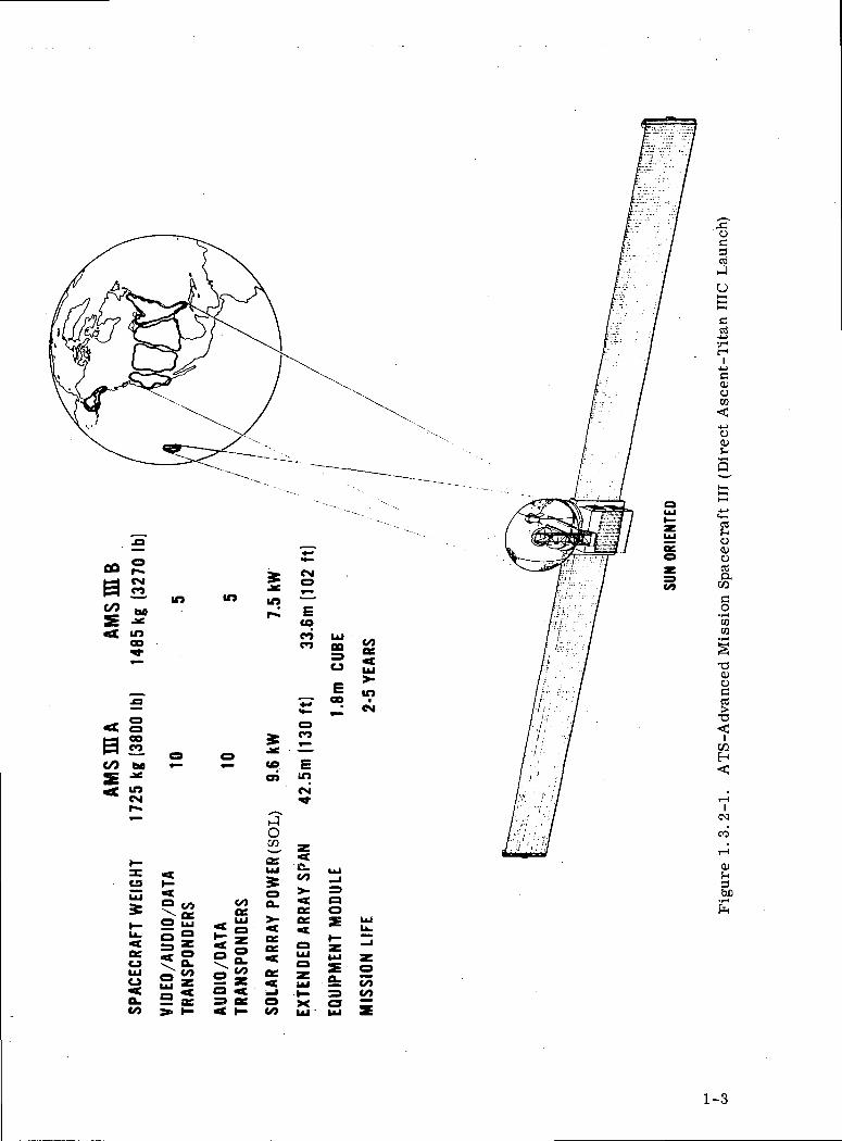
1.3.2-1 ATS-Advanced Mission Spacecraft m (DirectAscent-Titan me Launch) 1-3
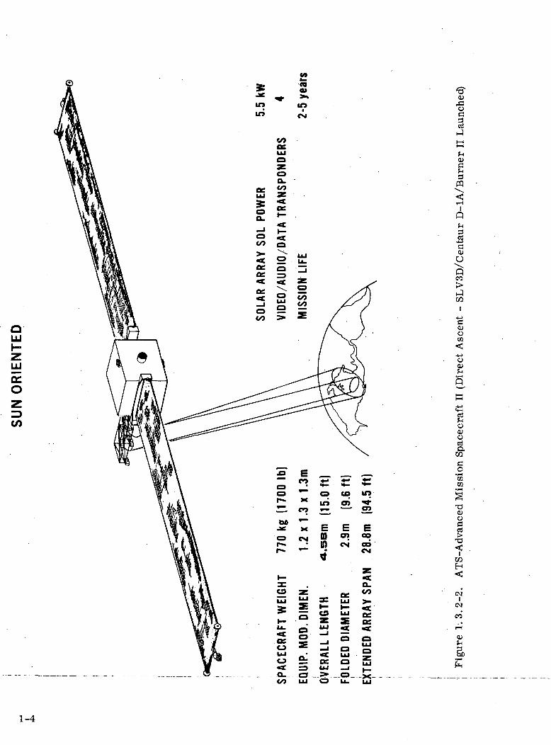
1.3.2-2 ATS-Advanced Mission Spacecraft n (DirectAscent-SLVSD/Centaur D-lA/Burner n Launched) 1-4
1.3.2-3 ATS-Advanced Mission Spacecraft I (SpiralAscent-Delta 2910/30 Cm Ion Engine Launched) 1-5
2.2-1 ATS-AMS HI Baseline PBS Information NetworkingExperiment 2-4
2.2-2 ' ATS-AMS m Baseline Special Interest AreasInformation Networking Experiment 2-6
2.2-3 ATS-AMS Baseline Rainfall Attenuation InformationNetworking Experiment . 2-7
2.2-4 ATS-AMS HI Baseline of Regional Interactive TVInformation Networking Experiment 2-9
3.1-1 Titan me (T HIC-26), Pay load Weight vs.Characteristic Velocity, ETR 3-3
3.1-2 Titan IHC Payload Fairing 3-4
3.1-3 Titan HIC Profile . 3-5
3.1-4 Titan EEC Ascent Trajectory Ground Trace 3-6
3.1-5 Positioning of S/C Over USA Obtained by EastwardDrift After Injection into Orbit 3-9
3.2-1 Atlas/Centaur Configuration 3-11
3.2-2 Spacecraft Envelope for Centaur D-1A 3-12
3.2-3 Burner D/Centaur Physical Interface 3-13
3.2-4 Synchronous Transfer Orbit Payload Capability 3-15
3.2-5 Spacecraft Positioning Over Final Station Will beObtained by a"CombinatioiTof Multiple^ "Equatorial ~Crossings in either the Parking Orbit or theTransfer Orbit and Eastward Drift 3-17
iv

LIST OF ILLUSTRATIONS (Cont'd.)
Figure Title Page
3.3-1 Delta Outboard Profile 3-20
3.3-2 Pay load Envelope, Two Stage, 5414 Attach Fitting 3-21
3.3-3 5414 Conical Attach Fitting Detailed Dimensions 3-22
3.3-4 Delta 2910 Capabilities 3-23
3.3-5 Delta 2910 Load vs. Altitude 3-24
3.3-6 During the Final Stage of the Spiral Ascent, theNecessary Adjustment to Obtain Final OrbitPosition will be made 3-29
3.3-7 Typical Orbit Radius vs. Time 3-30
3.3-8 Typical Thrust Profile 3-32
4.2-1 ATS-AMS niA Sun Oriented Spacecraft 25 ft.Fairing Titan Booster 4-17/4-18
4.2-2 Equipment Module Structure ATS-AMS HI 4-21/4-22
4.2-3 ATS-AMS HIA Sun Oriented Spacecraft EquipmentLayout 4-25/4-26
4.2-4 Layout of ATS-AMS H 4-29/4-30
4.2-5 Earth Oriented Spacecraft Rotating Arrays DeltaBooster 2910 4-33/4-34
4.3.1-1 ATS-AMS HLA Multibeam Contoured Coverage forPBS Experiment 4-36
4.3.1-2 ATS-AMS El Alaska Coverage from Two SatelliteLocations 4-37
4.3.1-3 ATS-AMS IE Multibeam Contoured Coverage forITV Experiment 4-39
4.3.1-4 ATS-AMS IE Antennas 4-40
4.3.1-5 ATS-AMS El Conceptual Feed Layout 4-43
4.3.2-1 Small Antenna Dimensions 4-47
4.3.2-2 Large Antenna Dimensions 4-50
4.4.1.3-1 Typical Frequency Plan (ATS-AMS EIA) 4-53
LIST OF ILLUSTRATIONS (Cont'd.)
Figure Title Page
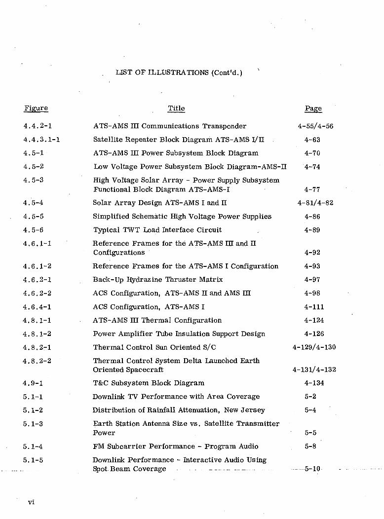
4.4.2-1 ATS-AMS m Communications Transponder 4-55/4-56
4.4.3.1-1 Satellite Repeater Block Diagram ATS-AMS 1/H 4-63
4.5-1 ATS-AMS IE Power Subsystem Block Diagram 4-70
4.5-2 Low Voltage Power Subsystem Block Diagram-AMS-n 4-74
4.5-3 High Voltage Solar Array - Power Supply SubsystemFunctional Block Diagram ATS-AMS-I 4-77
4.5-4 Solar Array Design ATS-AMS I and II 4-81/4-82
4.5-5 Simplified Schematic High Voltage Power Supplies 4-86
4.5-6 Typical TWT Load Interface Circuit , 4-89
4.6.1-1 Reference Frames for the ATS-AMS m and nConfigurations 4-92
4.6.1-2 Reference Frames for the ATS-AMS I Configuration 4-93
4.6.2-1 Back-Up Hydrazine Thruster Matrix 4-97
4.6.2-2 ACS Configuration, ATS-AMS H and AMS HI 4-98
4.6.4-1 ACS Configuration, ATS-AMS I 4-111
4.8.1-1 ATS-AMS HI Thermal Configuration 4-124
4.8.1-2 Power Amplifier Tube Insulation Support Design 4-126
4.8.2-1 Thermal Control Sun Oriented S/C 4-129/4-130
4.8.2-2 Thermal Control System Delta Launched EarthOriented Spacecraft 4-131/4-132
4.9-1 T&C Subsystem Block Diagram 4-134
5.1-1 Downlink TV Performance with Area Coverage 5-2
5.1-2 Distribution of Rainfall Attenuation, New Jersey 5-4
5.1-3 Earth Station Antenna Size vs. Satellite TransmitterPower 5-5
5.1-4 FM Subcarrier Performance - Program Audio 5-8
5.1-5 Downlink Performance - Interactive Audio UsingSpot Beam Coverage - 5-10
VI
LIST OF ILLUSTRATIONS (Cont'd.)
Figure Title Page
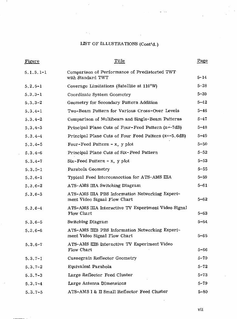
5.1.3.1-1 Comparison of Performance of Predistorted TWTwith Standard TWT 5-14
5.2.5-1 Coverage Limitations (Satellite at 110°W) 5-28
5.3.3-1 Coordinate System Geometry 5-39
5.3.3-2 Geometry for Secondary Pattern Addition 5-42
5.3.4-1 Two-Beam Pattern for Various Cross-Over Levels 5-46
5.3.4-2 Comparison of Multibeam and Single-Beam Patterns 5-47
5.3.4-3 Principal Plane Cuts of Four-Feed Pattern (x=-7dB) 5-48
5.3.4-4 Principal Plane Cuts of Four Feed Pattern (x=-5.6dB) 5-49
5.3.4-5 Four-Feed Pattern - x, y plot 5-50
5.3.4-6 Principal Plane Cuts of Six-Feed Pattern 5-52
5.3.4-7 Six-Feed Pattern - x, y plot 5-53
5.3.5-1 Parabola Geometry 5-55
5.3.6-1 Typical Feed Interconnection for ATS-AMS mA 5-59
5.3.6-2 ATS-AMS DIA Switching Diagram 5-61
5.3.6-3 ATS-AMS mA PBS Information Networking Experi-ment Video Signal Flow Chart 5-62
5.3.6-4 ATS-AMS IHA Interactive TV Experiment Video SignalFlow Chart 5-63
5.3.6-5 Switching Diagram 5-64
5.3.6-6 ATS-AMS HCB PBS Information Networking Experi-ment Video Signal Flow Chart 5-65
5.3.6-7 ATS-AMS DIB Interactive TV Experiment VideoFlow Chart 5-66
5.3.7-1 Cassegrain Reflector Geometry 5-70
5.3.7-2 Equivalent Parabola 5-72
5.3.7-3 Large Reflector Feed Cluster 5-73
5.3.7-4 Large Antenna Dimensions 5-79
5.3.7-5 ATS-AMS I & H Small Reflector Feed Cluster 5-80
vii

LIST OF ILLUSTRATIONS (Cont'd.)
Figure Title
5.3.7-6 Small Antenna Dimensions 5-83
5.3.8-1 Small Reflector Beam Forming Matrix 5-85
5.3.8-2 Spot Beam Switching Matrix 5-87
5.3.8-3 . Solid State Switches Matrix Configuration 5-90
5.3.8-4 Alternate Transponder Front End 5-91
5.3.8-5 Beam Assignment 5-95
5.3.8-6 Channel Routing 5-95
5.4.3-1 Simplified Transmitter/Receiver Isolation Network 5-102
5.4.3-2 Waveguide Strip Isolation & Loss vs. Cut-OffFrequency 5-105
5.4.3-3 Waveguide Strip Insertion Loss vs. Cut OffFrequency (for 100 dB Isolation) 5-106
5.5.1-1 ATS-AMS DIB Daily Power Budget DistributionDuring Equinox (EOL) 5-108
5.6.1-1 Polaris Yaw Sensing in Equatorial Orbit 5-124
5.6.2.1-1 Spacecraft Configuration at 0° and 180° 5-126
5.6.2.1-2 Spacecraft Configuration at 90° Point in Orbit 5-127
5.6.2.1-3 Spacecraft Configuration at 270° Point in Orbit 5-128
5.6.2.1-4 Solar Torques and Resulting Momentum Requirements 5-129
5.6.2.1-5 Solar Torques and Resulting Momentum Requirements 5-130
5.6.2.2-1 Gravity Gradient Torque and Resulting MomentumRequirements 5-132
5.6.2.2-2 Geometry for Gravity Gradient Torques 5-133
5.6.2.2-3 Euler Angles 5-134
5.6.2.3-1 Momentum Storage Requirements 5-140
5.6.2.3-2 Momentum Storage Requirements 5-141
5.8.1.3-1 Louver Control Characteristics 5-148
vui
LIST OF ILLUSTRATIONS (Cont'd.)
jFigure Title
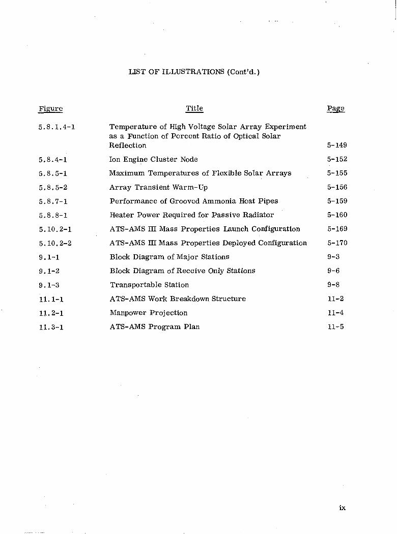
5.8.1.4-1 Temperature of High Voltage Solar Array Experimentas a Function of Percent Ratio of Optical SolarReflection 5-149
5.8.4-1 Ion Engine Cluster Node 5-152
5.8.5-1 Maximum Temperatures of Flexible Solar Arrays 5-155
5.8.5-2 Array Transient Warm-Up 5-156
5.8.7-1 Performance of Grooved Ammonia Heat Pipes 5-159
5.8.8-1 Heater Power Required for Passive Radiator 5-160
5.10.2-1 ATS-AMS m Mass Properties Launch Configuration 5-169
5.10.2-2 ATS-AMS m Mass Properties Deployed Configuration 5-170
9.1-1 Block Diagram of Major Stations 9-3
9.1-2 Block Diagram of Receive Only Stations 9-6
9.1-3 Transportable Station 9-8
11.1-1 ATS-AMS Work Breakdown Structure 11-2
11.2-1 Manpower Projection 11-4
11.3-1 ATS-AMS Program Plan 11-5
IX
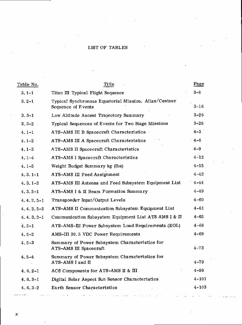
LIST OF TABLES
Table No. Title Page
3.1-1 Titan HI Typical Flight Sequence 3-8
3. 2-1 Typical Synchronous Equatorial Mission, Atlas/CentaurSequence of Events 3-16
3.3-1 Low Altitude Ascent Trajectory Summary 3-26
3. 3-2 Typical Sequences of Events for Two Stage Missions 3-28
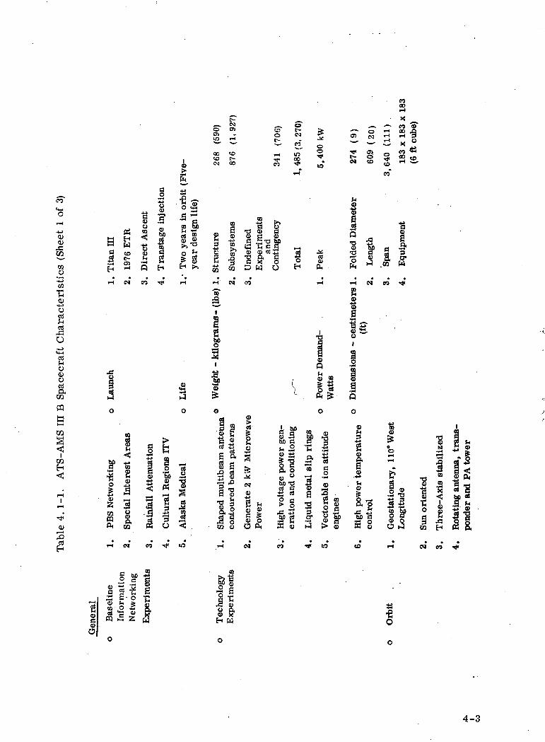
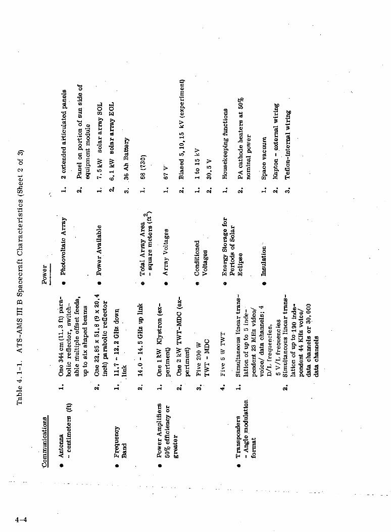
4.1-1 ATS-AMS in B Spacecraft Characteristics 4-3
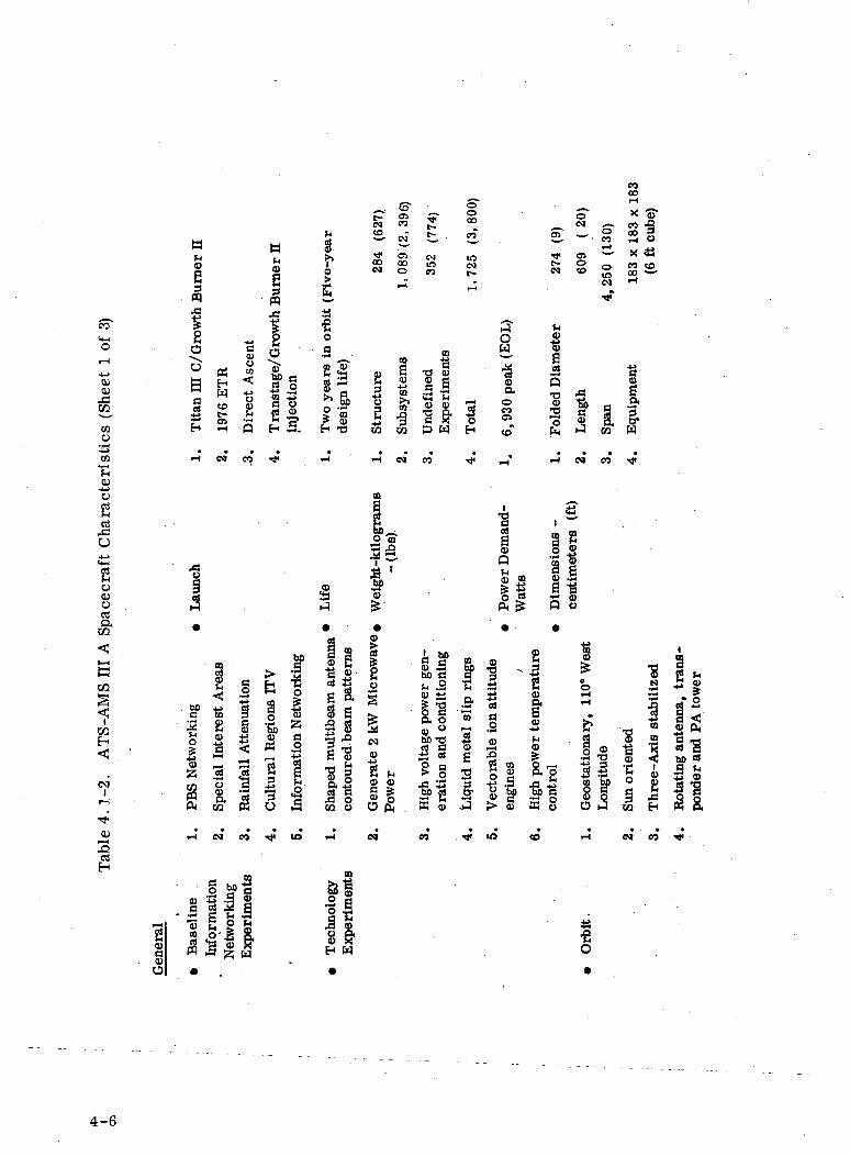
4.1-2 ATS-AMS IH A Spacecraft Characteristics ' 4-6
4.1-3 ATS-AMS II Spacecraft Characteristics 4-9
4.1-4 ATS-AMS I Spacecraft Characteristics 4-12
4.1-5 Weight Budget Summary kg (Ibs) 4-15
4.3.1-1 ATS-AMS IE Feed Assignment 4-42
4. 3.1-2 ATS-AMS III Antenna and Feed Subsystem Equipment List 4-44
4. 3.2-1 ATS-AMS I & H Beam Formation Summary 4-49
4.4. 2. 5-1 Transponder Input/Output Levels 4-60
4.4. 2. 5-2 ATS-AMS II Communication Subsystem Equipment List 4-61
4. 4. 3. 2-1 Communication Subsystem Equipment List ATS AMS I & H 4-65
4. 5-1 ATS-AMS-m Power Subsystem Load Requirements (EOL) 4-68
4.5-2 AMS-III 30.5 VDC Power Requirements 4-69
4. 5-3 Summary of Power Subsystem Characteristics forATS-AMS HI Spacecraft 4-73
4. 5-4 Summary of Power Subsystem Characteristics forATS-AMS I and H 4-79
4. 6.2-1 ACS Components for ATS-AMS H & HI 4-99
4. 6.3-1 Digital Solar Aspect Sun Sensor Characteristics 4-101
4.6.3-2 Earth Sensor Characteristics . 4-103
x

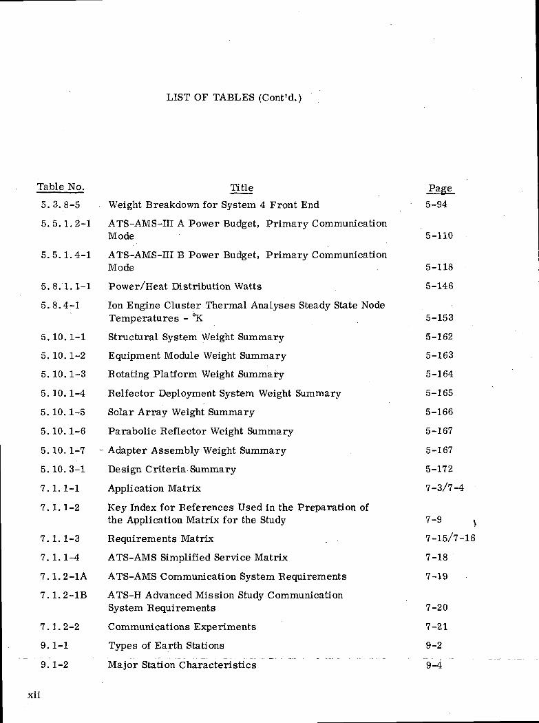
LIST OF TABLES (Cont'd.)
Table No. Title Pai
4.6.3-3 Polaris Sensor Characteristics 4-105
4. 6.3-4 Attitude Control Computer 4-106
4.6.4-1 Attitude Control Eequirements - Configuration 1 4-109
4. 6.4-2 ACS Components for ATS-AMS I 4-117
4.7.2-1 Weight and Power Summary for ATS-AMS II and HI 4-119
4.7.4-1 Orbit Control Weight and Power Summary for ATS-AMS I 4-120
4.8-1 Thermal Control Weight Estimates 4-123
4.9-1 T&C Message Characteristics 4-135
4.9.3-1 T&C Subsystem Equipment List 4-137
5.1.4-1 Uplink Performance - Video (14 GHz) 5-16
5.1.4-2 Uplink Performance of Transportable Station Video (14 GHz) 5-18
5.1.5-1 Combined Uplink and Downlink Performance - Video 5-19
5.1. 5-2 Transportable Station - Combined Uplink and Downlink -Video 5-20
5.1.6-1 Uplink Performance - Interactive Audio 5-22
5.1.7-1 Combine Uplink and Downlink Performance-Interactive Audio 5-23
5.3.2-1 ATS-AMS III Candidate Antenna Matrix 5-36
5.3.6-1 ATS-AMS HI Feed Assignment 5-58
5. 3. 6-2 ATS-AMS III A Feeds and Switching Weight Tabulation 5-67
5. 3. 7-1 ATS-AMS I and II Large Reflector Design Summary 5-77
5.3.7-2 Beam Formation Summary 5-82
5.3.8-1 Transmit Hardware Weight Characteristics 5-88
5.3.8-2 Transmit and Receive Hardware Weight Characteristics 5-88
5.3.8-3 System Comparison Table 5-93
5. 3. 8-4 Weight Breakdown for System 1, 2 and 3 Front End 5-94
XI
LIST OF TABLES (Cont'd.)
Table No. Title Page
5. 3. 8-5 Weight Breakdown for System 4 Front End 5-94
5.5.1.2-1 ATS-AMS-III A Power Budget, Primary CommunicationMode 5-110
5. 5.1.4-1 ATS-AMS-EI B Power Budget, Primary CommunicationMode . 5-118
5. 8.1.1-1 Power/Heat Distribution Watts 5-146
5. 8.4-1 Ion Engine Cluster Thermal Analyses Steady State NodeTemperatures - °K 5-153
5.10.1-1 Structural System Weight Summary 5-162
5. 10.1-2 Equipment Module Weight Summary 5-163
5. 10.1-3 Botating Platform Weight Summary 5-164
5.10.1-4 Belfector Deployment System Weight Summary 5-165
5.10.1-5 Solar Array Weight Summary 5-166
5.10.1-6 Parabolic Beflector Weight Summary 5-167
5.10.1-7 - Adapter Assembly Weight Summary 5-167
5.10.3-1 Design Criteria Summary 5-172
7.1.1-1 Application Matrix 7-3/7-4
7.1.1-2 Key Index for Beferences Used in the Preparation ofthe Application Matrix for the Study 7-9 y
7.1.1-3 Bequirements Matrix . 7-15/7-16
7.1.1-4 ATS-AMS Simplified Service Matrix 7-18
7.1.2-1A ATS-AMS Communication System Bequirements 7-19
7.1. 2-1B ATS-H Advanced Mission Study CommunicationSystem Bequirements 7-20
7.1.2-2 Communications Experiments 7-21
9.1-1 Types of Earth Stations 9-2
9.1-2 Major Station Characteristics 9-4
XII
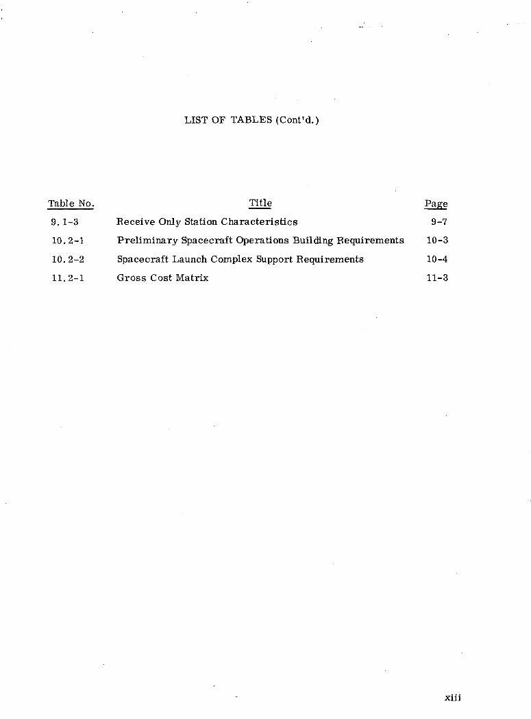
LIST OF TABLES (Cont'd.)
Table No. Title Page
9.1-3 Receive Only Station Characteristics 9-7
10.2-1 Preliminary Spacecraft Operations Building Requirements 10-3
10.2-2 Spacecraft Launch Complex Support Requirements 10-4
11.2-1 Gross Cost Matrix 11-3
Xlll

SUMMARY
The objective of the Applications Technology Satellite Advanced
Mission Study was to develop several approaches to the design of a
spacecraft capable of demonstrating the feasibility of high power
microwave communication satellites which produce shaped multi-
beams to illuminate desired areas of the earth. Additionally, the
satellites are suitable for use in the demonstration of information
networks comprised of small user terminals.
Included in the scope of the work accomplished was the preliminary
design of several possible spacecraft approaches and the associated
prime experiments together with supporting analysis and tradeoff
studies. Additional experiments compatible with the capabilities of
the spacecraft were defined. The program implications, such as
gross implementation schedules and resources; manufacturing, test
and support; and critical research and development requirements were
identified.
This report identifies potential users of wideband information net-
working systems whose operations would be enhanced by the use of a
high power microwave communication satellite in geostationary orbit
operating into small earth terminals. These potential users require
technical data, operational experience, and hardware prove-out before
committing their resources. An Applications Technology Satellite
designed to meet this requirement is the ideal response to the require-
ment for the experimental data, experience and hardware
that is essential for system specification.
~The-Titan-IU G launched spacecraft-versions were-fomuHo-be the
most suitable for meeting the objectives.
XIV
SECTION 1
INTRODUCTION
This document is the result of a study performed at Fair-child
Industries Space and Electronics Division under NASA contract
NAS3-14360 and Amendment Number 1 issued by the Lewis
Research Center. This section describes the scope of the study
and the constraints under which it was performed as directed by
the Statement of Work.
1. 1 MISSION OBJECTIVES
The study was performed with the aim of providing sound techni-
cal plans for developing an Applications Technology Satellite whose
main mission objectives are to demonstrate the feasibility of high
power communication satellites using shaped multibeams and to
demonstrate the use of such satellites in the development of informa-
tion networks comprised of small user terminals.
1.2 STUDY OBJECTIVES
The objective of this study has been to develop a document present-
ing several approaches to the design of a spacecraft capable of ful-
filling the mission objectives described above. Specifically the
study included:
o Definition of three possible spacecraft approaches and associated
prime experiments,
o Analysis of the approaches including tradeoffs and comparisons.
o Definition of additional experiments utilizing the capabilities
of the spacecraft.
1-1
• Identification of critical research and development require-
ments „
• Determination of hardware and facilities requirements for
manufacturing, test and support.
• Determination of gross implementation schedules and estima-
tion of the resources required.
1. 3 CONSTRAINTS
The study was performed under a certain set of constraints imposed
by the Statement of Work. These constraints are outlined below.
1. 3. 1 GENERAL CONSTRAINTS
• The projected first launch date is 1976
• The spacecraft is placed in geostationary orbit
• The spacecraft operates for a minimum period of two years
with all subsystems operating within specification
1.3.2 BOOSTERS
The following three launch vehicles were considered:
• Titan IHC (ATS - AMS III A and B) Figure 1.3. 2-1
• SLV3C CENTAUR (ATS-AMS II)* Figure 1. 3. 2-2
• TAT (9c)/DELTA (ATS-AMS I) Figure 1. 3.2-3
Apogee kick motors, Burner EL, and electric third stage were con-
sidered for final orbit injection,
1.3.3 SPACECRAFT POSITIONING
• The attitude control permits antenna beam pointing accuracy of
± 0„2° at the sub-satellite point and ± 0.2° in rotation about the
bore sight axis for five years
• This series vehicle will be superceeded in the 1976 time period.Launch vehicles considered in the study were SLV3D/CentaurD -- 1A/Burner II (ATS-AMS tt) and Delta 2910.(ATS-AMS I). ...._
1-2
inbo
inoo
COCOCO
o 3
j £
CO M «-2 •*«* 3
^ COOS
OCQ
Ein
C9
QC
Q.CO
>• Q£
O£
etfH-l
O
is
cQJa
oCDP
5B
go<uo
§•l-l(0CO
O
§T3
COH
(M
co
tu
be
LLf
•tocoLUO
o.CO
^io «^co K - x- o2 z 2 z « u& coa"8 E 5 ^ > - => ««— as z i f i c o >< a ~>H- <»- CO L U L U Z
1-3
a:o
oa
a>JH3pq
iP
^Ia0)O"
co>i-lCQ
01Oen
0)f-<
P
R
a>ort
o'ww
CUO
I13
TOH
IM
CO
cuJ-lg>•S-—°—x-O u- LU
1-4

5O31
t3CU
•sc,a
o
cso
t— t
aOoco
pCCDO0)
CSV»O<UO
o
01
%•d
<uo
\03
co
CO
0)
1-5
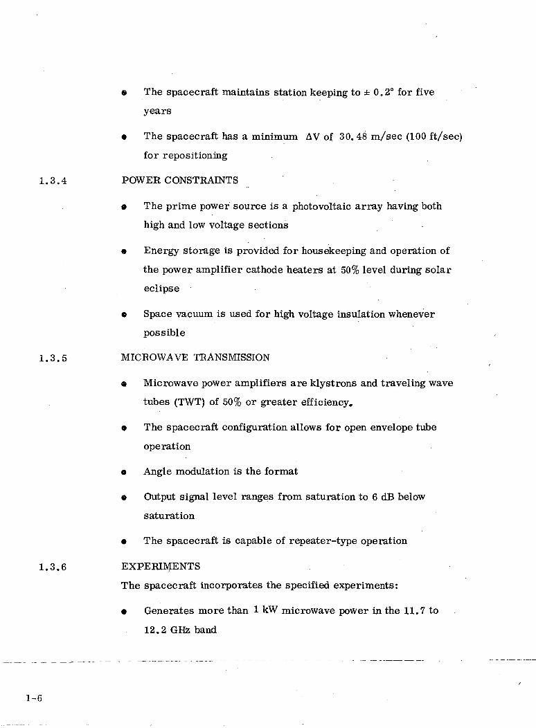
e The spacecraft maintains station keeping to ± 0.2° for five
years
• The spacecraft has a minimum AV of 30.48 m/sec (100 ft/sec)
for repositioning
1.3.4 POWER CONSTRAINTS
0 The prime power source is a photovoltaic array having both
high and low voltage sections
• Energy storage is provided for housekeeping and operation of
the power amplifier cathode heaters at 50% level during solar
eclipse
9 Space vacuum is used for high voltage insulation whenever
possible
1.3.5 MICROWAVE TRANSMISSION
« Microwave power amplifiers are klystrons and traveling wave
tubes (TWT) of 50% or greater efficiency,
9 The spacecraft configuration allows for open envelope tube
operation
a Angle modulation is the format
o Output signal level ranges from saturation to 6 dB below
saturation
o The spacecraft is capable of repeater-type operation
1.3.6 EXPERIMENTS
The spacecraft incorporates the specified experiments:
• Generates more than 1 kW microwave power in the 11.7 to
12.2 GHz band
1-6

• Generates multibeam shaped patterns for the controlled
illumination of desired areas on earth with contoured beam
patterns
o Generates high power with solar arrays
o Uses gallium liquid metal slip rings for efficient power trans-
fer from solar array to spacecraft body
e Demonstrates efficient methods for heat rejection from the
transmitter power amplifier
• Demonstrates multibeam transmission to and from small
ground terminals
9 Directly generates high voltages from chains of solar cells
In defining other experiments, satellite to satellite communications,
optical space to earth communications and station sensing by opti-
cal methods were considered.
1.4 REACTOR-THERMOELECTRIC POWER SYSTEMS
During the final weeks of the Advanced Mission Study period, two
meetings were held between personnel from the U. S. Atomic Energy
Commission and Fairchild Industries to discuss the possibility of
utilizing a nuclear electrical power source as an alternative to the
photovoltaic array. Available time and resources did not permit a full
tradeoff study, but a report was provided by the Space Nuclear Systems
Reactor Power Systems Branch and is included as Appendix A of this
report so as to provide all of the available material in a single
compilation.
1-7
SECTION 2
HIGH POWER COMMUNICATION SATELLITE MISSIONS
2.1 MISSIONS AND REQUIREMENTS
Existing point-to-point communication satellite systems utilize a
satellite producing relatively modest effective isotropic radiated
power (e.i. r.p.) in conjunction with a limited number of sophisti-
cated earth terminals in order to achieve the necessary level of
system performance. Technology advancements makes it econo-
mically attractive to implement networking systems with satellites
of higher e.i. r.p. achieved through the use of efficient power ampli-
fiers, contoured beam pattern antennas and related equipment, serv-
ing many simplified earth terminals.
For an application requiring a given satellite e.i.r.p. for reception
by earth terminals having given antenna and receiver characteristics,
consideration must be given to the relative influence of the satellite
transmitter power and antenna gain in providing this e.i.r.p. The
gain provided by the antenna is, of course, inversely related to its
beamwidth or coverage area. Therefore, the required earth cover-
age area limits the gain available from the satellite antenna. In an
application requiring only spot coverage, the satellite antenna can
provide a greater proportion of the e.i. r.p., thus relaxing the trans-
mitter power requirements. However, for an application requiring
large area coverage to small earth terminals, such as would be the
case for an information networking satellite, the satellite antenna
gain is limited and this application can be satisfied only by a high-
power satellite transmitter.
2-1

Another system consideration relating to antenna gain or beamwidth
is the problem of antenna orientation. A highly directional satellite
antenna imposes strict limitations on satellite attitude. Similarly,
a highly directional earth station antenna makes initial installation
alignment difficult, is subject to perturbations due to adverse
weather, imposes limitations on satellite station-keeping, and re-
quires that it have tracking capability, which is not economically
feasible for a small station. Again, the use of high satellite trans-
mitter power is the solution.
Ideally, the satellite antenna pattern footprint would exactly fit the
contour of the service area with a uniform and adequate signal
strength to conserve power and minimize interference with other
services. Unfortunately, service areas are nearly always of an
irregular contour, and simple beam antennas deliver circular or
elliptical footprints. As the following sections of this report will
show, multibeam antennas producing contoured patterns are feasible,
and - although there is a power loss in the satellite in deriving the
contoured patterns - power conservation is achieved.
The application of these high-power technologies to communication
satellites serving information networking systems comprised of many
small terminal users makes the realization of the promise of innovative
solutions to the problems of education, health care delivery and
other areas of public concern near at hand. There are real needs
by prospective users for operational wide-band information net-
working systems employing high power geostationary satellites.
These prospective users require experimental data and actual
demonstration experience to more fully understand how to best
obtain the desired benefits and to appreciate the limitations of those
systems.
By performing information networking experiments, they can gain the in-
sight required to properly configure and specify their operational systems
2-2
and to confidently commit public resources for the earth terminal
hardware, software, personnel and training. An ATS-AMS con-
figured to facilitate a working demonstration for several representative
systems is the ideal response to these user needs.
2.2 BASELINE INFORMATION NETWORKING EXPERIMENTS
A number of information networking baseline experiments were
developed for the Advanced Missions Study. Several are discussed
in the following section.
2.2.1 PUBLIC BROADCASTING SYSTEM NETWORKING EXPERIMENTS
This experiment would provide experience and background in the
utilization of a communication satellite for the PBS Interconnecting
Service. As shown in Figure 2.2-1, program material would be
provided for each of the four CONUS time zones plus the states of
Alaska and Hawaii from the six originating stations. Over two
hundred non-commercial television stations would receive the prog-
ram material for local broadcasting. Storage centers in the Central,
Mountain, and Pacific Zones would provide the appropriate time
delay.
Several system configurations would be available to the service. Ten
high quality relay channels would permit full time coverage of two
independent TV channels to each of the five time zones. The ATS-
AMS would relay the program material from the originating/storage
station(s) in each time zone to the PBS stations with multibeam ant-
enna patterns closely fitted to the contour of the zone for efficient
usage of power.
2-3

<• to
o irJ
a ge £to
Ero
OQ"
O
O
O
<§>- tO
£ <E >o zo o>LulOLulC£
tozo
5to
QQct:too
orsi
to•Si<cto
>-
C£
<:(V
0
O
CQ
o
iO
c01
exXw
O
•4-1CL>
OSctf
IO
CO
PQ
enrt
PQ
CQ
COH
01
2-4

Other configuration options include a reverse feed capability. The
ATS-AMS would make available a means to route program material
from properly equipped PBS stations or remote pick-up vans back to
a network center for coordination and redistribution.
Through frequency reuse techniques such as polarized antenna feeds
and buffer zone spacing, only six frequencies are necessary to ser-
vice the ten channels. Referring to Figure 2.2-1, the Eastern Time
Zone would be assigned frequency channels A and B. The adjacent
Central Time Zone would be assigned Channels C and D. These
same four frequencies would also be assigned as channels A' and B1,
C' and D1 for the Mountain and Pacific Time Zones respectively, with
additional isolation achieved through cross polarization of the earth
terminal antennas. Alaska and Hawaii coverage would utilize the
5th and 6th frequencies.
2.2-2 SPECIAL INTEREST AREAS EXPERIMENT
Throughout the United States, there are areas where PBS television
reception is difficult if not impossible due to the terrain or lack of
a nearby PBS outlet. With relatively modest receiving equipment
(as compared to the PBS broadcasting station); good quality televi-
sion could be displayed, for instance, at schools, community cen-
ters, and other appropriate places for public gathering. Outlined
in the CONUS Figure 2.2-2 is the Appalachian area and the area
serviced by the Federation of Rocky Mountain States (Arizona and
Nevada are reported not to be members at this writing) where this
service would be particularly beneficial.
2.2.3 RAINFALL ATTENUATION EXPERIMENT
A problem most peculiar to the southeastern region of the United\
States is the possibility of temporary outages due to increased
attenuation during heavy rainfall. The ATS-AMS multibeam antenna
would permit increasing the power to the particular feed(s) associ-
ated with the outage link to correct the problem. (See Figure 2. 2-3.)
2-5

0
2-6

2-7

2.2.4 CULTURAL REGION INTERACTIVE TV EXPERIMENT
As shown in Figure 2.2-4, ten centers are identified throughout six
cultural regions in the CONUS. This experiment would provide addi-
tional background and experience in interactive in-school instruc-
tional television, computer-aided instructional television, medical
information and remote diagnosis, etc. Experiments with a wide
variety of interactive services could be facilitated. For example:
« Prominent Lecturer - A service can be envisioned to bring the
knowledge and personality of prominent individuals to persons re-
siding in a given region for a continuing education series. Stu-
dents would observe and hear the lecturer on a conventional tele-
vision display and would interact with the lecturer by means of
voice response circuit. Total "classroom" attendance would be
limited in size as it is with a conventional classroom; i.e., a
maximum of about 30. An attractive option for quadrupling the
number of simultaneous classes would be the use of frame rates
on the order of 6 to 8 per second rather than the standard 30.
This would not be a serious compromise since the actions of a
lecturer and the display of material such as visual aid charts
does not entail a great amount of motion.
0 Popular Classroom - Increasing the size of an individual class
necessitates restrictions in the degree of interaction between an
instructor and the individual student. A service to classroom
sizes limited by the channel capacity of the satellite could make
use of a multiple choice response, say on the order of 5 choices.
A large number of classrooms distributed throughout the region
could observe the presentation on a conventional television dis-
play. Periodically, the instructor conducts a short multiple
choice quiz, with the students entering their response on a small
attachment at each desk. The results could be instantaneously
2-8

CODC
O LUID O
^ -"2 iQ O> O
LU^ o;
oC£UL.
0E•—i oo
oo•o
co
co —
O QQ
O ^CO I—.<f CO
LU
OLUOH
co_iO,ooCO ro
o:LU
O
oLUo;
oorr\
.O<co
ooQ
cOJ
s•c01axWbe
<u^co
'T-t±JBJ
a!i
.2c
a>
o>-4->
be0)
oOlc
•p^
"3wrtmEcc
cc
T(M
OJ
(U
2-9
scored and recorded in each remote classroom, tabulated and
transmitted to the origination center where the totaled response
would be displayed to the instructor. He would then have an in-
dication of the level of comprehension in his distributed classes
and would proceed accordingly.
Computer-Aided Instructional Television - Through the use of
a computer directed access library at the regional origination
center with keyboard terminals and television display "frame
grabbers" in the classrooms, students would have the capability
to pursue an array of research and programmed instruction
courses.
The ATS-AMS would provide ten independent video channels for
allocation among the six regions. Assuming one channel per origina-
ting center, no more than two channels would be allocated to a given
region. Therefore, only six frequencies would be utilized. Again,
additional isolation would be achieved through antenna cross polariza-
tion in addition to buffer zone spacing.
The ATS-AMS would incorporate a capability for one talk-back trans-
ponder per regional center. Each transponder would accommodate
up to 25 audio channels per transponder or 6, 250 low speed data circuits.
Through operational queing, the number of participants would be
primarily limited by the user peripheral equipment.
2-10
2. 2. 5 ALASKA MEDICAL INFOBMATION NETWORKING EXPERIMENT
It has been dramatically demonstrated through the early ATS Space-
craft and elsewhere that medical information transmitted via
communications networks can save lives in areas such as Alaska.
An experiment to demonstrate the benefits of a two-way video/voice/
data transmission capability between isolated regions and supporting
services, such as The National Library of Medicine or cooperating
medical centers in the Continental United States can be viewed as
as a step in the direction of establishing a medical services program
covering the entire State of Alaska. The services provided can be
in the form of diagnostic assistance, or can be in the form of medi-
cal information for upgrading paramedical personnel capabilities.
2. 2. 6 EXPERIMENT PLANNING AND COORDINATION
It is important to recognize that attention must be addressed to the
entire area of experiment planning and coordination with the users.
Studies, possibly including physical simulations, are necessary to
establish methods and techniques for the information. networking
experiments, such as multipoint multiple access cueing and control
techniques.
Having the capability and the flexibility to provide service to unsophi-
sticated earth terminals, the ATS-AMS would be valuable to many
other information networking experiments. Section 7.2 discusses
these in detail.
2-11
SECTION 3
ASCENT TRAJECTORIES AND LAUNCH SEQUENCES
Three ascent trajectories and four launch vehicles were considered
during the study with the following combinations being recommended
for continued consideration.
& Direct ascent to geosynchronous equatorial orbit using a
current Titan El C and a growth version
o Direct ascent to geosynchronous equatorial orbit using an Atlas,
Centaur/Burner n launch vehicle combination
o Injection into a 28.5° inclined parking orbit below the Van Allen
belt using a Delta 2910 launch vehicle combination and orbit
raising to geosynchronous equatorial by means of 30 cm Mer-
cury ion thrusters
Injection into a 28.5° inclined parking orbit above the Van Allen belt
using a Titan m B/Tandem Bn launch vehicle combination and orbit
raising to geosynchronous equatorial orbit with ion engines was also
considered but the payload capability does not appear adequate for
more than a minimal mission.
Highlights of the trajectory and launch vehicle analyses are given
in the following subsections.
3.1 TITAN m C TRAJECTORY AND LAUNCH SEQUENCE
3.1.1 LAUNCH VEHICLE CHARACTERISTICS AND CAPABILITIES
The Titan in C launch vehicle is a four stage vehicle consisting of
two 5-segment solid fuel rocket motors, a standard core and a Transtage.
3-1
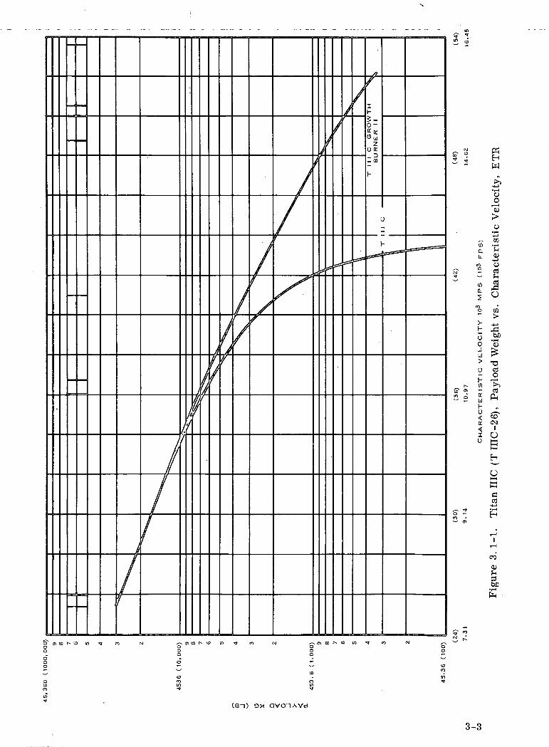
The payload capability into a synchronous equatorial orbit (character-
istic velocity 11.9 meters/second (39 ft/sec) is currently quoted at 1, 550 kg
(3, 423 Ibs). An increased payload capability of 1724 kg (3900 Ibs)
can be obtained by adding a Burner n above the Transtage. However,
a recent communication from the Martin Marietta Denver Division
indicates that further hardware improvements and trajectory opti-
mization to the Titan HI C could realize payload capabilities of up
to 1724 kg (3900 Ibs). The payload capability vs launch mission character-
istic velocity for the current Titan m C is shown by Figure 3.1-1.
Payload adapters trusses and separation devices are considered to
be a part of the payload.
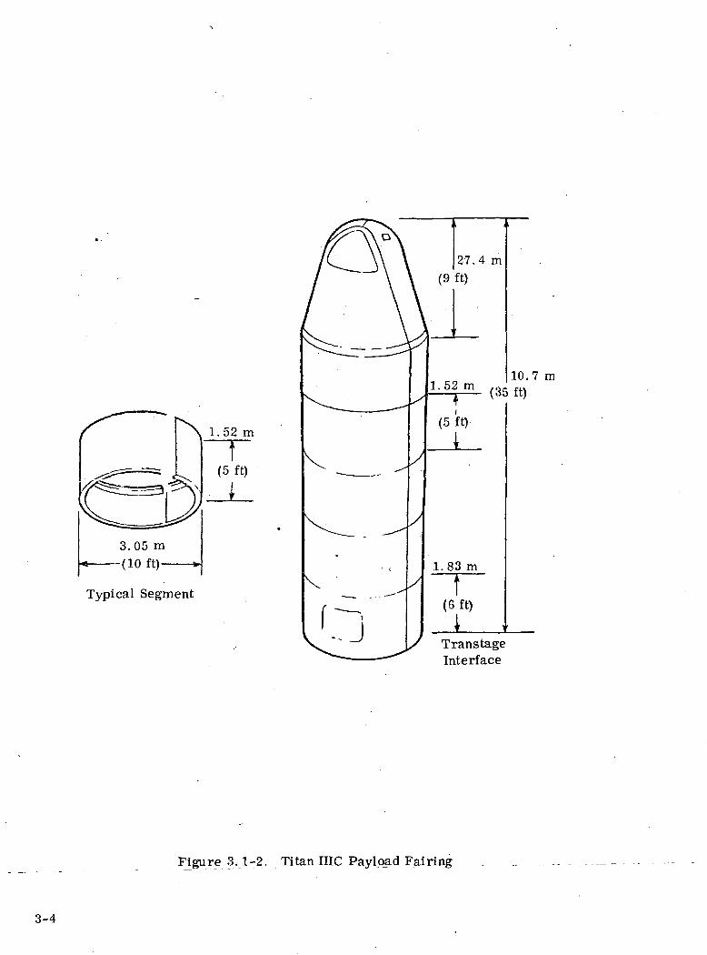
The payload fairing for the Titan HI C is 3.05 m diameter and 10. 7 m
long (35 ft) . A sketch of this fairing is given in Figure 3. 1-2. The
Titan HI C profile is shown by Figure 3.1-3. The payload fairing
is fully developed and is currently in use for all Titan m C vehicles.
3.1.2 ASCENT TRAJECTORY
The Titan HI C is launched from the Eastern Test Range at 93°
azimuth and ascends to a parking orbit with an altitude of 167 km (104 mi).
At the first equatorial crossing (descending node) the transtage
places the spacecraft into an elliptical transfer orbit with apogee at
synchronous altitude of 35, 786 km (22, 000 mi). At the apogee equatorial
crossing (ascending node) the Transtage performs a second burn and
places the spacecraft into synchronous equatorial orbit. A ground
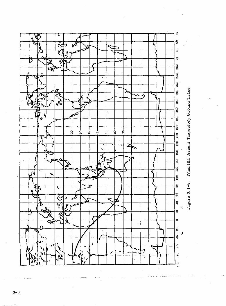
track of this standard ascent trajectory is given in Figure 3.1-4. As
shown by this figure, the spacecraft achieves synchronous orbit
south of Malaysia. To place the spacecraft south of the United
States, either an eastward drift to station is required or an ascent
trajectory which requires multiple equatorial crossings in either
the parking orbit or the transfer orbit. Minimum weight and time
penalty occurs if injection into transfer orbit occurs at the second
parking orbit equatorial cipssing (ascendmgnode)^nd injection mto
3-2
z0 D:_ D-CD
"o
>-h0 £»0 01
llJ >>
i I
K
H
f>•i—io
"QJ
o• i—i-4-1CO
• r-»
0>
B03
o
T3
§h T-
Oe
OI—ICda)
oo0)fH
N m co J^ 10 in *» en
3-3
1.52 m
t(5 ft)
Typical Segment
10.7 m
Trans tageInterface
Figure 3.1-2. Titan IIIC Pay load. Fairing _
3-4

I
3. 3 m(108.
1
i
J
2 ft)
2.58 m(84.5(Stage
]
i
ft)• 0 )
1 i
A5
4
3
2
1
L>\
3.05 m(10.0)
" '''' "Iii 1
JL*/
/ \
^ 7
X
PayloadInterface
(Trans tage)
1. 9 m (6 .2 f t ) '
Stage II/HI 'Separation
(29
A ,3.3 m
(10.0)
-<.
-1 \
t
(72
k 1
l
8.8 m0 ft) (Stage II)
1 Stage I/IISeparation
2.22 m. 9 ft) (Stage I)
L_
Figure 3. 1-3. Titan IIIC Profile
3-5
o
•o
§5-1O
f-loo
CO)OCQ
O
I
co0)
bO•pH
f*
3-6

synchronous equatorial orbit occurs at the first apogee equatorial
crossing (ascending node) . The orbit errors that can be expected
with a Titan in C launch are as follows:
apogee altitude 352 km (218 mi)
perigee altitude 326 km (202 mi)
period error ±11 min
orbit eccentricity .0066
inclination error ±0165deg
geocentric longitude ± ,2 deg.
The period error is equivalent to a station change of ±2. 75 degrees
per day.
3.1.3 LAUNCH SEQUENCE
A typical launch sequence for the Titan III C is tabulated in
Table 3. 1-1 and illustrated in Figure 3. 1-5.
3-7

Table 3.1-1. Titan in Typical Flight Sequence
Time (Sec) Description
0
>- 10
20
30
80
108.77
111.70
122.85
126.00
131.00
258.24
258.94
289.00
450.00
462.56
476.06
1350.19
1656.59
20422.00
20529.99
20647.99
Liftoff from ETR LC 40, begin vertical rise.
Start pitchover with inertial pitch rate.
Start angle-of-attack attitude control.
Begin zero-lift flight.
Terminate zero-lift flight; initiate inertial pitch rate.
Acceleration of 2.18 g; start staging sequence.
Stage I ignition; simulated thrust buildup.
Solid rocket motor jettison.
Initiate inertial pitch rate.
Initiate inertial pitch rate.
Initiate Stage I tailoff Stage II ignition.
Jettison Stage I.
Jettison payload fairing.
Initiate inertial pitch rate.
Initiate Stage II tailoff.
Jettison Stage II, park orbit inject.
Start first Stage III burn.
First Stage III shutdown; inject into final transfer orbit.
Start second Stage III burn.
Second Stage III shutdown; inject into final orbit;begin vehicle reorientation.
End vehicle reorientation; jettison payload forwardof Station 77 into a 35, 786 km circular orbit.
3-8

H
c/J
S'£Q
W
T3
s8OJ
" -Q
2 "2o°£l02 -•« so 2
S3o
3-9
3.2 ATLAS/CENTAUR/BURNER H TRAJECTORY AND LAUNCH
SEQUENCES
3.2.1 LAUNCH VEHICLE CHARACTERISTICS AND CAPABILITIES
The Atlas SLV-3D/Centaur D-1A is a two stage liquid propellant
launch vehicle that is capable of injecting a payload of 1860 kg
(4100 Ibs) into a 185 x 35, 786 km (100 x 19, 323 nautical miles)
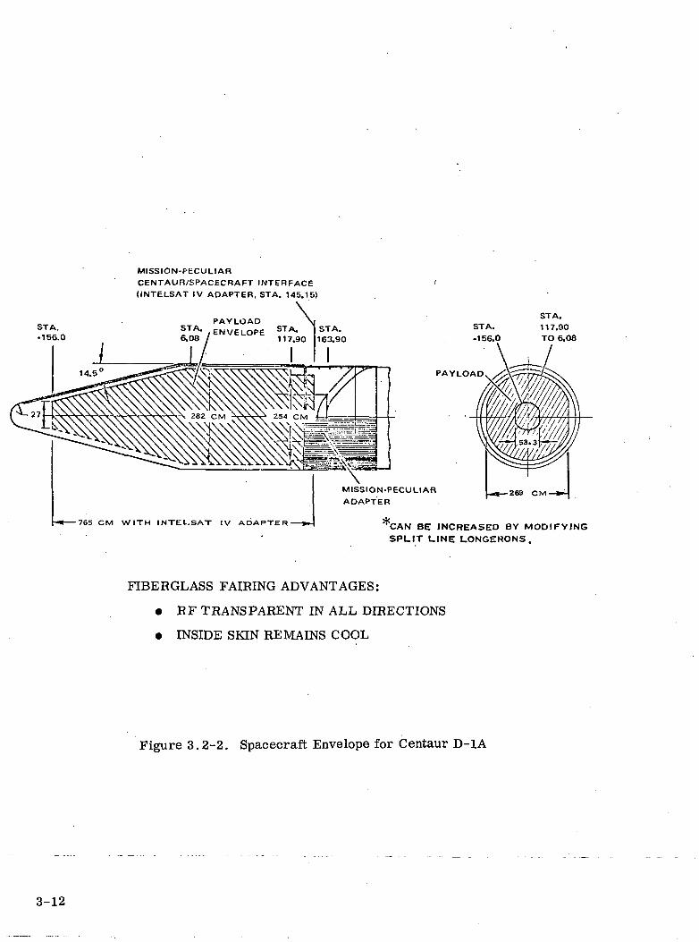
elliptical transfer orbit. The overall Atlas/Centaur Profile is
shown by Figure 3.2-1 and the allowable Spacecraft envelope is
shown by Figure 3. 2-2. The Burner II structure and the Burner/
Centaur interfaces are shown on Figure 3.2-3. The Burner can ac-
commodate either the TE-364-3 or TE-364-4 apogee kick motors
which under standard conditions of propellant loading have the
following total impulse capabilities.
TE-364-3 190,058 kg-sec (419,000 Ib-sec) ± 6%(I = 287 sec)SP
TE-364-4 358, 344 kg-sec (790, 000 Ib-sec) ± .75% (I = 284 sec)SP
The Burner II is an inertially guided stage and takes its attitude re-
ference from the Centaur at separation. A recent telephone con-
versation with Convair San Diego indicated that the three Sigma
accuracy of vehicle attitude at transfer was ±1.2°.
The AKM can be offloaded or extended to accommodate the exact
payload requirements with the propellant with the propellant weight
determined by the relationship- AV
Wf = Wp (1-e glsp
The Atlas Centaur normally utilizes a 185 km (100 mi) altitude parking
orbit with a transfer orbit 185 x 35, 786 km (19, 323 n mi) inclined at 28. 5°
to the equator; the required AV at apogee is 183 m/sec (6000 ft/sec). It is
possible to make a plane change at perigee to match a payload with-the —
3-10

T
39.9 m (131 FT)
JL
NOSE FAIRING
PAYLOADCOMPARTMENT
JETTISONABLEINSULATION PANELS
CENTAUR D-1A
INTERSTAGEADAPTER
4TLAS SLV-3D
Figure 3.2-1. Atlas/Centaur Configuration
3-11
MISSION-PECULIAR
CENTAUn/SPACECRAFT INTERFACE(INTELSAT IV ADAPTER. STA. 145.15)
STA.•156.0
•765 CM WITH INTELSAT IV ADAPTER
PAYLOAD
MISSION-PECULIAR
ADAPTER
CAN BE INCREASED BY MODIFYING
SPLIT LINE LONGERONS.
FIBERGLASS FAIRING ADVANTAGES:
• RF TRANSPARENT IN ALL DIRECTIONS
• INSIDE SKIN REMAINS COOL
Figure 3.2-2. Spacecraft Envelope for Centaur D-1A
3-12

Thermal Bulkhead
Burner II Adapter& Equipment Bay
StrengthenedSurveyor Adapter
No«e Fa/ringRestraining link
Uwt
Figure 3.2-3. Burner II/Centaur Physical Interface
3-13
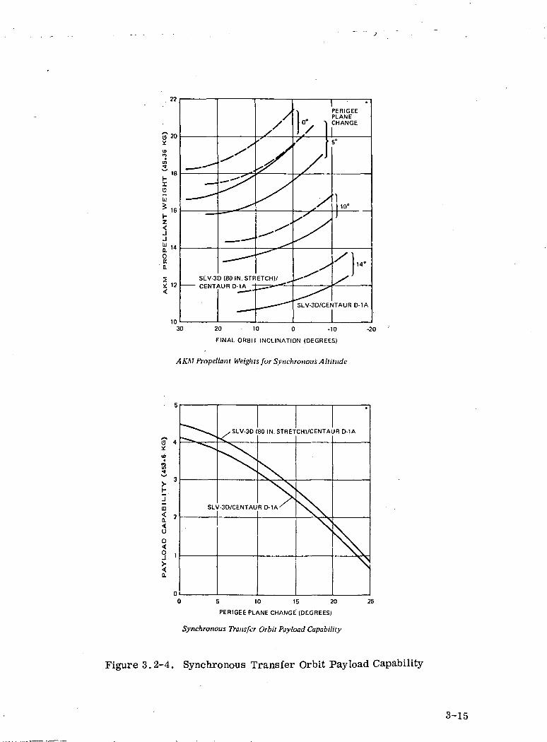
standard propellant loading of an apogee kick motor. Figure 3.2-4
shows the synchronous transfer orbit payload capability as a
function of perigee plane change and the AKM propellant weight re-
quirement as a function of final orbit inclination. As an example,
the burnout weight of an apogee impulse Burner II with full time
telemetry and coast control is 155 kg (341 Ibs) and the propellant
weight with a TEM-364-3 AKM is 660 kg (1453 Ibs). Using this pro-
pellant loading and a final orbit inclination of 0 and a perigee plane
change of 10 the synchronous transfer orbit payload including the
spacecraft adapter would be 1450 kg (3200 Ibs). It is also possible
to use the Convair OV1-B as an apogee kick stage. The OV1-B also
uses the Thiokol TEM-364-3 and-4 motors and has compatible per-
formance to the Burner II.
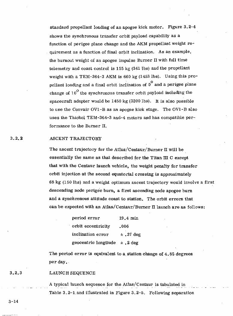
3.2.2 ASCENT TRAJECTORY
The ascent trajectory for the Atlas/Centaur/Burner n will be
essentially the same as that described for the Titan m C except
that with the Centaur launch vehicle, the weight penalty for transfer
orbit injection at the second equatorial crossing is approximately
68 kg (150 Ibs) and a weight optimum ascent trajectory would involve a first
descending node perigee burn, a first ascending node apogee burn
and a synchronous attitude coast to station. The orbit errors that
can be expected with an Atlas/Centaur/Burner n launch are as follows:
period error 19.4 min
orbit eccentricity .006\
inclination error ± .37 deg
geocentric longitude ± . 2 deg
The period error is equivalent to a station change of 4.85 degrees
per day.
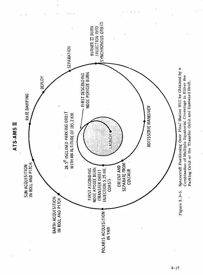
3.2.3 LAUNCH SEQUENCE
A typical launch sequence for the Atlas/Centaur is tabulated in
Table 3. 2-1,and illustrated in Figure 3.2-5. Following separation
3-14
AK
M
PR
OP
EL
L.A
NT
W
EIG
HT
(4
S.3
6 K
G)
-*
_t
—
— t
—
M
N0
N)
*>
01
00
O
N
^
-^
SLV-3
/"'
^
— ^
D (80IN.STF
-. —
X,'V^/
>
--^
ETCH)/ ^
- -
I)/)^
XJS
/
X >
s
SLV-3D/CE
•
PERIGEEPLANECHANGE
15°
1|10«j
/],,
/
V1TAUR D-1A
0 20 10 0 -10 -2
FINAL ORBIT INCLINATION (DEGREES)
AKM Propellant Weights for Synchronous Altitude
SLV-30 (80 IN. STRETCH1/CENTAUR D-1A
) 5 10 15 20
PERIGEE PLANE CHANGE (DEGREES)
Synchronous Transfer Orbit Payload Capability
Figure 3.2-4. Synchronous Transfer Orbit Payload Capability
3-15
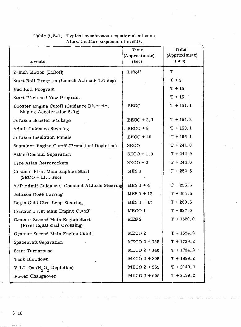
Table 3.2-1. Typical synchronous equatorial mission,Atlas/Centaur sequence of events.
!
Events
2 -Inch Motion (Liftoff)
Start Roll Program (Launch Azimuth 101 deg)
End Roll Program
Start Pitch and Yaw Program
Booster Engine Cutoff (Guidance Discrete,Staging Acceleration 5.7g)
Jettison Booster Package
Admit Guidance Steering
Jettison Insulation Panels
Sustainer Engine Cutoff (Propellant Depletion)
Atlas/Centaur Separation
Fire Atlas Retrorockets
Centaur First Main Engines Start(SECO + 11.5 sec)
A/P Admit Guidance, Constant Attitude Steering
Jettison Nose Fairing
Begin Guid Clsd Loop Steering
Centaur First Main Engine Cutoff
Centaur Second Main Engine Start(First Equatorial Crossing)
Centaur Second Main Engine Cutoff
Spacecraft Separation
Start Turnaround
Tank Slowdown
V 1/2 On (HgO Depletion)
Power Changeover
Time(Approximate)
(sec)
Liftoff
BECO
BECO + 3.1
. BECO + 8
BECO + 45
SECO
SECO + 1.9
SECO + 2
MES 1
MES 1+4
MES 1 + 12
MES 1 + 17
MECO 1
MES 2
MECO 2
MECO 2 + 135
MECO 2 + 140
MECO 2 + 305
MECO 2 + 555
MECO 2 + 605
Time(Approximate)
(sec)
T
T +2
t + 15.
T + 15 '
T + 151.1
T + 154.2
T + 159.1
T + 196.1
T +241.0
T + 242.9
T +243.0
T +252.5
T +256.5
T +264.5
T + 269.5
T + 627.0
T + 1520.0
T + 1594.2
T + 1729.2
T + 1734.2
T + 1899.2
T + 2149.2
T +2199.2
3-16
HCO
COh-
oa.
3-17

from the Centaur, the Burner II and the attached spacecraft
payload would coast to apogee with a coast time of 5. 25 hours.
During the coast period, the Burner II guidance equipment
would perform a slow roll of approximately one-half revolution
per minute to average the gyro drift errors and provide a
better thermal balance for the spacecraft.
3.3 DELTA/ION ENGINE LAUNCH AND INJECTION SEQUENCES
3.3.1 LAUNCH VEHICLE CHARACTERISTICS AND CAPABILITIES
The vehicle configurations currently available for new mission
planning are described by a four digit number, e.g. Delta 2914.
The interpretation of the individual digits is defined as follows:
Number of Solids—
First Stage-i
2
i Second Stage
rThird Stage
1 4
First Stage
0 Long Tank Thor with Rocketdyne Engine - Vehicles of this con-
figuration are shown in the text as containing the last 3 digits
only.
1 Extended Long Tank Thor with Rocketdyne MB-3 Engine.
2 Extended Long Tank Thor with Rocketdyne H-l Engine.
Number of Solids
3,6,9 - Number of First Stage strap-on solid motors.
Second Stage
0 1.65 m (5. 5 ft) diameter second stage and fairing with Aerojet General
AJ10-118F propulsion system
1 2.44 m (8. 0 ft) diameter second stage and fairing with the Aerojet
General AJ10-118F propulsion system.
3-18
Third Stage
0 No third stage.
2 United Technology Center FW-4D.
3 Thiokol TE-364-3.
4 Thiokol TE-364-4.
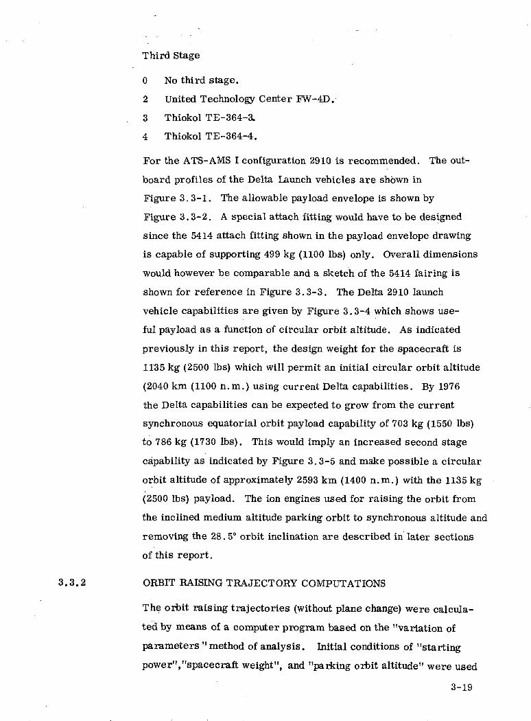
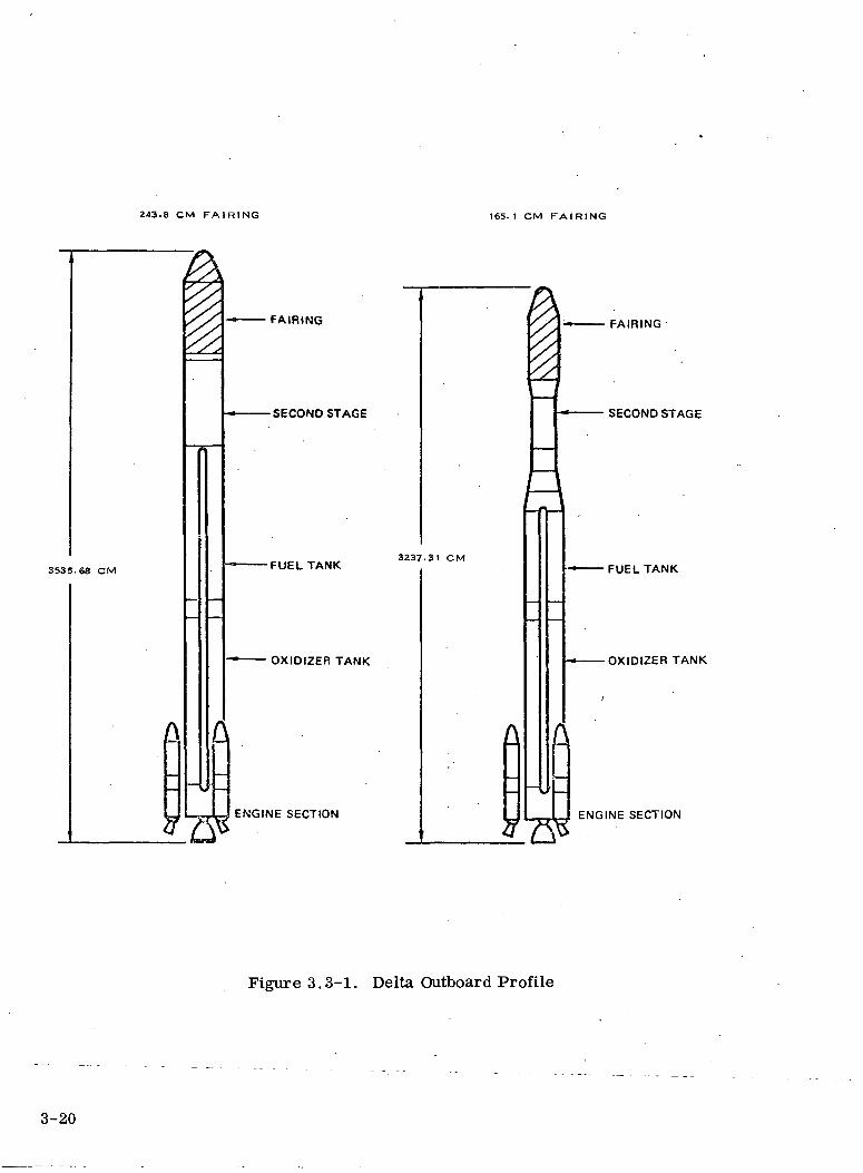
For the ATS-AMS I configuration 2910 is recommended. The out-
board profiles of the Delta Launch vehicles are shown in
Figure 3.3-1. The allowable pay load envelope is shown by
Figure 3.3-2. A special attach fitting would have to be designed
since the 5414 attach fitting shown in the payload envelope drawing
is capable of supporting 499 kg (1100 Ibs) only. Overall dimensions
would however be comparable and a sketch of the 5414 fairing is
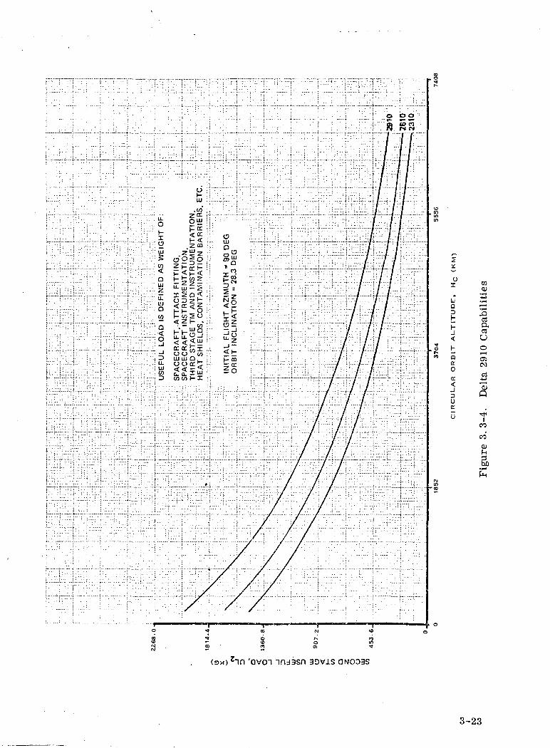
shown for reference in Figure 3.3-3. The Delta 2910 launch
vehicle capabilities are given by Figure 3.3-4 which shows use-
ful payload as a function of circular orbit altitude. As indicated
previously in this report, the design weight for the spacecraft is
1135 kg (2500 Ibs) which will permit an initial circular orbit altitude
(2040 km (1100 n.m.) using current Delta capabilities. By 1976
the Delta capabilities can be expected to grow from the current
synchronous equatorial orbit payload capability of 703 kg (1550 Ibs)
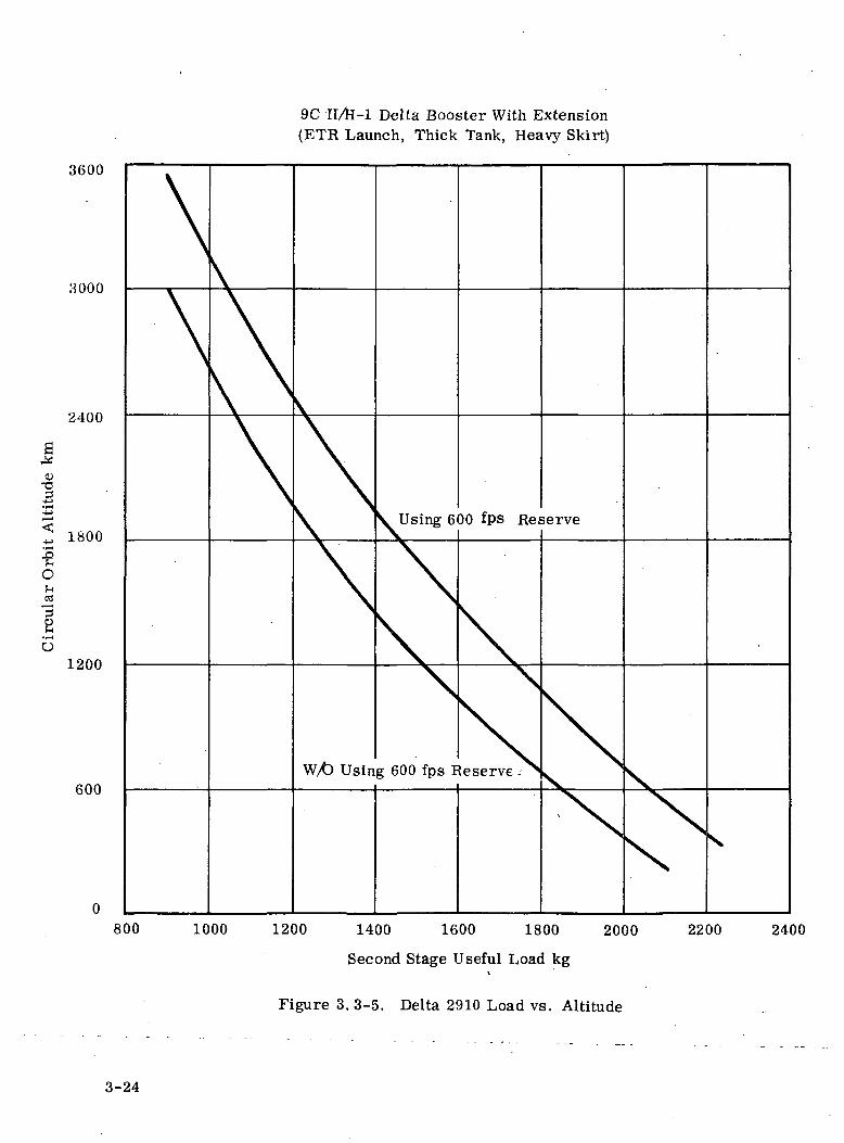
to 786 kg (1730 Ibs). This would imply an increased second stage
capability as indicated by Figure 3.3-5 and make possible a circular
orbit altitude of approximately 2593 km (1400 n.m.) with the 1135 kg
(2500 Ibs) payload. The ion engines used for raising the orbit from
the inclined medium altitude parking orbit to synchronous altitude and
removing the 28.5° orbit inclination are described in later sections
of this report.
3.3.2 ORBIT RAISING TRAJECTORY COMPUTATIONS
The orbit raising trajectories (without plane change) were calcula-
ted by means of a computer program based on the "variation of
parameters '' method of analysis. Initial conditions of "starting
power","spacecraft weight", and "parking orbit altitude" were used
3-19
243.8 CM FAIRING 165.1 CM FAIRING
3535.68 CM
FAIRING
•SECOND STAGE
•FUEL TANK3Z37.31 CM
OXIDIZER TANK
£
ENGINE SECTION
FAIRING
SECOND STAGE
FUEL TANK
•OXIDIZER TANK
ENGINE SECTION
Figure 3.3-1. Delta Outboard Profile
3-20
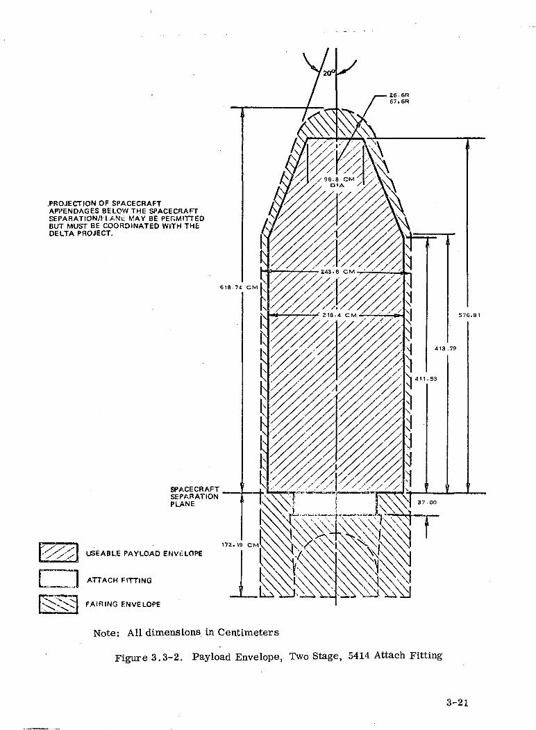
.PROJECTION OF SPACECRAFTAPPENDAGES BELOW THE SPACECRAFTSEPARATION/H.ANU MAY BE PERMITTEDBUT MUST BE COORDINATED WITH THEDELTA PROJECT.
EH
SPACECRAFTSEPARATIONPLANE
USEABLE PAYLOAD ENVELOPE
ATTACH FITTING
FAIRING ENVELOPE
Note: All dimensions in Centimeters
Figure 3.3-2, Pay load Envelope, Two Stage, 5414 Attach Fitting
3-21

• 152.083 DIA
Note: All dimensions in Centimeters
Figure 3.3-3. 5414 Conical Attach Fitting Detailed Dimensions
3-22
OI
uQDHhJ
6 h|S. «
n Q]CC0
30
030)
a,rtU
(N
ooeocufns
'oven 3Dvis QNODBS
3-23
3600
3000
2400
0>TJ3
•eot-i<a
B*i—io
1800
1200
600
9C II/te-1 Delta Booster With Extension(ETR Launch, Thick Tank, Heavy Skirt)
W/t> Using 600 fps Reserve -
800 1000 1200 1400 1600 1800 2000 2200 2400
Second Stage Useful Load kg
Figure 3. 3-5. Delta 2910 Load vs. Altitude
3-24
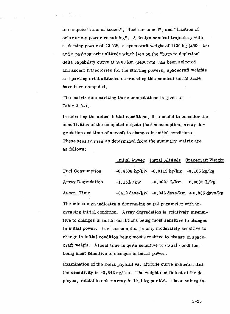
to compute "time of ascent", "fuel consumed", and "fraction of
solar array power remaining". A design nominal trajectory with
a starting power of 13 kW, a spacecraft weight of 1130 kg (2500 Ibs)
and a parking orbit altitude which lies on the "burn to depletion"
delta capability curve at 2700 km (1460 nm) has been selected
and ascent trajectories for the starting powers, spacecraft weights
and parking orbit altitudes surrounding this nominal initial state
have been computed.
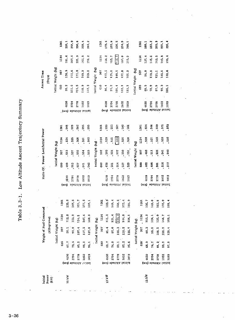
The matrix summarizing these computations is given in
Table 3. 3-1,
In selecting the actual initial conditions, it is useful to consider the
sensitivities of the computed outputs (fuel consumption, array de-
gradation and time of ascent) to changes in initial conditions.
These sensitivities as determined from the summary matrix are
as follows:
Initial Power Initial Altitude Spacecraft Weight
Fuel Consumption -0.4536 kg/kW -0.0115 kg/km +0.105 kg/kg
Array Degradation -1.15%/kW -0.0027 %/km 0.0032 %/kg
Ascent Time -34.2days/kW -0.045 days/km + 0.335 days/kg
The minus sign indicates a decreasing output parameter with in-
creasing initial condition. Array degradation is relatively insensi-
tive to changes in initial conditions being most sensitive to changes
in initial power. Fuel consumption is only moderately sensitive to
change in initial condition being most sensitive to change in space-
craft weight. Ascent time is quite sensitive to initial condition
being most sensitive to changes in initial power.
Examination of the Delta payload vs. altitude curve indicates that
the sensitivity is -0.643 kg/km. The weight coefficient of the de-
ployed, rotatable solar array is 19.1 kg per kW. These values in-
3-25
oa
•-« ~* 04
EH
•SB<*.
•SB
— o« o?— o
in ci en co r-t
oJaI
apn;mv (u«i) (nisi) aptv)i;iv
O
CD CO O CJm m m m
co co m co oo' ' coco m m m m m
Cl)oW
0)
I
co co mCO <H
S COm
s s
3 S
^ oo -H in en oco o co ^ in coj^, r-t tn in tn tn uj
"55 -H
e- oo •-< co •-« «O OO *H CM •**• 'fl'en Tf in in w in
±* o « <o *H . CD t-5 - co -^ ^r tn irt tn
(N ^< *^
CO
00
0)I—I.Q
^1 CD CDCD ..
»-l CO V
- §o> u3 bB
UH O
•S 2£ ~
1 I 3 3 S •H CO -
s eo co tn coO 00 . CO 00
« -i . £
OO 00 O oo oo en
£ P*
3-26
dicate that little is to be gained by increasing the parking orbit
altitude and that increase in initial power will have a significant
effect on only the ascent time and the actual available "start of
mission" power. The net effect however of lowering parking orbit
altitude to increase spacecraft payload capabilities (and hence
spacecraft weight) will be 0.52 kg/km after the effects on solar
array degradation and fuel consumption are considered. Lowering
the parking orbit altitude and increasing the weight as discussed
would increase the ascent time by almost a month.
The previous discussion refers to the problem of raising the orbi-
tal altitude from the nominal design parking orbit to synchronous
altitude without an orbit plane change. For most launch vehicles
and launch sequences, a plane change of 28.5° would also be re-
quired to produce the desired synchronous equatorial orbit. This
could be accomplished after ascent to synchronous altitude but would
extend the time required to attain the mission orbit and would re-
sult in a significant additional expenditure of fuel. A savings in
both time and fuel consumption can be achieved by maneuvering
the spacecraft during ascent to provide a component of thrust
normal to the'trajectory plane.
3. 3,3 LAUNCH SEQUENCES
Typical launch ascent sequences for the two-stage Delta launch
vehicle are tabulated in Table 3.3-2 and illustrated in Figure 3.3-6.
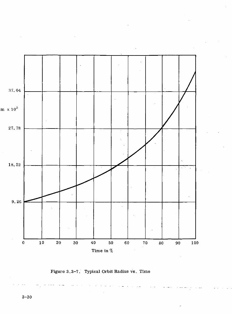
The computer program used to determine the orbit raising ascent
trajectories was given in Appendix C of the interim report together
with an outl ine of the assumptions and relationships used in the
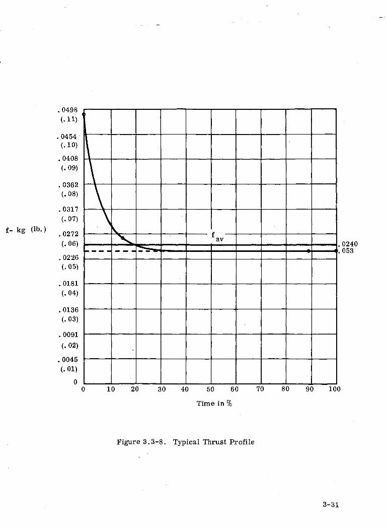
computation. Typical curves of spacecraft altitude vs. normalized
ascent time and ion engine thrust vs. normalized ascent time was
given in Figure 3.3-7 and 3.3-8. A tabulation of synchronous
equatorial orbit injection errors is not appropriate since both the
3-27
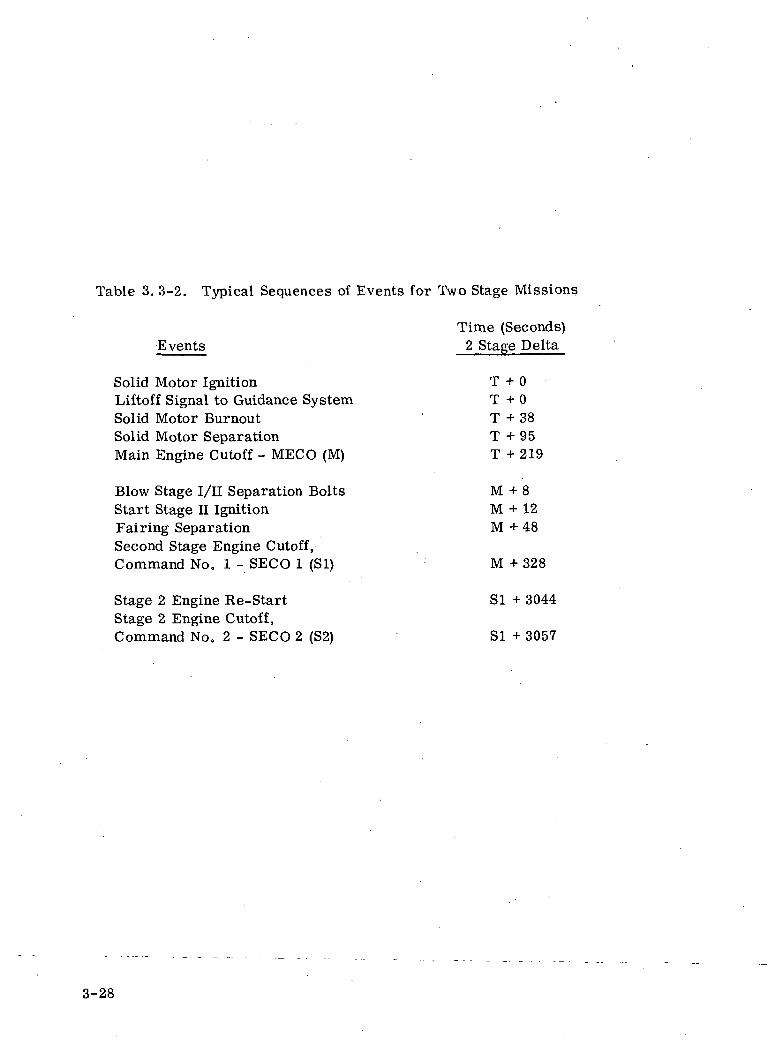
Table 3. 3-2. Typical Sequences of Events for Two Stage Missions
Time (Seconds)Events 2 Stage Delta
Solid Motor Ignition T + 0Liftoff Signal to Guidance System T + 0Solid Motor Burnout T + 38Solid Motor Separation T + 95Main Engine Cutoff - MECO (M) T + 219
Blow Stage I/II Separation Bolts M + 8Start Stage H Ignition M + 12Fairing Separation M + 48Second Stage Engine Cutoff,Command No. I - SECO 1 (SI) M + 328
Stage 2 Engine Re-Start SI + 3044Stage 2 Engine Cutoff,Command No. 2 - SECO 2 (S2) SI + 3057
3-28
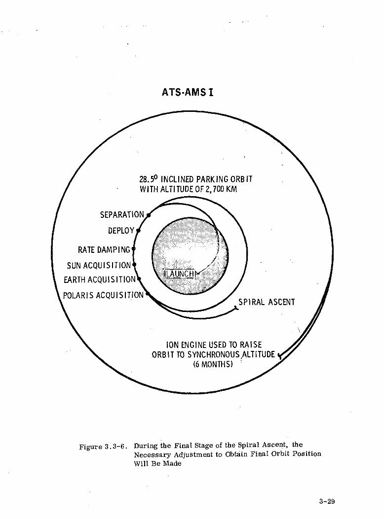
ATS-AMSI
28.5° INCLINED PARKING ORBITWITH ALTITUDE OF 2,700 KM
SEPARATION
DEPLOY
RATE DAMP ING
SUN ACQUISITION
EARTH ACQUISITION
POLARIS ACQUISITION
"(LAUNCH K?
SPIRAL ASCENT
ION ENGINE USED TO RAISEORBIT TO SYNCHRONOUS.ALTITUDE
(6 MONTHS) :
Figure 3.3-6. During the Final Stage of the Spiral Ascent, theNecessary Adjustment to Obtain Final Orbit PositionWill Be Made
3-29
37. 04
m x 10C
27.78
18.52
9.26
0 10 20 30 40 50 60 70 80 90 100
Time in %
Figure 3.3-7. Typical Orbit Radius vs. Time
3-30
f- kg (lb.)
.0498(.11)
,0454(.10)
.0408(.09)
.0362(.08)
.0317(-.07)
.0272(.06)
.0226(.05)
.0181(.04)
.0136(.03)
.0091(.02)
.0045(.01)
0
av.0240'.053
10 20 30 40 50 60
Time in %
70 80 90 100
Figure 3.3-8. Typical Thrust Profile
3-31

altitude and thrust level of the ion engines can be commanded during
the orbit raising phase of the ascent mission to bring the spacecraft
to its exact station. The ascent phase of the mission would for this
launch vehicle combination require approximately 6 months.
3-32

SECTION 4
SPACECRAFT DESCRIPTION
4.1 SUMMARY OF SPACECRAFT CHARACTERISTICS
The preliminary spacecraft and subsystem designs based upon the
approaches for accomplishing the mission objectives are described
in this Section. For convenience in referencing throughout the re-
port, a designator has been assigned to each of the models as follows:
• ATS-AMS m A -A 1, 725 kg, (3800 Ib) Titan IE C/Growth Burner n -
launched, sun oriented spacecraft having fixed
solar arrays which ascends directly to synchron-
ous orbit. It incorporates all of the required
operational experiments and technological experi-
ments - including antennas producing contoured
beam patterns. The antennas, power amplifiers
and transponders are mounted on the earth point-
ing rotating antenna tower. Also included is
sufficient capacity for about 500 kg (1100 Ib) of un- '
defined experiments.
• ATS-AMS HI B- A 1, 485 kg (3270 Ib) version of the ATS-AMS III A having
a lesser communication capability. It is launched
on a Titan III C such as those currently being pro-
duced. The ATS-AMS IIIA and B are basically the
same satellite. For a two-launch program, it
might be desirable to launch the smaller HI B first,
followed by the larger III A.
4-1
• ATS-AMS H - A 783 kg (1, 723 Ib) Atlas/Centaur/Burner II -
launched, sun oriented spacecraft generically
similar to ATS-AMS III. Although the updating
would not be overly difficult, this spacecraft was
designed prior to both the 1971 World Admini-
strative Conference (WARC) and Contract Amend-
ment Number 1 and therefore incorporates 12. 88 -
13. 25 GHz uplink and antennas producing CONUS,
time zone, half time zone and spot pattern beams.
• ATS-AMS I - A 1,167 kg (2, 567 Ib) Delta 2910 - launched, earth
oriented spacecraft having rotating solar arrays\
which achieves synchronous orbit by utilizing three
ion engines to raise the spacecraft from a lower
parking orbit. This spacecraft design also preceded
the WARC and Contract Amendment Number 1.
The significant characteristics for these four spacecraft are sum-
marized by the Tables 4.1-1 (ATS-HI B), 4.1-2 (AMS-HIA), and
4. 1-3 (AMS-II)and 4. 1-4 (AMS-I).
The weight budget summary is stated in Table 4.1-5. It is important
to note the portion of the budget allocated to the structure. For
spacecraft of this type, normally 14 to 20% of the total is required
for the structure. ATS-AMS IE A and III B have been sized at
16.5% and 18% respectively, being basically the same design.
However, ATS-AMS I and II could only be allocated about 7.4% and
12. 7% of the total respectively. This would required an extremely
difficult and possibly marginal structural design unless the allocations
for the subsystems were reduced.
4-2
CO00
CD
O)
5enwu
•*H-4_>
CO
•c0)
-»->O
g5o
o(1)o
CQ
COH
0)
X-~. —' CO "5"
*~ O «H 00 .QOi CO "H rH P
~ ~ ~ ««s § s s2
e0)cQ)
O
Bd5H
•rH
"Iiao
. PB
S N
etw
orki
ng
rH
0)e•i-i003
mw
tfHWCDc-05rH
•CVI
, Sp
ecia
l In
tere
st A
reas
C4
| £
1 •££- oI* >
0 2
•£ «i— i Z
a5•8
Dir
ect
Asc
ent
Tra
nsta
ge i
nje
• •CO •*
, R
ainf
all
Atte
nuat
ion
, C
ultu
ral
Reg
ions
IT
V
CO Tj<
03
1
1•c
64J
' o if
n bb
1 118EH >,
•rH
0)«M
J
0
. A
lask
a M
edic
al
m
Str
uctu
re
Subs
yste
ms
• ••H Cfl
In"S1
5hn0ai
1)*o^0
M*
, Sh
aped
mul
tibea
m a
nten
nico
ntou
red
beam
pat
tern
s
rH
fe 1|Io »^a T,43 OU Q,<D 5<H W
Und
efin
edE
xper
imen
ts
•CO
<D
, G
ener
ate
2 kW
Mic
row
avPo
wer
o«
^-T
and
Con
tinge
ncy
Tot
al
(L
: H
igh
volta
ge p
ower
gen
-er
atio
n an
d co
nditi
onin
g
CO
:ni0)
IX•
rH
f
*C
S0)Q
« ?s11
ft 0
, L
iqui
d m
etal
sli
p ri
ngs
, V
ecto
rafa
le i
on a
ttit
ude
engi
nes
Tf u»
t*o
Fold
ed D
iam
et
Len
gth
• •rH CVJ
SQ>•sIa _Iso1
1s30)s
•vrf
Q
o
, H
igh
pow
er te
mpe
ratu
reco
ntro
l
CO
CO*
1-1a &
.03 W
• •CO <*
, G
eost
atio
nary
, 11
0° W
est
Lon
gitu
de
i-i
ss•eo
Sun
orie
nted
Thr
ee-A
xis
stab
iliz
ed
Rot
atin
g an
tenn
a, t
rans-
pond
er a
nd P
A to
wer
• • •oa co ^*
4-3
<M
0143
ooCO
04 i-l
e-
t4kV
(ex
peri
mem
in
o1-1
Bia
sed
•
>
S >in•" o•H CO
• •iH 04
SO
t)
•G
Ia0)®
Hou
sek
•iH
O
ft®
iJa®
11<ft
•CM
t-,<D
1•— W
nom
ina
|
og>®o• f tw•
iH
1*
6®1.i
!S•
04
bO
?
"3
1§aH
•CO
enoa
0)
OJ
u
oOlorto.03
ffl
C/2
I03H
01
S
a<o
•(•45. -o>
1g
icih 1
-OJ ^=a oa?
co ^_l LJ
344
cm (
i:re
flec
to;
" 0
II
4® CO« sts S1 -0
£•8•2 I1
£3•3 a•g cc
,2 °2 D,oi 3
,2•2a!=3£<
®
1
•*
0 fc
* 1»1•H O
*|S 2
sfo 5
I
soo
0* FH
s
i
g<
S<
o
• e
Oin
r-l
1
0
CS?
H QQ2 a(D Z*s -^s 1§ ^tr SCO fn
1 <•
, 31 o
2 ?•*-> ,'m EH
& gg S gfISC Q) •"*• <I>
'H S M S
2 "S 2 "CC m B mO ft O ft
r-J 04
E K0) 0
Iss -^^ g n® ® -v^
i ^ §ft m bo
"8§ <°^- <X>•*-> be
1^0 00 >
0
^ 00 §
o lOJ H
CO
V c]bD-3g £O OH '
S « §
HI !c « u 2w ft w S9 •
1
Fiv
e 5
W T
WT
Sim
ulta
neou
s li
nea
r tr
ans
lati
on o
f up
to
5 in
de-
pend
ent
23 M
Hz
vide
o/vo
ice/
dat
a ch
anne
ls;
4D
/L f
requ
enci
es,
„' r4
a3•g
B|® 13"§ al°s1IJ
i
5 V
/L f
reau
enci
esS
imul
tane
ous
linea
r tr
ans
lati
on o
f up
to
190
inde
-pe
nden
t 44
KH
z vo
ice/
data
cha
nnel
s or
30,
000
data
cha
nnel
s
0,'
-
4-4

+1
eo
co-tJQJmccCOo
*^H-4-)
CQ
•fi0)^dort
oCDOrtO,
CO
PQBHH
CQ
1
cu3
0M0)
H
^pM
S*
i 18-*8. 50 §cu 3
£. O, -H&* 0 «•* -3 =3°. § 2in <u .Mn e SCD CB £<§ 0 Q
t-l i-H (M
aS ,
I f •tf <"*J ^H
S Oj£
ID ftS 'S 2. .£. a>r> M **4{> HM tfH
« •
, ±
0 .
2° f
o r
lati
tude
and
long
itude
, ±
0.2°
in
rota
tion
abo
utth
e bo
resi
ght
axis
IH eg
IBI|isffl SOJ Sa at§ "?< CO
casi1-1
CO
1"50<DH
s•a00
•
2Oj
0)•r*
CO
o 0° S~ S
a +' ® 5o ° S
"fj O SC td -yrt »p^ O M *2
o i l " 13 hfl O
S "3 I » o o« ti ••* ^ -4-> fl
O J3 & S ° *S•3 H CQ < S w
M CO ^ - *
o
1J5 »Q
If 1!*•? „ 5<T C O IDW W =3 H
H0 H •
m S
2 8, & §• - §•wg1 a 5 g ^® -S S o .B o*° « -g S e «« s -a e. -0 a -f°. o S - g g So« » ! S i l l-1 * > s s i stNs £ 1 § §v * o *r h e "£ w ^ s ^ or,«. 5 "s . 2 S S SI-H rH eg T-I <N
&Jj3 r3o ,9o ffi
CQ O 'S O« T c a a5 ^^ m -^ m
5 1 "s S *s ••< {H tf S CS
i§IoQ)
UCO
sCD
S1-1
iH
' -C
n
E00
•1
Mom
entu
m w
heel
s
, (2
) 5
cm i
on e
ngin
es
, H
ydra
zine
th
rust
er b
ack
up
. A
V
30.4
8 (1
00
ft/s
ec)
min
imum
t-t C« CO T-l
131 11 s
s °1°£ bo ""8 a ®§ §18
•85 1 •S rt § >>S 3 D, 5-
< < PH 2
« 2m <$
2 S,bO (Dq) ^•a 53CJ LI
feI
w H4. ^» a>W rn
I•a0)BO
U
oCO
ne2•o>,K
OO
bo
t8
!HW>
5CQ
O
0°
4-5
COCO
(UQJ
43CO
COOBCO
0)•4_>
O
203
43u•4~>
~SoO)ori£<:h-t
e
COH
<M
0)
I
r-M
24)oVO
iwth
Bur
ner
n
SOCJ
aa*H
•r-t
Lau
nch
•
, PB
S N
etw
orki
ng
t-i
03
• •**
4)DQM
ffl
•
.tjCIIICJ
Qj CD
H <W -gCO 4>
05 •-•H Q
• •
CM CO
, Sp
ecia
l In
tere
st A
reas
. R
ainf
all A
ttenu
atio
n
<M CO
« hft-S
IIIS -H •"R o nI'l 1S g S
_
n**Ve112o
Tra
nsta
ge/
inje
ctio
n
••*
, C
ultu
ral
Reg
ions
ITV
. In
form
atio
n Net
wor
king
TJ< IO .
_
tl
t
0)
siw*a•Soa .s3T8 5*si «? 0>H T3
•iH
oS3_)
•_•S _
, Sh
aped
mul
tibea
m a
nten
ico
ntou
red
beam
pat
tern
s
f-4
CO>. •&Q §1 S§ T39 SIS-EH W
•
-.• s-P CJ(N COco—* N
T)< b»oo ooN o
r4
m
Str
uctu
re
Subs
yste
mi
• •i-l CJ
COs_•0-3-
35•* d--K '
I0>
•0)>
Gen
erat
e 2
kW M
icro
wa
Pow
er
04
•*t-t-
Nll>n
2
Und
efin
edE
xp
erim
en•
CO
. H
igh
volta
ge p
ower
gen
-er
atio
n an
d co
nditi
onin
g
CO
ooCO
CO
m<Mc-r-t
p«4
1
H
••*
•c.&
• 1-*00
12
I
•*
05"•*t-C4
3" ^0 Sw »~~" SiS *§• 20 4)CO -O« -3CO P<4
^
IT3
1 a4) OQ |aj ffl «M s5 c4 •*(2 ^ o• • •
. V
ecto
rabl
e io
n at
titud
een
gine
s/
. H
igh
pow
er te
mpe
ratu
reco
ntro
l
IO CO
0<N ^_ 0
• co1-1
05 -"
s so•*"
A"6 a
§ S,rJ CO
• •C4 CO
S*M
2VI1o
•e
. G
eost
atio
nary
, 11
0° W
eeL
ongi
tude
rH
-U
•eo•
x -J-« -Soo 3S oX «
CO CO00 "-'r-l
Equ
ipm
ent
••*
, Su
n or
ient
ed
, T
hree
-Axi
s st
abil
ized
OJ CO
. R
otat
ing
ante
nna,
tra
ns-
pond
er a
nd P
A to
wer
•*
4-6
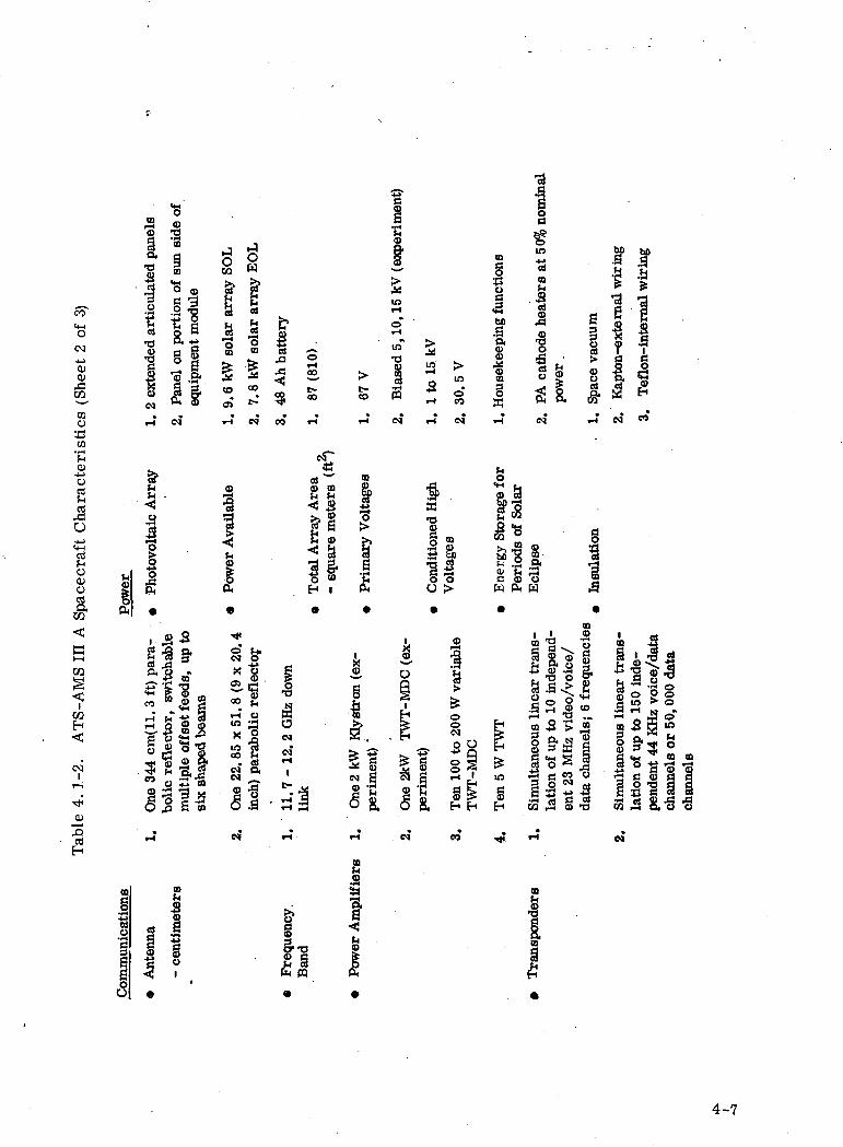
•a
o(N•4->
CD01
cnTOo
W
§ aa 3 t•3 ^ Sm ~ ~"m
ISca oO t-
CO 3 * oCO
s
asek
eepi
ng f
unct
ions
L cat
hode
hea
ters
at
51w
er .
ace
vacu
um
apto
n-ex
tern
al w
irin
g
'efl
on-i
nter
nal
wir
ing
CM CO J 'd «
CO
oS.ao•*-»=4-1
Socuoa
03
W
S<
GO
H
Ol
3rtH
h
.aI
Ph
. .2-3
CO
2 00
- S•< •§?8w O
itEH i
i•H-
Pri
mar
y V
o
fS
Con
ditio
ned
Vol
tage
s
<M
of
i>,i?01c
W
33Pe
riod
s of
£
§5-•3w In
sula
tion
•o
sc
§.2 2
s2 i s-sc m
wp
SSooI!•
!iI
OB
I
4-7

oo<4HO
oo-uo><uwtoo
CO•o
°.LO
i- i- eg
CO§ I
DObO
Coa s °=
13M
I
O •?}<B p.•5? S
.H <N CO
1
COen
HCO
ho
3 ">O rH
§ -H
cq
| §a «Sa
ofio i
V • fH
2 |s
oo>orto,
CO
COH
1 1
-a-s a 1°-.i .J8o c o a >+|5 +|5
M „
0)isPH
g,p
5
g<DtJ
I•I-H
&
rfer
omet
er
I•
|Ihigm§.ai•
•3
1
!1•
00
i§1g0
in
S»
FHSQQ
1
19f-i•o
*
18J2
¥i0o*-l
00•*esCO
><
limum
ca,H « CO ^
QJ I
fSII<^
!
Stat
io
3•3
4-8
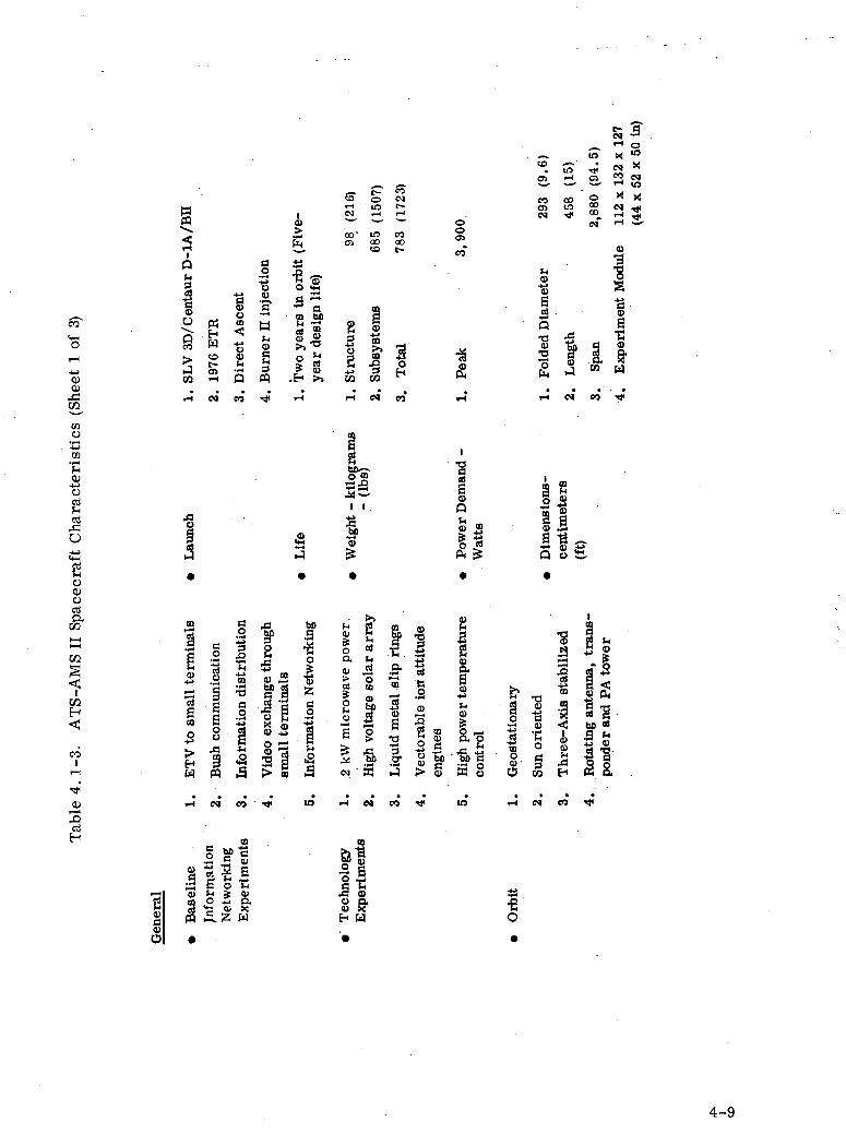
Q
IO
03
tfHWcoc-
§•8CD
•ff• J
1=1(H
Iw
o <£
5 aco bfisi> e*J §,
CD'cn
C-0in
ooto
coO)
COCOt-
ooenof
iH N
i
co
Ciu oj
g 8 1 04OJ •* «>_ r-l
tc
11.2Q
•8"O
S
fc3§.j
o•3
I•gID
Sa «
CQ H
COo
en
cu-aO
rt
O
o0)ort•&
raH
eo
-*OJ
^^5sM0)
CDO
• L
aunc
hE
TV
to
smal
l te
rmin
als
iH
1»— *0)
1•
o23
Bus
h co
mm
unic
atio
n
Info
rmat
ion
dist
ribu
tion
eg co
CDg to -g
rt 5 Sff o -Ct-i * O)o Z. o,
•a <u x•XS5 W
Vid
eo e
xcha
nge
thro
ugh
smal
l te
rmin
als
"*
Info
rmat
ion
Net
wor
king
•
su
i'^
2 kW
mic
row
ave
po
wer
.
Hig
h vo
ltag
e so
lar
arra
y
• •rt 04
CO
gl
llO p.« 5fH W
'•
Liq
uid
met
al s
lip
ring
s
Vec
tora
ble
ion
attit
ude
engi
nes
• •es TJ<
Dem
and
-•
Pow
erW
atts
Hig
h po
wer
tem
pera
ture
cont
rol
•in
Geo
stat
iona
ry
•tH
•yrt
o•
i.p.gisSu
n or
ient
ed
•04
s5<u
cent
imi
Thr
ee-A
xis
stab
iliz
ed
•
«
I
Rot
atin
g a
nte
nna,
tra
ns-
ponder
and
PA
tow
er
•
t
4-9
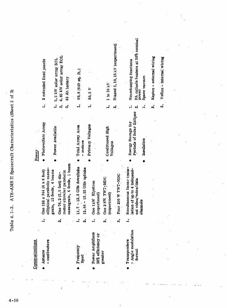
CO
•s<M
-*j>
cuo>
CQ
ID
1a"83T)WT3
0
1eg
AOco
&?•<S
S,— <
S1in
*us
OW
^5"
S•3m
1us•*•*
113.a
3O]•*
.
£
sro•*co
00
0>• CD
>
ino«
i-i eg co
.*: . ift
S •g
3 |^ «
m
1j0
1
Hou
seke
epin
g
in3oaP
1
PA c
atho
de h
epo
wer
Spa
ce v
acuu
m
a*
COI1a
!
a«>prff*%I-H•v^
1ao-3H
1 2 3
eno•fH^_>CO
73So<ti5-ini
U
ocuo03
co
f-lCOI
1iI
C1 co in<u co §QJ ffl 2
<M OJ S
00 O ^X! 5 ^
mCDbo
I
•S'"a
•S « « ?-a
eg cieg P
•i-* •»
U.2
aJ co
"M•s s- 8?m
25 g I* «O <O bO
JS a cdO c o
•a•o
I..2 co* SPIIO > In
sula
tion
04 eg CO
cati
ons
21o
4-10
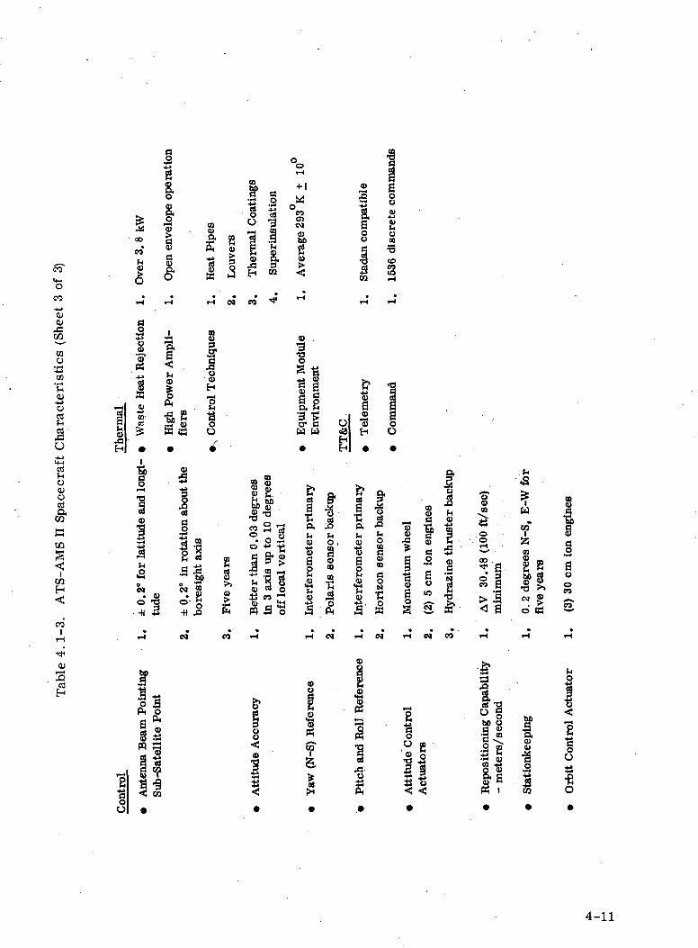
co
"8co-*-»QJ
g
&£"3
3 °8 IS
2*i 3 ®
I S s• « •
rH 0» CO
or-l
+ 1
CO05CM
1 1
*** 2
§• ^03 <
CDCO
W r-l
COo33CO
•c.sort
O
oQJOOS
RCQ
TOH
CO
O01
a
•a 2
DOcu
I• wEH
1O
4)
s a8 1s po. E•3 •?o- cH W
u>H
1
i-H
Q
•r*
3h5°C4
• <DO "O-H 5
.S•+J-U
cd
§
Itrf5|•t) .0
2S>>0)g
_ 00
S fi§>s,l -s-_ O rt
2rt S
Bet
ter
than
0.
in 3
axi
s up
toof
f loc
al v
erti
i r pr
imar
yIn
terf
erom
ete
1ti
Pol
aris
sen
so
r pr
imar
yIn
terf
erom
ete
§•
1ti
Hor
izon
sen
so
1
Mom
entu
m w
h
IDo>
«_o
ol»
S
a
1ha>1
Hyd
razi
ne
thr
f0)£o. orH
00 .* a.0 g« s>a< a
hO<y•fw
? '^(U P
§?8•S >>(M g
d a
000)
1au0CO
s
tH en
cu3cd
w
yu<ID
!
0)u
III
1u e® o1!si
at98'3 anC -s.
5^ilI?
0)<D
I
I
§O
•fiO
4-11
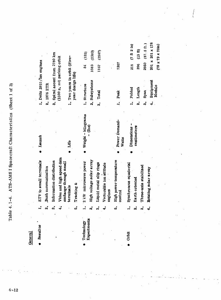
oo
•8
0)
CO
CQO
CO
o
O
0}
1be§
|\O
CftCM
•sQ-<•
Is •o ,0 ^QQ £4 ,*^
w 2) ^II i,•a § o «§*> o. a SS sr 5 fle IE. ifw « •« g,-e
• S § o SS Ui" £ 8•H co ^. H >>£>J CO i-I
oo
00
Str
uctu
re
t-J
DOfig
<«5
Si
CO00orS
CD
Sub
syst
em
ci
co10CM
t-cof-H
H•
CO
a
^ ^ CO
a •"' S S•3 **< 3CM g- m X g
t- d, 22- S «^^ e-tf><M 00 «O
«H 2CO «-lCO OCM CJ
Xen
1r-4 H
„ II§ fg«& ffa
QIH
S^
3 e§5
9 ^5 §
oOJoaen
en
enH
W 8
i0)
ICD
-4->
h<DZ
" ' 5 «! M2 I I If |lN a A > s a §
aH
eo P)
1
S3•fiO
4-12
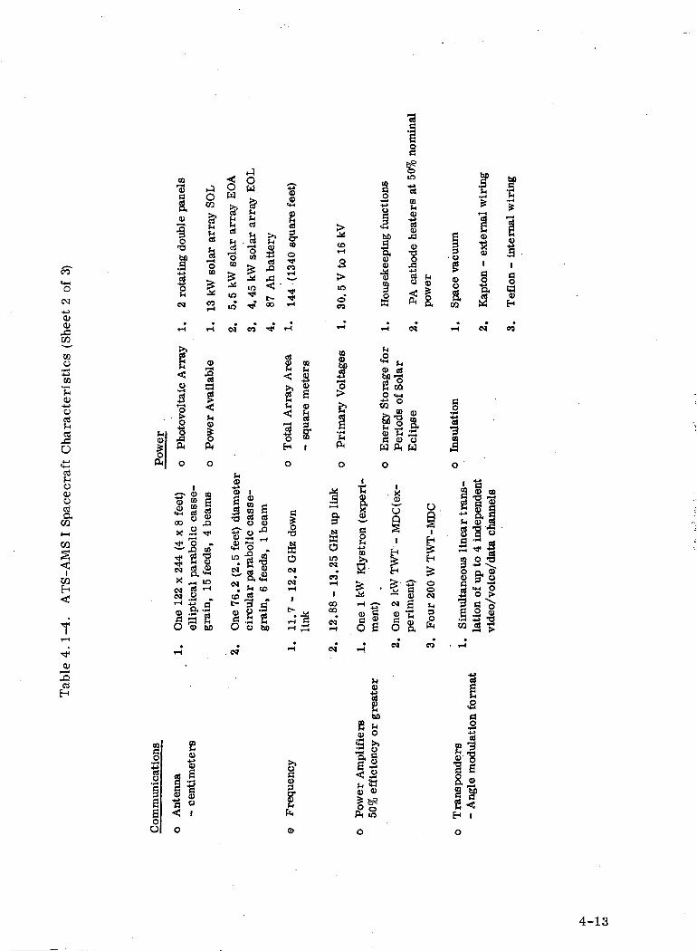
(M.*_>01<U
f
MO
•(—(-i-»
CO
•c0)
-4_>
ocdfHrt
O
Bo0)octia,
en
CQ
03H
t
h0>1ft
CD
1
fU
. 2 r
otat
ing
doub
l i
T-<
>>
H
<!o
Phot
ovol
tai
0
"8 COX to£ goo u
x aTji "g
'!N S.x "~ 1^ s<» .2-d ao 13•
r-l
JOens?231"o
CO
1COr-l
i-l
O••8a1M(D
10
beam
s
•*oTT3s^Mini-l
a"abO
^W
c^fjsa•sCO
1inin
C4
HsI.3•alifOJV
<M
in•
CM• fCM
•tot-0)
<§•
. CM
_!
0U
&(-1poH >»ra ^i
1 |
£ *•^ 5!-TjT oo
CO •*
cass
e-ea
m
0 -°
^1•S "oS"8a«2^ to
|.a.§ au be
?5
1o•COr-<
•*•*iH
f-t
fl) CQH Cd
< «
^> 0)
Tot
al A
rra;
- sq
uare
m
o
a
1SOCM
•CMrH
J
t> j.
iH B-1 S
••H
^<£>r-l
S>in
»oCO
*T-t
CO0)hntf-2"o
Pri
mar
y V
o
|
i1
SffiOinCM
•
COI-l1
oooo
•
CMrH
•CM
ictlo
ns
y
Hou
seke
epin
g fu
r-(
(-1
<2 h0> cdSP1?2 CQ
Ene
rgy
Sto:
Per
iods
of
0
1 •*5? 0
X* ^J
1m H
fr 8ss -a^ i" N0> G ®as <sH N'
•a
1in•3COWQ
PA c
atho
de h
eapo
wer
CM
IDa-F-4
Uw
O ,
i
H£
S3- oC 0V CM
6 -H•c E8, £
•CO
. Sp
ace
vacu
um
i-i
Insu
latio
no
Sa•+jMsa
i— *
9o(Da
1•p4
CQ
•* iH
«^i£
«1
I3CM
a> m"S "9 3<D eg"So
of u
p to
4 i:
voic
e/da
ta
8111
i-*
£P-H
. T
eflo
n -
inte
rns
CO
rt
bO
g0)
0) <D
|^ft in
o
4-13
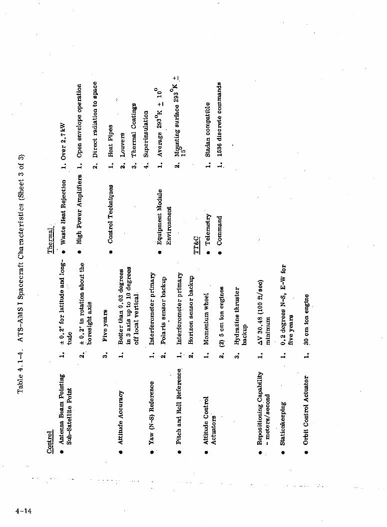
+ 1
oCQ
eno
CO
O)•4^o
O
BocuortC&
en
?COH<
CD
IH
co"t-i
I~ .
|+j0
•5*5
ai *to1
• •
1
rt .
10CO
• 0)*!rH
05•gf aa*Ss«§1 •?13< m
; ope
ratio
n
on to
spa
ce
cv ^-»
o S•3 T3
1 SCS Q)
O Q
r-t e*
o>«r^5I^1
f•
1
. ±
0. 2
' in
rot
atio
n ab
out
bore
sigh
t ax
is
OJ
m&S
"S
rH
835
8EH
S1•
E1CD
CO
' f
1oB 1co c§ S3 43
H
CO CO
m
| Is,g>Q) *ri
« < = -"^ rH f*4o 5• O .F*
0 •" -g
o §• SSI r»£ ffl _
* "S «±5 co rt
rH
tude
Acc
urac
y
••4
c
a*-H M
rins
ulat
icIDa3
*
, In
terf
erom
eter
pri
mar
y
rH
Q>O
i (N
-S)
Ref
eren
s
So c
rH
+ 1
3CO05CO
IDbfi
ID
5^
1r! "g
1 |
S s5 1>o- aH H
.
. P
ola
ris
sens
or b
acku
p
c*
coa>CO
IDO
3mbo
•«->
|°*S rH
M
Inte
rfer
omet
er p
rim
ary
rH
<D
§
2M
i•srtO
S
o°3H
Hor
izon
sen
sor
back
up
0»
<oa+j
!o0
irH
t
1<0-sH
, M
omen
tum
whe
el
1-1
tude
Con
trol
•r*t
0>
s0o0)10
cocorH
rH .
* 1?
0u
, (2
) 5
cm i
on e
ngin
es
, H
ydra
zine
th
rust
erba
ckup
OJ CO
eo1
, A
V 3
0.48
(10
0 ft/
sec)
min
imum
rH
§
2
osit
ioni
ng C
apa
eter
s/se
cond
8- a
t-i«2*W
Hof SJ2J "MID §
22 gg1 S ""•a >> 8M ® ^. > 0o 53 co.
rH rH
(4o
ionk
eepi
ng
it C
ontr
ol A
ctui
I S
4-14
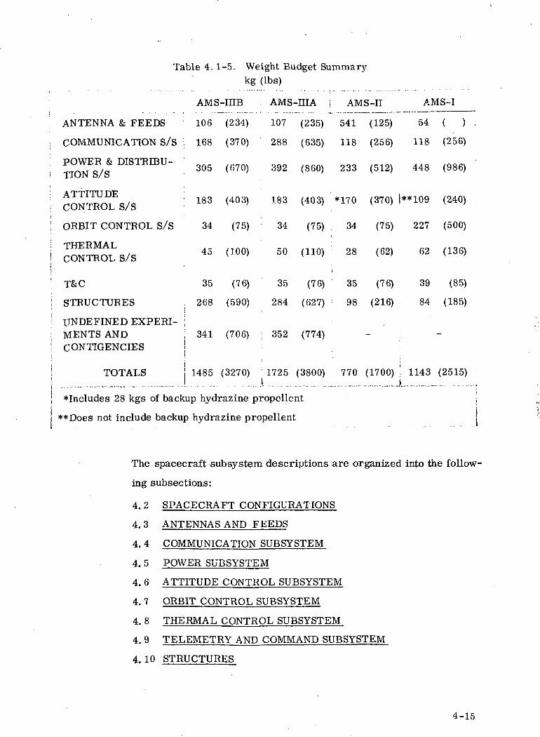
Table 4.1-5. Weight Budget Summarykg (Ibs)
ANTENNA & FEEDS
COMMUNICATION S/S
POWEE & DISTRIBU-TION S/S
ATTITUDECONTROL S/S
ORBIT CONTROL S/S
THERMALCONTROL S/S
T&C
STRUCTURES
AMS-IHB
106 (234)
168 (370)
305 (670)
183 (403)
34 (75)
45 (100)
35 (76)
268 (590)
UNDEFINED EXPERI- :MENTS AND j 341 (706)CONTIGENCIES |
TOTALS
AMS-HIA j AMS-II AMS-I
107 (235) 541 (125) 54 ( )
288 (635) 118 (256) 118 (256)
392 (860) 233 (512) 448 (986)
183 (403) *170 (370) |**109 (240)
34 (75) 34 (75) 227 (500)
50 (110) ; 28 (62) 62 (136)
35 (78) ; 35 (76)
284 (627) : 98 (216)
352 (774)
39 (85)
84 (185)
1485 (3270) 1725 (3800) 770 (1700) j 1143 (2515)
*Includes 28 kgs of backup hydrazine propellent
**Does not include backup hydrazine propellent
The spacecraft subsystem descriptions are organized into the follow-
ing subsections:
4.2 SPACECRAFT CONFIGURATIONS
4.3 ANTENNAS AND FEEDS
4.4 COMMUNICATION SUBSYSTEM
4.5 POWER SUBSYSTEM
4.6 ATTITUDE CONTROL SUBSYSTEM
4.7 ORBIT CONTROL SUBSYSTEM
4.8 THERMAL CONTROL SUBSYSTEM
4.9 TELEMETRY AND COMMAND SUBSYSTEM
4.10 STRUCTURES
4-15

4.2 SPACECRAFT CONFIGURATION
4.2.1 GENERAL DESCRIPTION - ATS-AMS HI
The ATS-AMS HI- A consists of a cube shaped equipment module having
a rotatable platform on its forward face, a cluster of three 30 cm ion
engines on its aft face and extendable body fixed solar panels on the
two faces which are normally parallel to the orbit plane. The space-
craft is attached to the Titan UIC by an adapter section of four sets of
tubular trusses. These trusses will contain provisions for guiding the
spacecraft during separation from the booster. The concept shown is
similar to the system used on ATS-F. The spacecraft is 660.2 cm
(256.0 inch) high and will fit into a 274.32 cm (108 inch) diameter pay-
load envelope. A sketch of the spacecraft is shown in Figure 1. 3. 2-1
and an overall layout is presented in Figure 40 2- 1.
4.2.1.1 Equipment Module
The equipment module cube measures 17708 cm (7000 inches) along
all edges. The internal structure is a tubular center section which
contains four fittings for attaching the spacecraft to the adapter sections.
The upper and lower sections consists of extruded angle framework
with machined fittings at the corners0 The top section of the module
contains a cylindrical section which houses the bearings and the
cylindrical portion of the rotating platform support structure. This
support structure consists of an outer channel ring section which is
attached to the cylindrical portion by a series of tapered bulkheads.
This structure will als o contain provisions for securing the rotating
platform during launch. Attached to the center section structure and
extanding into the lower module section is a tubular framework which
is provided for attaching one or three 30 cm ion engines. The outside of
the module will be covered with honeycomb sandwich panels „ Several
of these panels will be removable for equipment access. Although it
is anticipated that for thermal reasons, the majority of the equipment
4-16
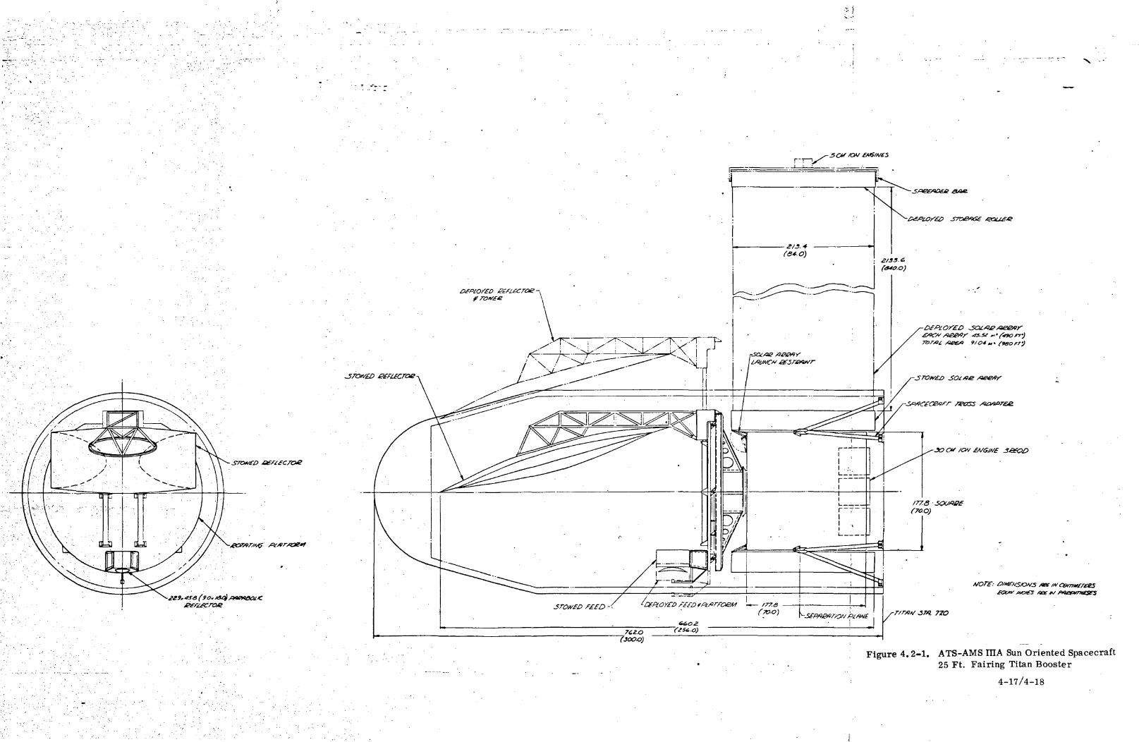
••• 1
Figure 4.2-1. ATS-AMS IIIA Sun Oriented Spacecraft25 Ft. Fairing Titan Booster
4-17/4-18

will be mounted to the module side panels additional shelves could be
added to the upper and lower side of the center section structure.
See Figure 4.2-2.
402.1.2 Rotating Platform
The rotating platform consists of a reinforced honeycomb panel which
contains all of the communication equipment. The platform is secured
to the support structure during launch by a series of shear fittings and
explosive devices. Auxiliary framework structure to support super
insulation blankets can be added to the platform to thermally control
the electronic equipment. Also attached to this platform are the main
antenna feeds. The reflector and its supporting tower are attached to
the support structure through shear fittings and explosive release
devices. The 344.42 cm (135. 6 inch) diameter parabolic reflector is
constructed of honeycomb panels supported on radial ribs. The tower
is a welded tubular truss with outrigger structure near the top to pro-
vide a1 mounting surface for the antenna,, Once the spacecraft is in
orbit, the reflector and tower are deployed outward 110.49 cm (43.5
inches) through a telescopic tubing arrangement. The platform with
the feed package and the communication equipment is then deployed in
the opposite direction approximately 20.32 cm (8.0 inches). The
reason for the deployment of both sections is twofold: first to achieve
the proper focus between the feed and the reflector and second to main-
tain proper balance of the spacecraft. It is anticipated that a motor
driven screw jack will be used to drive both the platform and the
reflector and tower to their deployed positions. A similar mechanism
will be used to tilt the platform thereby accurately aligning the antenna -
if required.
4.2.1.3 Solar Arrays
The details of the solar array design are presented in Section 4.5. A
basic design goal was not to exceed a 10 to 1 aspect ratio of length to
width of the array. Each of the two arrays are 213.4 cm (84.0 incheso
wide by 2133.6 cm (840. 0 inches long) and provide for 45.52 m
4-19/4-20

Figure 4. 2-2. Equipment Module StructureATS-AMS HI
4-21/4-22

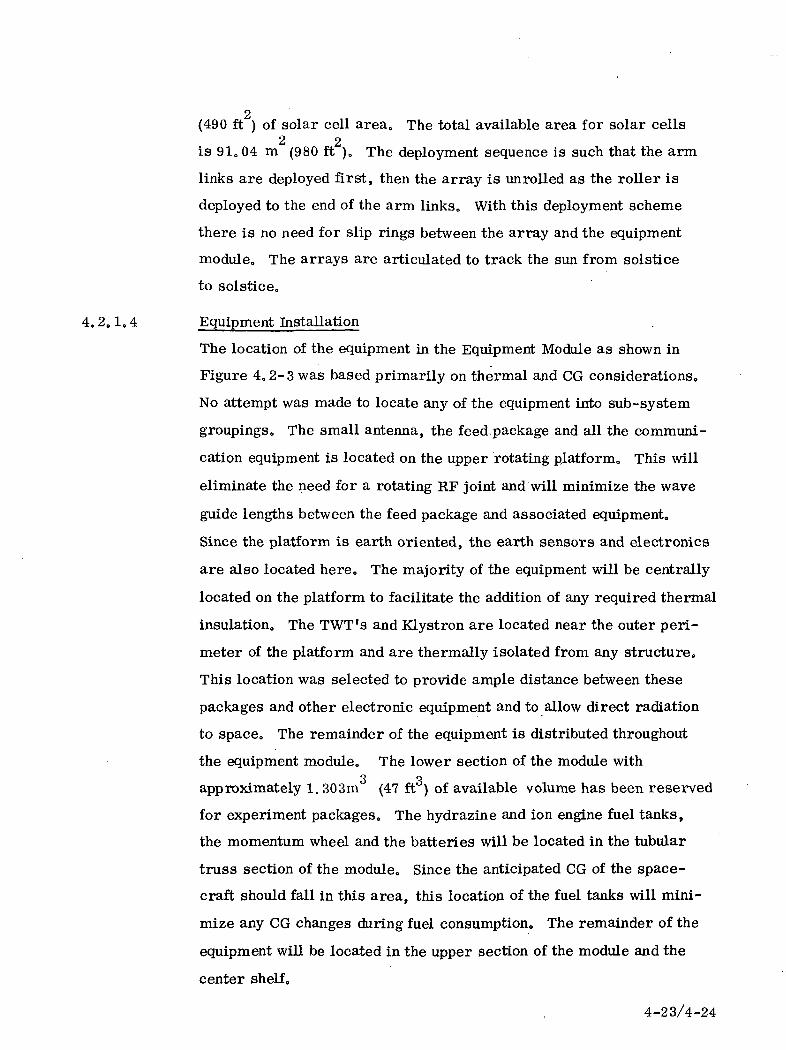
2(490 ft ) of solar cell area. The total available area for solar cells
2 2is 91004 m (980 ft )„ The deployment sequence is such that the arm
links are deployed first, then the array is unrolled as the roller is
deployed to the end of the arm links. With this deployment scheme
there is no need for slip rings between the array and the equipment
module. The arrays are articulated to track the sun from solstice
to solstice,,
4.2.1,4 Equipment Installation
The location of the equipment in the Equipment Module as shown in
Figure 4.2-3 was based primarily on thermal and CG considerations.
No attempt was made to locate any of the equipment into sub-system
groupings. The small antenna, the feed.package and all the communi-
cation equipment is located on the upper rotating platform. This will
eliminate the need for a rotating RF joint and will minimize the wave
guide lengths between the feed package and associated equipment.
Since the platform is earth oriented, the earth sensors and electronics
are also located here. The majority of the equipment will be centrally
located on the platform to facilitate the addition of any required thermal
insulation. The TWT's and Klystron are located near the outer perl-
meter of the platform and are thermally isolated from any structure.
This location was selected to provide ample distance between these
packages and other electronic equipment and to allow direct radiation
to space. The remainder of the equipment is distributed throughout
the equipment module. The lower section of the module with3 3approximately 1. 303m (47 ft ) of available volume has been reserved
for experiment packages. The hydrazine and ion engine fuel tanks,
the momentum wheel and the batteries will be located in the tubular
truss section of the module. Since the anticipated CG of the space-
craft should fall in this area, this location of the fuel tanks will mini-
mize any CG changes during fuel consumption. The remainder of the
equipment will be located in the upper section of the module and the
center shelf.
4-23/4-24

rI 1
i! II I
@fll
11 1 —1 1prxj;
i,\vj
— ir~i1 1
it>'®i — 11—-—-! ll
L
'H
i :! 'i /•
ITEM MOMEMC'-ifUGJ ! SIZE :M CM''
A £ : &'.-< Ii :'• S i'-r'-i. Si- -> •' I. -2 =T. '.! S.!«l.il7 OIA.
6 ; l-=;o P^fe S I 2SO
e> 5 i pscc «.''/_'-'^~<D^
B 7E.a ir-"
ci i-:C2 h
'25.4 O'&'55 5'At. DlA. t=c.g pop O>A » 22.025-4 CA '<!5.~2TiOOC'A •• .3.03.o) IS.08 Pi16.Id x 1S.4c\ io.SC^.S. 10.O.L4.0)!
31.30 Q?.o«13..tj
• 5.08-767 6.Q- 2.0.3.0)I5J.-7.G2 «io. it QC-
C 3 .P ic.5 OKk * ~.O)C A I
iic=../;: JD
'•2.54. "7.42 « IP. l_C7
2 I2 I
D ^ i i^TI^r^^ -Z«': 17.3* 73^15.73 :' .C-7^3.Q7^-o ;S3j ; ^D 5 i'^AJT
D a :^ (
-C'J_J
I -1
Figure 4. 2-3. ATS-AMS III A Sun OrientedSpacecraft Equipment Layout
4-25/4-26
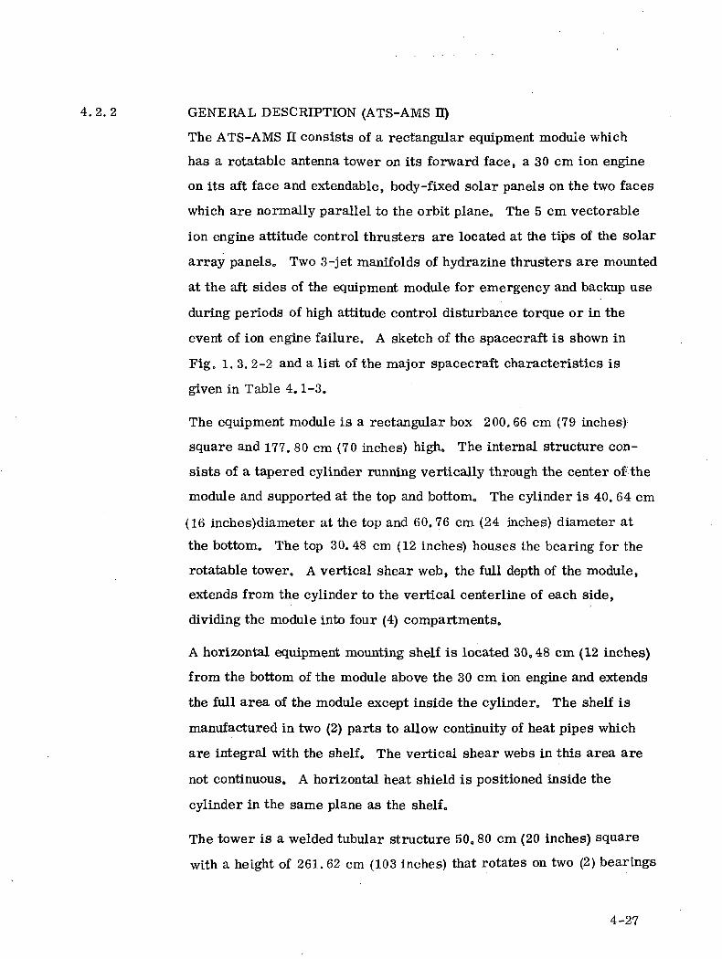
4.2.2 GENERAL DESCRIPTION (ATS-AMS II)
The ATS-AMS n consists of a rectangular equipment module which
has a rotatable antenna tower on its forward face, a 30 cm ion engine
on its aft face and extendable, body-fixed solar panels on the two faces
which are normally parallel to the orbit plane. The 5 cm vectorable
ion engine attitude control thrusters are located at the tips of the solar
array panels. Two 3-jet manifolds of hydrazine thrusters are mounted
at the aft sides of the equipment module for emergency and backup use
during periods of high attitude control disturbance torque or in the
event of ion engine failure. A sketch of the spacecraft is shown in
Fig. 1. 3. 2-2 and a list of the major spacecraft characteristics is
given in Table 4.1-3.
The equipment module is a rectangular box 200.66 cm (79 inches)
square and 177. 80 cm (70 inches) high. The internal structure con-
sists of a tapered cylinder running vertically through the center of the
module and supported at the top and bottom. The cylinder is 40. 64 cm
(16 inches)diameter at the top and 60.76 cm (24 inches) diameter at
the bottom. The top 30. 48 cm (12 inches) houses the bearing for the
rotatable tower. A vertical shear web, the full depth of the module,
extends from the cylinder to the vertical centerline of each side,
dividing the module into four (4) compartments.
A horizontal equipment mounting shelf is located 30.48 cm (12 inches)
from the bottom of the module above the 30 cm ion engine and extends
the full area of the module except inside the cylinder. The shelf is
manufactured in two (2) parts to allow continuity of heat pipes which
are integral with the shelf. The vertical shear webs in this area are
not continuous. A horizontal heat shield is positioned inside the
cylinder in the same plane as the shelf.
The tower is a welded tubular structure 50. 80 cm (20 inches) square
with a height of 261. 62 cm (103 inches) that rotates on two (2) bearings
4-27
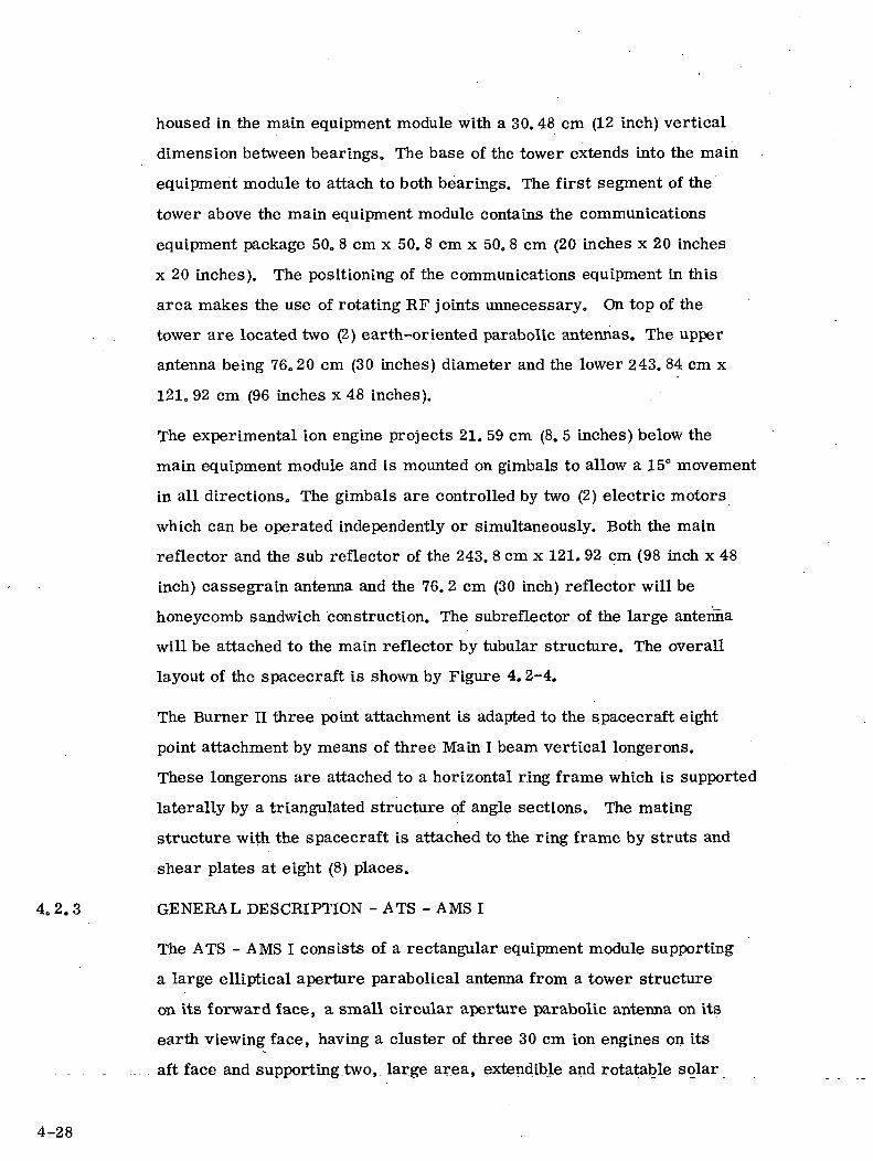
housed in the main equipment module with a 30. 48 cm (12 inch) vertical
dimension between bearings. The base of the tower extends into the main
equipment module to attach to both bearings. The first segment of the
tower above the main equipment module contains the communications
equipment package 50. 8 cm x 50. 8 em x 500 8 cm (20 inches x 20 inches
x 20 inches). The positioning of the communications equipment in this
area makes the use of rotating RF joints unnecessary. On top of the
tower are located two (2) earth-oriented parabolic antennas. The upper
antenna being 76.20 cm (30 inches) diameter and the lower 243. 84 cm x
121. 92 cm (96 inches x 48 inches).
The experimental ion engine projects 21. 59 cm (8. 5 inches) below the
main equipment module and is mounted on gimbals to allow a 15° movement
in all directions. The gimbals are controlled by two (2) electric motors
which can be operated independently or simultaneously. Both the main
reflector and the sub reflector of the 243. 8 cm x 121. 92 cm (98 inch x 48
inch) cassegrain antenna and the 76. 2 cm (30 inch) reflector will be
honeycomb sandwich construction. The subreflector of the large antenna
will be attached to the main reflector by tubular structure. The overall
layout of the spacecraft is shown by Figure 4.2-4.
The Burner II three point attachment is adapted to the spacecraft eight
point attachment by means of three Main I beam vertical longerons.
These longerons are attached to a horizontal ring frame which is supported
laterally by a triangulated structure of angle sections. The mating
structure with the spacecraft is attached to the ring frame by struts and
shear plates at eight (8) places.
4.2. 3 GENERAL DESCRIPTION - ATS - AMS I
The ATS - AMS I consists of a rectangular equipment module supporting
a large elliptical aperture parabolical antenna from a tower structure
on its forward face, a small circular aperture parabolic antenna on its
earth viewing face, having a cluster of three 30 cm ion engines on its
. . . . . . „_. aft face and supporting two, large area, extendible and rotatable solar
4-28
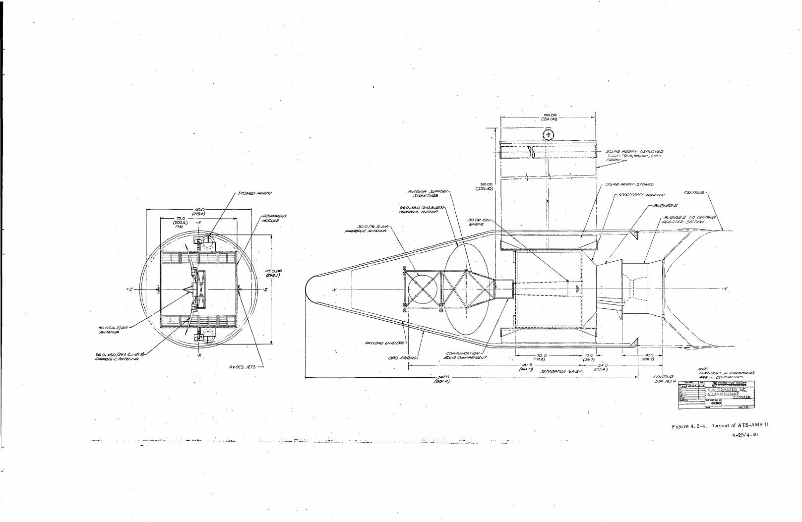
a toes JETS •
faa/-<t) .•., >-
=s^ 1
•~,.,.0~.ID _,.!.-
5dM OS\E.NTED 5/t
| 66360
' OSIEU:
Figure 4. 2-4. Layout of ATS-AMS II
4-29/4-30
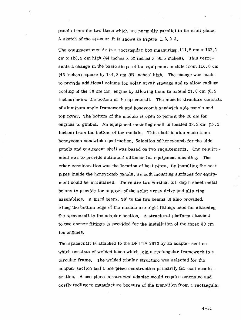
panels from the two faces which are normally parallel to its orbit plane.
A sketch of the spacecraft is shown in Figure 1. 3. 2-3.
The equipment module is a rectangular box measuring 111. 8 cm x 132.1
cm x 128.3 cm high (44 inches x 52 inches x 50.5 inches). This repre-
sents a change in the basic shape of the equipment module from 116. 8 cm
(45 inches) square by 1440 8 cm (57 inches) high. The change was made
to provide additional volume for solar array stowage and to allow radiant
cooling of the 30 cm ion engine by allowing them to extend 21. 6 cm (8. 5
inches) below the bottom of the spacecraft. The module structure consists
of aluminum angle framework and honeycomb sandwich side panels and
top cover. The bottom of the module is open to permit the 30 cm ion
engines to gimbal. An equipment mounting shelf is located 33. 3 cm (13.1
inches) from the bottom of the module. This shelf is also made from
honeycomb sandwich construction. Selection of honeycomb for the side
panels and equipment shelf was based on two requirements. One require-
ment was to provide sufficient stiffness for equipment mounting. The
other consideration was the location of heat pipes. By installing the heat
pipes inside the honeycomb panels, smooth mounting surfaces for equip-
ment could be maintained. There are two vertical full depth sheet metal
beams to provide for support of the solar array drive and slip ring
assemblies, A third beam, 90° to the two beams is also provided.
Along the bottom edge of the module are eight fittings used for attaching
the spacecraft to the adapter section. A structural platform attached
to two corner fittings is provided for the installation of the three 30 cm
ion engines.
The spacecraft is attached to the DELTA 2910 by an adapter section
which consists of welded tubes which join a rectangular framework to a
circular frame. The welded tubular structure was selected for the
adapter section and a one piece construction primarily for cost consid-
eration. A one piece constructed adapter would require extensive and
costly tooling to manufacture because of the transition from a rectangular
4-31
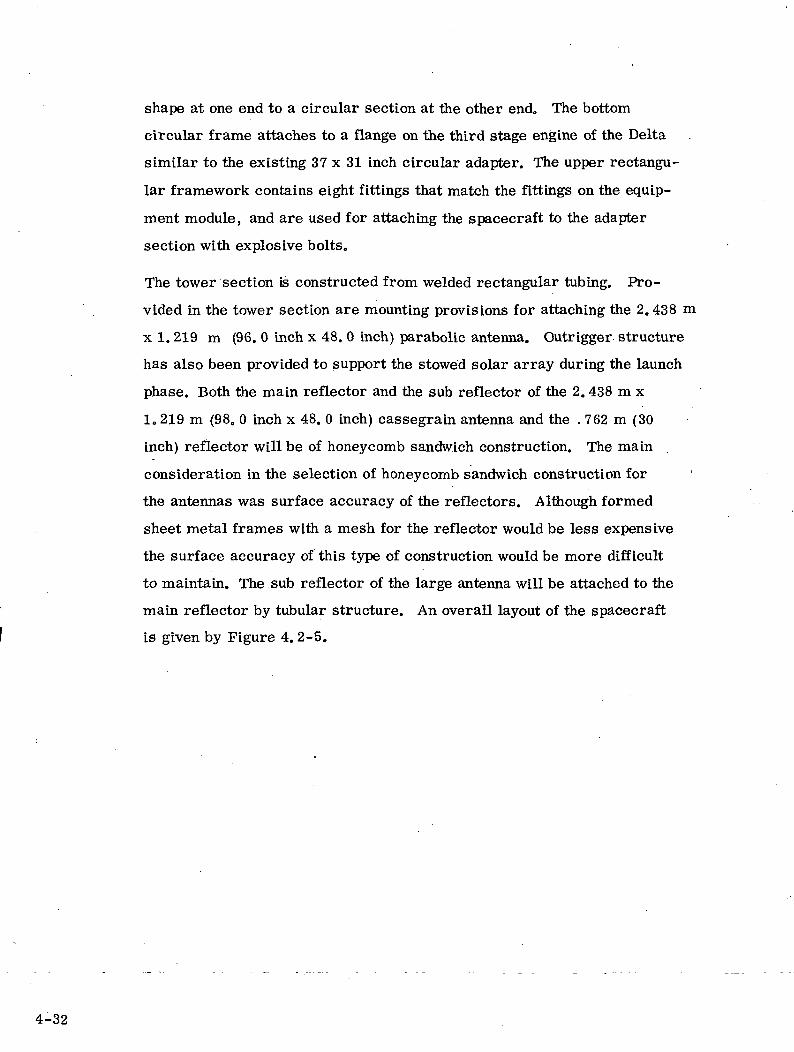
shape at one end to a circular sectLon at the other end. The bottom
circular frame attaches to a flange on the third stage engine of the Delta
similar to the existing 37 x 31 inch circular adapter. The upper rectangu-
lar framework contains eight fittings that match the fittings on the equip-
ment module, and are used for attaching the spacecraft to the adapter
section with explosive bolts.
The tower section is constructed from welded rectangular tubing. Pro-
vided in the tower section are mounting provisions for attaching the 2.438 m
x 1. 219 m (96. 0 inch x 48. 0 inch) parabolic antenna. Outrigger structure
has also been provided to support the stowed solar array during the launch
phase. Both the main reflector and the sub reflector of the 2. 438 m x
1.219 m (98. 0 inch x 48. 0 inch) cassegrain antenna and the . 762 m (30
inch) reflector will be of honeycomb sandwich construction. The main
consideration in the selection of honeycomb sandwich construction for
the antennas was surface accuracy of the reflectors. Although formed
sheet metal frames with a mesh for the reflector would be less expensive
the surface accuracy of this type of construction would be more difficult
to maintain. The sub reflector of the large antenna will be attached to the
main reflector by tubular structure. An overall layout of the spacecraft
is given by Figure 4. 2-5.
4-32
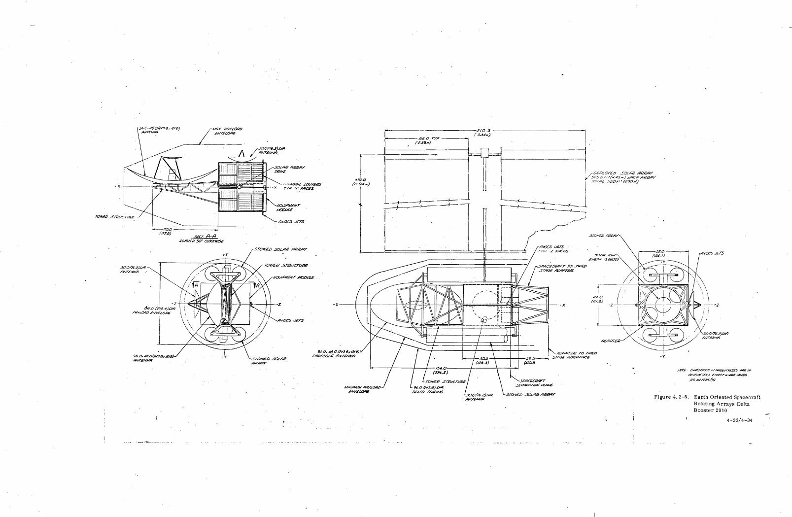
•f/rocs J£FS
Figure 4.2-5. Earth Oriented SpacecraftRotating Arrays DeltaBooster 2910
4-33/4-34
4.3 ANTENNAS AND FEEDS
4. 3.1 ATS-AMS HI ANTENNAS
4,3.1.1 Coverage
The Public Broadcasting System Networking experiments require
individual coverage of the four CONUS time zones in addition to
Alaska and Hawaii, in order to distribute television programs
throughout each of these zones. Signal separation between zones
is an essential part of the experiment, so as to permit frequency
re-use without interference from one zone to another. Part of
this separation is achieved by contouring with multiple narrow-
beamwidth beams. Figure 4.3.1-1 shows in heavy lines the
3 dB contour for the PBS experiment for ATS-AMS IIIA. The
dashed lines show the reduced coverage of ATS-AMS IIIB. The
various channels distributed throughout each zone of ATS-
AMS IIIB are symbolized on Figure 4.3.1-1 as "f , f ," etc.A. -D
The same channels that are received in Alaska are also dis-
tributed to Hawaii by means of a 1/2 beam.
Deviations between the shown coverages and the actual time
zones are due to physical constraints in positioning adjacent
multiple feeds. To obtain overlap of adjacent patterns would
require an additional large antenna, which was not felt to be
justified since the 3 dB coverage can be supplemented by
stations outside the contours shown with a higher gain facility.
These patterns are obtained from a satellite position of 110
west longitude, which provides a particularly excellent coverage
of the more heavily populated Southeastern area of Alaska, as
shown in heavy lines in Figure 4.3.1-2, without excessive
spillover into Canada. Positioning the satellite at a point
further west increases spillover into Canada and does not
4-35

•*0>f-t3be
4-36
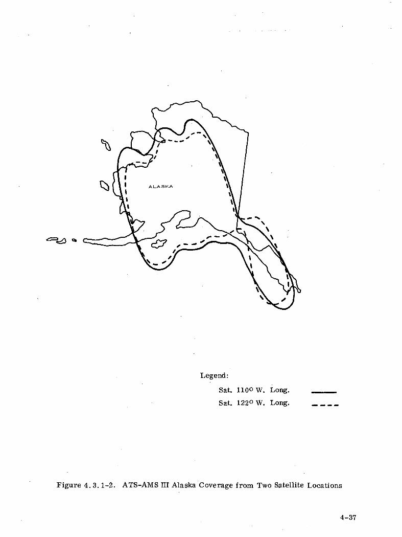
Legend:
Sat. 110° W. Long.
Sat. 122« W. Long.
Figure 4. 3.1-2. ATS-AMS HI Alaska Coverage from Two Satellite Locations
4-37
improve coverage of Alaska, in addition to a poorer CONUS
coverage. Figure 4.3.1-2 shows in dotted lines the Alaska cover-
age from a satellite location of 122 west longitude.
The Cultural Region Interactive Television (ITV) experiments
will be carried out with the same antenna used for the PBS experi-
ment, and the desired coverage is achieved by re-assigning the
necessary feeds so as to follow as close as possible the ITV
regional boundaries. As shown in Figure 4.3.1-3, coverage
of the six cultural regions is achieved with very little overlap
into neighboring regions. The main restriction is the position
that the feeds have been assigned for the PBS experiment. How-
ever, the amount of switching required to accomplish this trans-
fer from time-zone coverage to cultural-region coverage is
reasonable in weight and complexity. The re-assignment of
feeds is the basic method to be employed in obtaining the desired
coverages. Additional adjustments in the position of the feeds
may improve the final coverages for the various experiments.
In addition, coverage of Alaska is proposed for ATS-AMS IIIB,
for medical communications.
Reception of video will be carried out by only those feeds that are
directed to the areas containing originating stations. Therefore,
satellite reception will be through 1/2 beams, relaxing the power
requirements of the ground transmitters and, indirectly, the
coordination constraints on earth station sites. For ATS-AMS IIIB,
Alaska reception can be switched to any of the feeds that cover
that region, for medical communications.
4.3.1.2 Large Reflector
Figure 4.3.1-4 shows the 3.44 meter (11.3 feet) parabolic offset
reflector with the feed matrix at a focal length of 3.1 meters. This
corresponds to.the relatively large f/D ratio of 0.9, which minimizes
4-38
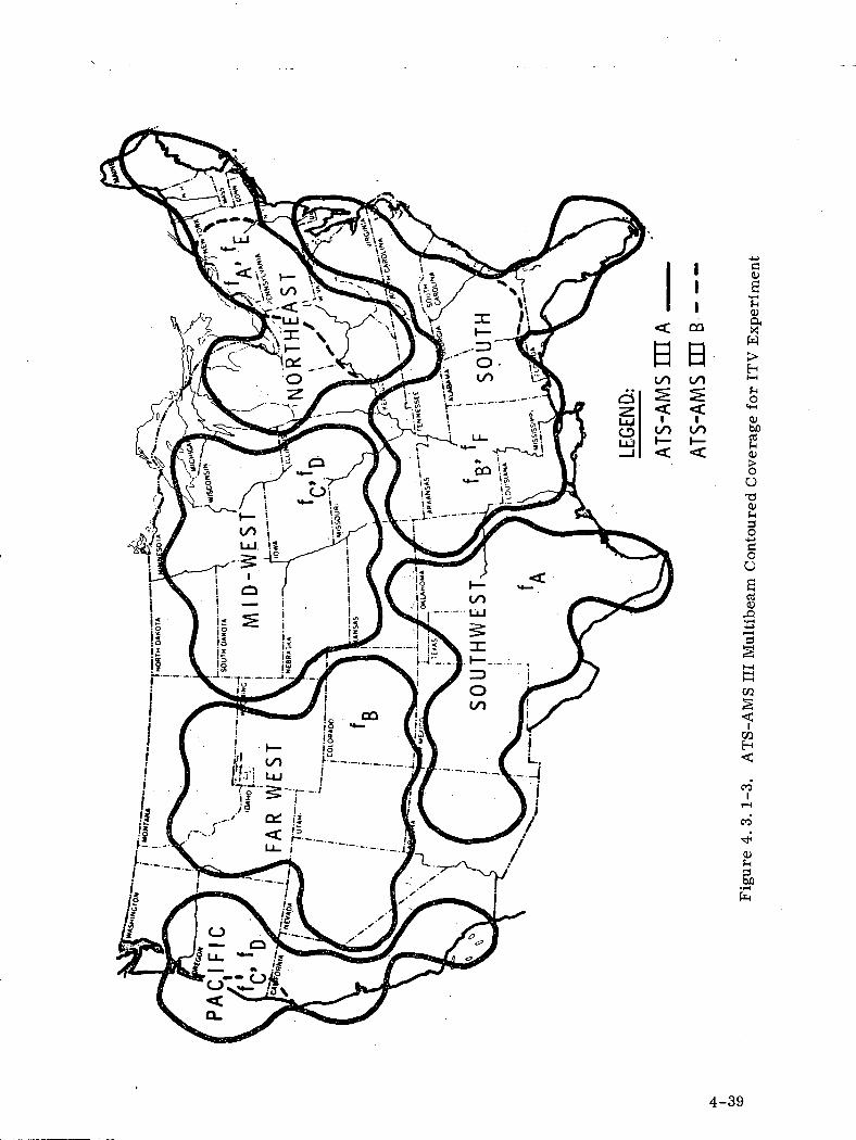
<
0
111
en
a-
ao>S'C0)
*H>H
GO LO
S ^< <
CO LO01bert
0TJO)^§•u
OU
art01
aCO
05H
CO
r-l
CO
-*'
01
4-39
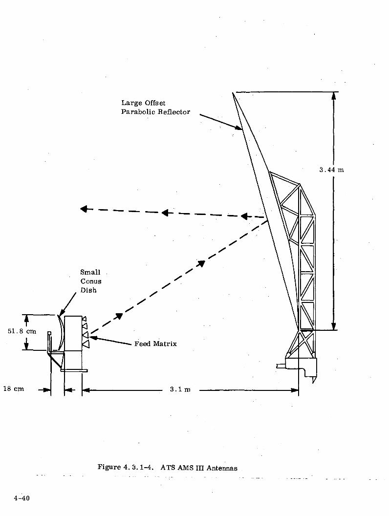
Large OffsetParabolic Reflector
3.44 m
18 cm
Figure 4. 3.1-4. ATS AMS III Antennas
4-40

the comatic aberrations inherent in scanning. As shown in
Table 4. 3.1-1 the reflector and its supporting structure are estimated
to weigh 45 kg (100 Ibs), and are deployed approximately 1. 3 m (4. 16 f t . )
back from their position at launch.
4.3.1.3 Feed Matrix
A total 37 of the 39 feeds are required for PBS coverage of CONUS, Alaska
and Hawaii. The number of feeds assigned to each region is
shown in Table 4.3.1-1. The position of the feeds is shown in
Figure 4.3.1-5. However, adjustments are expected to be
required in compromising the final coverage desired. The feeds
are waveguide-fed horns flared in both planes to achieve tapering
of the reflector illumination. The dimensions of each feed are
3.64 cm x 3. 64 cm (1. 43 x 1. 43 in) and the total feed matrix is expected to
exceed 20 x 50 cm (7.9 x 19.7 in) in size.
Some switching is required in order to re-assign transmitter and
feeds from one experiment to the next. However, not all the
feeds and transmitters have to be re-assigned between experiments,
since many are common to several experiments. The complete
switching system requires circulators, switches, and hybrids;
Table 4.3.1-2 shows the approximate weight of all these components,
which total 106 kg (235 Ibs), including feeds and waveguides.
Selected feeds have orthogonal ports to which the receivers are
connected, permitting full utilization of polarization for transmitter-
to-receiver isolation in the satellite transponder. Additional
isolation of transmitter power at the receiver is achieved by
inserting a short strip of waveguide at the front end of the receiver,
which filters the transmitter power by acting beyond cut-off at the
12 GHz transmitter frequencies.
4-41
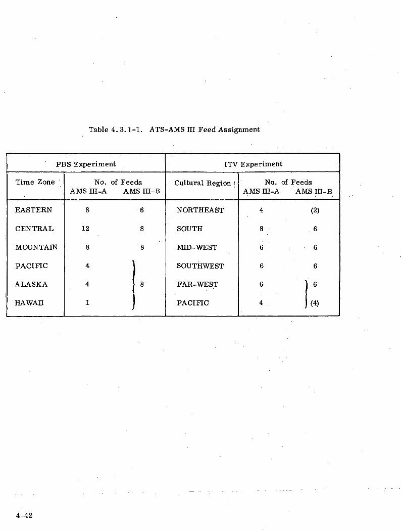
Table 4. 3.1-1. ATS-AMS HI Feed Assignment
PBS Experiment
Time Zone '
EASTERN
CENTRAL
MOUNTAIN
PACIFIC
ALASKA
HAWAII
No. of FeedsAMS III-A AMS IH-B
8 6
12 8
8 8
4
4
1
8
ITV Experiment
Cultural Region <
NORTHEAST
SOUTH
MID- WEST
SOUTHWEST
FAR-WEST
PACIFIC
No. of FeedsAMS ni-A AMS IH-B
4 (2)
8 6
6 6
6 6
6 ] 6
4 j (4)
4-42

CJ
00
W>-)<O
ort
-o0101
01ocoo
en
Kl
co
^-
0)^HsbD
4-43
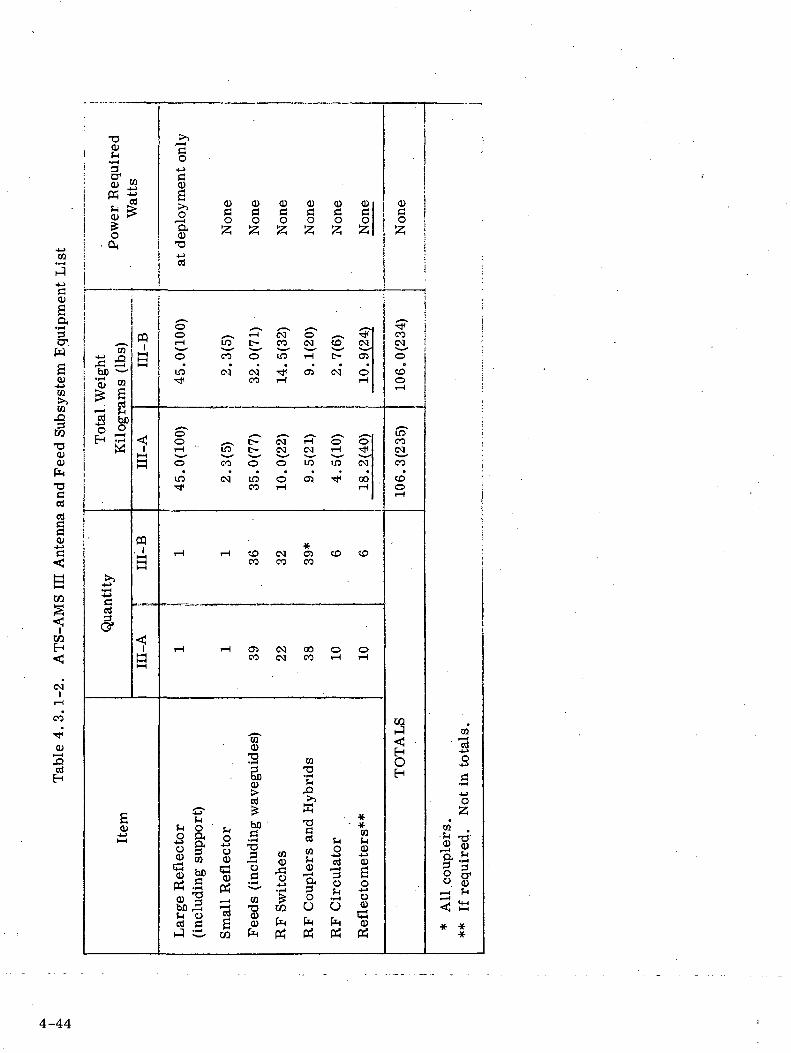
03
CD
3CT
S01
•4->CQ>>CQ
•aa>a>
T3Cen
B
S<
<
i-H•
co
0
I
•o<u
^! 'sQi) '
to SCO "
O
CQ
bo ;:::'°OJ CO
£ Srt
m ^.2 bo0 0r i ^^
W
'
§a
a.s
0
^
>
PQ
B
^^HH
B
PQ. ih-HI-H
1
BhH
"O^_>g0
* QJ Q? QJ Q) QJ Q)0 C (3 (3 C C! C
,-H O O O O O OQ2 f-\ £-\ £-\ f-i f-\ £-*
I
o ^ ^ cT o^ *-. ^1iH in C- CO <N CD CM
o co o m IH t- osin c-3 csi f cs CNI oTt* CO i— 1 iH
O ^-, t- (M rH o Oi-i" m t- esj cq i-i ^o co o o m m c>qin CM m o us •* oo• CO iH T-l
*iH iH CO (N <3> CD COco co co
iH iH O5 CM 00 O OCO CM CO iH iH
0
2 ^0 to
> *£rt >>
^ M- S ' J
1 I o -2 § h " g
lilliH!< B ^ _ J C Q ^ Q Q S
r t a a 0 ^ 1 ^ ^ 0^ ^ C Q ^ t i t f P H
0o!z;
coss
o
CD0I— I
in"COCM
co*co'0i-i
CQ
1'H
CQ
3a^^oZ,
* A
ll co
uple
rs*
If r
equired.
*
4-44
4.3.1.4 Small Reflector
A small parabolic dish of dimensions 22.8 cm x 51.8 cm (9 x 20. 4
inches) is used for CONUS coverage. This small dish is located
on the back of the main feed matrix, so as to produce no additional
blockage or scattering to the large reflector (see Figure 4.3.1-4).
The large dimension of this small dish is vertical, to correspond
with the narrower width of the CONUS beam. A single feed is
located at a focal length of 18 cm (7.1 in).
The weight of the small reflector, including the feed, is approxi-
mately 2.3 kg (5 Ibs), as indicated in Table 4.3.1-2.
4.3.2 ATS-AMS I AND II ANTENNAS
The initial Statement of Work set forth as a mission objective for
the ATS-AMS I and H is the following:
"Paragraph 2.1.2 to develop the technology for the controlled
illumination of desired areas of the earth, with shaped mutli-
beam transmission, using antennas with major beam dimensions
as small as 0.5 , and having axial ratios less than 3."
For the A MS I and II requirement, two reflectors and various feed
combinations are used to achieve beamwidths ranging from 0.65
to 7. 5 . The 0.65 width was chosen on the basis of fitting a
reflector inside the available shroud volume without folding. The
7.5 width was chosen to provide better E-W coverage. Beam
variations and selection is by means of switches controlled by
ground command through the T & C link. A small reflector is
used for transmission and/or Deception within regions, broadcast
zones or CONUS, while a large reflector is used for transmission
and/or reception on spot beams. Both reflectors use a Cassegrain
feed system.
4-45
4.3.2.1 Coverage
The CONUS beam is 7. 5 x 4.2 at the half-power points and pro-
vides coverage of the entire CONUS. The broadcast zone beam is
2.25 x 4.2 at the half-power points. Any one of three of these
beams may be selected to provide coverage for the eastern, central
or western portion of the CONUS. The regional beam is 2.25 x 2.1
at the half-power points. Anyone of six of these beams may be
selected to provide coverage for the upper or lower sections of /
the eastern, central, or western portions of the CONUS. The
spot beam formed by the large reflector is 0.65 x 1. 3 at the
half-power points. Of the fifteen beams available, various com-
binations may be selected to form high gain communication links
to desired areas.
4.3.2.2 Small Reflector
The principal dimensions of the small reflector are shown in
Figure 4. 3.2-1 as is the location of one pair of feeds; the other
two pairs are behind the one shown. The feeds, arranged in a
2x3 matrix, are waveguide fed horns with a small flare to a
dimension of 3 cm for good reflector illumination. The waveguide
is fed through the rear of the reflector from the component package
which houses the beam forming and beam selection matrix. The
estimated weight for the matrix is 9.4 kg (20.75 Ibs). An addi-
tional 2. 3 kg (5 Ibs) is estimated for the reflector and support
structure for a total of 11.7 kg (25.8 Ibs).
The beam forming and beam selection matrix which consists of
hybrid junctions and switches is utilized to energize the six feeds
individually, in pairs, or all six at once. A 2.25 x2 .1 regional
beam is formed by selecting one feed, while the 2.25 x 4.2
broadcast zone beam is formed by selecting a combined pair.
4-46
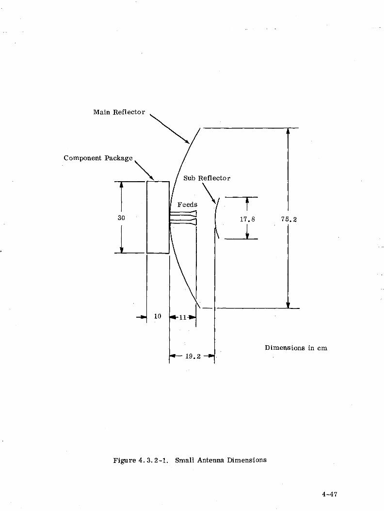
Main Reflector
Component Package
Dimensions in cm
Figure 4. 3. 2-1. Small Antenna Dimensions
4-47
The 7.5 x 4.2 CONUS beam is formed by combining all six feeds.
Beam formation is summarized in Table 4.3.2-1.
4.3.2.3 Large Reflector
The pertinent dimensions of the large reflector are shown in
Figure 4. 3.2-2. Although the feeds are not shown, the location of the
phase center is. A total of fifteen feeds are used, arranged in a
3x5 matrix with the 5 feed row aligned with the smaller reflector
dimension and the E-W direction. The feeds are waveguide fed
horns, flared in both planes to achieve tapering of the reflector
illumination. The waveguide is fed through the rear of the reflector
to the component package which houses the beam selection matrix.
The estimated weight for the matrix and feeds is 28.8 kg (64 Ibs).
An additional 13 kg (29 Ibs) is estimated for the reflectors and
support structure for a total of 41.8 kg (93 Ibs).
In the E-plane, the horn aperture dimension is 4. 5 cm and in the
H-plane the aperture is 3 cm. The horns are aligned such that
their E-planes are parallel to the plane containing the smaller
reflector dimension. This arrangement produces about a 7 dB
edge taper in both planes for the reflector. The estimated pattern
shape for this reflector illumination is a beam with half-power
width of 0. 65 x 1.3 . With respect to the 3x5 beam matrix,
beam pointing in the N-S direction is fixed at 0 and t I , while
beam pointing in the E-W direction is fixed at 0 , * 1.5 , and
t 3 . Thus the total overall pattern coverage as measured from
the outer 3 dB point of the first beam to the outer 3 dB point of
the last beam is 2.65 in the N-S direction and 7.3 in the E-W
direction. The beam cross-level in the N-S plane is estimated at
-6.4 dB, while the cross over in the E-W plane is estimated at
-4dB.
4-48
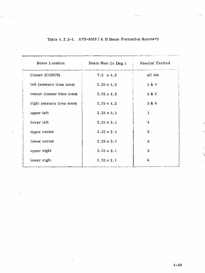
Table 4. 3. 2-1. ATS-AMS I & II Beam Formation Summary
Beam Location
Center (CONUS)
left (western time zone)
center (center time zone)
right (eastern time zone)
upper left
lower left
upper center
i lower center
upper right
lower right
Beam Size (In Deg. )
7.5 x 4.2
2 .25x 4.2
2.25 x 4.2
2.25 x 4.2
2.25 x 2.1
2.25x 2.1
2.25 x 2.1
2.25x 2.1
2.25 x 2.1
2.25 x 2. 1
Feed(s) Excited
all six ;
1 & 4j
2 & 5
3 & 6
1
'4
2
5
3
6
4-49
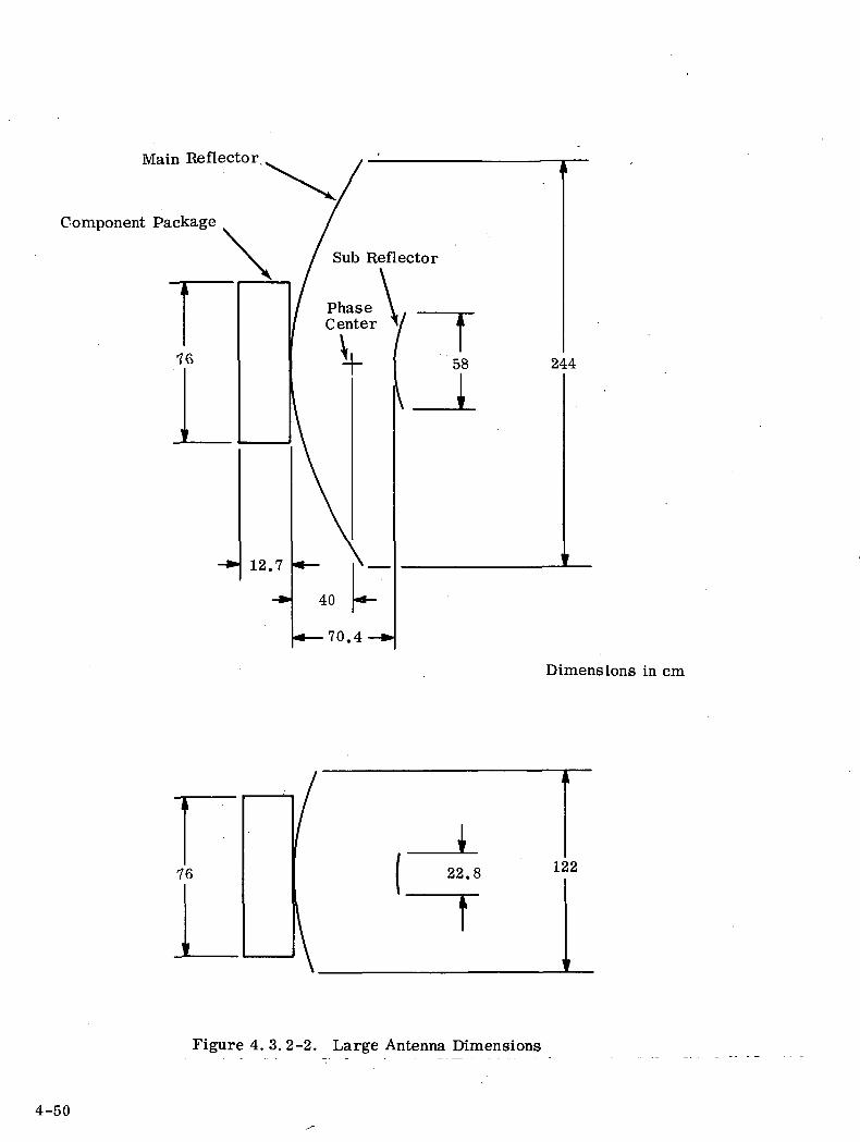
Main Reflector
Component Package
Dimensions in cm
i22.8
T122
Figure 4. 3. 2-2. Large Antenna Dimensions
4-50
The receive beam selection matrix will permit the connection of
any one of the fifteen feeds (beams) to any one channel. The trans-
mit beam selection matrix permits the connection of any of 4 feeds
to one transmit channel on an area basis. The receive matrix
with separate TDA frontends permits complete versatility with
only 0.1 dB insertion loss. While the transmit matrix does not
have complete versatility, considerable weight reduction has been
achieved, and the estimated insertion loss is only 0.3 dB.
4-51

4.4 COMMUNICATIONS TRANSPONDER SUBSYSTEM
4.4'. 1 COMMUNICATIONS FREQUENCY PLAN-ATS-AMS-HI
4.4.1.1 Choice Of Up-Link Frequencies
A Federal Communication Commission Public Notice dated July 29,
1971, gives information on the results of the recent World Admini-
strative Conference (WARC) which revised the Table of Allocations
and Articles governing conditions of use for Space Services. The
changes are scheduled to enter into force on January 1, 1973; and
require a significantly different up-link frequency band since the
U. S. proposed 12.75 - 13.25 GHz was not allocated to the FIXED-
SATELLITE service. Instead the WARC adopted the 250 MHz upband
12.5 - 12. 75 GHz region 2, shared with FIXED and MOBILE, and
the 500 MHz band 14-14. 5 GHz shared with existing services:
14. 0 - 14.3 GHz FIXED- SATELLITE (UP)
RADIONAVIGATION
14.3 - 14.4 GHz FIXED - SATELLITE (UP)
RADIONAVIGATION SATELLITE
14.4 - 14.5 GHz FIXED
FIXED - SATELLITE (UP)
MOBILE
4.4.1. 2 Down Link Frequencies-
As specified in the Statement of Work, the down-link band is 11.7 -
12. 2 GHz.
4.4.1.3 Frequency Plan (Reference Figure 4. 4.1.3-1)
Television signals carrying video/voice from ground originating
stations to the ATS-AMS in are received in the 14. 0 - 14. 5 GHz
band and transmitted to provide regional coverage at 11.7 - 12. 2
GHz. With 24.5 MHz useful bandwidth for each voice video/channel,
carriers are conservatively spaced on 30 MHz centers.
4-52
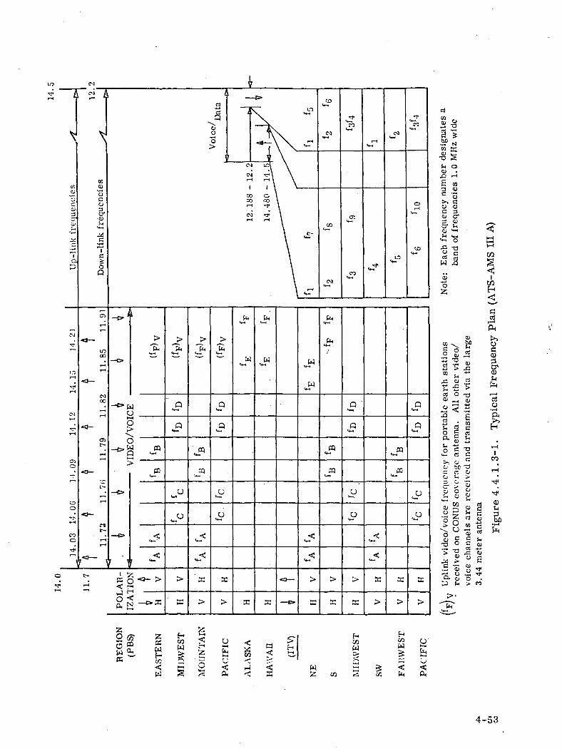
'sHr
CO
y
3o
Ia
oco3croSH
v-t
^
T—*Ic5;OQ
to £r•SS
o o<u cr3 <U
"•g -o
Si
PH
w W
05t-
' Wo(—tg
CQ PQC5o
C3
oo
C-3t-
u
RE
GIO
N
EA
ST
ER
N
WE
ST
OU
NT
AIN
O(C E
ST H
COWB:r--
<PH
4-53
For the baseline experiments, alternate beam cross polarization
and identical frequencies are used in alternate regions so that six
frequencies suffice to provide the 10 receive (uplink) and 10 transmit
(downlink)channels for ATS-AMS IE A, and three frequencies are
needed for the 5 channels for ATS-AMS IE B. Figure 4. 4.1.3-1
shows a video/voice frequency assignment plan for the PBS network.
Interactive TV experiments utilizing the full 10 channels of ATS-AMS
HI A. The frequencies for each region are designated by the same
letters indicated in the coverage patterns of Section 4.3, Antennas and
Feeds Subsystem.
Voice/data channels for interactive educational programs are in the
same frequency bands as for video/voice. Allowance has been made
for 10 uplink channels requiring 10 frequency bands for ATS-AMS
HI A, and 5 channels for ATS-AMS III B, each 1. 0 MHz wide, re-
ceived at the CONUS coverage antenna. The down-link voice/data
channels to the origination stations is sent via spot beams from the
same feeds as for the video receive channels. Again, identical
frequencies are shared in alternate zones; thus six frequency bands
suffice for ATS-AMS IE A, and three frequency bands for ATS-AMS
III B. The response to the student is on the video/voice channels with
data assigned to the baseband slot.
Sufficient frequency spectrum is available for doubling the video/
voice channels and increasing the number of audio/data channels by
at least five times to user and programmer capacity requirements,
and additional channels could be provided by ATS-AMS HI at the ex-
pense of the undefined experiments weight reserve.
4.4.2 COMMUNICATIONS TRANSPONDER - ATS-AMS-IH
4.4.2.1 General
The basic configuration for the ATS-AMS HI communications trans-
ponder and matrix assembly is shown in Figure 4.4.2-1. The video/
4-54
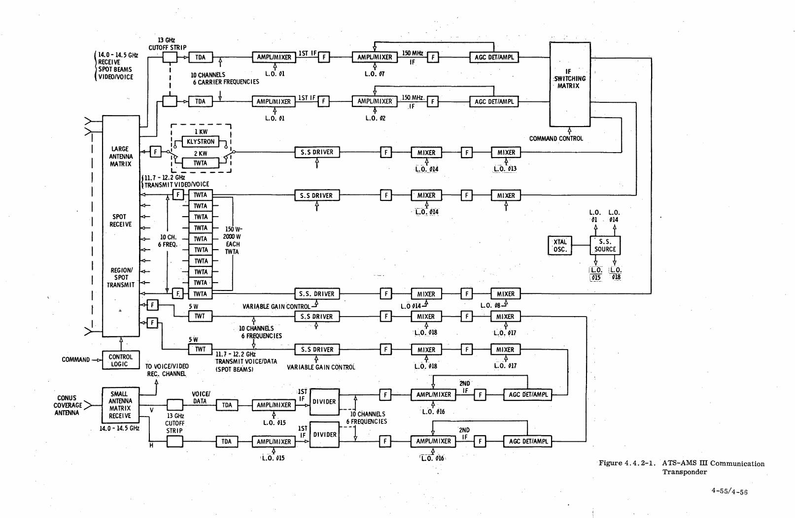
14.0-14.5 GHzRECEIVESPOT BEAMSVIDEO/VOICE
13 GHzCUTOFF STRIP
LARGEANTENNAMATRIX
SPOTRECEIVE
REGION/SPOT
TRANSMIT
T AMPL/MIXER
10 CHANNELS LO. 016 CARRIER FREQUENCIES
rTT-H TDA \ i -{ AM PL/MIXER
?LO. 01
1KW
KLYSTRON
TWTAL '
111.7 -12.2 GHz{TRANSMIT VI DEO/VOICE
ri|
rf-{ S.S DRIVER )
COMMAND •
CONUSCOVERAGE >—ANTENNA
\ AGC DET/AMPL
VARIABLE GAIN CONTROL
10 CHANNELS6 FREQUENCIES
V.MIXER | [T]-~~^
TO VOICE/VIDEOREC. CHANNa
A
11.7-12.2 GHZTRANSMIT VOICE/DATA(SPOT BEAMS) VARIABLE GAIN CONTROL
14.0-14.5 GHz
AMPL/MIXER
1STIF DIVIDER
2ND
LO. 0151ST
, IFAMPL/MIXER |—>
ILO. 015
DIVIDER
10 CHANNELS6 FREQUENCIES
AMPL/MIXER"| IF |~F~| - 1~~r.
L.O. «6
{D—1
IFSWITCHING
MATRIX
COMMAND CONTROL
AGC DET/AMPL
LO. LO.01 014
i t
T7T|LO. !L.O.1015 018
Figure 4.4.2-1. ATS-AMS III CommunicationTransponder
4-55/4-56
voice repeater is capable of:
o Receiving video/voice channels 30 MHz wide (24. 5 MHz video/
voice FM bandwidth) on spot beams on the large antenna and on
the small CONUS coverage antenna.
© Transmitting video/voice channels from the large antenna via
contoured pattern beams after translation to the 11.7 - 12 GHz
frequency band.
e Providing IF and RF switching of individual channel frequencies
and feeds upon ground command as desired to change experiments
and provide a remote feed capability.
The voice/data repeater is capable of receiving channels 1. 0 MHz
wide at 14. 0 - 14.5 GHz on the CONUS antenna, translating to the
11. 7 - 12. 2 GHz frequency band and transmitting on spot beams from
the large antenna.
4.4.2. 2 Video/Voice Transponder
The input signal is amplified in a tunnel diode amplifier (TDA) with
a gain of 15 - 20 dB and a noise figure of 6 dB nominal.
The output of the TDA is down-converted in two stages providing
optimum rejection of image frequencies. AGC controls the second
amplifier mixer output. Local oscillator (LO) signals for each
mixer stage are derived from a solid state microwave source using
a Gunn type oscillator phase locked to a crystal reference oscillator.
Intermediate frequencies at the second IF are the same (150 MHz)
for all transponders to permit flexibility of video channel switching.
IF switching is provided on individual channels (and frequencies) to
direct programs to different locations as required by each network-
ing experiment.
4-57
IF signals are amplified and up-converted in two steps to 11. 7 -
12,2 GHz with LO signals derived from the same reference oscilla-
tor as for the first LO. After filtering, each output is fed into
a high powered TWTA for transmission to the desired areas
on selected beams via the contoured pattern antenna. Nominally,
200 watts output power will supply the required power levels at
most earth station locations for the desired quality of video.
The 1000 watt Klystron or the 2000 watt TWTA is placed in opera-
tion to achieve acceptable quality video under rainfall attenuation
conditions or with 2 to 4 carriers in a backed-off mode. This latter
capability must first be developed under laboratory test conditions.
Output power control (e. g. back-off of TWT input power) is varied via
the power amplifier driver upon ground command. Solid state drivers
are IMPATT diode negative reactance amplifiers (watts of output)
and fundamental Gunn diode amplifiers (hundreds of milliwatts).
IMPATT diode amplifiers have gains of 30 dB, Gunn diode amplifiers
have 10 dB gain. Efficiencies are 6 - 10%.
Control logic is used for all switching functions and for controlling
gain (e.g. for increasing or decreasing power of TWT's). Upon
switching to the high power TWT or Klystron the high voltage is first
switched off and then reapplied when the appropriate device is con-
nected.
4.4.2.3 Voice/Data Transponder
Voice/data signals are received from multiple, widely dispersed
locations on the small CONUS coverage antenna. After pre-amplif ica-
tion (TDA), the carrier frequencies are down-converted into stages.
Following an initial down-conversion to a 1 GHz center frequency,
the composite signal is divided and filtered into individual 1. 0 MHz
frequency bands and down-converted to second IF's below 500 MHz.
Up-conversion is in two stages, with six frequency bands shared
among the ten down link channels for ATS-AMS HI A.
4-58

Five watt TWT's are used as power amplifiers. Because of the
multiple access carrier voice/data operation, the TWT's are backed
off 10.8 dB to the linear operating region of the tube to maintain
carrier-to-intermodulation product levels of 24 dB. Allowing for
antenna feed losses, the power delivered at the multibeam antenna
is 25 milliwatts per 45 kHz channel. An alternate approach is to
precede a lower power TWTA (1. 5 W) with predistortion circuitry,
resulting in the same performance with 6 dB output backoff. Multi-
carrier operation in spaceborne power amplifiers is recommended
for future experimentation and development. Solid state drivers
for the 5 watt TWTA's are linear Gunn effect devices to insure that
additional intermodulation products are not introduced at the ampli-
fier input.
4.4.2.4 Transmitter/Receiver Isolation
Isolation filters and antenna polarization are combined to reduce
transmitter out-of-band noise and transmitted output power below
the noise level of the receiver. Three and four section microwave
filters with -40 and -50 dB isolation respectively are used at the
output of each TWTA to reduce transmitter - generated noise.
Cutoff waveguide strip is inserted before the TDA in the 14 GHz
receive channel to provide -100 dB out-of-band filtering. Filters
are lightweight (ounces) at these frequencies.
4.4.2.5 Transponder Characteristics
Transponder input and output levels are summarized in Table 4.4.2.5-1.Link analyses to support these levels are included in Section 5.1.
Overall weight and prime power for the transponder is estimated
in Table 4. 4. 2. 5-2.
An outline drawing of the high powered TWTA is included in Section
5. 8, Thermal Control. The Klystron or 2000 W TWTA is not
4-59

operated simultaneously with the other TWT's except for a standby
power of about 100 watts, due to limitation of power at EOL.
Table 4.4.2.5-1. Transponder Input/ Output Levels
Type Signal Signal Level Bandwidth Output Power
Video/Voice
Voice/Data
-57 to -84 dBM
-81 dBM
24. 5 MHz
1 MHz
200 W
5 W
Receiver Noise Powers -124. 0 dBW at 24. 5 MHz bandwidth
-137. 8 dBW at 1. 0 MHz bandwidth
4-60
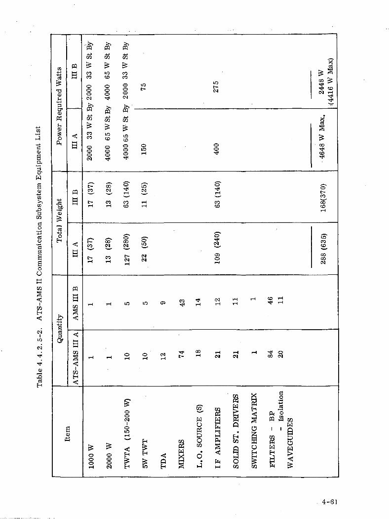
co
T30)
pqI—t
a
W
coco
PP pq& CJQ
10 co
<=> o(N
CO
8* 33£
CO
dCD
aa
•pH
CTW
oPH
coco
ooo
mco
ooo
LOcoo S § CO
w>>CO
pqa co co
>H CD
cq
coCD
coSo"CD
CQ
do
• r-t-u>cciCJ
aaoOS
—H
pq
aCOCD
GOCO
COE-"
CQ
(NI
LO
cq
cB33a-
CO 00 ••* O
o>3etiH
CQH
§
M
02 g3
aCD «
4-61

4.4.3 COMMUNICATIONS TRANSPONDER - ATS-AMS-I AND n
4.4.3.1 General
The initial Statement of Work identifies as part of mission objective
(2.1.1) the capability "To demonstrate the high power communications
technology using transmitter output of one kilowatt or more in space
in the frequency band of 11.7 - 12.2 GHz." Mission constraint 3.5
adds the requirement 3.5 for considering "Klystron and traveling
wave tubes which have efficiencies of 50% or greater" and constraint
3.14 states "The spacecraft shall be capable of repeater-type opera-
tion. "
The communication transponder concept herein described is directed
toward achieving the objectives stated in particular relating to ex-
perimentation on high power TWT's and Klystrons. The basic con-
figuration for the spaceborne communications transponder is shown
in Figure 4.4.3.1-1.
The spaceborne communications transponder for ATS-AMS-I and n
will provide a capability for receiving up to four video/voice channels
each 40 MHz wide (34 MHz usable bandwidth) in the 12.75-13.25
GHz band, on 15 separate spot beam feeds on the large antenna and
on a small CONUS coverage antenna, and for transmitting up to four
video/voice channels in the 11.7 - 12.2 GHz band on either the large
or small antenna for spot beam, region at CONUS coverage.
4.4.3.2 Transponder Description
The received signal from each beam is fed into a tunnel diode ampli-
fier (TDA) with a noise figure of about 5 dB ensuring a receiver noise
figure of approximately 6 dB. For each of the 15 spot beams into
the large antenna the output of the TDA is down-converted to inter-
mediate frequencies in the 280 - 440 MHz band by mixing with a
local oscillator signal programmed by ground command. A low pass
4-62
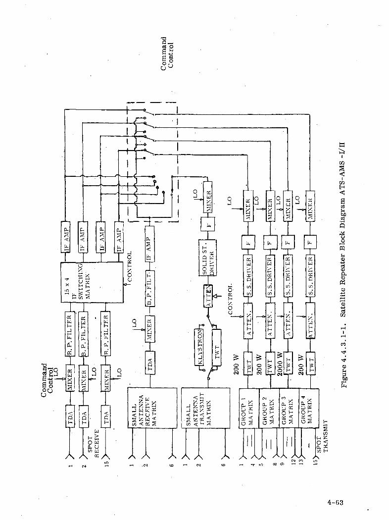
Co
^3
n,
PH
lO
ocUf-
fl
d
U
0u•*>>.t—*r
f
CF-
/
lk
(li
i'H
J
f
•1
J
J
]A
i1
a
sH
Pite-*
U-
3r'
L. i-~> a^ (-
KWH
HH
OH
35
W
Qf-
A
^
r,^
t
O
(.H ;O tD- Cw t
Q
(
q>•4
JJac
xT
-14
t
i
PSwHa
(X
UJ
1w
%
\
Ain
A
^
p»r
it-
cV
H
L,-4
3J
!
c>
1
J
o
nu
,
X1
;S}
f
V
x-V/•
3
4J<
/
\
— «
r — c
(
— c
— -a
1i
)
)
<
W
/
.c
>
k.
U.
ft
n
[] ,»—
H-
u.n
au>-
<fi-
w
RE
CE
I
\
•4
^
-T
"Y
1
5H
t;H
2f-<
fL
11
1
f? tJ 9 „ <
_J•
J J f' ~\ '
I .si* CO
A Atn ^^
~jj0
r6HITK~
S
"I
;;J /-1 «•
<°
AM
Jr
. \
t
n
•C/3
QJO
J
h
«
•o
,J :i; f
« :
t
!_.
rli)
—4
r
^u
rfl
Lu-H
H
I
\
/
f
<
ti
f.
O
L.
JO'
-*_ o:Hs*>ou
:L
H^ - ^
-J 0
1
(r
c
A x
05W
1
I
^1
XW
5Q
i/i
|
UH
<1
|
(-,
B
T-H
OnvjL
, t
MA
TH
*x /*•
O
K,H
Cr
\r
-o
5q
op*-
ac.
Ao
ffU
U
ccu>»—fT
cua
S-V(-
<i
hrfF-
\
]
4
3ii
i-i
•<
•i
_^t
IS-H
X
a
O1
J -
ooo
0
rC.'c
a
oc
•:
'*
].XUJ!rDi/i1/3
WH
<
H!?
0
H-
orv
wu
MA
TR
k /cr
o
If
cr
AVVJ
H
-fr
S
D\I
IX
GK
OU
\•T)
35U4
a^
ui
OSU,
rQint/3*
I
.
WHH•s
1H
H
I
t<Q^
sif
a)-
iiH<art
ctf
u
C3
o-M»f*-41 — 11— 1<D"rtt/2
«4 — |
1
*
*&
•*
S
H
"'
SP
OT
TR
AN
SIV
4-63
filter selects the lower sideband from the mixer output. The IF
switching matrix transfers each receive channel to the appropriate
transmit channel (s) on the four 200 watt transmitters (single carrier
on a 34 MHz useful bandwidth on each transponder) or to the 2000 W
TWTA (or 1000 W Klystron) for transmission on a single channel on
the small CONUS antenna. Up to four simultaneous channels received
on the small antenna are down converted with a single LO for up con-
version and transmission via the 1000 watt Klystron or 2000 Watt
TWT over the small antenna or for up-conversion and transmission
over one of the selected 200 Watt TWT's. A 40 MHz band pass
filter is assumed at the front end of each of the four up-converters
(mixers) to select the appropriate IF band from the 160 MHz TWT
band (100 MHz for the Klystron).
The switch matrix following the IF amplifiers performs the channel
transfer described also upon ground command. A variable gain con-
trol provides, upon ground command, the proper drive level for
either the TWT's or Klystron amplifier for various experiments and
for necessary back-off when using more than one channel.
Up to four simultaneous video channels will be transmitted by the 2 KW
TWT and no more than two RF channels by the 1000 Watt Klystron.
Redundant modules are used for each of the active solid state sub-
assemblies, except for the 15 TDA's. These are all on stand-by and
can be switched in, in event of failure or intolerable degraded per-
formance, by means of the control logic.
Control logic is used for all switching functions and for controlling
gain. Before switching the high power TWT or Klystron, the high
voltage is first switched off and then reapplied when the appropriate
device is connected, preventing the generation of high power trans-
ients with all of the attendant wide band spectral components.
4-64
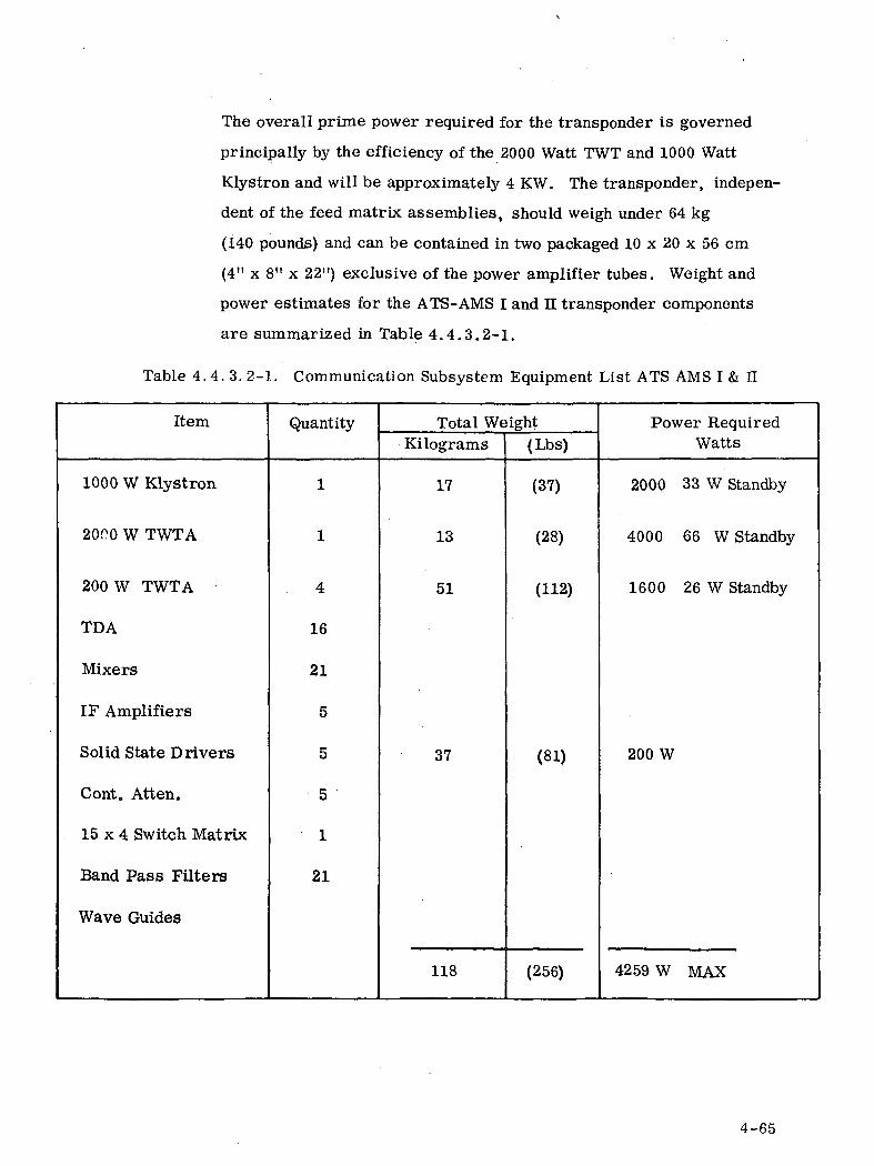
The overall prime power required for the transponder is governed
principally by the efficiency of the 2000 Watt TWT and 1000 Watt
Klystron and will be approximately 4 KW. The transponder, indepen-
dent of the feed matrix assemblies, should weigh under 64 kg
(140 pounds) and can be contained in two packaged 10 x 20 x 56 cm
(4" x 8" x 22") exclusive of the power amplifier tubes. Weight and
power estimates for the ATS-AMS I and n transponder components
are summarized in Table 4.4.3.2-1.
Table 4. 4. 3. 2-1. Communication Subsystem Equipment List ATS AMS I & II
Item
1000 W Klystron
20(^0 W TWTA
200 W TWTA
TDA
Mixers
IF Amplifiers
Solid State Drivers
Cont. Atten.
15 x 4 Switch Matrix
Band Pass Filters
Wave Guides
Quantity
1
1
4
16
21
5
5
5
1
21
Total WeightKilograms
17
13
51
37
118
(Lbs)
(37)
(28)
(112)
(81)
(256)
Power RequiredWatts
2000 33 W Standby
4000 66 W Standby
1600 26 W Standby
200 W
4259 W MAX
4-65

4.5 POWER SUPPLY SUBSYSTEM
Two power supply subsystem configurations were used in the pre-
liminary designs: Shunt Regulation and Direct Energy Transfer.
Of the two, Shunt Regulation represents the more conventional class
of space-proven power subsystems. It, too, is a form of a direct
energy transfer system in that there is no element in series between
the solar array and the low voltage loads. The selection of this
configuration for a synchronous altitude mission is supported by
many tradeoff studies*. In the AMS case it is used for housekeeping
power for the ATS-AMS I and serves as the main power supply for
the ATS-AMS-lI and HI. The second configuration, Direct Energy
Transfer, achieves power conditioning and regulation by a switching
technique that permits the transfer of power generated by the array
at high voltage directly to those spacecraft loads that require high
voltage. This configuration has been studied for its applicability as
the main power supply for the ATS-AMS-I mission and as the
configuration for the high voltage array experiments of ATS-AMS-II
and HI.
The following paragraphs summarize the characteristics and
capabilities of the power subsystems selected for each mission.
4.5.1 ATS-AMS-HI Power Subsystem Configuration
The power subsystem for ATS-III is required to provide power over
a 2-5 year period primarily from solar arrays with batteries
supplying housekeeping and communication keep alive during occult
(darkness).. With solar array degradation of 18% over the first two
years of operation available power for high voltage communications
experiments will decrease with the requirements for housekeeping,
*See, for example, Barna, G. and Newell, R., "Design of a Multi-Kilowatt Photo-voltaic Power System for Manned Space Stations", IECEC 1967.
4-66
low voltage communications and orbit control (ion engine thrust
power) expected to remain essentially constant. The PBS and ITV
communications experiments postulated have been based on available
power at the end of a two-year period. Additional increased power
experiments may be performed during the initial two years (from
start of life) as described in Section 5. 5, Power Supply Analysis.
The power supply subsystem has been sized on the maximum power
requirements anticipated.
During each day in orbit the demands placed on the power subsystem
will vary according to the following schedule during equinox:
Orbit control, once a day for 0. 5 hour will require high
voltage power for firing the ion engines, and 30. 5 VDC
communications keep-alive and housekeeping (antenna tower
drive, telemetry and command and attitude control).
Occult during equinox with periods of darkness up to 1. 2 hours
with battery power for housekeeping and communications
keep-alive.
Primary communications for the rest of the day (22. 3 hours
at equinox to 23. 5 hours at solstice). The power require-
ments are for 3. 05 VDC housekeeping and low voltage
communications; in addition to high voltage communication
and margin for undefined experiments and battery recharge
' at 67 Volts.
The power requirements for ATS-AMS-III at end of life are
summarized in Table 4. 5-1, for a typical day in orbit. The maximum
period for occult power, power for housekeeping, keep-alive for
communications and low voltage communications for ATS-AMS-ni A
and B are as outlined in Table 4. 5-2.
4-67
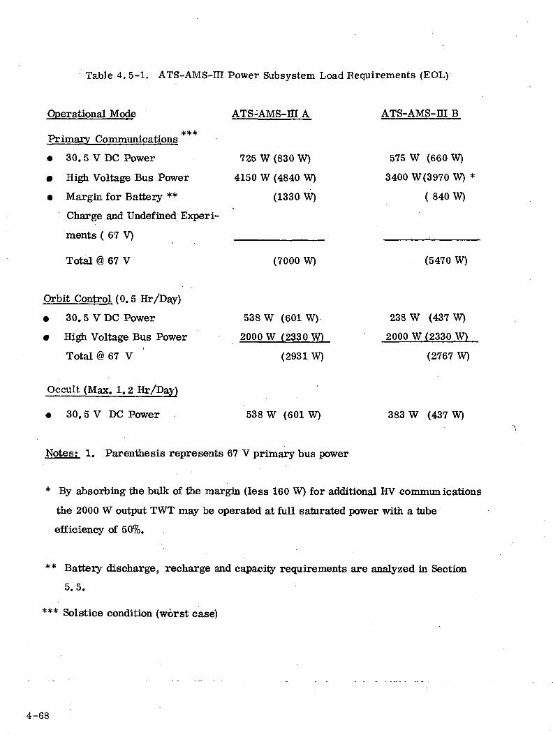
Table 4. 5-1. ATS-AMS-III Power Subsystem Load Requirements (EOL)
Operational Mode
Primary Communications ***
• 30. 5 V DC Power
• High Voltage Bus Power
• Margin for Battery **
Charge and Undefined Experi-
ments ( 67 V)
Total @ 67 V
Orbit Control (0.5 Hr/Day)
• 30.5 V DC Power
• High Voltage Bus Power
Total @ 67 V '
Occult (Max. 1.2 Hr/Day)
• 30.5 V DC Power
ATS-AMS-m A
725 W (830 W)
4150 W (4840 W)
(1330 W)
(7000 W)
538 W (601 W)
2000 W (2330 W)
(2931W)
538 W (601 W)
ATS-AMS-m B
575 W (660 W)
3400 W(3970 W) *
( 840 W)
(5470 W)
238 W (437 W)
2000 W (2330 W)
(2767 W)
383 W (437 W)
Notes; 1. Parenthesis represents 67 V primary bus power
* By absorbing the bulk of the margin (less 160 W) for additional HV communications
the 2000 W output TWT may be operated at full saturated power with a tube
efficiency of 50%.
** Battery discharge, recharge and capacity requirements are analyzed in Section
5.5.
*** Solstice condition (worst case)
4-68
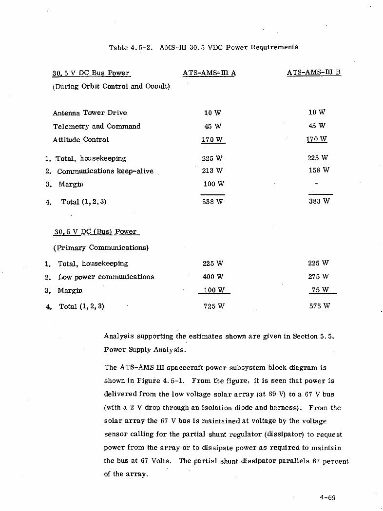
Table 4. 5-2. AMS-HI 30. 5 VDC Power Requirements
30. 5 V PC Bus Power ATS-AMS-m A ATS-AMS-m B
(During Orbit Control and Occult)
Antenna Tower Drive 10 W 10 W
Telemetry and Command 45 W 45 W
Attitude Control 170 W 170 W
1. Total, housekeeping 225 W 225 W
2. Communications keep-alive 213 W 158 W
3. Margin 100 W
4. Total (1,2,3) 538 W 383 W
30.5 V DC (Bus) Power
(Primary Communications)
1. Total, housekeeping 225 W 225 W
2. Low power communications 400 W 275 W
3. Margin 100 W 75 W
4. Total (1,2, 3) 725 W 575 W
Analysis supporting the estimates shown are given in Section 5. 5,
Power Supply Analysis.
The ATS-AMS III spacecraft power subsystem block diagram is
shown in Figure 4. 5-1. From the figure, it is seen that power is
delivered from the low voltage solar array (at 69 V) to a 67 V bus
(with a 2 V drop through an isolation diode and harness). From the
solar array the 67 V bus is maintained at voltage by the voltage
sensor calling for the partial shunt regulator (dissipator) to request
power from the array or to dissipate power as required to maintain
the bus at 67 Volts. The partial shunt dissipator parallels 67 percent
of the array.
4-69
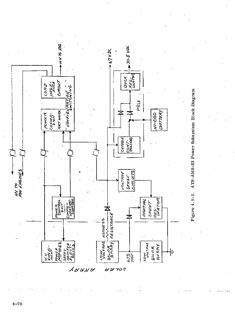
• d &•»• ^ 5$ x?Vv
IbCrt
B.«ooW
CO
OT •
O)
O
in
•*'01
4-70

The power regulation unit consists of the charge controller and
discharge (buck) regulator of the PWM (pulse width modulation)
type. The discharge regulator provides 30. 5 V power for low voltage
communication and housekeeping power from the 67 V bus during
daytime and housekeeping power from the battery during occult.
The regulator functions as a nondissipative, tapered current,
temperature compensated bucking charger. It's conversion
efficiency is 89%. Isolation diodes from both sources each take a one
volt drop. The charge controllers operating off the 67 V bus main-
tain and recharge the battery during each day to replenish the occult
discharge (maximum of 1. 2 hours/day during equinox). Each string
of batteries requires its own dissipative-type charge controller con-
taining current, voltage and temperature sensing and limiting
functions. Charge current is controlled so as not to damage the
battery with high end-of-charge voltages or overcharge rates.
The Power Converter Network conditions high voltage power for
operation of the ion engines (during orbit control) and of the power
amplifiers with power normally supplies from the 67 V bus. The
conversion efficiency is about 86%. As it is contemplated supplying
high voltage to several power amplifiers in parallel there will be a
load interface circuit providing load isolation, protection and load
switching.
Also shown in the diagram are high voltage solar array (HVSA)
modules with array-mounted electronics for conducting high voltage
experiments. The modules of the high voltage array are connected
in series-parallel combination to provide power directly to the high
voltage power loads.
The power control unit (PCU) reconfigures the power converter
network and provides voltage regulation for the HVSA. Upon ground
command, the high voltage modules can be substituted for converter
modules to supply biased high voltage directly to the load.
4-71
As shown in Figure 4. 5-1, an interface exists between the main
spacecraft body and the antenna support platform. Only DC power
is transferred across the rotating joints. Power transfer is accom-
plished by means of liquid-metal (gallium) sliprings located on the
main drive shaft. The power converter network is located on the
rotating platform thereby minimizing the number of sliprings that
must carry high voltage power. However, power at a 1. 2 kV level
will be returned from the platform to the ion engines for orbit
control. A detailed study will determine the best location for the
Power Control Unit. At present, in deference to the location of the
high voltage solar array experiment, it is located within the main
spacecraft body.
Table 4. 5-3 summarizes the characteristics of the ATS-AMS-m
power subsystem.
4. 5. 2 ATS-AMS H POWER SUBSYSTEM CONFIGURATION
The power subsystem for this direct-ascent spacecraft is required
to provide primary power at low voltage with high voltages obtained
directly from the solar array as an experiment. The Shunt Regulator
Subsystem, shown in functional block diagram form in Figure 4. 5-2,
has been selected for this application. The bulk of the array power
is generated at 30. 5 VDC. A converter network, powered from the
regulated bus, provides high voltage to the ion engines or transmitter
tubes. An on-board control unit, containing a stored-program
computer, reconfigures the network by ground commands according
to a spacecraft operational requirements. Otherwise, the shunt
regulator subsystem operates as described in the following
paragraph.
The state of the subsystem can be in only one of three operational
modes depending upon available solar array power, battery charge
4-72
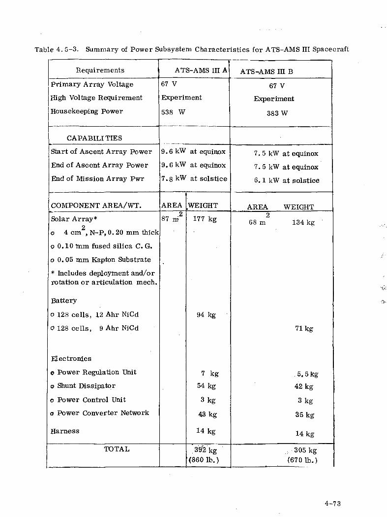
Table 4. 5-3. Summary of Power Subsystem Characteristics for ATS-AMS III Spacecraft
Requirements
Primary Array Voltage
High Voltage Requirement
Housekeeping Power
CAPABILITIES
Start of Ascent Array Power
End of Ascent Array Power
End of Mission Array Pwr
COMPONENT AREA/WT.
Solar Array*2
o 4 cm , N-P, 0. 20 mm thick
o 0.10 mm fused silica C. G.
o 0.05 mm Kapton Substrate
* Includes deployment and/orrotation or articulation mech.
Battery
o 128 cells, 12 Ahr NiCd
0128 cells, 9 Ahr NiCd
Electronics
© Power Regulation Unit
© Shunt Dissipator
o Power Control Unit
o Power Converter Network
Harness
TOTAL
ATS-AMS m.A
67 V
Experiment
538 W
9 . 6 kW at equinox
9.6 kW at equinox
7.8 kW at solstice
AREA
87 m2
.WEIGHT
177 kg
94 kg
7 kg
54kg
3kg
43kg
14kg
39'2kg(860 Ib. )
ATS-AMS m B
67 V
Experiment
383 W
7. 5 kW at equinox
7. 5 kW at equinox
6. 1 kW at solstice
AREA WEIGHT2
68 m 134 kg
71kg
5.5kg
42 kg
3kg
35kg
14kg
., 305 kg(6701b.)
4-73
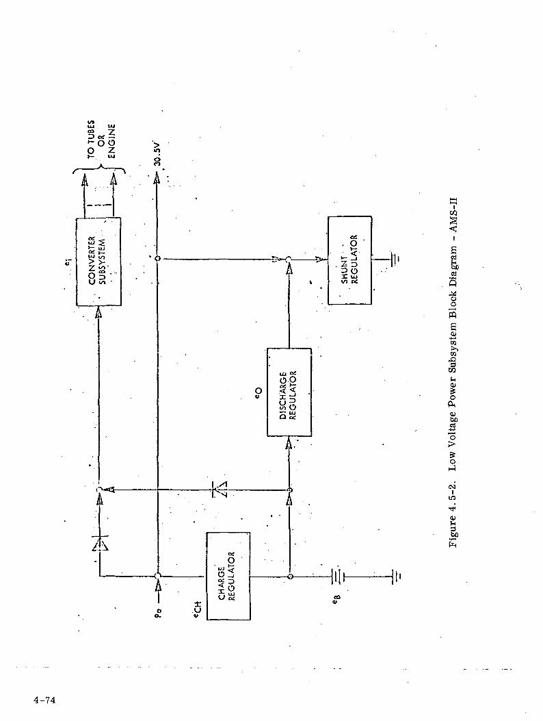
oCO
"J uo
Z ">'
oSu
A
=> 0X ujVI 0£
Hi'
UJ Oi
00
§05S
I
.0w
oiO
4-74
requirements and instantaneous spacecraft electrical loads. The
modes are: battery discharge, battery charge and shunt regulation.
In the first mode, which occurs during occult and periods of peak
demand, the battery discharges through a PWM-type voltage-boost
regulator. In the second mode the array is capable of charging the
battery and supplying spacecraft loads. In this case the dissipative-
type charge controller maintains the regulated solar array bus with
both the boost and shunt regulators turned OFF. The third mode
occurs when array power is in excess of load and battery charge
requirements. The shunt regulator dissipates this excess and acts
to maintain voltage regulation. The three regulators are turned ON
and OFF in proper sequence and proportioned as a result of the
measurement of very small changes in regulated bus voltage which
correspond to source - load power conditions.
The solar array design features will be similar to the blanket-type
array later described in detail for the ATS-AMS I mission. Its area,
however, will be 51 m^ (550 ft^). Other subsystem characteristics
are summarized in Table 4. 5-4.
The high voltage array experiment requires 0. 9 m (9. 7 ft^) allocated
to two 1000 VDC blocks of solar cells. The blocks each contain
nearly 4000 1x1 cm solar cells, blocking and coupling diodes, and
semiconductor load, stacking, shorting and regulating switches.
Configuration experiments and voltage regulation are controlled
from the on-board computer which is otherwise used to reconfigure
the modular converter network. Upon ground command, the blocks
can be substituted for converter modules to provide biased high
voltage to the transmitters. The experiment can be located either on
array or, as described earlier, on the sun-facing side of the
spacecraft.
4-75
4. 5. 3 ATS-AMS I POWER SUBSYSTEM CONFIGURATION
The ATS-AMS I mission requires that the solar cell array be capable
of providing power to a cluster of ion engines during spiral-out
ascent from low to synchronous orbit and then be capable of recon-
figuration to provide high power at high voltages to TWT and Klystron
transmitters. Sections of the array will be dedicated to categories
of voltage requirements summarized as follows:
• Attitude control, telemetry, battery charging and other house-
keeping requirements at 30. 5 V nominal,
• Ion engine requirements with accelerator and screen voltages
up to 1. 2 kV,
• RF power amplifier requirements with cathode and collector
voltages up to 16 kV,
• Special experiment voltages as required.
A functional block diagram of the ATS-AMS I power subsystem
configuration is shown in Figure 4. 5-3. The solar array is divided
into low and high voltage sections. The low voltage section delivers
power at 30. 5 V through a shunt regulator power subsystem to the
housekeeping loads. The high voltage section contains blocks or
modules, capable of delivering nominally 1000 V. The blocks are
connected in the proper series - parallel combination to provide
power directly to the high voltage high power loads. Precise vol-
tage regulation across a series chain of blocks is achieved by
shorting out the proper number of series solar cells in each block.
The reconfiguration and regulation functions are controlled by an
on-board computer on a continuous basis. Although the low and high
voltage arrays are shown independently, it is possible that, upon
detailed trade-off and optimization analysis, the sections could be
combined with a net savings of array area and weight.
4-76
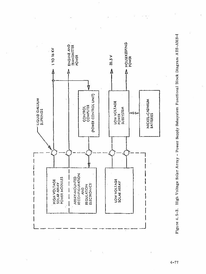
V•o
OZ<
OZ
<toH
2 oi-5 « §|*" z2.0 o go•— uj v— n. *"> ^ U
X a-
^
c\
5^.
<„.OoQ Z
D ^23_i «/i-1I\\
\<
1 /
T rr i
t^in UJUJ .
%>^s|so 3 5> c£ OH.
X < £o — ' >^ O OX to o.
\ k A
JiV*— *K~
Z3 UJ_i O
-J2 O < <:• o^ ^ i^ s^ -3 \— — ' UJ£ rT -7 O *~ -c tii.
Z5 § >£> ^^OO u $ 5 £uu a: O O r>
uj _i a. i
Os>
1 i 11>_ _,__ A A r>j • \)~ -\> -\J —
Vz
I /"\ oQ VJUJ ~~ UJ
^ < . o>-z 2 z «". «!3 3 *- U >- o;O r^ Q O -1 °Js ^ z ^ z o<:•f « o > V ^- — ' 2 -s- < O D t~i > -1
1§ i2^ 28~5? LU LLJ »J ~* vi
<l a; o: LU
1
aat-ibjjrrttu
Q^ooS
"3o•1
"o
^ §' 2 h'I a
< 0)> * 1 u oo t;i ui i?_i — . >iUJ °& COV-£ J2Oh- 3^< w
"D,a3
O3t ,HQJ&O
ft~~1
1 -1 h1 ^1 <I ^S
1 ^1 rrtJS1 0• CO
"' beI O S
-"0
1 >§1 a
1 <?
I . ILO
QJ
4-77
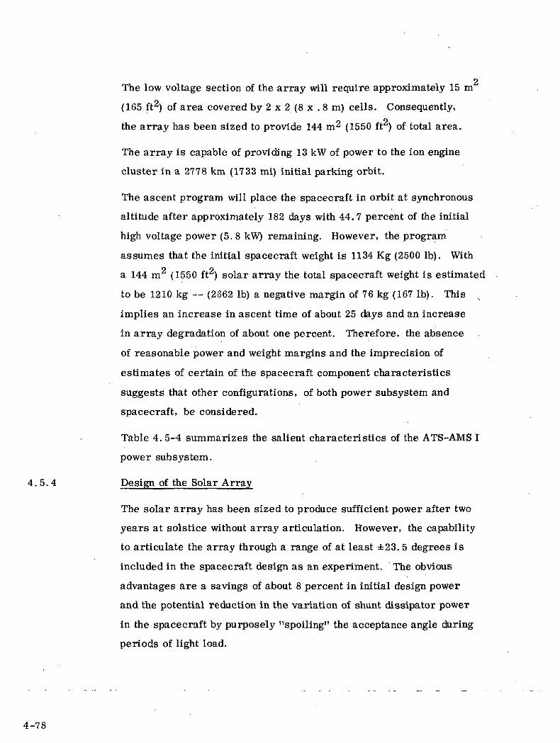
oThe low voltage section of the array will require approximately 15 m
(165 ft2) of area covered by 2 x 2 (8 x . 8 m) cells. Consequently,
the array has been sized to provide 144 m2 (1550 ft ) of total area.
The array is capable of providing 13 kW of power to the ion engine
cluster in a 2778 km (1733 mi) initial parking orbit.
The ascent program will place the spacecraft in orbit at synchronous
altitude after approximately 182 days with 44.7 percent of the initial
high voltage power (5.8 kW) remaining. However, the program
assumes that the initial spacecraft weight is 1134 Kg (2500 Ib). With
a 144 m (1550 ft2) solar array the total spacecraft weight is estimated
to be 1210 kg — (2662 Ib) a negative margin of 76 kg (167 Ib). This v
implies an increase in ascent time of about 25 days and an increase
in array degradation of about one percent. Therefore, the absence
of reasonable power and weight margins and the imprecision of
estimates of certain of the spacecraft component characteristics
suggests that other configurations, of both power subsystem and
spacecraft, be considered.
Table 4. 5-4 summarizes the salient characteristics of the ATS-AMS I
power subsystem.
4.5.4 Design of the Solar Array
The solar array has been sized to produce sufficient power after two
years at solstice without array articulation. However, the capability
to articulate the array through a range of at least ±23. 5 degrees is
included in the spacecraft design as an experiment. The obvious
advantages are a savings of about 8 percent in initial design power
and the potential reduction in the variation of shunt dissipator power
in the spacecraft by purposely "spoiling" the acceptance angle during
periods of light load.
4-78
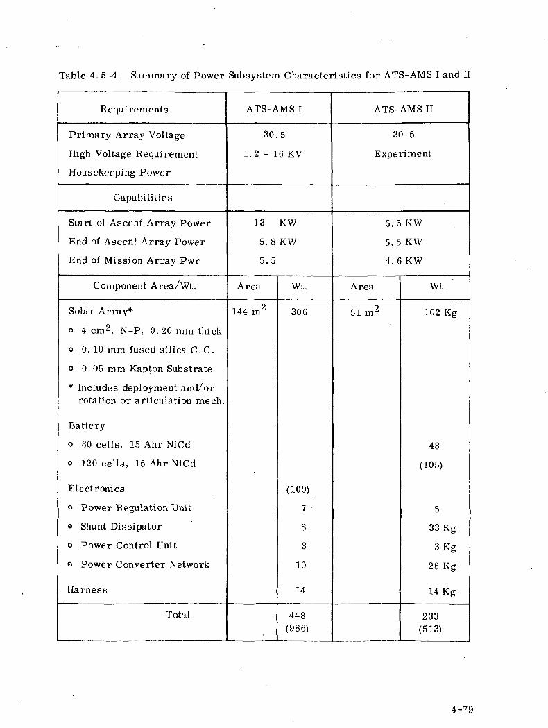
Table 4. 5-4. Summary of Power Subsystem Characteristics for ATS-AMS I and II
Requirements
Primary Array Voltage
High Voltage Requirement
Housekeeping Power
Capabilities
Start of Ascent Array Power
End of Ascent Array Power
End of Mission Array Pwr
Component Area/Wt.
Solar Array*
o 4 cm2, N-P, 0.20 mm thick
o 0. 10 mm fused silica C.G.
o 0. 05 mm Kapton Substrate
* Includes deployment and/orrotation or articulation meeh.
Battery
o 60 cells, 15 Ahr NiCd
o 120 cells, 15 Ahr NiCd
Electronics
o Power Regulation Unit
© Shunt Dissipator
o Power Control Unit
o Power Converter Network
Harness
Total
ATS-AMS I
30.5
1 . 2 - 1 6 KV
13 KW
5.8 KW
5.5
Area
144 m2
Wt.
306
(100)
7
8
3
10
14
448(986)
ATS-AMS II
30.5
Experiment
5 . 5 K W
5. 5 KW
4. 6KW
Area
51 m2
Wt.
102 Kg
48
(105)
5
33 Kg
3 Kg
28 Kg
14 Kg
233(513)
4-79
The solar array system for ATS-AMS-HI is similar to that for
ATS-AMS I and II.
One of the panels for a solar array system, similar to that shown for
ATS-AMS-HI, is shown for ATS-AMS I and n in Figure 4. 5-4.
It consists of identical arrays deployed on each side of the spacecraft.
The arrays are non-rotating and non-retracting. Each array has a
drum for storing the array during launch, a folding arm linkage,
launch restraint structure and an array mechanism. No slip rings are
required for powering the attitude control ion engines since these
engines and their fuel are mounted on the end of the deployed boom.
The engines are mounted to fire parallel to the axis of the boom and to
provide attitude control of the spacecraft by electronically deflecting
the thrust vector.
In the ATS-AMS El A case, the array aspect ratio is 9.55 to 1 (corres-
ponding to an 87 square meter area). The array width of 244 cm (96 inches)
is limited above by the antenna view angle of 1.5 and below by the ion
engine contamination boundary. This boundary is the smallest view
angle from the array to the engine nozzle with a projected nozzle shielding
to exit material with a greater than 15 included plume angle. It is
assumed that above this boundary line the array performance will not be
affected by contaminants coming from the engines.
The array is deployed in a two step operation with the linkage extending
first and the array extension following. Linkage deployment consists
of releasing 5 hinged arms which are extendable from the spacecraft.
The hinges are spring loaded to deploy the arm when a restraining
cable is cut. Initial deployment is insured with a kick s pring. The kick
spring is necessary to overcome the small mechanical advantage of the
torsion springs at full stowage.
4-80
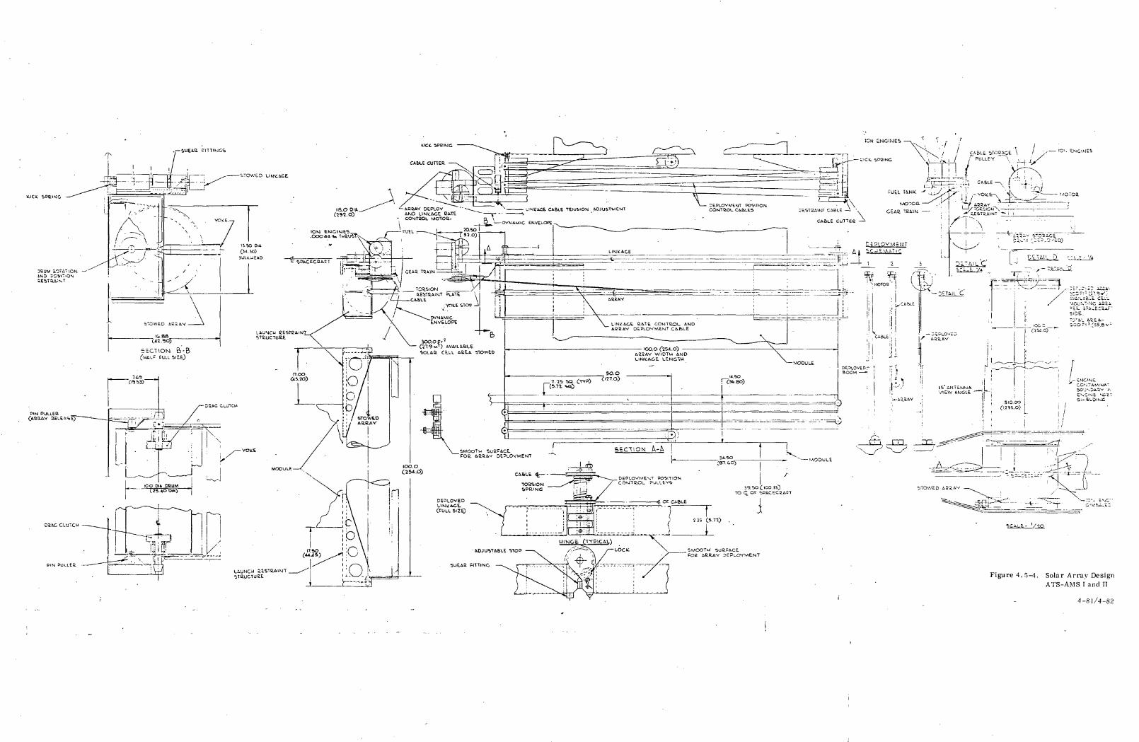
K.ICH SPUING
PIN PUL.LEC.
• ^ \ ' 'J* ^
-
/X
',<\
STOWED ACi&Y J
IC..S6 _C4?.^0) ^
JULU
.1 ' ' '
,*v _^x—Figure 4.5-4. Solar Array Design
ATS-AMS I and II
4-81/4-82
The arms deploy in a programmed manner by using a parallel arm
linkage system. The arms have pulleys fastened to them at the hinges.
Cables wrapped around pulleys attached to alternate arms require that
alternate arms rotate relative to one another. Using equal pulley dia-
meters, alternate arms deploy parallel in a controlled manner. Different
relative arm rotations are achieved by using different pulley diameters.
The rate that the linkage deploys is controlled by a motor, worm, gear
train, drum, and cable system mounted on the end of the last arm. This
same system is later used to deploy the array. A cable stored on the
drum is attached to the fixed, stowed array. The rate that this cable
unwinds from its storage drum on the last arm limits the arm deployment
rate. Storage drum rotation is controlled by a DC motor, worm, and
gear train.
Upon deployment the arms lock together forming a boom. The locks
are positive, antibackla sh, spring loaded locks. An adjustable stop
insures boom alignment after deployment.
Launch loads from the folded arms are transmitted to the spacecraft by
shear fittings on the hinges. These fittings are self-releasing when a
launch restraint cable located beside them is cut by either of two pyro-
technics.
After deployment a structural boom is formed. One surface of the boom
is designed to be smooth for the subsequent array deployment.
Array deployment is initiated by severing a cable which restrains the
array in the launch restraint structure. The motor on the boom end
winds up the cable attac hed to the array yoke and pulls the yoke and
drum toward the boom end. Since one edge of the array is attached to
4-83
the spacecraft, the bearing mounted array drum rotates relative to thef
tra nslating yoke and deploys the array from the drum. A drag clutch on
the yoke-drum shaft maintains array tension during deployment. The
array unwinds from the drum such that there is no relative motion
between the array and the boom. When the yoke and array drum reach
the end of the boom they snap under an array torsion restraint plate.
This plate is oversized to ensure yoke engagement and provide adequate
array torsion control for the deployed system. No array torsion controls
are used during deployment of the array. Array tension is determined
by the drum-yoke drag clutch.
The array launch restraint structure transfers all array launch
loads to the equipment module structure. The array is stored on
a 25.4 cm (10 in) diameter drum. This diameter was determined from
experimentation to be adequate for storage of the array. A small
shift of the spacecraft occurs during array deployment. This shift
is caused by the array changing its effective mass center from on
the storage drum to beside the boom.
The high voltage solar array experiment will be located on the sun-
facing side of the Equipment Module. It will consist of two blocks of
1x1 cm (. 4 x . 4 in) solar cells, each block capable of providing 10002 2 2
VDC. Of the 3.4 m (36. 6 ft ) area available for solar cells, only 0. 9 m2
(9. 7 ft ) will be utilized to permit Optical Solar Reflector (OSR) tempera-
ture control. Accordingly, with 73 per cent OSR coverage, the solar
cell temperature will be rough
ture measurement conditions.
cell temperature will be roughly 308 K, 280 K from standard tempera-
4-84
The solar array blanket structure proposed for all of the ATS-AMS
spacecraft consists of solar cells of 2 x 2 cm (. 8 x . 8 in) size or
less, 0. 20 mm (0. 008 inch) thick with 0. 10 mm (0. 004 inch) fused
silica coverslides bonded to a 0.05 mm (0.002 inch) thick Kapton
substrate. The average bare solar cell efficiency under 1 AU,
301°K of C start-or-mission condition is 11.4 percent. The estimated
area density of the array blanket including interconnections and
power switching electronics, is 4. 83 kg/m2 (0. 204 Ib/ft ).
4.5.5 Power Converter Network (PCN)
For ATS-AMS ni power conversion from the 67 V primary bus is re-
quired to provide high voltage for the ion engine(s) and for multiple
power amplifiers (power amplifiers are on standby during orbit con-
trol when powering the ion engines). High voltage requirements
for the TWT' s and Klystron differ from that of the ion engine re-
quiring reconfiguration of the PCN. -
Figure 4. 5-5 shows a simplified schematic diagram of a single
TWT assembly with the high voltage supplies connected. Eight
collector supply voltages are provided by two multiple secondary
converters, each sensing a single output.
The 10 kV cathode supply is provided by a single converter using
two, paralleled primary transformers with secondaries in series.
Preliminary trade-offs have indicated that due to high voltage in-
sulation and turns ratio requirements, the two-transformers,
multiple secondary scheme appears to be optimum from size and
4-85
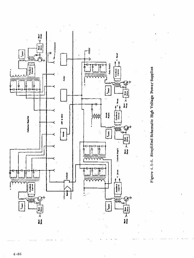
rnprv>or
j!lo8
UxJ
ij3
r" rIH]rIHUUUL Luuu JUUL
nonnnnrv
f
• 1 1
Li*£|s• u
Ti!
Tt Sli
03
a&
I<ObO
I
s0)Xu
CQt30)
afi
•M<CQ
1CI
LD
•*'
O)
3be
4-86
efficiency standpoints. Voltage sensing of the total secondary
voltage is planned in order to achieve the specified regulation. Voltage
adjustment can be easily achieved through the feedback control cir-
cuits.
The jump supply will employ multiple secondaries as shown in order
to reduce the turns ratio between primary and secondary. Only one
transformer is indicated. The anode supply is the smallest of the
high voltage supplies in both voltage and power. Regulation require-
ments, however, dictate use of the full compliment of control circuitry.
For both jump and anode supplies, full output sensing will be required.
In the configuration shown conversion is based on the half-wave single
step technique for converting from source (input) to the load (output).
The power converter network (PCN) for ATS-AMS-III will supply high
voltage loads for up to ten 200 W TWTTs (in A), a 2000 W TWT, a
1000 W Klystron, 5 W TWT's (Audio) and the ion engine.
The different power requirements for ion engines and the need for re-
configuration in shifting load between TWT's (e. g., replacing 200 W
TWT's with a 2000 W TWT or Klystron) favors consideration of separate
power supplies for each unit. Further study is required to evaluate
the separate VS combined supply approach with potential weight saving
at the expense of complexity favoring the single supply with a combined
PCN. The latter approach has been postulated with weight estimates
made for a PCN for ATS-AMS-IE A and B as described in Section 5.5.
Several techniques have been considered for the DC-DC (67 V to HV)
conversion to provide both level-setting and regulation. Both single
step and two-step conversion techniques have been studied. The two-
step approach is more complex but generally has superior dynamic regu-
lation and output level characteristics. Based on efficiency, relatively
low parts counts and output bus characteristics a single step half-wave
conversion technique representing the best compromise and 'is
suggested for ATS-AMS-HI.
4-87
4.5.6 Load Interface Circuit (LIC) and Reconfiguration Circuit
Interconnection of the Power Control Network and the various High
Voltage Loads will be through the Load Interface Circuit. Each in-
dividual load will be capable of being energized or de-energized by
ground command. Switching will be via high voltage reed relay
assemblies configured specifically for this purpose. In addition,each
high voltage lead will be fused for protective reasons and will have a
fuse-defeat circuit,which upon ground command, may permit reactuation
or "Try-again" techniques in the event of tube failure due to a
partial short circuit.
In summary, the LIC acts as a switching and distribution system for
the High Voltage Loads and also provide protection to the PCN.
Figure 4.5-6 represents a typical Load Interface Circuit showing the
energize-de-energize and the fuse defeat relays. There will be a
similar LIC for each high voltage load.
The Reconfiguration Circuit upon receiving appropriate ground
commands modifies the PCN circuits to provide the output voltage
levels required for the particular operational mode desired. This is
done by changing the individual building-block voltages and by combining
them via suitable relay arrangements. The individual output voltages
may be varied by changing reference voltages.
4-88
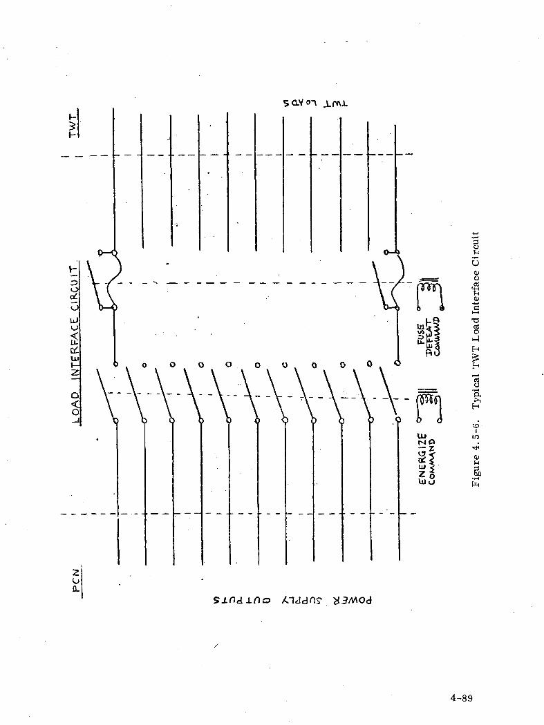
I-3
ouJ
litt-J2
Q<O
o-feOcuo
QJ-*->Ch-1
T3gh-iH
H
to-i
•<*
0)
I
sj.ndj.no
4-89

4.6 ATTITUDE CONTROL SUBSYTEM
4.6.1 SUBSYSTEM OPERATION AND REQUIREMENTS
The attitude control subsystem (ACS) is required to establish and maintain the
attitude of the spacecraft and its payload such that in the primary
control mode the boresight axis of the antenna beams point to the desired
location on Earth with a tolerance of + 0.2° for longitude and latitude,
which when converted to the spacecraft angular rotations about the
orbit normal and the orbit tangent axes of the body-fixed reference frame
amount to + 0.03 tolerance at the geosynchronous equatorial orbit
altitude. A similar tolerance of +_ 0.03 is also required for the space-
craft attitude about the third axis of the mentioned reference frame (local
vertical) since angular motions about this axis affect the longitude or the
latitude of antenna beams not pointing along the local vertical, but offset
respectively along the local meridian or the equator. The ACS
is also required to orient the flats of the solar arrays so that the per-
pendicular to their surface tracks the projection of the spacecraft - sun
line in the orbit plane with a tolerance of _+ 0.5 .
As it is described in Section 4.1, the spacecraft configurations ATS-AMS III
and ATS-AMS II are Sun oriented with an Earth oriented rotating antenna
tower while ATS-AMS I is Earth oriented with (Sun oriented) rotating
solar arrays. For attitude control purposes, it is convenient to define
reference frames. The first one, also referred to as the orbital reference
frame is defined as follows:
OXYZ Orthogonal (Cartesian) axes with the origin at the space-
craft center of mass
OX Roll axis, tangent to the orbit and oriented in the direction
of motion
OY Pitch axis, perpendicular to the orbit plane and oriented
in the direction N-S (for an equatorial orbit)
4-90
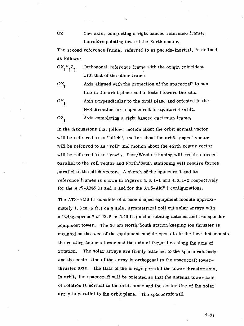
OZ Yaw axis, completing a right handed reference frame,
therefore pointing toward the Earth center.
The second reference frame, referred to as pseudo-inertial, is defined
as follows:
OXY Z Orthogonal reference frame with the origin coincident
with that of the other frame
OX Axis aligned with the projection of the spacecraft to sun
line in the orbit plane and oriented toward the sun.
OY Axis perpendicular to the orbit plane and oriented in the
N-S direction for a spacecraft in equatorial orbit.
OZ Axis completing a right handed cartesian frame.
In the discussions that follow, motion about the orbit normal vector
will be referred to as "pitch", motion about the orbit tangent vector
will be referred to as "roll" and motion about the earth center vector
will be referred to as "yaw"0 East/West stationing will require forces
parallel to the roll vector and North/South stationing will require forces
parallel to the pitch vector,, A sketch of the spacecraft and its
reference frames is shown in Figures 4. 6.1-1 and 4.6.1-2 respectively
for the ATS-AMS III and II and for the ATS-AMS I configurations.
The ATS-AMS III consists of a cube shaped equipment module approxi-
mately 1. 8 m (6 ft.) on a side^ symmetrical roll out solar arrays with
a "wing-spread" of 42. 5 m (140 ft.) and a rotating antenna and transponder
equipment tower. The 30 cm North/South station keeping ion thruster is
mounted on the face of the equipment module opposite to the face that mounts
the rotating antenna tower and the axis of thrust lies along the axis of
rotation. The solar arrays are firmly attached to the spacecraft body
and the center line of the array is orthogonal to the spacecraft tower-
thruster axis. The flats of the arrays parallel the tower thruster axis.
In orbit, the spacecraft will be oriented so that the antenna tower axis
of rotation is normal to the orbit plane and the center line of the solar
array is parallel to the orbit plane. The spacecraft will
4-91
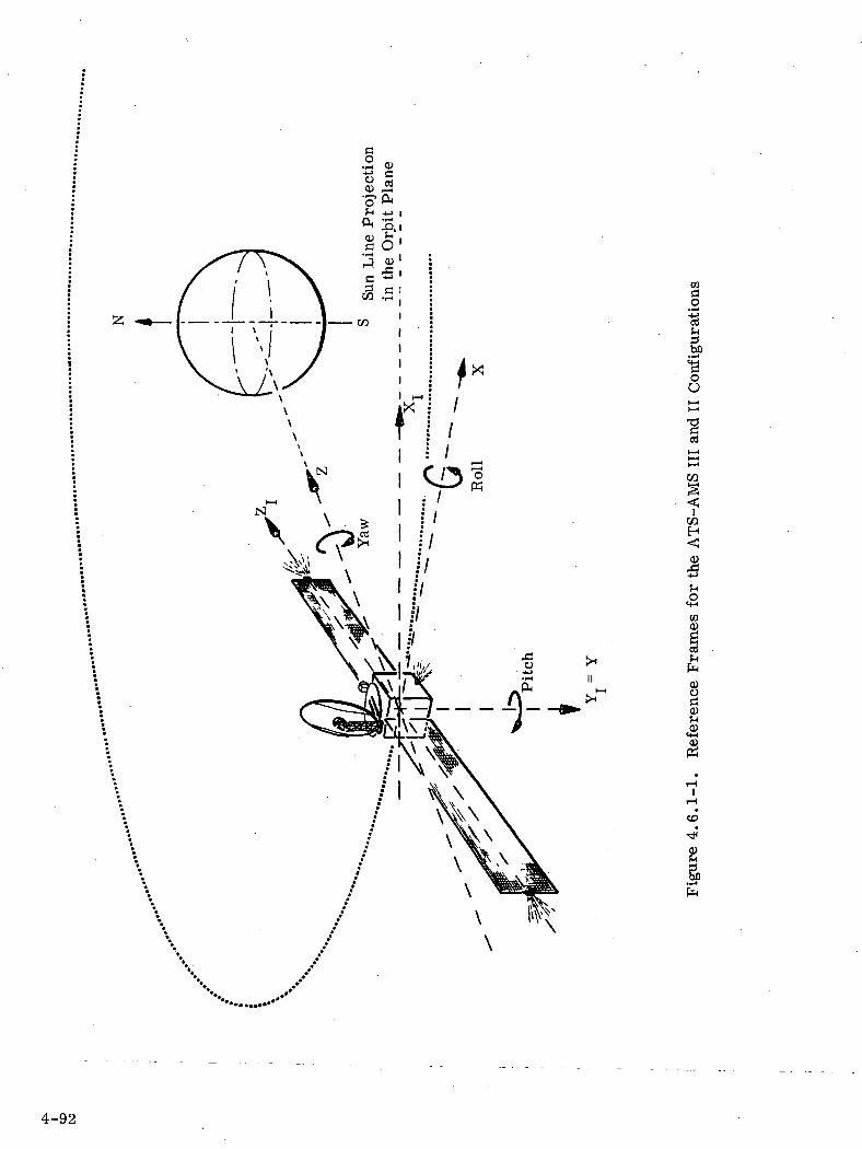
03
oo
ins<OTH
CO0)
I0)J-l
IT-t
*CO
fa
4-92
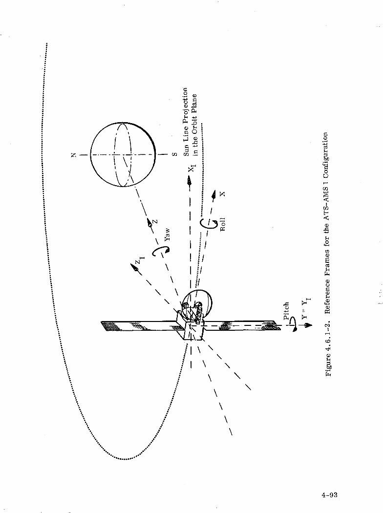
CO
oo
CO
VIo>art
O>oO>
H~ &H CMQ)
I PJH
•&• C*
\—I
CO
o>
\
4-93
be controlled in pitch to maintain the flats of the array normal to theprojection of the sun line in the orbit plane except when the array is purposely
misaligned for power regulating purposes. The spacecraft will be
controlled in roll and yaw to maintain the tower-thruster axis normal
to the orbit plane. An antenna drive servo loop utilizing either an
earth sensor or an interferometer will be used to control the east-west
orientation of the antenna beam. It is currently planned to fix the north-
south axis of the beam by locating the antenna and feed structure on the
spacecraft such that with the pitch axis normal to the orbit, the antenna
beam center will be at the desired latitude. A capability for north-
south articulation of the antenna and feed could be incorporated into the
spacecraft design without significant weight, cost or complexity penalities.
It should be noted that with this spacecraft configuration and with the
reference frame selected, the solar array centerliae alternately parallels
the roll and yaw axes.
The ATS-AMS II is basically similar to the one previously described.
The ATS-AMS I configuration is also similar except for the following
elements:
1. The equipment module is Earth oriented, thus the antenna
and RF equipment are rigidly attached to the module.
2. A solar array drive is used to decouple the array motion from
the spacecraft orbital motion, thus maintaining the array
oriented to the Sun.
3. The spin axis of the array, also their centerline, is the
pitch axis. Thus the antenna tower axis is oriented along
the roll axis.
4. The spacecraft will be controlled in roll and pitch in order
to control the N-S and E-W orientation of the antenna beam
and in yaw in order to control both orientations for antenna
beam pointing offset from the local vertical,,
4-94

4.6.2 ACS CONFIGURATION FOR ATS-AMS IE & II
The attitude control concept selected for the ATS-AMS III and II con-
figurations is three-axis stabilization using momentum storage devices
(momentum wheels) complemented by 5 cm ion thrusters. The storage
devices will control or store momentum due to cyclical torques on the
spacecraft and the ion thrusters will overcome long term constant dis-
turbance torques by periodically desaturating the storage devices by
expelling mass from the spacecraft. Three momentum wheels (one
for each pseudo-inertia! axis) will be mounted on the equipment module
to provide control torques about the XL Yj, and Zj axes. A vectorable
set of thrusters mounted at the tips of the solar array erection masts
are used for obtaining complementary control torques about the Xi and
YX axes.
An additional set of 5 cm ion thrusters will be located on the equipment
module as indicated in Figure 4.6.1-1 to provide torquing capability
about the Zj axis.
Disturbance torques acting on the spacecraft arise from solar radiation
pressure, gravity gradient, spacecraft magnetic moment and moving
masses within the spacecraft. These torques have both secular and cyclic
components. Solar disturbance torques will be predominantly secular
and gravity gradient torques will be predominantly cyclic. The mass
properties, the secular and the cyclic disturbance torque magnitude for
the ATS-AMS III spacecraft are approximately:
PseudoInertialAxes
X
YI
Z/ I
Moment of Inertia Secular Disturbance Cyclic DisturbanceTorque Torque
k 2 fshie-ftt2 Newton-meters (ft-lb) Newton-meter
Oc 1 f\f\ ft Q Gf\(\ \2o,10u ( lo ,bUU)
23,900 (17,700) 4.06xlO~
2,300 ( 1,700) 12.3xlO~5
—8t -I Q .rl A•riOXlU
/•? m --i n ^ -i-i Q d.v^ n^Oo v J.^k_L v / ' J. vt ^AX V
(9015xlO~5) +5007xlO~5
(ft-lb)
(+13.3xlO~8)
(+14.4xlO~5)
(+3076xlO~5)
Slug-ft2 = 1.35 kg-m2; ft-lb = 1.35 Newton-meter
4-95
The control torques obtainable from the 5 cm ion thrusters mounted on
the equipment module (Z\ axis torques) are approximately one order of
magnitude larger than the Zj axis solar disturbance torques and are
therefore sufficient for attitude control. The momentum storage
capability of the momentum wheels was selected to provide in excess
of an integrated half cycle of cyclic disturbance.
A backup hydrazine reaction control subsystem, similar to that used
for ATS-F/G was also selected. This subsystem would feature 0.222 N
(0.05 Ibf) thrusters mounted on the spacecraft equipment module.
The location, orientation and number of these thrusters is given by
Figure 4.6.2-1. The primary use of this subsystem will be to provide
for East/West station keeping. Tankage and plumbing is such that a
backup dual redundancy for both directions of station keeping, unload-
ing of momentum wheels, and all three axes of attitude control can be
achieved, for a 1725 kg (3800 Ib) spacecraft, at a weight penalty of
approximately 40.7 kg (89.5 Ib) per year.
The three axis stabilization concept described will provide spacecraft
stabilization relative to the pseudo-inertia! reference frame. The
antenna drive servo loop, utilizing either an earth sensor or an inter-
ferometer will be used to provide an antenna tower spin rate of 1 r/day
for antenna beam pointing on earth and pitch axis attitude control.
The functional block diagram describing the overall ACS configuration
is given in Figure 4.6.2-2.
4-96
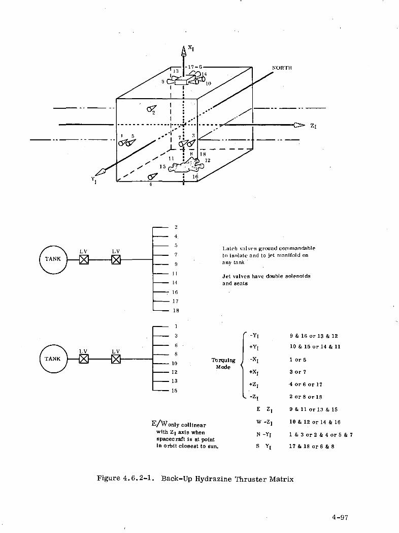
NORTH
LV
2
4.
r>7
9
11
14
16
17
18
1
3
6
8
10
12
13
15
Latch valves ground commandableto isolate and to jet man i fo ld onany tank
Jet valves have double solenoidsand seats
TorqulngMode
E/Wonly colllnearwith Zi axis whenspacecraft is at pointIn orbit closest to sun.
-YI
I*, -z I
W 7I
N-YIS Y
9 & 16 or 13 & 12
10 & 15 or 14 & 11
1 or 5
3 or 7
4 or 6 or 17
2 or 8 or 18
9 & 11 or 13 & 15
10 & 12 or 14 & 16
I & 3 o r 2 & 4 o r 5 & 7
17 & 18 or 6 & 8
Figure 4.6.2-1. Back-Up Hydrazine Thruster Matrix
4-97
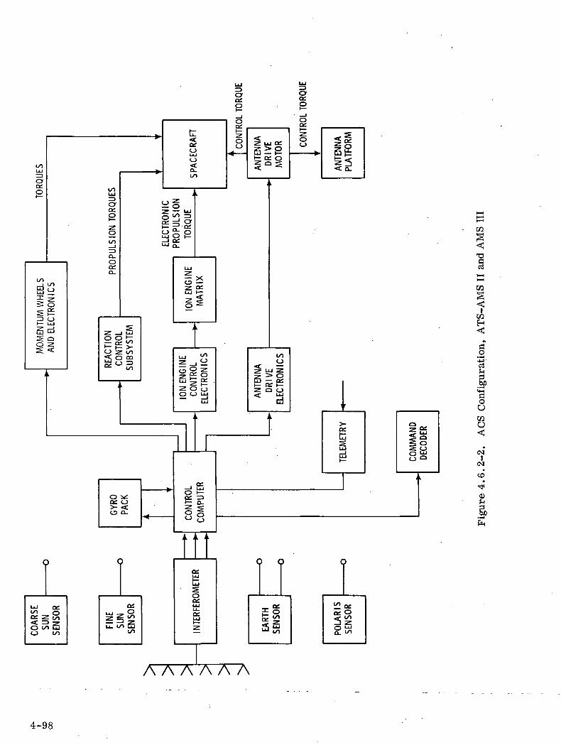
crO*o
cr
<T3
£3O•-^-M-edh=3
ooCOO<C
(N
0)h
A A A A A A
4-98

The sensor, actuators and associated electronics composing the ACS for
the configurations ATS-AMS II and III are listed in Table 4.6.2-1, which
include component weight and power. The ATS-AMS in and II, being
injected directly into synchronous equatorial orbit, would not require the
IRU (Inertial Reference Unit) which is required for the I configuration. A
rate gyro package is, however, required for acquisition purposes. A
number of control modes are possible and the use of the control computer
is used to resolve the spacecraft referenced sensor outputs into the orbit
centered attitude reference frame and to reconfigure the control laws to
permit alternate modes of control.
Table 4.6.2-1. ACS Components for ATS-AMS II & III
WEIGHTEQUIPMENT NUMBER OF UNIT kg (lb)
Hydrazine Propellant(e-w station keeping for 5 years)Coarse Sun SensorFine Sun Sensor
Sun Sensor Electronics
Rate Gyro Package
Interferometer
Earth Sensor Heat
Earth Sensor Electronics
Polaris Sensor
Hydrazine Subsystem(including fuel tank)
Jet Valve Drivers
5 cm Ion Engines(incl. fuel tank and fuel for5 years)
Antenna Drive & Slip Rings
Control Computer
Momentum Wheel
Momentum Wheel ElectronicsHydrazine Propellant(backup for 1 year)
1
6
2
1
1
1
2
I
I
I
1
6
1
1
3
1
1
9.1 (20)
.226 (.5) ea.
. 338 (. 75) ea.
1.000 (2.2)
2.256 (5.0)
6.680 (15.0)
1.760 (3.9) ea.
2.710 (6.0)
4.880 (10.8)
25. 5 (56. 1)
2.620 (5.8)
6.650 (14.6) ea.
12.700 (28)
1.355 (3.0)
8.85 (19.5) ea.
1.8 (4)40.7 (90)
POWER (Watts)
1.0 each
2.0
12.0
16.0
15
15
— — —
10
60 each
15
10.0
53 each
5
— .~~~ _ J
4-99
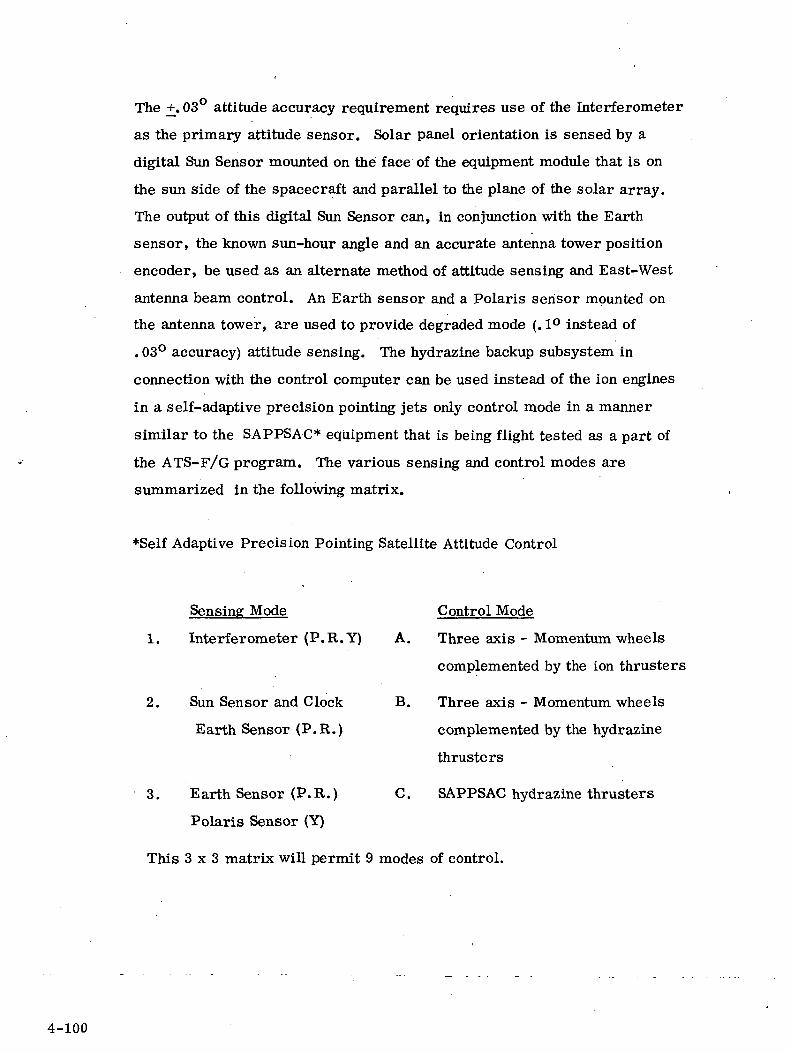
The +. 03° attitude accuracy requirement requires use of the Interferometer
as the primary attitude sensor. Solar panel orientation is sensed by a
digital Sun Sensor mounted on the face of the equipment module that is on
the sun side of the spacecraft and parallel to the plane of the solar array.
The output of this digital Sun Sensor can, in conjunction with the Earth
sensor, the known sun-hour angle and an accurate antenna tower position
encoder, be used as an alternate method of attitude sensing and East-West
antenna beam control. An Earth sensor and a Polaris sensor mounted on
the antenna tower, are used to provide degraded mode (. 1° instead of
. 03° accuracy) attitude sensing. The hydrazine backup subsystem in
connection with the control computer can be used instead of the ion engines
in a self-adaptive precision pointing jets only control mode in a manner
similar to the SAPPSAC* equipment that is being flight tested as a part of
the ATS-F/G program. The various sensing and control modes are
summarized in the following matrix.
*Self Adaptive Precision Pointing Satellite Attitude Control
Sensing Mode Control Mode
1. Interferometer (P. R.Y) A. Three axis - Momentum wheels
complemented by the ion thrusters
2. Sun Sensor and Clock B. Three axis - Momentum wheels
Earth Sensor (P.R.) complemented by the hydrazine
thrusters
3. Earth Sensor (P.R.) C. SAPPSAC hydrazine thrusters
Polaris Sensor (Y)
This 3x3 matrix will permit 9 modes of control.
4-100
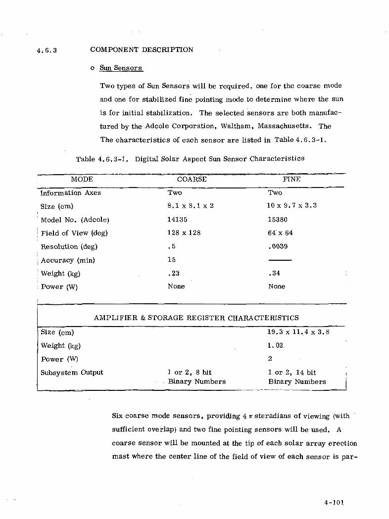
4.6.3 COMPONENT DESCRIPTION
o Sun Sensors
Two types of Sun Sensors will be required, one for the coarse mode
and one for stabilized fine pointing mode to determine where the sun
is for initial stabilization. The selected sensors are both manufac-
tured by the Adcole Corporation, Waltham, Massachusetts. The
The characteristics of each sensor are listed in Table 4.6.3-1.
Table 4.6.3-1. Digital Solar Aspect Sun Sensor Characteristics
MODE COARSE FINE
Information Axes
Size (cm)
Model No. (Adcole)
Field of View (deg)
Resolution (deg)
Accuracy (min)
Weight (kg)
Power (W)
Two
8.1 x 8.1 x 2
14135
128 x128
.5
15
.23
None
Two
10 x 9.7 x 3.3
15380
64 x 64
.0039
.34
None
AMPLIFIER & STORAGE REGISTER CHARACTERISTICS
Size (cm)
Weight (kg)
Power (W)
Subsystem Output 1 or 2, 8 bitBinary Numbers
19.3 x 11.4 x 3.S
1.02
2
1 or 2, 14 bitBinary Numbers
Six coarse mode sensors, providing 4 if steradians of viewing (with
sufficient overlap) and two fine pointing sensors will be used. A
coarse sensor will be mounted at the tip of each solar array erection
mast where the center line of the field of view of each sensor is par-
4-101
allel to the centerline of the masts. Additionally, a coarse sensor will
be mounted (1) on the top of the reflector at its center of rotation
(when not deployed) and directed in the Northern direction, (2) on the
south face and directed in the Southern direction, (3) such that its
FOV is in the Xi direction, and (4) with its FOV in the -Xj direction.
Redundancy is not considered necessary for the coarse mode sensors
because of the relatively short life requirement and their inherent high
reliability.
A common electronic box will be used as an amplifier and storage
register since signals from only one sensor at a time will be processed.
Selected circuit redundancy will be employed to meet the long life re-
quirements. The characteristics of the electronic box are also tabulated.
• Interferometer
The spacecraft interferometer consists of the following components
a. Antenna Array Assembly
b. Receiver/Converter Assembly
The interferometer is a precision, wide field-of-view attitude sensor
for the spacecraft attitude control system.
It measures the phase difference of signals received at paired antenna
elements and converts this information into digital data, which is
then related to spacecraft attitude.
The interferometer can be used as a three axis sensor. The inter-
ferometer accuracy requirements are specified in the following:
a. Attitude Determination - The space angle
between the line-of-sight from the spacecraft
(SC) to the ground emitter and the SC apparent
yaw (Z)-axis shall be measured with an ac-
4-102
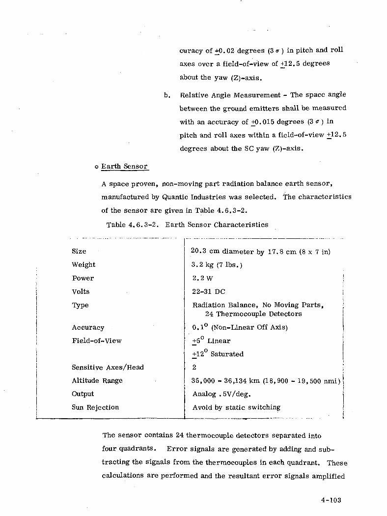
curacy of +0.02 degrees (3 a ) in pitch and roll
axes over a field-of-view of +12.5 degrees
about the yaw (Z)-axis.
b. Relative Angle Measurement - The space angle
between the ground emitters shall be measured
with an accuracy of +0.015 degrees (3 a ) in
pitch and roll axes within a field-of-view +12.5
degrees about the SC yaw (Z)-axis.
o Earth Sensor
A space proven, non-moving part radiation balance earth sensor,
manufactured by Quantic Industries was selected. The characteristics
of the sensor are given in Table 4.6.3-2.
Table 4.6.3-2. Earth Sensor Characteristics
Size
Weight
Power
Volts
Type
Accuracy
Field-of-View
Sensitive Axes/Head
Altitude Range
Output
Sun Rejection
20.3 cm diameter by 17.8 cm (8 x 7 in)
3.2 kg (7 Ibs.)
2.2 W
22-31 DC
Radiation Balance, No Moving Parts,24 Thermocouple Detectors
0.1° (Non-Linear Off Axis)
+_5° Linear
+12° Saturated
2
35,000 - 36,134 km (18,900 - 19,500 nmi)
Analog ,5V/deg.
Avoid by static switching
The sensor contains 24 thermocouple detectors separated into
four quadrants. Error signals are generated by adding and sub-
tracting the signals from the thermocouples in each quadrant. These
calculations are performed and the resultant error signals amplified
4-103
by a electronic circuits mounted in the detector head. The output is
and analog signal of . 5VDC/degree of error for each axis which is
linear with _+5° of offset and non-linear from ±5° to +12°. The
sensor and amplifier are saturated at +12°.
If the sun is in the field of view, a large error signal will be
generated. This signal will exceed the threshold level and the sensor
output will be commanded off by logic in the electronics. The design
of the detectors is such that the sensor will not be damaged by direct
sunlight.
Polaris Sensor
The Polaris sensor selected is a non-moving part sensor manufactured
by Honeywell and similar to the Canopus sensor used on Mars Mariner
flights 4 through 9. Such a sensor is currently specified for ATS-F/G.
The diurnal motion of Polaris (+55 arc -min) appears as an
oscillation in yaw once per orbit. To accommodate this oscillation,
the sensor is gimballed and scans electronically. The instantaneous,
scan and total field of view are given in Table 4.6.3-3 along with size,
weight and power data.
Attitude Control Computer
A small, lightweight, solid state computer made by CDC (model
469) was selected for use in the ACS. A description is given in
Table 4.6.3-4.
A redundant back-up unit could be incorporated although the MTBF
is computed to be in excess of 250, 000 hours. Alternatively, the
memory could be doubled to 32 k providing internal redundancy with
only a slight increase in weight and size over the present 16k
memory.
4-104

Table 4.6.3-3. Polaris Sensor Characteristics
Physical Characteristics
Weight Size Power
Optics/Electronics 17.6kg Optics/EleCo 29.2cm x ll.lcm x 13cmi 10 oO watts normal !
Baffle 4.4 j Baffle 18.2cm x 13.5cm x 31.6cm j 17.0 watts sun-in-field22. Okg | I (Includes LIC Power)
Performance
©Accuracy ^ 0.024°
3 sigma | 0.050° specified
o Data Resolution .0137° (analog)
o Noise Angle ( 00012° test data MM '69
3 sigma (^ 0.020° computed noise
o Output Data 9 bits (8) (bits + sign)
SCAN CHARACTERISTICS
: o Inst. F.O.V. 1° yaw x 11° roll
I o Scan. F.O.V. 3° yaw x 11° roll @1200 Hz
o Total F. O. Vc I 7° yaw x +14° roll (linear{ range)
o Roll Offset:
V 9U yaw x + 14° roll(Saturated range)
5 steps, commanded
Operating Characteristics
o Spectral Bandpass 0.3 to 0.6 microns
o Optics: Aperture 1.7 cm '
Focal Length 2.13 cm (f/1.25)
Resolution 197 lines/cm
o Detector: Image Dissector Tube,Electrostatic Deflection
o Photocathode Type: S-ll
Uniformity 20%
o Time constant < 1 s
o Operating Temperature (baseplate)+10° C to +30°C
o Vibration Environment j Mariner Mars '691 Titan IIIC
4-105
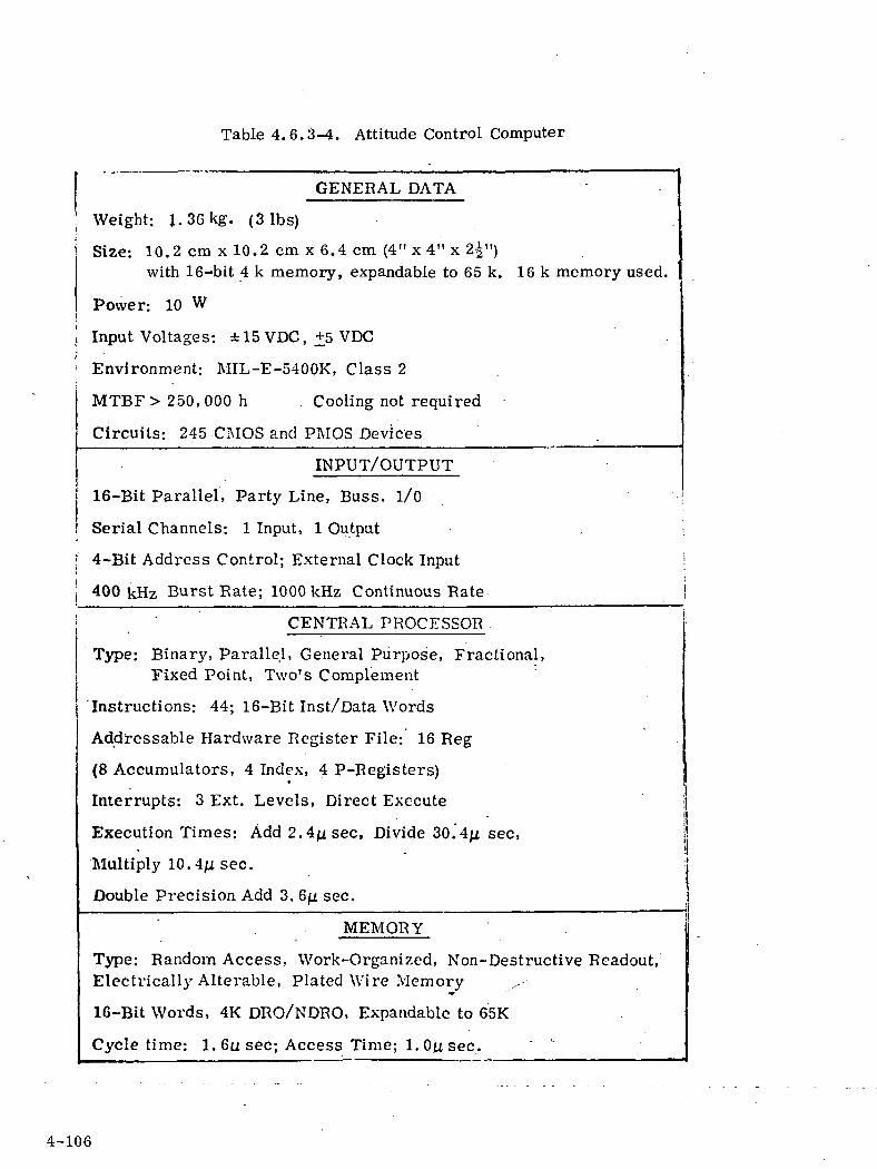
Table 4.6.3-4. Attitude Control Computer
GENERAL DATA
: Weight: 1.36kg. (3 Ibs)
| Size: 10.2 cm x 10.2 cm x 6.4 cm (4" x 4" x 2^")with 16-bit 4 k memory, expandable to 65 k. 16 k memory used.
Power: 10 W
Input Voltages: ±15 VDC, +5 VDC
Environment: MIL-E-5400K, Class 2
MTBF> 250,000 h Cooling not required
Circuits: 245 CMOS and PMOS Devices
INPUT/OUTPUT
16-Bit Parallel, Party Line, Buss. 1/0
Serial Channels: 1 Input, 1 Output .. \
I 4-Bit Address Control; External Clock Input >
I 400kHz Burst Rate; 1000 kHz Continuous Rate \
CENTRAL PROCESSOR .
Type: Binar}', Parallel, General Purpose, Fractional,Fixed Point, Two's Complement
'Instructions: 44; 16-Bit Inst/Data Words
Addressable Hardware Register File: 16 Reg
(8 Accumulators, 4 Index, 4 P-Registers)
Interrupts: 3 Ext. Levels, Direct Execute
Execution Times: Add 2.4^sec, Divide 30.4ji sec,
Multiply 10. 4^i sec.
Double Precision Add 3. GJJL sec.
MEMORY
Type: Random Access, Work-Organized, Non-Destructive Readout,Electricall}' Alterable, Plated Wire Memory
16-Bit Words, 4K DRO/NDRO, Expandable to 65K
Cycle time: 1. 6u sec; Access Time; 1. Oy sec. ' k
4-106
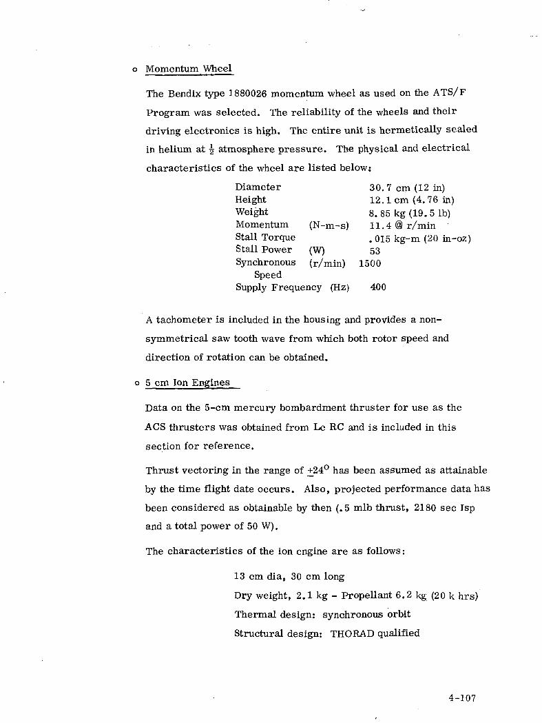
o Momentum Wheel
The Bendix type 1880026 momentum wheel as used on the ATS/F
Program was selected. The reliability of the wheels and their
driving electronics is high. The entire unit is hermetically sealed
in helium at ^ atmosphere pressure. The physical and electrical
characteristics of the wheel are listed below;
Diameter 30. 7 cm (12 in)Height 12.1 cm (4. 76 in)Weight 8. 85 kg (19.5 Ib)Momentum (N-m-s) 11.4@r/minStall Torque . 015 kg-m (20 in-oz)Stall Power (W) 53Synchronous (r/min) 1500
SpeedSupply Frequency (Hz) 400
A tachometer is included in the housing and provides a non-
symmetrical saw tooth wave from which both rotor speed and
direction of rotation can be obtained.
o 5 cm Ion Engines
Data on the 5-cm mercury bombardment thruster for use as the
ACS thrusters was obtained from Le RC and is included in this
section for reference.
Thrust vectoring in the range of +24° has been assumed as attainable
by the time flight date occurs. Also, projected performance data has
been considered as obtainable by then (.5 mlb thrust, 2180 sec Isp
and a total power of 50 W).
The characteristics of the ion engine are as follows:
13 cm dia, 30 cm long
Dry weight, 2.1 kg - Propellant 6.2 kg (20 k hrs)
Thermal design: synchronous orbit
Structural design: THORAD qualified
4-107

The development goals for the engine are summarized in the following:
Thruster input power, 60 W
Isp, 1830 sec
Overall efficiency, 26.6%
Power/Thrust, 68 w/mkg
Thrust, 0. 88 mkg
9000 hours durability design minimum
4.6.4 ACS CONFIGURATION FOR ATS-AMS I
The attitude control subsystem selected for ATS-AMS I is
three axis stabilization, using 5 cm vectorable ion thrusters mounted
at the tips of the solar array erection masts for roll-yaw axis attitude
' control and a momentum wheel for pitch axis control. The use of
the wheel is recommended because of the cyclic character of the
pitch solar disturbance torques in the I configuration (versus the
secular pitch disturbance torques in the II & in configurations).
The equipment selections for the attitude control subsystem are
determined by the previously stated pointing accuracy requirements,
the characteristics of the cyclic and secular distrubance torques
and the spacecraft mass properties. These requirements are
summarized in Table 4.6. 4-1.
Because of the required maneuvering during the spiral-out or orbit
raising portion of the mission, the tight pointing accuracy require-
ments during the synchronous altitude porition of the mission, and the
need for sensor backup over a five year life, the selection of attitude
control sensors is a particularly difficult problem. A multiple mode
4-108
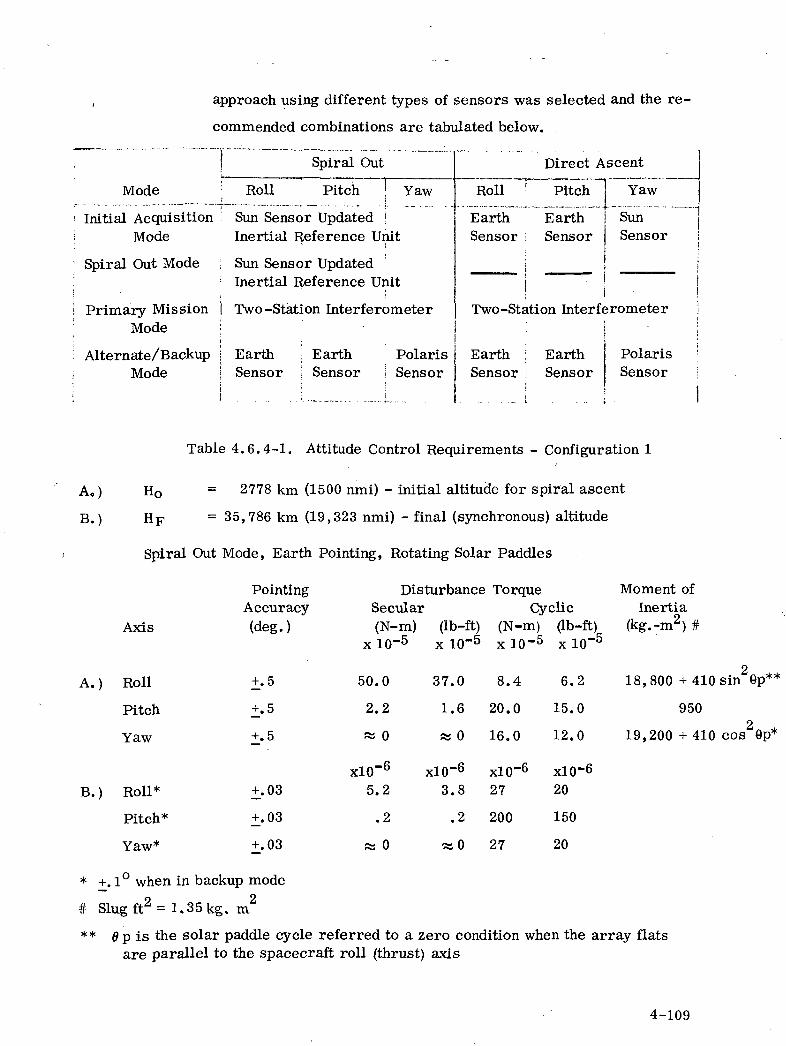
approach using different types of sensors was selected and the re-
commended combinations are tabulated below.
Mode
• Initial Acquisition1 Mode
' Spiral Out Mode
i Primary MissionMode
; Alternate/Backup; Mode;i
Spiral Out
Roll Pitch 1 YawiSun Sensor Updated !Inertia! Reference Unit
Sun Sensor UpdatedInertia! Reference Unit
Two -Station Interferometer1
-
Earth Earth PolarisSensor 1 Sensor 1 Sensor
Direct Ascent
Roll r Pitch
EarthSensor
Two-StE
EarthSensor
EarthSensor
ition Interf(
EarthSensor
Yaw
SunSensor
jrometer
PolarisSensor
B.)
Ho
HF
Table 4.6.4-1. Attitude Control Requirements - Configuration 1
2778 km (1500 nmi) - initial altitude for spiral ascent
= 35,786 km (19,323 nmi) - final (synchronous) altitude
Spiral Out Mode, Earth Pointing, Rotating Solar Paddles
Axis
Pointing Disturbance TorqueAccuracy Secular Cyclic(deg.) (N-m) (Ib-ft) (N-m) (Ib-ft)
x 10~5 x 10"5 x 10~5 x 10~5
A.)
B.)
Roll
Pitch
Yaw
Roll*
Pitch*
Yaw*
+.5
+.5
+.5
+.03
+.03
+.03
50.0
2.2
« 0
xlO"6
5.2
.2
« 0
37.0
1.6
» 0
xlO-6
3.8
.2
«0
8.4
20.0
16.0
x!0~6
27
200
27
6.2
15.0
12.0
xlO-620
150
20
Moment ofInertia
(kg.-m2) #
18,800 + 410 sin 6p**
9502
19,200 + 410 cos 9p*
* +.1° when in backup mode
# Slug ft2 = 1.35kg. m2
** 6 p is the solar paddle cycle referred to a zero condition when the array flatsare parallel to the spacecraft roll (thrust) axis
4-109
The equipment selection for ATS-AMS I is the same as for n and El
except for the following differences and additions.
1. An inertial reference unit is needed instead of a rate gyro
package, for attitude determination during the spiral-out mode
2. A momentum wheel is required for pitch control.
3. A Magnetic Control Assembly is also used at low altitudes as
an alternate means of surmounting the larger magnetic and gravity
gradient disturbance torques.
Using the sensor equipments described in the previous sections, the
initial acquisition pointing error will be less than 0.1°, the spiral
out mode pointing error will be less than 0.5°, the primary mission
mode accuracy will be less than 0.03° and the alternate mission mode
accuracy will be less than .1°.
The momentum storage capabilities of the flywheel was selected to
provide in excess of an integrated half cycle of cyclic disturbance. A
block diagram of the attitude control subsystem is given by
Figure 4.6.4-1.
As indicated by the block diagram, the roll and yaw loops are stabilized
by 5 cm mercury bombardment ion engines mounted at the tips of the
solar panels and the pitch loop is stabilized by a momentum wheel.
The momentum wheel is periodically unloaded by the auxiliary hydrazine
system which also serves as a backup for all three axes of attitude
control actuation, North-South station keeping, and East-West station
keeping.
4-110
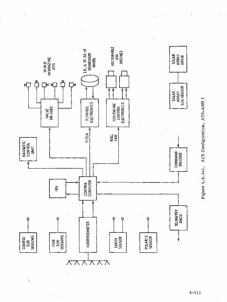
ci 6
O
'•i
£3OOK3O
CD
A A A A A A
4-111
A description of the additional equipment follows:
Inertial Reference Unit
A lightweight, strap down IRU being developed by Autonetics
Division of North America Rockwell was selected. The proposed
IRU will employ a pair of tiny electrostatically suspended, two
degree-of-freedom gyros which have wide angle pickoffs with a
4-axis precision electrostatic levitation servo, acceleration outputs
also are available. The two gyros effectively would serve as
multisensors, each performing functions of both a gyro and an
accelerometer.
The gyros use the unusual concepts of a mass unbalance modulation
pickoff and a rotor pumping scheme in which levitation servos keep
the ball running at constant speed. The small size of the gyros -
3.3 cm in diameter by 3.3 cm long - is. attributable
to the fact that they have only a single moving part and very few
parts in total. Weight of the two-axis, free rotor gyro is 0.18 kg
(0.4 lb.). The rotor itself is I cm in diameter and weighs 1 gram.
The gyro has an uncompensated random drift rate of 0.01 degrees/
hour and a steady state maximum acceleration capability of 30 g.
The full system would consist of the two inertial multisensors, an
electronics section, computer power supply, and battery, packaged
in a central support frame attachable to the spacecraft.
4-112

Initially, the attitude of each rotor is found by open-loop gyro-com-
passing. Attitude is computed 128 times per second. Direction
cosines are generated for body-to-inertial and body-to-navigation
frame transformations which are used for resolving rotor attitude
into vehicle attitude and acceleration signals into a locally
level set.•
Whenever the sinusoidal mass unbalance signal passes through
zero amplitude, a zero-crossing detector generates a pulse from
which a high-speed digital clock can measure rotor period and time
between zero crossing on successive axes. Angular readout is
found from phase angles derived from zero crossing times.
The computer accepts spin axes phase angle information and
acceleration from the inertial unit and computes velocity, position
and attitude. These data are outputted in digital form.
Momentum Wheel
The Bendix type 1823408 momentum wheel as used in the OGO
Program was selected. The wheel will be operated at a nominal
speed of 1500 r/min (at a control frequency of 800 Hz) producing
19.4 N-m-s (14.4 ft-lb-s) of angular momentum.
OGO wheels of this type have been operated continuously for over
8 years by TRW on earth and for over 6 years in space. The re-
liability of the wheels and their driving electronics is high. The en*
4-113
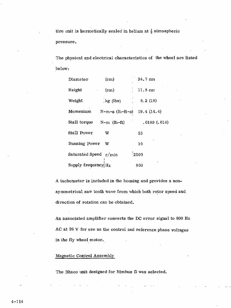
tire unit is hermetically sealed in helium at ^ atmospheric
pressure.
The physical and electrical characteristics of the wheel are listed
below:
Diameter (cm) 34.7cm
Height (cm) ; 11.8cm
Weight ',kg (Ibs) ]' 8.2(18)
Momentum N-m-s (Ib-ft-s) 19.4 (14.4)
Stall torque N-m (Ib-ft) . 0189 (. 014)
Stall Power W 53
Running Power W 10
Saturated Speed r/min 2500i
Supply frequency) Hz 800
A tachometer is included in the housing and provides a non-
symmetrical saw tooth wave from which both rotor speed and
direction of rotation can be obtained.
An associated amplifier converts the DC error signal to 800 Hz
AC at 26 V for use as the control and reference phase voltages
in the fly wheel motor.
Magnetic Control Assembly
The Ithaco unit designed for Nimbus D was selected.
4-114
The assembly consists of 3 permanent magnets mounted orthogonally
whose magnetic state can be altered by external command. The
circuits for controlling the magnets, the sensors for measuring
the dipole moment of each magnet and a magnetometer for Earth
field sensing are all included in the housing.
To fully magnetize a 10,000 pole cm (10 amp-meter^) magnet re-
quires only 1 W-s of energy. Once magnetized, no additional
power is required until the magnetic state is to be changed.
Each magnet can be magnetized to any desired state and will re-
main there indefinitely. The state of each magnet is sensed and
telemetered to the ground. The maximum field strength is less
than 100 mG at a distance of 56 cm. The unit weighs
approximately 6 Ibs (2.7 kg) and uses approximately 1 W.
This unit will not compensate for the large magnetic moment
associated with the 30 cm engines. The vector direction
of the ion engine magnetic moment is colinear with the thrust force
but can be set for either direction (either in the same sense as the
thrust force or opposite). Thus, for an added number of engines,
oa magnetic moment of approximately 35,000 pole-cm (35 amp-m )
will have to be compensated.
An additional single Ithaco magnet unit of the propermaximum
magnetic moment capacity will be required. This unit will weigh
4-115
approximately .91 kg (2 Ibs.) and will be 7.62 cm (3 in ) in dia-
meter and 30.48 cm (12 in) in length. The magnetic control
assembly magnetizing circuitry can be utilized to accomplish
the necessary alterations in magnetic state of the magnet.
A summary Table 4.6.4-2 of the equipment required for configuration I,
including weight and power, follows:
4-116

Table 4.6.4-2. ACS Components for ATS-AMS I
EQUIPMENTWEIGHT
NO'S OF UNITS kg. (Ib)
Coarse Sun Sensor 6 . 226
I
Fine Sun Sensor 2 .338
Sun Sensor Electronics
Inertial Reference Unit
Interferometer
Earth Sensor Head
Earth Sensor Electronics
Polaris Sensor
Hydrazine Subsystem
Jet Valve Drives
5 cm ion Engines(incl. fuel tanks & fuel for5 years)
Solar Array Drive & Slip Rings
Control Computer
Momentum Wheel
Wheel Electronics
Magnetic Control Unit
Hydrazine Propellant(backup for 1 year)
1 1.000
1 1.355
1 6.680
2
1
1
1
1
4
1
1
1
1
1
1
1.760
2.710
4.880
25.300
2.620
8.300
12.700
1.355
8.150
1.355
2.710
25.5
(.5) each
(.75) each
(2.2)
(3.0)
(15.1)
(3. 9) each
(6.0)
(10.8)
(56)
(5.8)
(18.4) eac
(28)
(3.0)
(18)
(3.0)
(6)
(56)
POWERW
1.0 each
2.0
10
16
15 ;
15
10
h 60 each
15
10
10
5
1
TOTAL WEIGHT: 135 kg (298 Ibs7)
4-117

4.7 ORBIT CONTROL SUBSYSTEM
4.7.1 SUBSYSTEM OPERATION AND REQUIREMENTS
The orbit control subsystem capabilities will include station acquisition
and station keeping for the ATS-AMS I, II, and HI configurations and
will include the ability to generate sufficient total impulse to raise the
orbit from approximately 1500 N. M. altitude to 19 ,323 N. M. altitude
and change the plane of the orbit inclination 28.5° for the ATS-AMS I
configuration.
The orbit will be controlled both East/West and North/South to within
an equivalent earth longitude and latitude tolerance of + . 2 . The
spacecraft will have a minimum V of 30.48m/sec (100 ft/sec) for re-
positioning, The axis of thrust will be maintained through the spacecraft
center of mass within acceptable limits.
4.1. 2 ORBIT CONTROL CONFIGURATION FOR ATS-AMS III and II
The orbit control subsystem equipment consists of a 30 cm mercury
bombardment ion engine and the backup hydrazine reaction control
subsystem. Both the ion engine and hydrazine thrusters are started
and stopped by ground command. The estimated weight and power
requirements of the 30 cm ion engine for the ATS-AMS II and III
configurations are listed in Table 4. 7. 2-1. The weight requirements
of the backup hydrazine reaction control system were previously listed
in Section 4.6.
4. 7. 3 COMPONENT DESCRIPTION
4.7.3.1 Ion Engine
For the North/South stationing, a 30 cm ion engine will be mounted on
the spacecraft +Yj Face (bottom end). The nominal thrust vector
is parallel to the Yj axis to produce motion in the -Y_ direction.
4-118
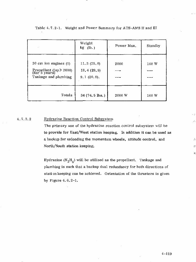
Table 4. 7. 2-1. Weight and Power Summary for ATS-AMS II and HI
30 cm ion engines (1)
Propellant (Isp> 2000)(for 5 years)Tankage and plumbing
Totals
Weightkg (lb.)
11.3 (25.0)
13.4(29.5)
9.1 (20.0).
34(74.5 Ibs.)
Power Max.
2000
2000 W
Standby
160 W
160 W
4.7 .3 .2 Hydrazine Reaction Control Subsystem
The primary use of the hydrazine reaction control subsystem will be
to provide for East/West station keeping. In addition it can be used as
a backup for unloading the momentum wheels, attitude control, and
North/South station keeping.
Hydrazine (N2H.) will be utilized as the propellant. Tankage and
plumbing is such that a backup dual redundancy for both directions of
stati on keeping can be achieved. Orientation of the thrusters is given
by Figure 4.6.2-1.
4-119
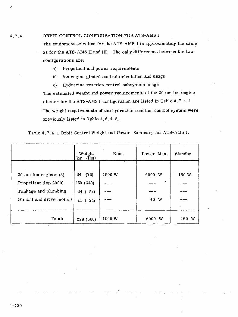
4.7.4 ORBIT CONTROL CONFIGURATION FOR ATS-AMS I
The equipment selection for the ATS-AMS I is approximately the same
as for the ATS-AMS II and IE. The only differences between the two
configurations are:
a) Propellent and power requirements
b) Ion engine gimbal control orientation and usage
c) Hydrazine reaction control subsystem usage
The estimated weight and power requirements of the 30 cm ion engine
cluster for the ATS-AMS I configuration are listed in Table 4.7.4-1
The weight requirements of the hydrazine reaction control system were
previously listed in Table 4. 6. 4-2.
Table 4. 7.4-1 Orbit Control Weight and Power Summary for ATS-AMS I.
30 cm ion engines (3)
Propellant (Isp 2000)
Tankage and plumbing
Gimbal and drive motors
Totals
Weightkg (Ibs)
34 (75)
159 (349)
24 ( 52)
11 ( 24)
228 (500).
Nom.
1500 W
1500 W
Power Max.
6000 W
40 W
6000 W
Standby
160 W i\___ :
— — —
160 W
4-120
4.7.4.1 Ion Engine Gimbal Control
For the spiral out ascent mode, a cluster of three 30 cm Hg bombard-
ment ion engines will be grouped on the spacecraft -X face (aft end).
The nominal thrust vectors are parallel to the X axis to produce motion
in the +X direction.
A two-axis gimbal system will be required permitting +15 of rotation
about axes parallel to the pitch (y) and yaw (z) axes. The motor driven
gimbals will operate at a relatively slow rate (approximately 10 rpm)
throughout their regular travel range slewing at approximately 15°/minute.
4.7.4.2 Hydrazine Reaction Control Subsystem
The primary use of the hydrazine reaction control subsystem will be
to unload the pitch momentum wheel when it is saturated. In addition,
it can be used as backup attitude control, North South station keeping,
and East-West station keeping.
Hydrazine (N?H ) will be utilized as the propellant.
4-121
4.8 THERMAL CONTROL SUBSYSTEM
Spacecraft thermal control design is dictated primarily by the
electronic and optical components' functional reliability for a five year
mission life. Due to power fluctuation and changing orbital environ-
mental conditions, the spacecraft heat rejection requirements may
vary from 300 to 5000 watts. The ATS-AMS thermal design provides
the flexibility to accommodate the variations in heat rejection rates
while maintaining the temperatures within required limits. Variable
heat rejection in a narrow radiator temperature band is achieved by
louver assemblies which vary the effective emittance of the space-
craft radiator surfaces. A typical louver assembly is capable of an
effective emittance variation from 0.14 to 0.7. Therefore, a 100%
louvered radiator generates a heat control ratio of 5. Lower turn-
down ratios are achieved by proportioning both louvered radiators
and passive radiators.
The designs of ATS-AMS III and II are similar because they are all
direct ascent, solar oriented spacecraft. Table 4.8-1 gives the
weight details.
4.8.1 ATSAMSIII
Preliminary analysis of the ATS AMS III A sun oriented spacecraft
has led to a design concept which maintains individual components within
their allowable temperature range with a minimum expenditure of cost
and weight. The spacecraft body proper contains the batteries, TT&C,
attitude control, low voltage power conditioning, experiment packages
and antenna drive. With the exception of the antenna drive this equipment
is mounted directly to the three sides of the spacecraft which do not
receive direct sunlight (Figure 4. 8.1-1). The temperature of these three
surfaces is maintained between 273°K and 308°K (32-95°F) with the aid
of thermal control louvers.
The subsolar side of the spacecraft is a mounting platform for the
high voltage solar array experiment. The .sunfacing side-contains _ _ . .
4-122
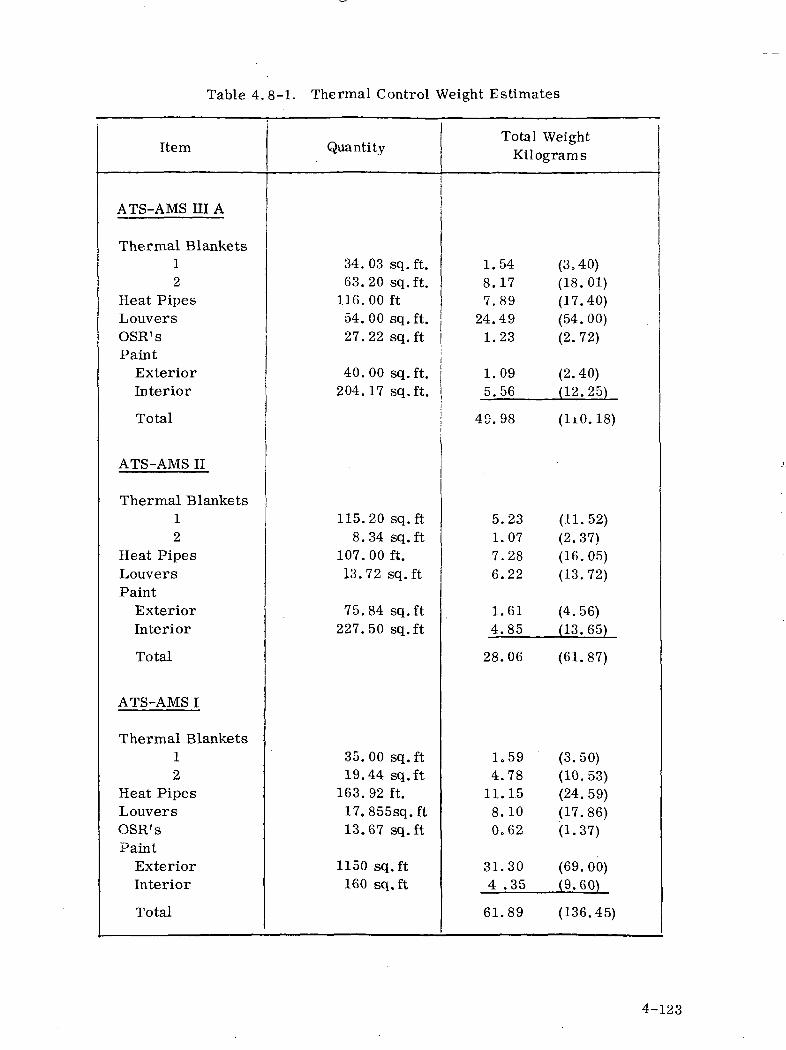
Table 4. 8-1. Thermal Control Weight Estimates
Item
ATS-AMS HI A
Thermal Blankets12
Heat PipesLouversOSR'sPaint
ExteriorInterior
Total
ATS-AMS II
Thermal Blankets12
Heat PipesLouversPaint
ExteriorInterior
Total
ATS-AMS I
Thermal Blankets12
Heat PipesLouversOSR'sPaint
ExteriorInterior
Total
Quantity
34.03 sq.ft.63.20 sq.ft.
116. 00 ft54.00 sq.ft.27.22 sq.ft
40.00 sq.ft.204.17 sq.ft.
115.20 sq.ft8.34 sq.ft
107. 00 ft.13.72 sq.ft
75.84 sq.ft227.50 sq.ft
35.00 sq.ft19.44 sq.ft
163. 92 ft.17.855sq.ft13.67 sq.ft
1150 sq.ft160 sq.ft
Total WeightKilograms
1.548.177.89
24.491.23
1.095.56
49. 98
5.231.077.286.22
1.614.85
28.06
1.594.78
11.1.58.100.62
31.304 .35
61.89
(3.40)(18.01)(17.40)(54.00)(2.72)
(2.40)(12.25)
(1x0.18)
(11.52)(2.37)(16.05)(13.72)
(4.56)(13.65)
(61.87)
(3.50)(10.53)(24. 59)(17.86)(1.37)
(69.00)(9.60)
(136.45)
4-123
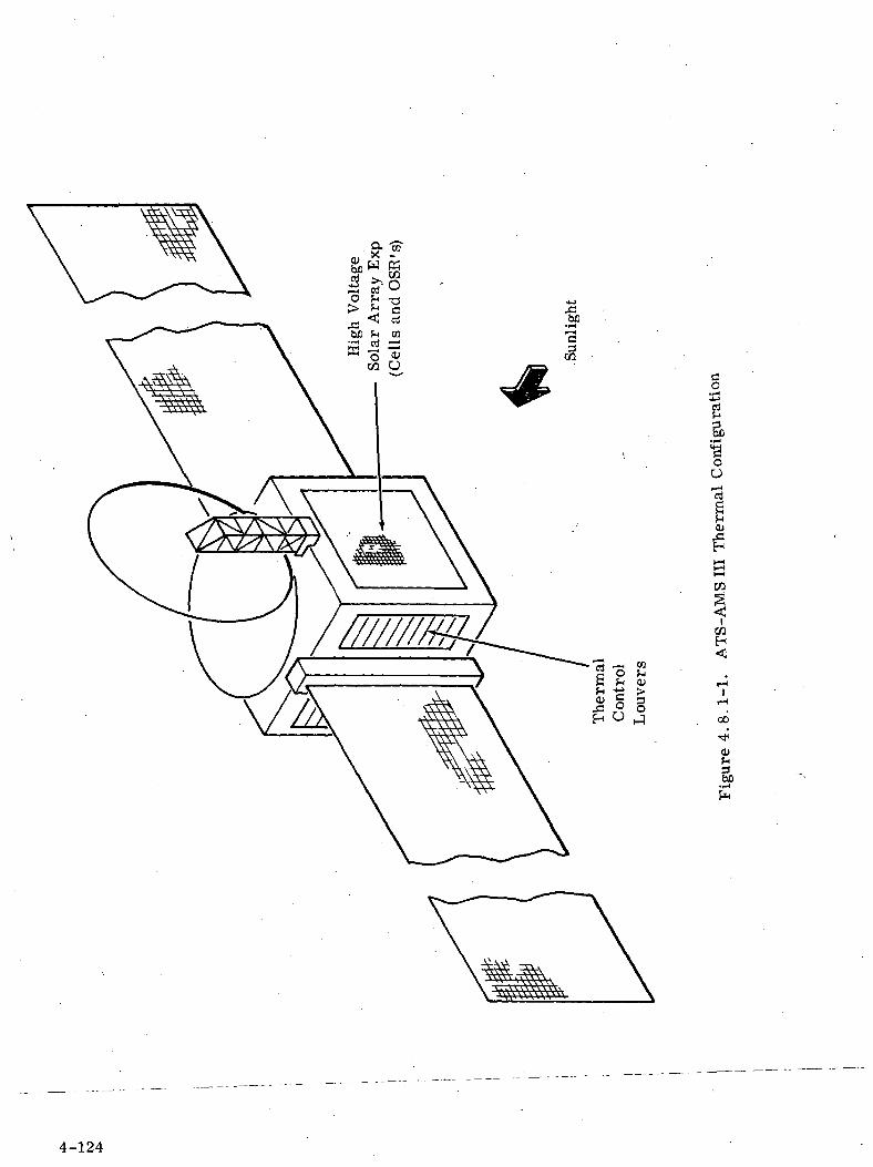
ao
rt
oO
CO
ICOH
I1-ioo
01
I
4-124
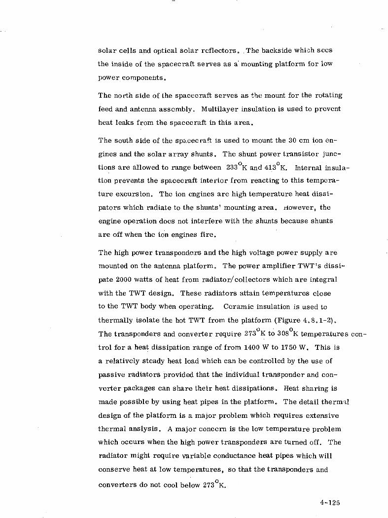
solar cells and optical solar reflectors. .The backside which sees
the inside of the spacecraft serves as a mounting platform for low
power components.
The north side of the spacecraft serves as the mount for the rotating
feed and antenna assembly. Multilayer insulation is used to prevent
heat leaks from the spacecraft in this area.
The south side of the spacecraft is used to mount the 30 cm ion en-
gines and the solar array shunts. The shunt power transistor junc-
tions are allowed to range between 233 K and 413 K. Internal insula-
tion prevents the spacecraft interior from reacting to this tempera-
ture excursion. The ion engines are high temperature heat dissi-
pators which radiate to the shunts' mounting area, riowever, the
engine operation does not interfere with the shunts because shunts
are off when the ion engines fire.
The high power transponders and the high voltage power supply are
mounted on the antenna platform. The power amplifier TWT's dissi-
pate 2000 watts of heat from radiator/collectors which are integral
with the TWT design. These radiators attain temperatures close
to the TWT body when operating. Ceramic insulation is used to
thermally isolate the hot TWT from the platform (Figure 4.8.1-2).
The transponders and converter require 273 K to 308 K temperatures con-
trol for a heat dissipation range of from 1400 W to 1750 W. This is
a relatively steady heat load which can be controlled by the use of
passive radiators provided that the individual transponder and con-
verter packages can share their heat dissipations. Heat sharing is
made possible by using heat pipes in the platform. The detail thermal
design of the platform is a major problem which requires extensive
thermal anslysis. A major concern is the low temperature problem
which occurs when the high power transponders are turned off. The
radiator might require variable conductance heat pipes which will
conserve heat at low temperatures, so that the transponders and
converters do not cool below 273 K.
4-125
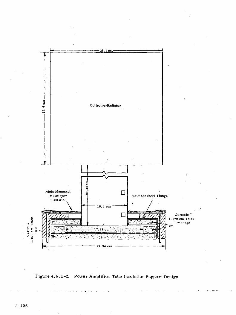
au
•25.4cm-
Collector/lladiator
Nickel/tnconnelMultilayerInsulation
•*;..;•:•'..;-.:;..'.'.:..^,17.7$cm>••..;:vv.;'•'•:•.;;:; rr
Ceramic1. 270 cm Thick
"C" Rings
Figure 4. 8.1-2. Power Amplifier Tube Insulation Support Design
4-126
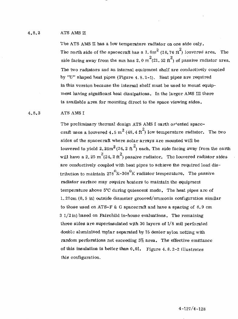
4.8.2 ATS AMS II
The ATS AMS H has a low temperature radiator on one side only.2 2The north side of the spacecraft has a 1. Om (10. 76 ft ) louvered area. The
2 2side facing away from the sun has 2. 0 m (21. 52 ft ) of passive radiator area.
The two radiators and an internal equipment shelf are conductively coupled
by "U" shaped heat pipes (Figure 4. 8. 2-1). Heat pipes are required
in this version because the internal shelf must be used to mount equip-
ment having significant heat dissipations. In the larger AMS HE there
is available area for mounting direct to the space viewing sides.
4.8.3 ATS AMS I
The preliminary thermal design ATS AMS I earth oriented space-2 2craft uses a louvered 4.5 m (48.4 ft ) low temperature radiator. The two
sides of the spacecraft where solar arrays are mounted will be
louvered to yield 2.25m2 (24. 2 ft ) each. The side facing away from the earth2 2will have a 2. 25 m (24. 2 ft ) passive radiator. The louvered radiator sides
are conductively coupled with heat pipes to achieve the required load dis-
tribution to maintain 278 K-308 K radiator temperature. The passive
radiator surface may require heaters to maintain the equipment,
temperature above 5°C during quiescent mode. The heat pipes are of
1.27cm (0.5 in) outside diameter grooved/ammonia configuration similar
to those used on ATS-F & G spacecraft and have a spacing of 8.9 cm
3 1/2 in) based on Fairchild in-house evaluations. The remaining
three sides are superinsulated with 30 layers of 1/8 mil perforated
double aluminized mylar separated by 15 denier nylon netting with
random perforations not exceeding 5% area. The effective emittance
of this insulation is better than 0.01. Figure 4. 8. 2-2 illustrates
this configuration.
4-127/4-128
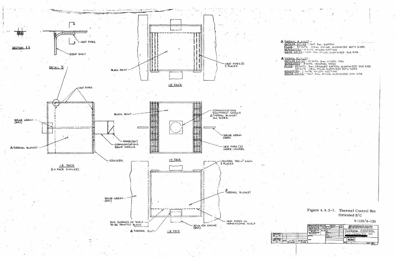
SgCTIONJ A-A
SOLAtt AB11AY —
ATUEtiMAL
HEAT PIPES (jf)2. PLACES
COMMUNICATIONSEQUIPMENT MODULE
ATUEI2.M4LALL SIDES.
COMMUNICATIONS. ^AOou\-E
-X FACE
FACE SINULAQ.
SOLAR. ABHAY
MEAT PIPES (3)UNDE.B. LOUVEOS
LOUVEQS 924 IM* E.ACU2 PLACES
ATUEB.MAL
HEAT PIPES' IMWOMEVCOM& •SHELF
.OUTSIDE CCV = a- '. S'-IT. SMIL 16APTON1
- iO S'JTS. .115 MIL MVLAQ, ALUMIMIZ£D &OTU SIDESTQZ:6 - 31 ^-TV MVLOM NETT1MG
-.ii, LL'jM'.M'.ZcD OME SIDE
OUTSIDE. CO'. ^wL- !O SUTS. .S M«. MiCU-tL FOILSE-PAaATOCS- e 5UTS. INCONEL MESHP1LLEB- 2O '-ITS. .SMIL CC.IM .LED lilAPTOM. ALUMIMIZED OME SIDE
1O SJTS. .r.Sw. MVLA2. iLUNMNllED 5OTU tjlOESSEPAOA.TCC.S- t- S-TS. 'tviYLOM METTiMGINSIDE COvH.g-- I SUT. 5 vw.. MVLA3. ALUMINIZED OME S\O£
Figure 4. 8. 2-1. Thermal Control SunOriented S/C
4-129/4-130
p~*»»
«CT
SJvuura
i. , jrT'*°0 1
b»H~~r«Ki
s=^[TUEC.MAL COMT3.OLjUV CCLtEMTED S/C
66360

-X-
Figure 4. 8. 2-2. Thermal Control SystemDelta Launched EarthOriented Spacecraft
4-131/4-132
4.9 TELEMETRY AND COMMAND SUBSYSTEM
The Telemetry and Command (T&C) subsystem provides the means
for controlling the spacecraft from the ground and for reporting to
the ground the status of key performance parameters. A block
diagram of the T&C subsystem is shown in Figure 4. 9-1 and major
T&C message characteristics are summarized in Table 4.9-1.
4.9.1 COMMAND SUBSYSTEM
The command signal is transmitted to the satellite at one of two
assigned frequencies at two independent antenna assemblies and
command receivers for space diversity reception.
The VHF antennas are capable of transmitting and receiving
circularly polarized waves and provide -3 dB gain over a j^ 17 conical
region and - 10 dB over 90% of the 4 TT Steradian sphere
surrounding the spacecraft.
Upon command verification by transmission of the received command
to the ground, an execute tone sent to the spacecraft causes the
command to be executed. A 128 Hz sine wave clock signal is extracted
by the Spacecraft Command Decoder/Distribution unit (SCDD) for
control tuning within the command subsystem. The spacecraft
recognizes four different command types: Data word, spacecraft
discrete, paddle #1 discrete and paddle #2 discrete. The received
signals are down-converted in solid state receivers by a crystal
controlled oscillator to 10.2 MHz I. F., filtered and amplified with
AGC providing demodulated command signals at reasonably constant
audio output levels to the SCDD units. The two redundant SCDD's are
digital processors which decode the command frames and distribute
them to the desired system. One of the two redundant Paddle Command
Decoder Distribution Units is energized at a time to decode the FDM
discrete commands from the SCDD.
4-133
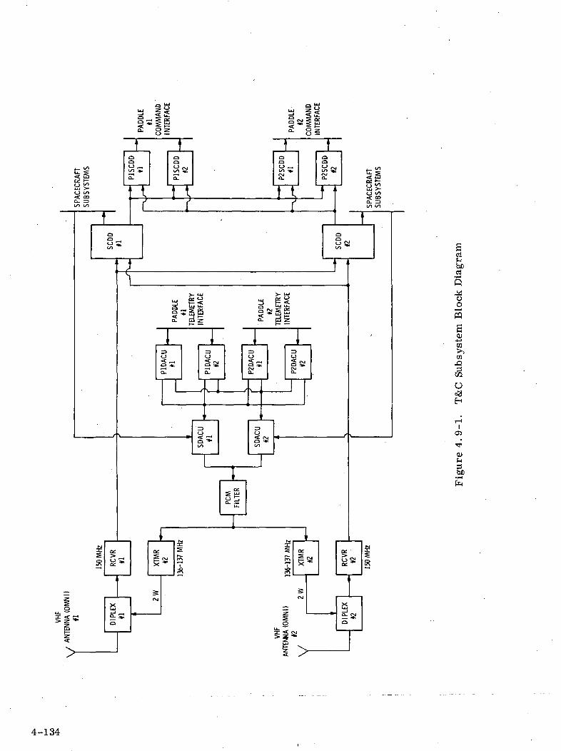
yi=«, g LU
°- 8s1
taaS32
aaKgs;
bert
S
oo
s0)
•J-JCG>>OD
Oc3H
01
^bn
4-134
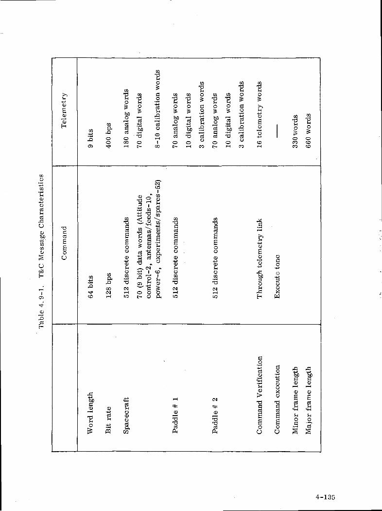
CQ
0-J~>Ortf-irt,nO0bfioj-COCQ0
Ueg
-t-i
0s"0EH
Com
man
d
CQ
•Eo
CQ Oj& C
.2 ^2 c83 0 0o ooO5 Tf iH
1
a0o0
fHo
rn 52 CQ•f^ S* ^4•F^ ^U ^J
^ 00 CM•<* CM iHCO rH IO
CQ
0
'So. -3ot-
03
ICQ
O
I—
-f^
^ff5
O
O
1CQ
, an
tenn
as/
feed
CMii— iP^1CJ
CQ
0
C
1ar— (uSoorH
1OO
LD1
CQ
s.
exp
erim
ents
/S]
Vl
CO|?H0
1
CQ
0
bJO0•3ccdOt-
ete
com
man
ds
£HoCQ
• F-l
'O
CMrHLO
CQ
CQ O
0 fl^ o
0 di
gita
l '
cali
bra
ti
rH CO
CQ
'SCQ CQ O
-E "E *o o c£ £ 2f^ ^ «P^
o ^ S| ^ 4^. ^^ro (^JD T^i
rt T3 cJ
0 0 °t- rH CO
ete
com
man
ds
£_l0ra
' w
CMTH
IO
CQ"g
O
£
6 te
lem
et
rH
30 w
ord
s
CO
CQ
•EooCO
1r— (
!i 1•4J , .3
rC f/)
bfi £3 :o c.
•3J
!H 0fi XEH H
flO• -i ^
-4-> S o n: oJ O 73
U rj oD;p1 ^ f^?. 0 «
Wor
d le
ngth
Bit r
ate
Sp
acec
raft
Pad
dle
# 1
Pad
dle
# 2
Com
man
d V
ei
Com
man
d ex
e
Min
or f
ram
e 1
t0
^H
0a
o•P— S
oJ
4-135

4.9.2 TELEMETRY SUBSYSTEM
The telemetry subsystem is in three parts: The Spacecraft Data
Acquisition unit (SDACU) and the DACU for paddle #1 and the DACU
for paddle #2. Telemetry messages are in fixed format with all
data reporting in digital form with analog information translated into
digital form by a 9-bit analog-to-digital converter in each DACU.
The Spacecraft Data Acquisition and Control Unit (SDACU) 1) moni-
tors points within the spacecraft body and performs the necessary
multiplexing, A/D conversion and formatting to make up words in
telemetry format and 2) sequences, synchronizes and controls the
Paddle Data Acquisition and Control Units (PDACU) in their genera-
tion of paddle telemetry words. This digital information is trans-
ferred serially along with spacecraft words through the SDACU for
filtering and for phase modulating a VHF carrier in two redundant
transmitters each individually commanded on-and-off by ground
command. Each VHF transmitter is solid state with a 2.0 watt
power output. The final output of each transmitter will go through
a low-pass filter to suppress spurious output signals. From the
' telemetry link analysis adequate margin exists for coherent detection
over both the -3dB gain ± 17° cone and the -10 dB gain spherical
coverage.
4.9.3 T & C PHYSICAL AND POWER CHARACTERISTICS
Table 4.9.3-1 lists for all subassemblies of the T & C subsystem
the weight and required power of each unit with estimate shown for
both spiral and direct ascent.
4-136

CO
cQJ
Sa• rH
sD1
wsa>jCO>>COX!
O
iCO
CD
3rt
£1— 1 • — •
CO ^g 5
^ A1
COH S< ^,
O
be'cu£
T3 D&rf 0
< 3— "*1O
CO ^
S s.bp'3
s-i~>t-H
CO
° ° in '
CO C5 -St* i— <
O O O O
0 0 «. 1in
CD O3 ^*
O O O O
_ «
AN
TE
NN
AS
(2)
DIP
LE
XE
R (
2)
TR
AN
SM
ITT
ER
(2
LO
W P
ASS
FIL
TE
•^ I— 1 I— 1 = , o .
ivT co co ^ 3 N ^
oj in in (M <— ' c- c-OO Tt< -^ rH ^j CO CO
I I <°. 1 I
S ^ S
•^ (M °*
J3 i i ^ S i i
L3 ^^ ^— ^^Q 0] <M Q ^ ^^
<C ^* ~~^ H <N IN^N >— 1 1— 1 (—1 «—' •— 'f*i •— ' >— ' riP 0 0 U P Qt* < < c? t-1 Q Qh Q Q ^ fe o oK '~{ N S W ""* ^r "\ Prl £J r~^ r- -\ GJ QQ
(t) H^ J M H 1-5 1-1O Q Q W Q Q Q< Q Q 0 < P QPk < < W ft < <CO PH P^ PH CO AH AH
OJ•
^
S"mmoo00
ooCO
O5
O
^^CO
CD'c~CO
CO
TO
TA
L
4-137
4. 10 STRUCTURES
The ATS-AMS HI basic structure is very similar to the ATS-F
spacecraft. The equipment module and launch vehicle interface
structure was scaled from the ATS-F counterparts. Conventional
structure is used.
The equipment/antenna sandwich platform is supported on a cylinder
which interfaces with the equipment module with two large diameter
bearings. This allows freedom of rotation and adequate load paths
for supporting the platform. The truss supported antenna reflector
and the feed system are track-mounted on the rotating platform.
Positive launch tie-downs for these components are provided.
Deployment serves to locate the feed at the antenna focal point
and to balance the spacecraft. Additionally, the honeycomb
sandwich-type, rigid reflector is deployed by a hinge system.
The solar arrays are of the flexible, roll-up type and are hoisted
and pretensioned from a graphite fiber reinforced plastic, or similar
highly efficient material, mast deployed from the side of the
spacecraft. The pretensioning is provided to give the system
adequate stiffness and therefore a frequency greater than the
control system output frequency. This "stiffening" effect may be
observed in a violin string, where the higher the tension, the higher
the pitch (frequency).
4-138


