1 © Nokia 2017
Segment Routing
Public
A tutorial• Paresh Khatri• 27-02-2017

2 © Nokia 2017
1. Introduction2. Use cases and applicability3. Deployment options4. Reference: IGP extensions for segment routing
Public
Agenda

3 © Nokia 2017
introduction
Public

4 © Nokia 2017
• Two main protocols: LDP or RSVP-TE- LDP for scale and simplicity
• extensions for fast re-route (loop-free alternates [LFAs])
- RSVP-TE for TE and FRR for some time
• To scale MPLS we enabled:- LDPoRSVP
- Seamless MPLS: Labeled-BGP with LDP
• Traffic engineering: RSVP-TE based• Services through:- BGP/IGP shortcuts, PW (T-LDP/BGP), VPLS
(LDP/BGP), IP-VPN (BGP), MVPN (BGP/mLDP/P2MP RSVP)
Public
MPLS: a historical perspective (1)
• Issues: - Traffic-engineering solutions don’t
scale when we want more granularity/dynamicity
- Remote LFA for LDP is considered too complex: requires dynamic T-LDP signaling

5 © Nokia 2017 Public
MPLS: a historical perspective (2)
LDP RSVP-TEOverview Multipoint to point Point to point
Operation Simple LSP per destination/TE-path
Dependencies Relies on IGP Relies on IGP TE
Label allocation Locally significant per node (interface)
Locally significant per node (interface)
Traffic Engineering No Yes
Scaling 1 label per node (interface)
Nx(N-1)
Fast Reroute LFA, LFA Policies, RLFA - <100% coverage
Link/Node protection (detour/facility) – 100% coverage
Multicast mLDP P2MP RSVP
IPv6 Extensions required Extensions required

6 © Nokia 2017
• Increasing network growth with granular traffic engineering (TE) requirement
• RSVP-TE is the only widely-spread solution to provide TE
• No LDP-TE available• LDP Fast ReRoute (FRR) can be used in
some parts of the network but is topology dependent
• Pros:- Source Routed protocol ; ingress Label Edge
Router (iLER) has full control to setup LSP to destination
- Presence of strong FRR and TE capabilities
• Cons:- Soft-state ; refresh mechanism required : refresh
reduction (RFC2961) aggregates messages but not # soft-states
- Mid-point state presence in network (with FRR) consumes CPU cycles and memory
Public
What problem are we trying to solve ?
SCALE RSVP-TE

7 © Nokia 2017
The primary objective for Segment Routing (SR) is source routing: the ability for a node to specify a unicast forwarding path, other than the normal shortest path, that a particular packet will traverse …
…without requiring mid-point state .
Public
Objective of Segment Routing

8 © Nokia 2017
• SPRING (Source Packet Routing In NetworkinG) Working Group addresses the following:
- IGP-based MPLS tunnels without the addition of any other signaling protocol
• The ability to tunnel services (VPN, VPLS, VPWS) from ingress PE to egress PE with or without an explicit path, and without requiring forwarding plane or control plane state in intermediate nodes.
- Fast Reroute
• Any topology, pre-computation and setup of backup path without any additional signaling.
• Support of shared-risk constraints, support of link/node protection, support of micro-loop avoidance.
Public
IETF SPRING working group

9 © Nokia 2017
• SPRING (Source Packet Routing In NetworkinG) Working Group addresses the following:
- Traffic Engineering
• The soft-state nature of RSVP-TE exposes it to scaling issues; particularly in the context of SDN where traffic differentiation may be done at a finer granularity.
• Should include loose/strict options, distributed and centralised models, disjointness, ECMP-awareness, limited (preferably zero) per-service state on midpoint and tail-end routers.
- All of this should allow incremental and selective deployment with minimal disruption
Public
IETF SPRING working group

10 © Nokia 2017
• Data plane support required:
- Leverage the existing MPLS dataplane without any modification • MPLS label stack imposition
• MPLS label operations: pop, swap, push, PHP
- Leverage the IPv6 dataplane with a new IPv6 Routing Header Type (Routing Extension Header)
Public
IETF SPRING working group

11 © Nokia 2017
• Segment Routing provides a tunneling mechanism that enables source routing.
• Paths are encoded as sequences of topological sub-paths called segments, which are advertised by link-state routing protocols (IS-IS and OSPF).
Public
Introduction to Segment Routing
Public
R1 R2 R3
R5 R6
R4SegmentSegment
Segment SegmentSegmentSegment
Segment
Segment Segment
Segment
Segment Segment
12 © Nokia 2017
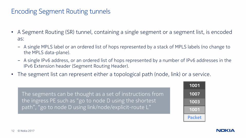
• A Segment Routing (SR) tunnel, containing a single segment or a segment list, is encoded as:- A single MPLS label or an ordered list of hops represented by a stack of MPLS labels (no change to
the MPLS data-plane).
- A single IPv6 address, or an ordered list of hops represented by a number of IPv6 addresses in the IPv6 Extension header (Segment Routing Header).
• The segment list can represent either a topological path (node, link) or a service.
Encoding Segment Routing tunnels
1001
1003
1007
1001
Packet
The segments can be thought as a set of instructions from the ingress PE such as “go to node D using the shortest path”, “go to node D using link/node/explicit-route L”

13 © Nokia 2017
• Three distinct operations:
- PUSH: the insertion of a segment at the head of the Segment list.
- NEXT: the active segment is completed; the next segment becomes active.
- CONTINUE: the active segment is not completed and hence remains active.
Public
Operations on segments

14 © Nokia 2017
• MPLS instantiation of Segment Routing aligns with the MPLS architecture defined in RFC 3031
• For each segment, the IGP advertises an identifier referred to as a Segment ID (SID). A SID is a 32-bit entity; with the MPLS label being encoded as the 20 right-most bits of the segment ID.
Segment routing with MPLS data plane (1)
Public

15 © Nokia 2017
• When Segment Routing is instantiated over the MPLS data-plane, the following actions apply :- A list of segments is represented as a stack of labels
- The active segment is the top label
- The CONTINUE operation is implemented as a SWAP operation
- The NEXT operation is implemented as a POP operation
- The PUSH operation is implemented as a PUSH operation
Segment routing with MPLS data plane (2)
Public

16 © Nokia 2017
• Segment Routing Global Block (SRGB)- SRGB is the set of local labels reserved for global
segments
- Local property of an SR node
- Using the same SRGB on all nodes within the SR domain ease operations and troubleshooting and is expected to be a deployment guideline.
Segment routing with MPLS data plane (3)Segment Routing Global Block (SRGB)
Public
MPLS Label Space
0
1048575
SRGB200000
299999

17 © Nokia 2017
Types of segmentsTaxonomy
IGP SEGMENTS BGP SEGMENTS
Prefix Segments Adjacency Segments
Node Segments
AnycastSegments
Prefix Segments Egress Peer Engineering (EPE)Segments
PeerNodeSegments
PeerSetSegments
PeerAdjSegments

18 © Nokia 2017
• EPE ; Egress Peering Engineering
• Influence how to control traffic to adjacent AS
• Signaled by BGP-LS (w/ EPE controller)
• Example: Prefix Segment in DC environment
• DC GW representation
• Signaled by BGP (in DC)
• Locally unique – each SR router in the domain can use the same space
• Typically single-hop
• Signaled by IGP
Public
Types of segments
Prefix Segment• Globally unique –
allocated from SRGB
• Typically multi-hop
• ECMP-aware shortest-path IGP route to a related prefix
• Indexing or absolute SID
• Signaled by IGP
Adjacency Segment BGP Prefix Segment BGP Peer Segment
DC
CORE/WANAS1
CORE/WANAS2
CORE/WANAS3
19 © Nokia 2017
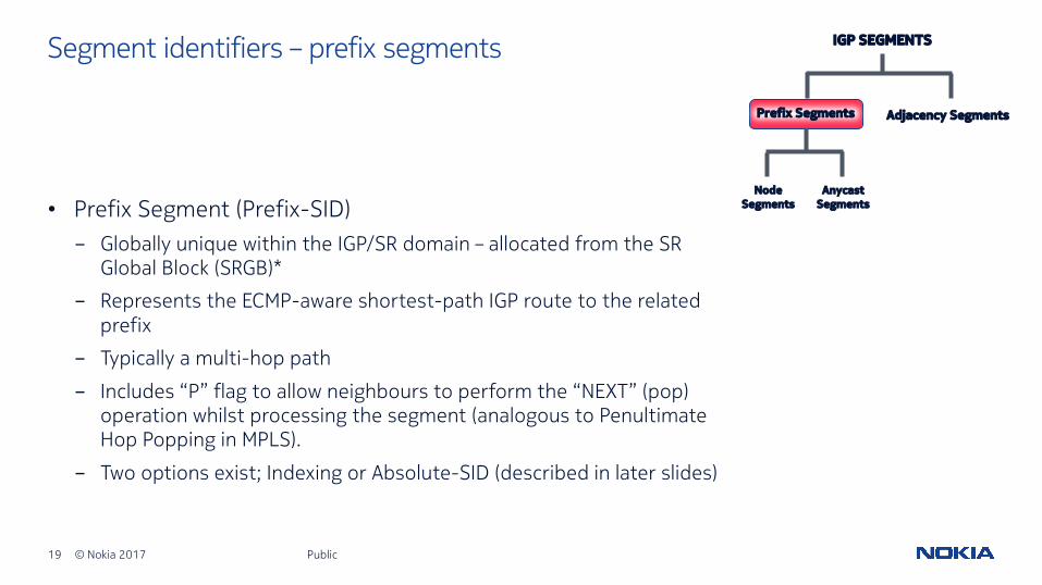
• Prefix Segment (Prefix-SID)- Globally unique within the IGP/SR domain – allocated from the SR
Global Block (SRGB)*
- Represents the ECMP-aware shortest-path IGP route to the related prefix
- Typically a multi-hop path
- Includes “P” flag to allow neighbours to perform the “NEXT” (pop) operation whilst processing the segment (analogous to Penultimate Hop Popping in MPLS).
- Two options exist; Indexing or Absolute-SID (described in later slides)
Public
Segment identifiers – prefix segments IGP SEGMENTS
Prefix Segments Adjacency Segments
Node Segments
AnycastSegments

20 © Nokia 2017
• Node Segment ID (Node-SID)- A special prefix segment used to identify a specific router
(loopback/system address).
- Identified by “N” flag being set in advertised segment (Prefix-SID Sub-TLV).
- Represents the ECMP-aware shortest-path IGP route to the specified node.
Public
Segment identifiers – node segments IGP SEGMENTS
Prefix Segments Adjacency Segments
Node Segments
AnycastSegments

21 © Nokia 2017
• Anycast Segment ID (Anycast-SID)- A prefix segment specifying a set of routers
- Represents the ECMP-aware shortest-path IGP route to the closest node of the “anycast set”.
- Potentially useful for coarse traffic engineering (i.e. route via plane A of dual-plane network, route via Region B of multi-region network) or node redundancy (i.e. traffic re-routes to shortest path towards any other router that is part of the “anycast set”).
Public
Segment identifiers – anycast segments IGP SEGMENTS
Prefix Segments Adjacency Segments
Node Segments
AnycastSegments

22 © Nokia 2017
• PE2 advertises Node Segment into IGP (Prefix-SID Sub-TLV Extension to IS-IS/OSPF)
• All routers in SR domain install the node segment to PE2 in the MPLS data-plane.- No RSVP and/or LDP control plane required.
- When applied to MPLS, a Segment is essentially an LSP.
Public
Example: SR tunnel with prefix-SID (node-SID) [1]
PE1 P3P1 P2
Node-SID 300Node-SID 200Node-SID 100 Node-SID 400
PE2
Node-SID 800
advertised by IGP
PHP based on p-bit setting of Prefix-SID advertised by PE2
InLabel
Out Label
Interface
800 800 To-P2InLabel
Out Label
Interface
800 800 To-P3
InLabel
Out Label
Interface
800 POP To-PE2
LFIB
LFIB
LFIB
FEV Out Label
Interface
PE2 800 To-P1
FEC to NHLFE

23 © Nokia 2017
• For traffic from PE1 to PE2, PE1 pushes on node segment {800} and uses shortest IGP path to reach PE2.
• Active segment is the top of the stack for MPLS:
Public
Example: SR tunnel with prefix-SID (node-SID) [2]
- P1 and P2 implement CONTINUE (swap) action in MPLS data-plane
- P3 implements NEXT (pop) action (based on P-bit in Prefix-SID not being set).
PE1 P3P1 P2
Node-SID 300Node-SID 200Node-SID 100 Node-SID 400
PE2
Node-SID 800
advertised by IGP
FEC PE2PUSH 800
SWAP800 to 800
SWAP800 to 800 POP 800
PHP based on p-bit setting of Prefix-SID advertised by
PE2
InLabel
Out Label
Interface
800 800 To-P2
InLabel
Out Label
Interface
800 POP To-PE2
LFIB
LFIB
LFIB
FEV Out Label
Interface
PE2 800 To-P1
FEC to NHLFE
InLabel
Out Label
Interface
800 800 To-P3

24 © Nokia 2017 Public
Example: SR tunnel with prefix-SID (node-SID) [3]
• No per-path state held in network with the exception of segment list for tunnel held at PE1.
PE1 P3P1 P2
Node-SID 300Node-SID 200Node-SID 100 Node-SID 400
PE2
Node-SID 800
advertised by IGP
FEC PE2PUSH 800
SWAP800 to 800
SWAP800 to 800 POP 800
PHP based on p-bit setting of Prefix-SID advertised by
PE2
InLabel
Out Label
Interface
800 800 To-P2
InLabel
Out Label
Interface
800 POP To-PE2
LFIB
LFIB
LFIB
FEV Out Label
Interface
PE2 800 To-P1
FEC to NHLFE
InLabel
Out Label
Interface
800 800 To-P3

25 © Nokia 2017
• The use of absolute SID values requires a single consistent SRGB on all SR routers throughout the IGP domain.
Prefix segment identifiers – absolute SIDs
• Example:- PE2 advertises MP-BGP label
910 for VPN prefix Z.
- To forward traffic to VPN prefix Z, and assuming preferred (non-ECMP) path from PE1 to PE2 is PE1-P3-P4-PE2, PE1 pushes label 910 onto bottom of stack, and label 600 (Node-SID for PE2) on top of stack.
- Label (SID) does not change hop by hop.
PE1 PE2
P1 P2
P3 P4
Node-SID600 advertised
by IGP
CE1A CE2 ZMP-BGP
Label 910
Packet
Packet
910
600
Packet
910
600Packet
910
600
Public
VPN Prefix ZPUSH 910FEC PE2PUSH 600
SWAP600 to 600
SWAP600 to 600
POP 600POP 910

26 © Nokia 2017
• Why ?- SR domain can be multi-vendor with the possibility that each vendor uses a different MPLS label
range
- Prefix SID must be globally unique within SR domain
• How ? - Indexing mechanism is required for prefix SIDs. All routers within the SR domain are expected to
configure and advertise the same prefix SID index range for a given IGP instance.
- The label value used by each router to represent a prefix ‘Z’ (= label programmed in ILM) can be local to that router by the use of an offset label, referred to as a start label :
Local Label (for Prefix SID) = (local) start-label + {Prefix SID index}
Public
Prefix SID indexing

27 © Nokia 2017
• For example, assume the SID Index Range is {1,100}.
Public
Example: Prefix SID indexing
• Each SR router in the domain defines a start point in the SRGB (start-label), and an offset label called an SID index.- SR routers sum {start-label + SID
index} to obtain a local label for a Prefix SID.
- Assuming PE2 advertises loopback 192.0.2.2/32 with a prefix index of 2:
- PE2’s SID for itself is {1010+2}= 1012
- P4’s SID for PE2 is {1020+2}= 1022
PE1 PE2
P1 P2
P3 P4
CE1A CE2 ZMP-BGP
Label 910
Packet
Packet
910
1032
Packet
910
1022Packet
910
1012
VPN Prefix ZPUSH 910FEC PE2PUSH 1032
SWAP1032 to 1022
SWAP1022 to 1012
POP 1012POP 910
- P3’s SID for PE2 is {1030+2}=1032
- PE2 advertises MP-BGP label 910 for VPN prefix Z.
Start-Label 1060
Start-Label 1040
Start-Label 1010
Start-Label 1050
Start-Label 1030
Start-Label 1020
Node-SID index 2
advertised by IGP

28 © Nokia 2017
• Adjacency Segment ID (Adj-SID)- A segment identifying an adjacency or set of adjacencies that must
be in the IGP.
- Segment Identifier (SID) is local to the router that advertises it (every SR router in the domain can use the same segment space).
- If:• AB is the Node-SID of node N, and...
• ABC is an Adj-SID at node N to an adjacency over link L, then....
• A packet with segment list {AB, ABC} will be forwarded along the shortest-path to node N, then switched by N towards link L without any consideration of shortest-path routing.
- If the Adj-SID identifies a set of adjacencies, node N can load-balance the traffic over the members of that set.
Public
Segment identifiers – adjacency segments IGP SEGMENTS
Prefix Segments Adjacency Segments
Node Segments
AnycastSegments
29 © Nokia 2017
• All SR routers advertise Adjacency segment(s) into IGP (Adjacency-SID Sub-TLV Extension to IS-IS/OSPF).
• Adjacency segments may be of local or global significance, but only the advertising SR router installs the adjacency segment into the MPLS data-plane- From a data-path perspective, it is analogous to a label-swap to implicit-null.
• Provides for end-to-end source-routing capability where the Adjacency segments may determine the explicit hop-by-hop path through the network.
• Beware however, that label stack depth has implications on hardware.
Public
Segment identifiers – adjacency segments

30 © Nokia 2017 Public
Example: SR tunnel with adjacency segments
PE1
P3P1 P2
P4 P5
Node-SID 300Node-SID 200
Node-SID100
Node-SID 500 Node-SID 600
Node-SID 400
P6
Node-SID 700
PE2
Node-SID 800
1001
POP 1001
1007
POP 1007
1003
POP 1003
1001
Packet
POP 1001
Adj-SID 1001
Adj-SID 1007
Adj-SID 1003Adj-SID 1001
1001
1003
1007
1001
Packet
1001
1003
1007
Packet
1001
1003
Packet
1001
Packet
31 © Nokia 2017
• A combination of node and adjacency segments is also possible.• This provides the ability to exercise ECMP paths to the next specified node segment, but
enforce the use of a particular link (or links) from that node.
Public
Example: SR tunnel with node and adjacency segments

32 © Nokia 2017
• In this example, PE1 wants to traverse the link P2-P5 on the way to PE2, as it is under-utilised.
• PE1 therefore imposes the segment list {300, 1003, 800} representing the Node-SID for P2, the Adj-SID for link P2-P5, and finally the Node-SID for PE2.
Public
Example: SR tunnel with node and adjacency segments
PE1
P3P1 P2
P4 P5
Node-SID 300Node-SID 200
Node-SID100
Node-SID 500 Node-SID 600
Node-SID 400
P6Node-SID 700
PE2Node-
SID 800
POP {300, 1003}
800
SWAP 800
800
Packet
300
300 Adj-SID 1003
POP 800
800
1003
300
Packet
800
1003
300
Packet
800
Packet
800
Packet
SWAP {300, 300}

33 © Nokia 2017 Public
Comparison with LDP and RSVP-TE
LDP RSVP-TE SROverview Multipoint to point Point to point Multipoint to point
Operation Simple LSP per destination/TE-path
Simple
Dependencies Relies on IGP Relies on IGP TE Relies on IGP + offline TE
LBL allocation Local significant per node (interface)
Local significant per node (interface)
Global
Traffic Engineering No Yes yes
Scaling 1 LBL per node (interface)
Nx(N-1) 1 LBL per node/ local interface
Fast Reroute LFA, LFA Policies, RLFA - <100% coverage
Link/Node protection (detour/facility) – 100% coverage
LFA, LFA Policies, RLFA/DLFA -can get to 100% coverage (better than LDP with RLFA)
Multicast mLDP P2MP RSVP TBD
IPv6 Extensions required Extensions required Native

34 © Nokia 2017
use cases and applicability
Public

35 © Nokia 2017
• For traffic from PE1 to PE2, PE1 pushes on segment list {800} and uses shortest IGP path to reach PE2 (PE1-P1-P2-P3-PE2)- P1 and P2 install ILM
CONTINUE entry {label=800, NHLFE=label 800, Next-Hop=shortest path to PE2}
- P3 installs ILM CONTINUE or NEXT entry {label=800, POP, Next-Hop=shortest path to PE2}
Public
Use case 1: Shortest path routing (1)
PE1
P3P1 P2
P4 P5
Node-SID 300Node-SID 200
Node-SID100
Node-SID 500 Node-SID 600
Node-SID 400
P6
Node-SID 700
PE2
Node-SID 800
800800 800
SWAP 800 SWAP 800 POP 800
800
Packet
• All nodes advertise a unique node segment into the IGP.
800
Packet
800
Packet
Packet

36 © Nokia 2017
• If PE1 has ECMP>=2, and equal-cost paths to the SR tunnel tail-end exist, all equal-cost paths can be exercised:- Based on hash output, flows
m routed PE1-P1-P2-P3-PE2 with segment list {800}
- Based on hash output, flows n routed PE1-P4-P5-P6-PE2 with segment list {800}
Public
Use case 1: Shortest path routing (2)
PE1
P3P1 P2
P4 P5
Node-SID 300Node-SID 200
Node-SID100
Node-SID 500 Node-SID 600
Node-SID 400
P6
Node-SID 700
PE2
Node-SID 800
800800 800
800
800 800
ECMP
SWAP 800 SWAP 800 POP 800
800
Packet
37 © Nokia 2017
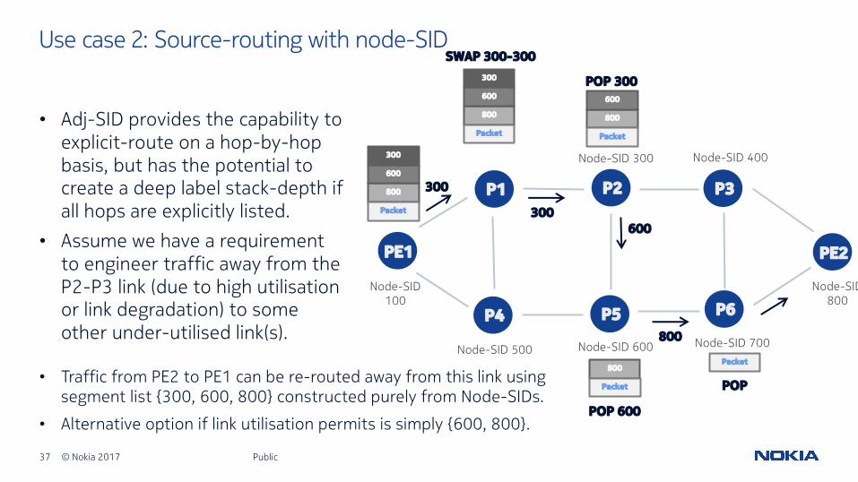
• Adj-SID provides the capability to explicit-route on a hop-by-hop basis, but has the potential to create a deep label stack-depth if all hops are explicitly listed.
• Assume we have a requirement to engineer traffic away from the P2-P3 link (due to high utilisationor link degradation) to some other under-utilised link(s).
Public
Use case 2: Source-routing with node-SID
PE1
P3P1 P2
P4 P5
Node-SID 300
Node-SID100
Node-SID 500 Node-SID 600
Node-SID 400
P6
Node-SID 700
PE2
Node-SID 800
300
300
POP 300
600
SWAP 300-300
POP 600
POP
Packet
800
800
600
300
Packet
800
600
300
Packet
800
600
Packet
800
Packet• Traffic from PE2 to PE1 can be re-routed away from this link using
segment list {300, 600, 800} constructed purely from Node-SIDs.
• Alternative option if link utilisation permits is simply {600, 800}.

38 © Nokia 2017
• Disjointness describes two (or more) services that must be completely disjoint of each other. They should not share common network infrastructure – i.e. if one fails, the other must always be active.
• Many networks employ the ‘dual-plane’ design, where inter-plane links are configured such that the route to a destination stays on that plane during a single failure scenario.
• Disjointness can broadly be achieved using Anycast segments.
Public
Use case 3: Disjointness (1)
39 © Nokia 2017
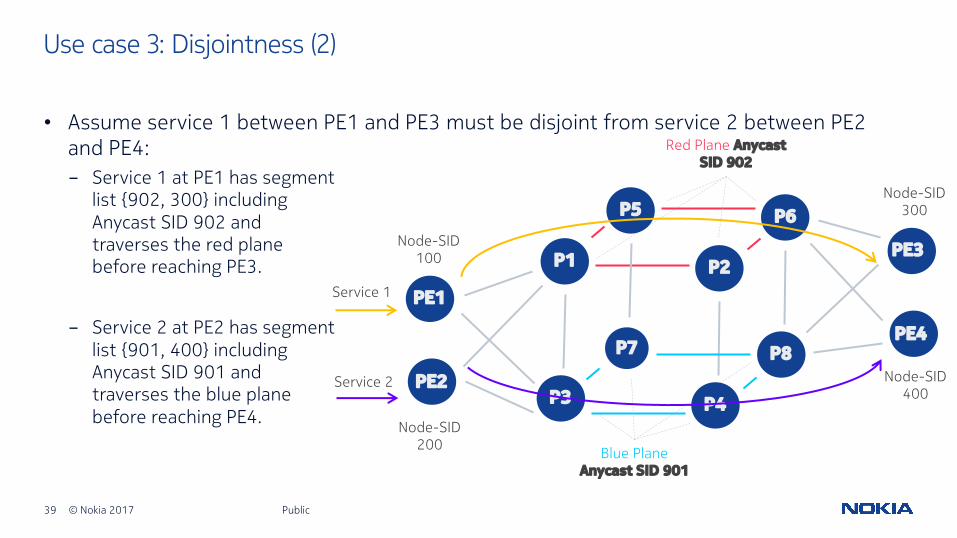
- Service 1 at PE1 has segment list {902, 300} including Anycast SID 902 and traverses the red plane before reaching PE3.
- Service 2 at PE2 has segment list {901, 400} including Anycast SID 901 and traverses the blue plane before reaching PE4.
Public
Use case 3: Disjointness (2)
• Assume service 1 between PE1 and PE3 must be disjoint from service 2 between PE2 and PE4:
PE1
P1
P3
P2
P4
P5 P6
P8PE2
PE3
PE4
Service 1
Service 2
Node-SID100
Node-SID200
Node-SID300
Node-SID400
Blue Plane Anycast SID 901
Red Plane Anycast SID 902
P7

40 © Nokia 2017
• Egress Peer Engineering defines three BGP Peering SIDs, that allow for programming of source-routed inter-domain paths; PeerNodeSID, PeerAdjSID, and PeerSetSID.
• R1 is an EPE-enabled egress router and allocates the following:- PeerNode segment for each of its
defined peers (R7, R8, and R9)
- PeerAdj segment for each recursive interface to a multi-hop peer (R9)
- PeerSet segment to a set of peers (R7 and R8) (AS200)
Use case 4: Egress peer engineering (EPE) (1)
AS 200R7
AS 300R9
R2 R1AS 100R8
EPE Controller
Node-SID 100
BGP-LSFlowSpec
Public

41 © Nokia 2017
• BGP-LS (BGP Link State) session established between EPE-enabled border router (R1) and the EPE controller:- R1 advertises PeerNode, PeerAdj, and
PeerSet SIDs using SR extensions to BGP-LS, and programmes FIB accordingly.
• EPE Controller programmes source-routes from ingress routers to EBGP peers using FlowSpec/OpenFlow; i.e.
Use case 4: Egress peer engineering (EPE) (2)
AS 200R7
AS 300R9
R2 R1AS 100R8
EPE Controller
Node-SID 100
BGP-LSFlowSpec
- 80% traffic to AS 300 with segment list {100, 1005}- 20% traffic to AS 200 with segment list {100, 1006}- Prefix <NLRI/Length> segment list {100, 1003}- Prefix <NLRI/Length> segment list {100, 1004}
Incoming Label Operation Outgoing Interface
1001 POP Link to R7
1002 POP Link to R8
1003 POP Upper link to R9
1004 POP Lower link to R9
1005 POP Load-balance on any link to R9
1006 POP Load-balance on any link to R7 or R8
Public

42 © Nokia 2017
• In this example, two adjacencies exist between P1-P2.
• Assuming capacity-based metrics are in use, the 10G link between P1 and P2 is unused for shortest path forwarding.
Use case 5: Adjacency segment load-balancing (1)
PE1 P1 P2
Node-SID 300
Node-SID 200
Node-SID100
10G PE2
Node-SID 800
40G
800800
Packet
POP 800SWAP 800-800 No load-balancing
on P1-P2 links800
Packet
800
Packet
Public

43 © Nokia 2017
• Adj-SID TLV provides the capability to load-balance across multiple adjacencies.
Use case 5: Adjacency segment load-balancing (2)
PE1 P1 P210G PE240G
Packet
POP 800
Link Adj-SID Adj-Set Weight
10G 1001 1003 1
40G 1002 1003 4
Both 1003 - -
Node-SID 200 Node-SID 300 Node-SID 800
POP 200, 1003
Weighted load-balancing on P1-P2 links
800
1003
200
Packet
800
Packet
- P1 advertises individual Adj-SIDs for the 10G link (1001) with weight 1, and 40G link (1002) with weight 4.
- P1 also advertises an Adj-SID for the adjacency set (1003)
- PE1 pushes segment list {200, 1003, 800}. Node-SID 200 gets the traffic to P1, while Adj-SID 1003 load-balances the traffic to P2 on a weighted 4:1 basis.
Public

44 © Nokia 2017
• Traffic Engineering information made available to CSPF for RSVP-TE based LSPs can also be made available to SR tunnels- Includes available link bandwidth, admin-groups, shared-risk link groups (SRLGs) etc.
Use case 6: Distributed cspf-based traffic engineering (1)
• In the example topology, assume that link P1-P2 is in SRLG 1. - The SRLG information is
flooded into IS-IS (RFC 4874) or OSPF (RFC 4203).
PE1 P1 P2
P3 P4
Node-SID 300Node-SID 200Node-SID 100
Node-SID 500 Node-SID 600
PE2
Node-SID 800
SRLG 1
Public
45 © Nokia 2017
Use case 6: Distributed cspf-based traffic engineering (2)
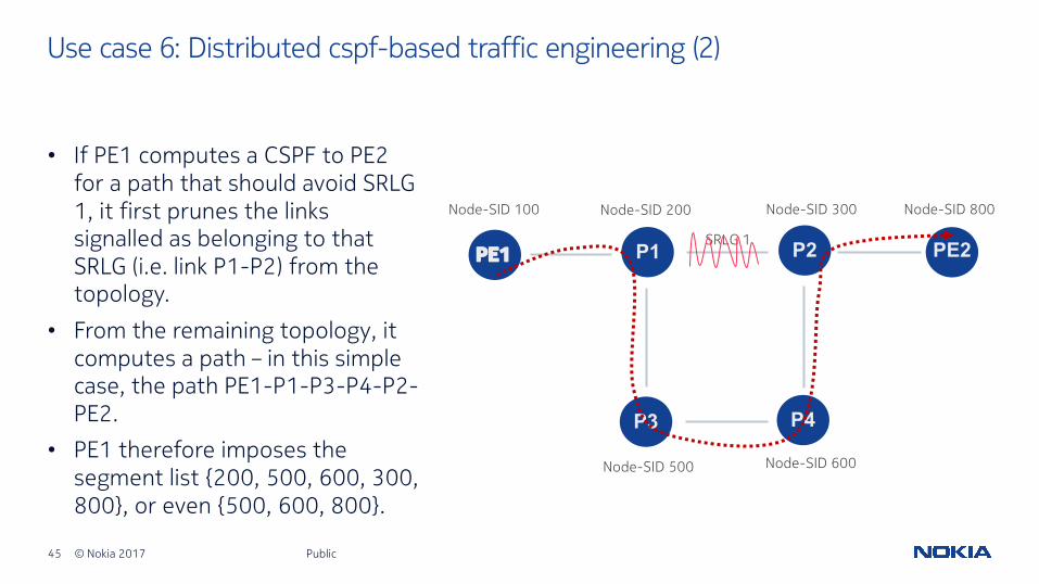
• If PE1 computes a CSPF to PE2 for a path that should avoid SRLG 1, it first prunes the links signalled as belonging to that SRLG (i.e. link P1-P2) from the topology.
• From the remaining topology, it computes a path – in this simple case, the path PE1-P1-P3-P4-P2-PE2.
• PE1 therefore imposes the segment list {200, 500, 600, 300, 800}, or even {500, 600, 800}.
PE1 P1 P2
P3 P4
Node-SID 300Node-SID 200Node-SID 100
Node-SID 500 Node-SID 600
PE2
Node-SID 800
SRLG 1
Public

46 © Nokia 2017
• SR can be seen as alternative for LDP and RSVP-TE. This means that the same scaling requirements will remain in case of an E2E MPLS coverage in a multi-area/instance domain.
• Seamless MPLS could be used to cross area or AS boundary, similar to what is available today with LDP and/or RSVP-TE. This approach has some clear advantages:- Smooth migration with existing MPLS domains
- BGP is a field-proven scalable protocol
- Non-SR nodes can still connect to a SR MPLS domain
Public
Use case 7: Seamless MPLS and segment routing (1)End-to-end scaling integrating SR/LDP/RSVP-TE

47 © Nokia 2017
Use case 7: Seamless MPLS and segment routing (2)End-to-end scaling integrating SR/LDP/RSVP-TE
Aggregation-1RSVP/LDP
Aggregation-2RSVP/LDP
CoreSegment Routing
BGP in the Core, advertising BGP LBL routes (RFC3107) with RR
BGP BGP
BGP BGP
Regions/area can still run LDP/RSVP, which allows for smooth migration… SR in the future
Access-1RSVP/LDP
BGP
BGP
Access-2RSVP/LDP
BGP
BGP
BGP peering, advertising BGP LBL routes (RFC3107)
PE1
PE2
ABR1 PE3
PE4ABR1
ABR3
ABR4
RR
Public

48 © Nokia 2017
Use case 8: Service creation with a path computation element (PCE)Co-routed service node provisioning
OSS/BSSPCE
PE1P1 P2
P4
P5
P7
P6
P8PE2
PE3
PE4
P3
1
OSS provisions diverse services on PE’sa. Type of service: VPWSb. Local attachment circuits (SAPs)c. Tunnel endpoints: Remote and
Locald. Tunnel type: Segment Routing,
RSVPe. Path constraints: Bandwidth, Co-
routed, service diversity, bi-directionality
Step 1
2
a. PE makes path computation request (PCReq), or path computation status report (PCRpt) to the PCE server
b. Note: Requires further extension to PCEP to signal path diversity with other services.
Step 2
Public

49 © Nokia 2017
Use case 8: Service creation with a path computation element (PCE) (cont.)Co-routed service node provisioning
OSS/BSSPCE
PE1P1 P2
P4
P5
P7
P6
P8PE2
PE3
PE4
P3
a. PCE monitors LSP stats and re-optimises tunnels as required, downloading new paths to PE routers (same PLSP-ID)
b. PE performs make-before-break and moves to the new path.
Step 4
12
a. PCE computes and downloads the paths for the tunnel set.
b. PEs bind service to paths
Step 33
Public

50 © Nokia 2017
Use case 9: Service creation with a path computation element (PCE)Global bandwidth optimisation
OSS/BSSPCE
PE1P1 P2
P4
P5
P7
P6
P8PE2
PE3
PE4
P3
1
OSS provisions parallel infrastructure tunnels between a pair of PE nodesa. Type of service: VPRN, VPLS VPWSb. Local attachment circuits (SAPs)c. Tunnel endpoints: Remote and
Locald. Tunnel type: Segment Routing,
RSVPe. Path constraints: min/max
bandwidth, diversity, admin-group
Step 1
2
a. PE makes path computation request (PCReq), or path computation status report (PCRpt) to the PCE server with path diversity constraints among the parallel set of tunnels.
b. This may use the SVEC object of PCEP (per RFC 5440) to perform a set of dependent path computation requests.
Step 2
Flow Mapper
Public

51 © Nokia 2017
Use case 9: Service creation with a path computation element (PCE)Global bandwidth optimisation
OSS/BSSPCE
PE1P1 P2
P4
P5
P7
P6
P8PE2
PE3
PE4
P3
12
a. PCE computes and downloads the path.
b. PE node informs the external flow mapper of the set of LSP-ID values created between endpoints.
Step 3
3
Flow Mapper
a. External flow mapper pushes down the mapping of flow/prefix/destination to the set of parallel tunnels using OpenFlowor XMPP.
b. PE instantiates the ACLs to map each flow to the designated LSP-ID.
Step 4
4
Public

52 © Nokia 2017
deployment options
Public

53 © Nokia 2017
• Greenfields:- Relatively straightforward
- Requires “new” software with segment routing capabilities
- Opportunity to bypass LDP or RSVP-TE altogether
- Care needs to be taken to ensure that all service types, resiliency mechanisms and traffic-engineering capabilities can be supported over segment-routed tunnels
• Existing networks:- Similar to greenfields with added
considerations:• Ability to introduce without disruption to
existing services
• Co-existence with LDP and/or RSVP-TE where deployed; “ships in the night” operation required
• Option to only build new services with segment routed tunnels, leaving existing services on existing tunnels
• Migration to an SR-only network
Public
Deployment options
Two broad categories
54 © Nokia 2017
• If an MPLS control plane client (i.e. LDP, RSVP, BGP, SR) installs forwarding entries into the MPLS data-plane, those entries need to be unique in order to function as “Ships in the Night”.
• It’s also likely that these control planes can and will co-exist. For example, LDP and SR could co-exist, where:
Public
Segment routing and LDP inter-operability
- LDP and SR are present on all routers in the network. Preference for LDP or SR for service tunnels is a local matter at the head-end. SR can also be used to enhance FRR coverage.
- SR is only present in parts of the network. LDP and SR can be interworked to provide an end-to-end tunnel and/or an FRR tunnel due to the presence of an SR Mapping Server (SRMS).
55 © Nokia 2017
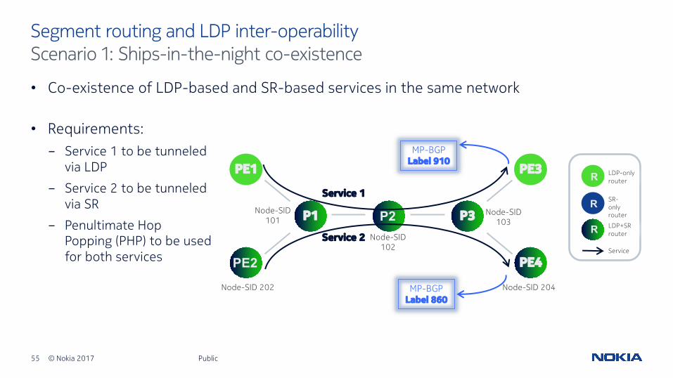
• Co-existence of LDP-based and SR-based services in the same network
Public
Segment routing and LDP inter-operabilityScenario 1: Ships-in-the-night co-existence
PE1
P2P1 P3
PE2
PE3
PE4
LDP-only router
SR-only router
Service
RR
LDP+SR routerR
RService 1
Service 2
• Requirements:- Service 1 to be tunneled
via LDP
- Service 2 to be tunneled via SR
- Penultimate Hop Popping (PHP) to be used for both services
Node-SID 202 Node-SID 204
Node-SID 101
Node-SID 102
Node-SID 103
MP-BGPLabel 910
MP-BGPLabel 860

56 © Nokia 2017 Public
Segment routing and LDP inter-operabilityScenario 1: Ships-in-the-night co-existence (cont.)
• Outcome:- Service 1 is tunneled
from PE1 to PE3 through a continuous LDP LSP traversing P1, P2 and P3.
- Service 2 is tunneled from PE2 to PE4 through a continuous SR node segment traversing P1, P2 and P3.
PE1
P2P1 P3
PE2
PE3
PE4
LDP-only router
SR-only router
Service
RR
LDP+SR routerR
RService 1
Service 2
Node-SID 202 Node-SID 204
Node-SID 101
Node-SID 102
Node-SID 103
MP-BGPLabel 910
MP-BGPLabel 860
910
423
Packet
860
204
Packet
910
700
Packet
910
819
Packet
910
Packet
860
204
Packet
860
204
Packet
860
Packet

57 © Nokia 2017
• Possible to have multiple entries in the MPLS data plane for the same prefix.
Public
Segment routing and LDP inter-operabilityScenario 1: Ships-in-the-night co-existence (cont.)
FEC IncomingLabel
OutgoingLabel
Next-Hop
192.0.2.203/32 (LDP)
423 700 P2
192.0.2.203/32 (SR) 204 204 P2
Public
PE1
P2P1 P3
PE2
PE3
PE4
LDP-only router
SR-only router
Service
RR
LDP+SR routerR
RService 1
Service 2
Node-SID 202 Node-SID 204
Node-SID 101
Node-SID 102
Node-SID 103
MP-BGPLabel 910
MP-BGPLabel 860
910
423
Packet
860
204
Packet
910
700
Packet
910
819
Packet
910
Packet
860
204
Packet
860
204
Packet
860
Packet
Node P1’s MPLS forwarding table
Loopback:192.0.2.203/32
58 © Nokia 2017
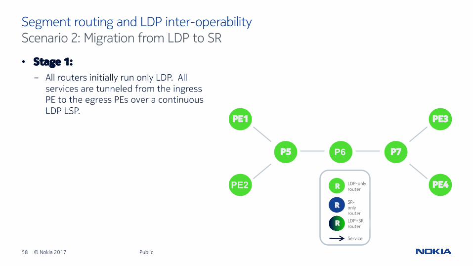
• Stage 1:- All routers initially run only LDP. All
services are tunneled from the ingress PE to the egress PEs over a continuous LDP LSP.
Public
Segment routing and LDP inter-operabilityScenario 2: Migration from LDP to SR
PE1
P6P5 P7
PE2
PE3
PE4LDP-only router
SR-only router
Service
RR
LDP+SR routerR
R

59 © Nokia 2017
• Stage 2:- All the routers are upgraded to SR. They
are configured with the SRGB range [100, 300]. PE1, PE2, PE3, PE4, P5, P6 and P7 are configured with the node segments 101, 102, 103, 104, 105, 106 and 107, respectively .
- Service traffic is still tunneled over LDP LSPs. For example, PE1 has an SR node segment to PE3 and an LDP LSP to PE3 but the LDP IP2MPLS encapsulation is preferred, by default or via configuration.
Public
Segment routing and LDP inter-operabilityScenario 2: Migration from LDP to SR (cont.)
PE1
P6P5 P7
PE2
PE3
PE4LDP-only router
SR-only router
Service
RR
LDP+SR routerR
R
Node-SID 102 Node-SID 104
Node-SID 105
Node-SID 106
Node-SID 107
Node-SID 101 Node-SID 103

60 © Nokia 2017
• Stage 3:- Local policy at PE1 is configured to prefer
SR encapsulation over LDP.
- The service from PE1 to any other PE is now riding over SR. All other service traffic is still transported over LDP LSPs.
Public
Segment routing and LDP inter-operabilityScenario 2: Migration from LDP to SR (cont.)
PE1
P6P5 P7
PE2
PE3
PE4LDP-only router
SR-only router
Service
RR
LDP+SR routerR
R
Node-SID 102 Node-SID 104
Node-SID 105
Node-SID 106
Node-SID 107
Node-SID 101 Node-SID 103
61 © Nokia 2017
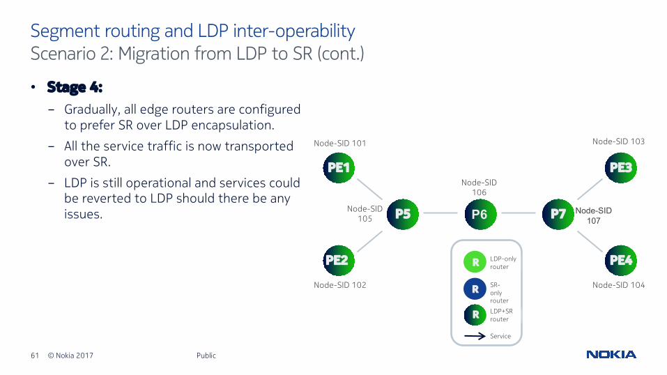
• Stage 4:- Gradually, all edge routers are configured
to prefer SR over LDP encapsulation.
- All the service traffic is now transported over SR.
- LDP is still operational and services could be reverted to LDP should there be any issues.
Public
Segment routing and LDP inter-operabilityScenario 2: Migration from LDP to SR (cont.)
PE1
P6P5 P7
PE2
PE3
PE4LDP-only router
SR-only router
Service
RR
LDP+SR routerR
R
Node-SID 102 Node-SID 104
Node-SID 105
Node-SID 106
Node-SID 107
Node-SID 101 Node-SID 103
62 © Nokia 2017
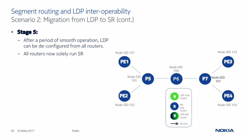
• Stage 5:- After a period of smooth operation, LDP
can be de-configured from all routers.
- All routers now solely run SR
Public
Segment routing and LDP inter-operabilityScenario 2: Migration from LDP to SR (cont.)
PE1
P6P5 P7
PE2
PE3
PE4LDP-only router
SR-only router
Service
RR
LDP+SR routerR
R
Node-SID 102 Node-SID 104
Node-SID 105
Node-SID 106
Node-SID 107
Node-SID 101 Node-SID 103

63 © Nokia 2017
• One or more Segment Routing Mapping Servers (SRMS) are used to advertise Node-SIDs on behalf of non-SR routers. For example, R4 advertises Node-SIDs 201, and 202, respectively for the LDP-only routers A, and B.
Public
Segment routing and LDP inter-operabilityScenario 3: Mix of SR-only and LDP-only routers (SR and LDP inter-working)
- A forwards to R1 using conventional LDP. R1 does not have a LDP label binding for its next-hop R2, but does have an SR Node-SID, so it swaps its local LDP-label for FEC B to Node-SID 202 and forwards to R2.
- R3 knows that B is not SR-capable (as B did not advertise SR capability in ISIS/OSPF), so R3 swaps Node-SID 202 for LDP FEC B.
BA
Node-SID 103
Node-SID 104
Mapping Server (SRMS)
Node-SID 102Node-SID 101
Swap LDP FEC B to Node-SID 202
R1 R2 R3
R4 R5
Swap Node-SID 202 to LDP FEC
B
LDP binding to B Next-Hop=R1
Node-SID 105
Node Node Segment
A 201
B 202
LDP-only router
SR-only router
Service
RR
LDP+SR routerR
R

64 © Nokia 2017
• A similar methodology to LDP-SR interworking can be used to provide FRR coverage:- Potential for increased
coverage where SR is present only in parts of the network.
- Full coverage if SR is present on all routers in the network (in which case no Mapping Server is required).
Public
Segment routing and LDP inter-workingScenario 4: Using SR to provide LDP fast reroute
Node-SID 101
A
301010
10
10 10
10
R2 CB R1
R4 R5 R6 R7
R3
Node-SID 103
Node-SID 104 Node-SID 105 Node-SID 106 Node-SID 107
Mapping Server (SRMS)
Node-SID 102
10
LDPFEC
Incoming Label
Outgoing Label
Outgoing Next-Hop
B Advertised by R2
Advertised by R1 R1
C Advertised by R2
Advertised by R3 R3
Node Node Segment
A 201
B 202
C 203
LDP-only router
SR-only router
Service 1 (A-B)
RR
LDP+SR routerR
R
Service 2 (A-C)

65 © Nokia 2017
• In the example shown, LDP is used throughout the network, and SR has only partial coverage (routers R1-R7).
Public
Segment routing and LDP inter-workingScenario 4: Using SR to provide LDP fast reroute (cont.)
Node-SID 101
A
301010
10
10 10
10
R2 CB R1
R4 R5 R6 R7
R3
Node-SID 103
Node-SID 104 Node-SID 105 Node-SID 106 Node-SID 107
Mapping Server (SRMS)
Node-SID 102
10
LDPFEC
Incoming Label
Outgoing Label
Outgoing Next-Hop
B Advertised by R2
Advertised by R1 R1
C Advertised by R2
Advertised by R3 R3
Node Node Segment
A 201
B 202
C 203
LDP-only router
SR-only router
Service 1 (A-B)
RR
LDP+SR routerR
R
Service 2 (A-C)
- R4 is SRMS and advertises Node-SID 201, 202, 203 respectively for the LDP-only routers A, B, and C.
- Router A has services to B and C. LDP is the preferred transport protocol and is used by the head-end, router A (local decision).
- Objective is to protect link R2-R1 for service 1, and link R2-R3 for service 2.

66 © Nokia 2017
• Protecting service 1- Objective is to protect link
R2-R1 with a Loop-Free Alternate (LFA) for B (Service 1).
- Routers R1-R7 advertise Node-SID and Adjacency-SIDs for its IGP adjacencies. R4 is acting as Mapping Server for A, B, and C.
- In steady-state, LDP is used as the preferred transport tunnel for Service 1 (A-R2-R1-B).
Public
Segment routing and LDP inter-workingScenario 4: Using SR to provide LDP fast reroute (cont.)
Node-SID 101
A
301010
10
10 10
10
R2 CB R1
R4 R5 R6 R7
R3
Node-SID 103
Node-SID 104 Node-SID 105 Node-SID 106 Node-SID 107
Node-SID 102
10
Node Node Segment
A 201
B 202
C 203
LDP-only router
SR-only router
Service 1 (A-B)
RR
LDP+SR routerR
R
Service 2 (A-C)
Dest. Incoming Label Outgoing Label Outgoing
Next-Hop
Backup Outgoing
Label
Backup Outgoing Next-Hop
B Advertised by R2
Advertised by R1 R1 202
(B N-SID)
Repair tunnel: Node-SID R4 Next-Hop R5
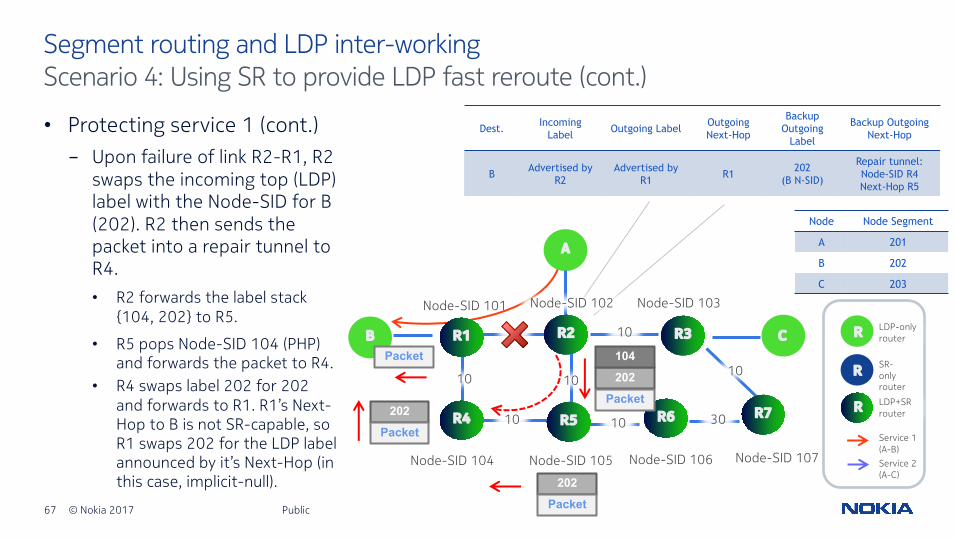
67 © Nokia 2017
• Protecting service 1 (cont.)- Upon failure of link R2-R1, R2
swaps the incoming top (LDP) label with the Node-SID for B (202). R2 then sends the packet into a repair tunnel to R4. • R2 forwards the label stack
{104, 202} to R5.
• R5 pops Node-SID 104 (PHP) and forwards the packet to R4.
Public
Segment routing and LDP inter-workingScenario 4: Using SR to provide LDP fast reroute (cont.)
Node-SID 101
A
301010
10
10 10
10
R2 CB R1
R4 R5 R6 R7
R3
Node-SID 103
Node-SID 104 Node-SID 105 Node-SID 106 Node-SID 107
Node-SID 102
10
Node Node Segment
A 201
B 202
C 203
LDP-only router
SR-only router
Service 1 (A-B)
RR
LDP+SR routerR
R
Service 2 (A-C)
Dest. Incoming Label Outgoing Label Outgoing
Next-Hop
Backup Outgoing
Label
Backup Outgoing Next-Hop
B Advertised by R2
Advertised by R1 R1 202
(B N-SID)
Repair tunnel: Node-SID R4 Next-Hop R5
Packet
202104
Packet202
Packet
202Packet
• R4 swaps label 202 for 202 and forwards to R1. R1’s Next-Hop to B is not SR-capable, so R1 swaps 202 for the LDP label announced by it’s Next-Hop (in this case, implicit-null).
68 © Nokia 2017
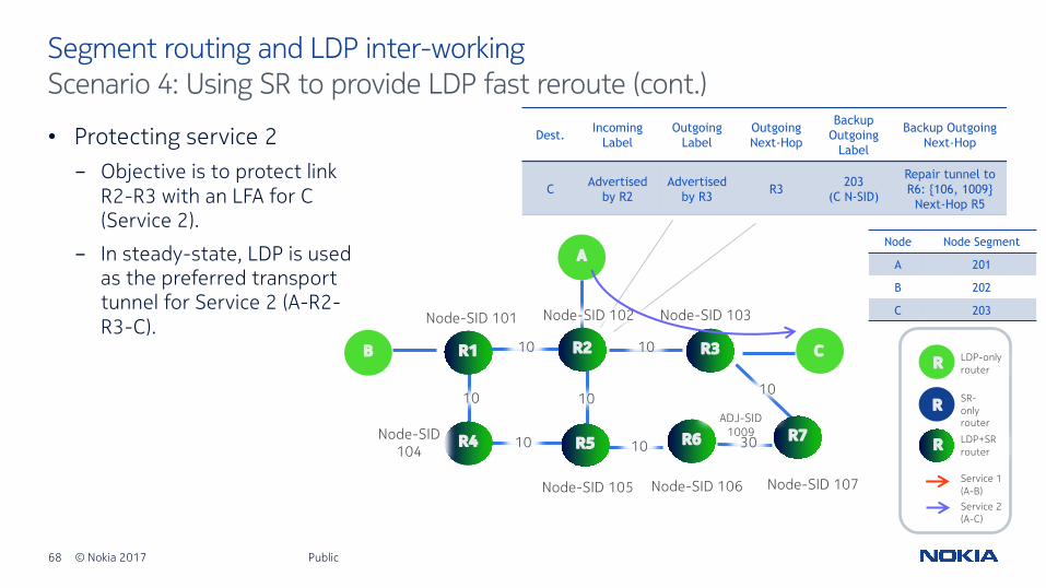
• Protecting service 2- Objective is to protect link
R2-R3 with an LFA for C (Service 2).
- In steady-state, LDP is used as the preferred transport tunnel for Service 2 (A-R2-R3-C).
Public
Segment routing and LDP inter-workingScenario 4: Using SR to provide LDP fast reroute (cont.)
Node-SID 101
A
301010
10
10 10
10
R2 CB R1
R4 R5 R6 R7
R3
Node-SID 103
Node-SID 105 Node-SID 106 Node-SID 107
Node-SID 102
10
Node Node Segment
A 201
B 202
C 203
LDP-only router
SR-only router
Service 1 (A-B)
RR
LDP+SR routerR
R
Service 2 (A-C)
Dest. Incoming Label
Outgoing Label
Outgoing Next-Hop
Backup Outgoing
Label
Backup Outgoing Next-Hop
C Advertised by R2
Advertised by R3 R3 203
(C N-SID)
Repair tunnel to R6: {106, 1009}
Next-Hop R5
Node-SID 104
ADJ-SID 1009
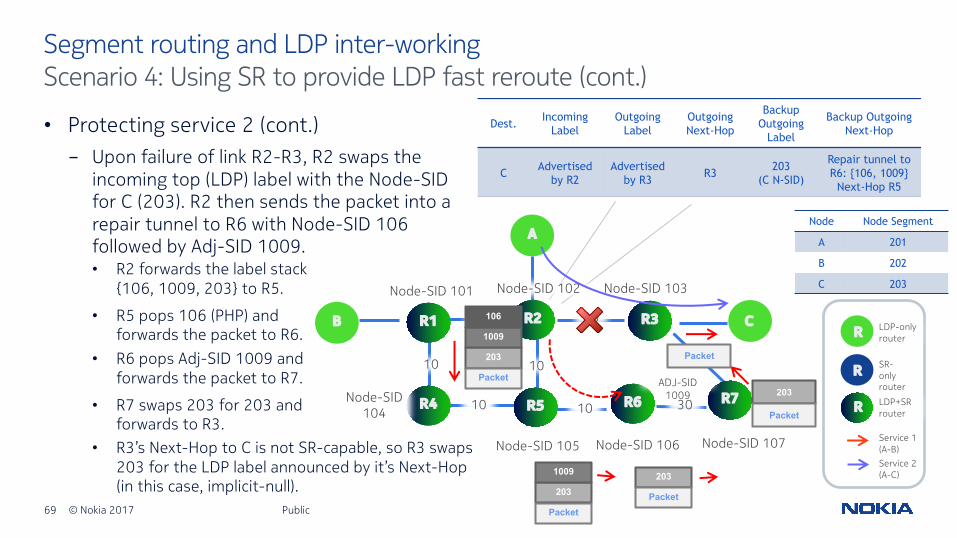
69 © Nokia 2017
• Protecting service 2 (cont.)- Upon failure of link R2-R3, R2 swaps the
incoming top (LDP) label with the Node-SID for C (203). R2 then sends the packet into a repair tunnel to R6 with Node-SID 106 followed by Adj-SID 1009.
Public
Segment routing and LDP inter-workingScenario 4: Using SR to provide LDP fast reroute (cont.)
Node-SID 101
A
301010
10
10 10
10
R2 CB R1
R4 R5 R6 R7
R3
Node-SID 103
Node-SID 105 Node-SID 106 Node-SID 107
Node-SID 102
10
Node Node Segment
A 201
B 202
C 203
LDP-only router
SR-only router
Service 1 (A-B)
RR
LDP+SR routerR
R
Service 2 (A-C)
Dest. Incoming Label
Outgoing Label
Outgoing Next-Hop
Backup Outgoing
Label
Backup Outgoing Next-Hop
C Advertised by R2
Advertised by R3 R3 203
(C N-SID)
Repair tunnel to R6: {106, 1009}
Next-Hop R5
Packet203
1009
106
Packet
203
1009
Packet
203
Packet
203
Packet
• R2 forwards the label stack {106, 1009, 203} to R5.
• R5 pops 106 (PHP) and forwards the packet to R6.
• R6 pops Adj-SID 1009 and forwards the packet to R7.
• R7 swaps 203 for 203 and forwards to R3.
• R3’s Next-Hop to C is not SR-capable, so R3 swaps 203 for the LDP label announced by it’s Next-Hop (in this case, implicit-null).
Node-SID 104
ADJ-SID 1009

70 © Nokia 2017
igp extensions for segment routing
Public

71 © Nokia 2017
• IS-IS and OSPF both have “Router Information” extensions to advertise optional capabilities:- Opaque “Router Information” LSA in OSPF (RFC 4970) carrying Router Informational Capability TLV.
- Capability TLV (TLV-242) in IS-IS (RFC 4971) with optional Sub-TLVs.
• Intended to indicate capabilities such as Graceful Restart, TE, OSPF stub, IS-IS mesh group, etc.
• Flooding scope:- IS-IS: across domain, and may be leaked between levels (indicated by “S” flag).
- OSPF: link-scoped (type 9), area-scoped (type 10), or AS-scoped (type 11).
Public
Router informationSegment routing capability

72 © Nokia 2017
• Extended to indicate support for Segment Routing:- SR-Capabilities Sub-TLV (IS-IS) or
SID/Label Range TLV (OSPF)• Used to indicate label range and start
number.
- SR-Algorithm Sub-TLV used to advertise algorithms used for path calculation (SPF, CSPF etc). • Two values currently defined:
- SPF (value 0)
- Strict SFP (value 1)
Public
Router informationSegment routing capability
Type Length Flags Range
Range (cont.)
I V
SID/Label Sub-TLV (variable)
Range Size
Type
Reserved
Length
Sub-TLVs (variable)
OSPF SID/Label Range TLV
(Carries a SID/Label Sub-TLV to represent first SID/Label from the advertised range).
IS-IS SR-Capabilities Sub-TLVI flag: IPv4 capableV flag: IPv6 capable

73 © Nokia 2017
• Introduction of Prefix-SID SUB-TLV, which may be present in either:- TLV-135 (IPv4), TLV-235 (MT-IPv4)- TLV-236 (IPv6), TLV-237 (MT-IPv6)
• SID/Index/Label contains either:- A 32-bit index defining the offset
in the SID/Label space advertised by this router
- A 24-bit label, where the 20 rightmost bits are used for encoding the label value
- A variable length SID (i.e. An IPv6 address SID)
Public
IS-IS extensionsPrefix-SID sub-TLV
Type Length Flags Algorithm
SID/Index/Label (variable)
R N P E V L
Flag Meaning
R-flagRe-advertisement flag. If set, the prefix to which this Prefix-SIDis attached has been propagated by the router either from another level (L2 to L1 or vice-versa) or from redistribution.
N-flag
Node-SID flag. If set, the Prefix-SID refers to the router identified by the prefix (router loopback/system address). The prefix to which the SID is attached must have a prefix length of /32 (IPv4) or /128 (IPv6)
P-flag No-PHP flag. If set, the penultimate hop must not pop the Prefix-SID before delivering the packet to the advertising router.
E-flagExplicit-Null flag. If set, any upstream neighbour of the Prefix-SID originator must replace the Prefix-SID with a Prefix-SID having an Explicit-Null value before forwarding the packet.
V-flag Value flag. If set, the Prefix-SID carries an absolute value (instead of an index)
L-flag Local flag. If set, the value/index carried by the Prefix-SID has local significance.
74 © Nokia 2017
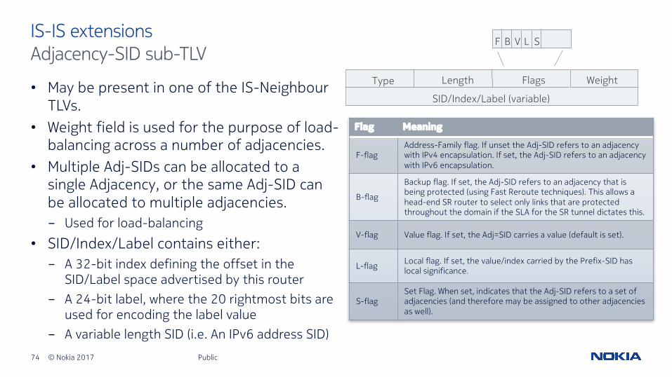
• May be present in one of the IS-Neighbour TLVs.
• Weight field is used for the purpose of load-balancing across a number of adjacencies.
• Multiple Adj-SIDs can be allocated to a single Adjacency, or the same Adj-SID can be allocated to multiple adjacencies.- Used for load-balancing
• SID/Index/Label contains either:- A 32-bit index defining the offset in the
SID/Label space advertised by this router - A 24-bit label, where the 20 rightmost bits are
used for encoding the label value- A variable length SID (i.e. An IPv6 address SID)
Public
IS-IS extensionsAdjacency-SID sub-TLV
Flag Meaning
F-flagAddress-Family flag. If unset the Adj-SID refers to an adjacency with IPv4 encapsulation. If set, the Adj-SID refers to an adjacency with IPv6 encapsulation.
B-flag
Backup flag. If set, the Adj-SID refers to an adjacency that is being protected (using Fast Reroute techniques). This allows a head-end SR router to select only links that are protected throughout the domain if the SLA for the SR tunnel dictates this.
V-flag Value flag. If set, the Adj=SID carries a value (default is set).
L-flag Local flag. If set, the value/index carried by the Prefix-SID has local significance.
S-flagSet Flag. When set, indicates that the Adj-SID refers to a set of adjacencies (and therefore may be assigned to other adjacencies as well).
Type Length Flags Weight
SID/Index/Label (variable)
F B V L S
75 © Nokia 2017
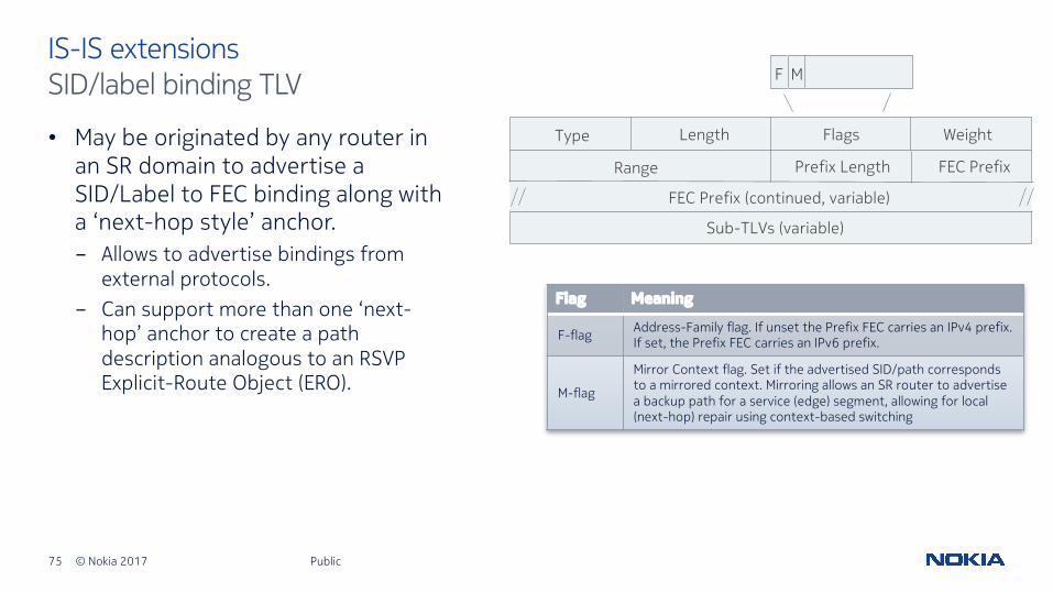
• May be originated by any router in an SR domain to advertise a SID/Label to FEC binding along with a ‘next-hop style’ anchor.- Allows to advertise bindings from
external protocols.- Can support more than one ‘next-
hop’ anchor to create a path description analogous to an RSVP Explicit-Route Object (ERO).
Public
IS-IS extensionsSID/label binding TLV
Flag Meaning
F-flag Address-Family flag. If unset the Prefix FEC carries an IPv4 prefix. If set, the Prefix FEC carries an IPv6 prefix.
M-flag
Mirror Context flag. Set if the advertised SID/path corresponds to a mirrored context. Mirroring allows an SR router to advertise a backup path for a service (edge) segment, allowing for local (next-hop) repair using context-based switching
Type Length Flags Weight
F M
Range Prefix Length FEC Prefix
FEC Prefix (continued, variable)
Sub-TLVs (variable)

76 © Nokia 2017
• Sub-TLVs field may contain:- SID/Label sub-TLV containing a
SID/MPLS label.- ERO Metric sub-TLV used to compare
the cost of a given source/destination path.
- IPv4 or IPv6 ERO sub-TLV and backup ERO sub-TLV, containing a list of strict or loose hops from source to destination for primary and backup paths.
- Unnumbered Interface ID ERO sub-TLV, containing interface index + router-Id to disambiguate from other unnumbered interfaces.
Public
IS-IS extensionsSID/label binding TLV (cont.)
Flag Meaning
Weight Represents the weight of the path for the purpose of load-balancing.
RangeProvides a compression scheme allowing a router to advertise a contiguous set of prefixes and their corresponding contiguous SID/label block.
Prefix Length
Contains the length of the prefix in bits.
FEC Prefix
The FEC at the tail-end of the advertised path. The FEC Prefix does not need to correspond to a routable prefix of the originating node.
Type Length Flags Weight
F M
Range Prefix Length FEC Prefix
FEC Prefix (continued, variable)
Sub-TLVs (variable)

77 © Nokia 2017
• Introduction of new Extended Prefix Opaque LSA defined to advertise additional prefix attributes.- Format of TLVs within the body of the LSA is
the same format as used by TE-Extensions to OSPF.
- Extended Prefix TLV used to advertise additional attributes associated with the prefix.
Public
OSPF extensionsExtended prefix opaque LSA
Field DescriptionRoute Type 0=unspecified, 1=intra-area, 2=inter-area, 5=external,
7=NSSA external
Prefix Length Length of the prefix
AF 0=IPv4 unicast
Address Prefix Prefix encoded as an even multiple of 32-bit words
LS Age
Opaque Type (7)
Advertising Router
LS Checksum
Instance
LS Sequence Number
Length
Options
TLVs (variable)
Type
Route Type Reserved
Address Prefix (variable)
Sub-TLVs (variable)
Length
Prefix Length AF
OSPF Extended Prefix TLV
OSPF Extended Prefix Opaque LSA

78 © Nokia 2017
• The Prefix SID Sub-TLV is a Sub-TLV of the OSPF Extended Prefix TLV.
• Support for Multi-Topology with MT-ID field.• Algorithm specifies algorithm the Prefix-SID
is associated with:• May also be carried in SR-Algorithm TLV of
Router Information Opaque LSA.
• Two values currently defined:- SPF (value 0)
- Strict SFP (value 1)
Public
OSPF extensionsPrefix-SID sub-TLV
Flag Meaning
NP-flag No-PHP flag. If set, the penultimate hop must not pop the Prefix-SID before delivering the packet to the advertising router.
M-flag Mapping Server Flag. If set, the SID is advertised from the Segment Routing Mapping Server.
E-flagExplicit-Null flag. If set, any upstream neighbour of the Prefix-SID originator must replace the Prefix-SID with a Prefix-SID having an Explicit-Null value before forwarding the packet.
V-flag Value flag. If set, the Prefix-SID carries an absolute value (instead of an index)
L-flag Local flag. If set, the value/index carried by the Prefix-SID has local significance.
Reserved
Type
ReservedRange Size
Length
MT-ID
SID/Index/Label (variable)
Flags Algorithm
MNP
E V L

79 © Nokia 2017
• Range allows for distribution of a contiguous prefix block and corresponding contiguous SID/label block. Range size >1 represents the number of addresses mapped into a Prefix-SID
• SID/Index/Label value contains either:– A 32-bit index defining the offset in the
SID/Label space advertised by this router
– A 24-bit label, where the 20 rightmost bits are used for encoding the label value
Public
OSPF extensionsPrefix-SID sub-TLV (cont.)
Flag Meaning
NP-flag No-PHP flag. If set, the penultimate hop must not pop the Prefix-SID before delivering the packet to the advertising router.
M-flag Mapping Server Flag. If set, the SID is advertised from the Segment Routing Mapping Server.
E-flagExplicit-Null flag. If set, any upstream neighbour of the Prefix-SID originator must replace the Prefix-SID with a Prefix-SID having an Explicit-Null value before forwarding the packet.
V-flag Value flag. If set, the Prefix-SID carries an absolute value (instead of an index)
L-flag Local flag. If set, the value/index carried by the Prefix-SID has local significance.
Reserved
Type
ReservedRange Size
Length
MT-ID
SID/Index/Label (variable)
Flags Algorithm
MNP
E V L

80 © Nokia 2017
• The SID/Label binding Sub-TLV is a Sub-TLV of the OSPF Extended Prefix LSA.
• It may be originated by any router in an SR domain to advertise a SID/Label to FEC binding along with at least one ‘next-hop style’ anchor.- Allows to advertise bindings from
external protocols
- Can support more than one ‘next-hop’ anchor to create a path description analogous to an RSVP ERO.
Public
OSPF extensionsSID/label binding sub-TLV
Flag Meaning
M-flag Mirror Context flag. Set if the advertised SID/path corresponds to a mirrored context.
ReservedReserved
Range Size
Length
MT-IDFlags Weight
M
Type
Sub-TLVs (variable)

81 © Nokia 2017
• Sub-TLVs field may contain:- SID/Label sub-TLV containing a
SID/MPLS label.
- ERO Metric sub-TLV used to compare the cost of a given source/destination path.
- IPv4 or IPv6 ERO sub-TLV and backup ERO sub-TLV, containing a list of strict or loose hops from source to destination for primary and backup paths.
- Unnumbered Interface ID ERO sub-TLV, containing interface index + router-Id to disambiguate from other unnumbered interfaces.
Public
OSPF extensionsSID/label binding sub-TLV (cont.)
Flag Meaning
MT-ID Support of Multi-Topology OSPF
Weight Represents the weight of the path for the purpose of load-balancing.
Range Size
Provides a compression scheme allowing a router to advertise a contiguous set of prefixes and their corresponding contiguous SID/label block. Value >1 represents the number of addresses mapped to the Prefix-SID
ReservedReserved
Range Size
Length
MT-IDFlags Weight
M
Type
Sub-TLVs (variable)

82 © Nokia 2017
• New Opaque LSA defined to advertise additional link attributes.
• Format of TLVs within the body of the LSA is the same format as used by TE-Extensions to OSPF.- Extended Link TLV used to advertise additional
attributes associated with the prefix (one for each Extended Link Opaque LSA).
Public
OSPF extensionsExtended link opaque LSA
Field Description
Link Type 1=Point-to-Point connection to another router, 2=Connection to a transit network, 3=Connection to a sub network, 4=Virtual link
Link ID 1=Point-to-Point connection to another router, 2=Connection to a transit network, 3=Connection to a sub network, 4=Virtual link
Link Data Value depends on link’s type field. See RFC 2328 Section A.4.2
LS Age
Opaque Type (8)
Advertising Router
LS Checksum
Instance
LS Sequence Number
Length
Options
TLVs (variable)
Type
Link Type Reserved
Link ID
Sub-TLVs (variable)
Length
OSPF Extended Link TLV
Link Data
OSPF Extended Link Opaque LSA
83 © Nokia 2017
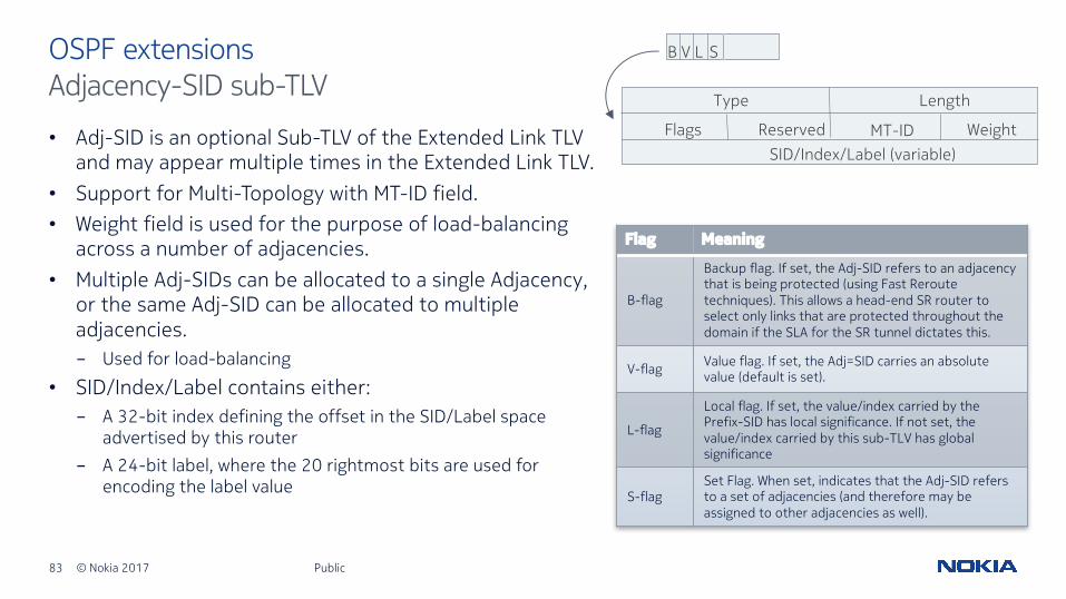
• Adj-SID is an optional Sub-TLV of the Extended Link TLV and may appear multiple times in the Extended Link TLV.
• Support for Multi-Topology with MT-ID field.• Weight field is used for the purpose of load-balancing
across a number of adjacencies.• Multiple Adj-SIDs can be allocated to a single Adjacency,
or the same Adj-SID can be allocated to multiple adjacencies.- Used for load-balancing
• SID/Index/Label contains either:- A 32-bit index defining the offset in the SID/Label space
advertised by this router - A 24-bit label, where the 20 rightmost bits are used for
encoding the label value
Public
OSPF extensionsAdjacency-SID sub-TLV
Flag Meaning
B-flag
Backup flag. If set, the Adj-SID refers to an adjacency that is being protected (using Fast Reroute techniques). This allows a head-end SR router to select only links that are protected throughout the domain if the SLA for the SR tunnel dictates this.
V-flag Value flag. If set, the Adj=SID carries an absolute value (default is set).
L-flag
Local flag. If set, the value/index carried by the Prefix-SID has local significance. If not set, the value/index carried by this sub-TLV has global significance
S-flagSet Flag. When set, indicates that the Adj-SID refers to a set of adjacencies (and therefore may be assigned to other adjacencies as well).
Type
Reserved
Length
MT-IDSID/Index/Label (variable)
Flags Weight
LB V S