

Page 1 of 39
ASSET COLLECTION & CONDITION
ASSESSMENT GUIDE
FOR
1’‐ <10’ SPAN CULVERTS
September, 2016
Revised:
XX.XX.XX

Page 2 of 39
CONTENTS
Introduction ................................................................................................................................................................ 4
General Collection Information .................................................................................................................................. 4
Approach ................................................................................................................................................................ 4
Limits ...................................................................................................................................................................... 5
Recommended Frequency of Collection ................................................................................................................ 5
Resource Requirements ............................................................................................................................................. 5
Personnel ................................................................................................................................................................ 5
Inspection Equipment ............................................................................................................................................ 6
Safety Precautions ...................................................................................................................................................... 6
General Safety Precautions .................................................................................................................................... 6
Additional Safety Considerations ........................................................................................................................... 6
Field Attribute Collection Procedure .......................................................................................................................... 6
Geospatially Locating Data in the Field ...................................................................................................................... 7
Collecting New Culvert Line and Culvert End Attributes ........................................................................................ 7
Editing an Existing Culvert Line and Culvert End Attributes ................................................................................. 10
Office ........................................................................................................................................................................ 12
QA/QC Using ArcGIS Online .................................................................................................................................. 12
Data Collection Requirements .................................................................................................................................. 13
Data Organization ................................................................................................................................................. 13
Attribute Collection Guidance .............................................................................................................................. 16
Location Information Requirements & Guidance ................................................................................................. 23
Elevation ........................................................................................................................................................... 23
Collection Method ............................................................................................................................................ 23
Spatial Quality Index ......................................................................................................................................... 23
Culvert Condition Assessment Guidance.................................................................................................................. 24
Condition Assessment ‐ Field Attribute Collection Procedure ............................................................................. 24
Culvert Condition Ratings ..................................................................................................................................... 24
Attribute Fields ..................................................................................................................................................... 27
Condition Description & Examples ....................................................................................................................... 29
Definitions ................................................................................................................................................................ 36
For More Information ............................................................................................................................................... 37
Faqs .......................................................................................................................................................................... 37
Appendicies .............................................................................................................................................................. 38

Page 3 of 39
Appendix A: Spatial Quality Index – Options ........................................................................................................ 38
Appendix B: MDOT County Code List ................................................................................................................... 39

Page 4 of 39
INTRODUCTION
In 2015 the Michigan Department of Transportation (MDOT) initiated TAMS (Transportation Asset Management
System). MDOT’s TAMS takes a GIS centric approach to asset management requiring spatial data collection by
asset type. The asset information is used to drive maintenance management and decision making.
Prior to the initiation of TAMS, only culverts with a span of 10 and larger were inventoried and regularly
inspected. These culverts are inventoried as part of the NBIS (National Bridge Information System) and have
inspections set up according to NBIS standards.
The TAMS process inventories and establishes a monitoring protocol for smaller culverts than those inventoried
in the NBIS. Culverts with spans between 1’ and less than 10’ will fall under the guidelines of the TAMS process
for inspection, rating, and asset inventory. This manual provides the various asset attributes to be collected for
culverts, proper coding of the various attributes, and how to rate a culverts condition at the time of installation
or inspection. This information will then be used to plan maintenance activities at individual culverts and along
road corridors.
Attribute collection guidance is provided in this manual. The guidance covers how specific asset attributes are to
be recorded for type, size, and location of culvert assets. A second guide in this manual will assist with
developing an overall condition rating for the asset. The coding guide was taken from FHWA’s Culvert Inspection
Manual and is intended to provide a systematic review of the asset attributes so that a consistent approach to
culvert condition rating will be applied statewide.
GENERAL COLLECTION INFORMATION
APPROACH
To initially populate the TAMS system, asset and attribute collection will normally be done in a two‐stage
process. The first stage requires the location of the asset (culvert) geospatially using approved data collector.
Each region will train at least one Region collection crew to register the location information of the culverts in
their area of responsibility. Data collected by the initial survey crew will include geo‐locating each end of the
culvert and include type, size, location, and site attributes.
The second stage of the process involves a crew (can be 1 person) to collect the required condition attribute
information of the culvert. These attributes include information on deterioration, deformation, joint stability,
scour protection, and other attributes. These attributes will be collected using the Vueworks software following
methods promoted by the TAMS collection methods team. The crew must be trained in the use, operation, and
data collection requirements prior to any field data collection. Once the condition attributes have been
collected, Vueworks will calculate an overall condition rating for the asset.
Culverts that are replaced or modified as part of a construction project will have the geo‐location and condition
attribute information collected by the same crews once final acceptance of the project occurs.
In the event that a culvert is discovered that is not included in the TAMS system, the region collection crew
should be contacted to collect the geospatial and attribute information into the system. Once the culvert type,
size, and location information has been collected, it should be scheduled for a condition assessment.

Page 5 of 39
LIMITS
Culvert assets that convey water through or along the MDOT ROW with a span between 1’ and less than 10’ will
be collected as part of the TAMS process. Culverts 10’ and larger are collected and inspected based on FHWA
NBIS criteria and are not part of this effort. Storm sewer outfalls are not collected under the culvert asset
collection criteria.
Culverts with spans outside of the recommendations above can still be collected and included in each regions
data collection process. If a particular region chooses to collect data on culverts outside of the TAMS
requirements (or collect data on any other feature not included in the initial TAMS asset collection), data
collection and attribute information should follow the guidelines listed in this document. It should be noted that
culverts 10’ and larger will fall under the inspection requirements of the NBI system and not the schedule
recommended in this document
It should be noted that ratings generated for culverts are based on specific TAMS asset attributes. There are
other attributes that are not part of the TAMS data collection that could lead to further work at a given location.
Inspection crews that identify potential issues that are not covered by TAMS data collection should notify the
Region Engineer. The Region Engineer should then determine what work needs to be done, choose an
appropriate schedule for the work, and notify any specialty areas (i.e. Hydraulics, Geotechnical, etc.) of the
upcoming work.
During the condition assessment data collection, sites may be identified where the fix would be considered more
than just maintenance. These cases should be directed to the Region Engineer so that a project can be
programmed for the required work.
RECOMMENDED FREQUENCY OF COLLECTION
It is recommended that asset data be collected after initial construction or during any reconstruction or
maintenance to the asset. Culverts that meet the TAMS data collection criteria will be inspected according to the
following recommendations as a result of the inspection.
Condition rating 8 ‐ 9, continue with a 5 year inspection cycle.
Condition rating 6‐7, inspect on a 2 year cycle if not in current year maintenance program.
Condition rating 5, inspect on annual cycle if not in current year maintenance program.
Condition rating 1 through 4, road closure imminent, repairs must be scheduled.
RESOURCE REQUIREMENTS
PERSONNEL
A properly outfitted crew of 1 or 2 people, depending on experience, is needed to perform field data collection.
Staff should be familiar with this document before attempting to collect asset attribute information. Each region
can determine who will be doing data collection, however, students are discouraged from being the primary field
collection resource and Civil Service rules prohibit the use of Co‐Ops for data collection

Page 6 of 39
INSPECTION EQUIPMENT
The following equipment is required:
Measuring tools, hand tools
Approved data collection device
Flashlight
Safety equipment, including PPE
Properly sized waders
Stability pole
SAFETY PRECAUTIONS
GENERAL SAFETY PRECAUTIONS
Ensure safe practices are utilized while performing all inventory collection and condition assessment
field activities. All work must comply with MDOT, OSHA and MiOSHA procedures and regulations.
Ensure that proper personal protective equipment (PPE) is used in accordance with MDOT’s Personal
Protective Equipment Policy – Guidance Document 10118.
http://mdotcfintra.state.mi.us/interchange/guidocs/files/10118.pdf
Ensure that safe practices are followed according to Michigan Manual of Uniform Traffic Control Devices
http://mdotcf.state.mi.us/public/tands/plans.cfm and the Work Zone Safety and Mobility Manual
http://www.michigan.gov/documents/mdot/MDOT_WorkZoneSafetyAndMobilityManual_233891_7.pd
f
ADDITIONAL SAFETY CONSIDERATIONS
Culverts can be considered confined spaces and should not be entered unless the individual or individuals
collecting the asset data on the culvert have completed confined space entry training.
Asset collection and rating should not be performed during times of high flows. High flows can easily sweep an
individual off of their feet or contain debris, both seen and unseen, that can create a very dangerous situation for
anyone collecting asset information.
Asset collection requires information to be collected at each end of a culvert. The crew performing this task may
have to deal with live traffic situations with no traffic control. Great care must be exercised every time the crew
exposes themselves to live traffic.
FIELD ATTRIBUTE COLLECTION PROCEDURE
Field collection must be done in an orderly process. Staff collecting attributes should collect all pertinent data at
one end of the culvert before proceeding to the opposite end of the culvert or a different culvert along the route.
Collecting attribute data requires close inspection of the exterior of the culvert, road embankment and road
itself. Staff collecting data should also look into the culvert to see if there are any issues with separation,
sedimentation, and material and/or shape changes.
Attribute data should be collected at installation, during routine inspections, and after any maintenance has
been completed.

Page 7 of 39
GEOSPATIALLY LOCATING DATA IN THE FIELD
COLLECTING NEW CULVERT LINE AND CULVERT END ATTRIBUTES
*Images and steps listed below are in reference to Collector for ArcGIS using a Leica Zeno 20 running Android
mobile operating system. The use of “streaming” is not permitted for geospatial location of culvert lines‐ the field
crew must shoot an individual point at each culvert end.
Select your PR based on your location and the road your culvert is located on. It will become a cyan color when
selected.
Click on the white box at the bottom of your screen then select new
Page 8 of 39
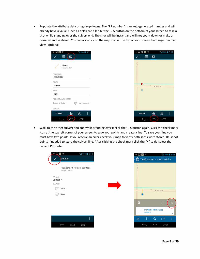
Populate the attribute data using drop downs. The “PR number” is an auto generated number and will
already have a value. Once all fields are filled hit the GPS button on the bottom of your screen to take a
shot while standing over the culvert end. The shot will be instant and will not count down or make a
noise when it is stored. You can also click on the map icon at the top of your screen to change to a map
view (optional).
Walk to the other culvert end and while standing over it click the GPS button again. Click the check mark
icon at the top left corner of your screen to save your points and create a line. To save your line you
must have two points. If you receive an error check your map to verify both shots were stored. Re‐shoot
points if needed to store the culvert line. After clicking the check mark click the “X” to de‐select the
current PR route.

Page 9 of 39
To record attribute information for each culvert end select the culvert line you created in the previous
steps. Click on the white box at the bottom of your screen then scroll to the bottom of the page and
select new for culvert ends
Populate attribute data for each end. To save the data when finished click the check mark in the top left
corner of the screen

Page 10 of 39
EDITING AN EXISTING CULVERT LINE AND CULVERT END ATTRIBUTES
Some instances with heavy traffic do not allow the field crew to safely collect each end of the culvert at the same
time. In these situations it is recommended to collect one end of the culvert then walk approximately on line
with the culvert to the edge of shoulder and take a GPS shot here to create a temporary line. A line cannot be left
“open” in Collector for ArcGIS so a temporary line is used and edited later to correct its end point. After creating
your temporary line create a new culvert end and populate its attributes for the correct end you are at. The steps
listed below are to edit an existing temporary line.
Select the line you want to edit then click on the white box at the bottom of the screen
Click on the edit button in the lower left corner of the screen then switch to the map view by clicking the
map icon at the top of your screen.

Page 11 of 39
Standing over the remaining needed culvert end click the GPS button to extend the existing temporary
culvert line. Although you do not need to be in the map view to perform this operation, it helps to
visually see the line is drawn.
With the extended line still active for editing click on vertex needing to be removed which will allow for
a straight line then click the 3 vertical dots in the bottom right corner of the screen and select delete
vertex

Page 12 of 39
You will still need to add the new culvert end and populate the attribute data. Click the check box in the
top left corner of your screen to save your changes
OFFICE
QA/QC USING ARCGIS ONLINE
To ensure proper QA/QC, utilize ArcGIS Online (AGO) to review the geospatially located features. Although it is
not expected to review each culvert collected in the office spot, checking and scanning will prevent mistakes and
return visits for missing information. All actions available to the user in the office on AGO are also available to the
user in the field inside the Collector for ArcGIS application. Items to pay attention to in AGO include but are not
limited to:
Line completeness
Were any edits missed in the field for deleting vertices?
Is there missing attribute information for culvert lines or culvert ends?
Office procedures to upload and review data, along with quality control and quality assurance should follow best
practices as outlined by collection methods team.

Page 13 of 39
DATA COLLECTION REQUIREMENTS
DATA ORGANIZATION
Data organization for all MDOT asset data will adhere to the following high level organization and order
(Location, Asset, and Condition – LAC): Location and Asset information for culverts will be collected using
prescribed data collection tools. Condition of the culvert will be collected using the Vueworks software.
Unique Identifier Location
Asset
Condition
Culvert data will be split into two primary layers: Barrel Attributes and End Attributes. Barrel attributes will be a
line layer and will be the primary layer. Barrel End Attributes will be stored in a table as records and are linked to
the Barrel Line feature.
The unique identifiers for the Barrel Line and Barrel Ends will be an auto‐generated GUID’s created at the time of
collection by the GIS tools.
Unique ID’s for the Barrel Group ID field will not be auto‐generated and must be inputted by the data collector
where applicable. The methodology for creating this ID is described below.
Barrel Attributes General Field Field
DescriptionFormat Field
Options Notes
Unique ID
GlobalID This ID will be created for each barrel
GUID (Auto gen)
GUID Alias will be Barrel ID
CulvertGroupId Smart-Key 2 digit county (Appendix B) 3 digit route 2 digit sequential.
Concatenated Smart-Key
Example: 3rd culvert group location in Ingham county on I-96 would be 3309603.
Location
Route M (state route), I (interstate), US (United States), SL (state lands), RA (rest area) or FL (federal lands).
Pick from list
This list will have all I, M and US routes
Beneath Pick from List
Mainline, Ramp, Service Drive, Driveway

Page 14 of 39
Barrel Attributes (Continued)
General Field Field Description
Format Field Options
Notes
Asset
CulvertInstallationDate Date If installation date is unknown, enter 1900.
AssetCollectionDate Automatically populated
through GIS
Date
CulvertMaterial Pick from list
Metal, Concrete, Plastic
CulvertShape Pick from list
Circular, Horizontal Elliptical, Vertical Elliptical, Arch, 3-sided (footings), 4-sided
CulvertHeight (in) Numeric
CulvertWidth (in) Numeric
Liner Y/N
DepthOfCover Amount of fill above top of
barrel.
Y/N
LinerMaterial Pick from list
Plastic (smooth), Plastic (Corrugated), CIPP
LinerDiameter (in) Numeric
SpatialQualityIndex Pick from List
A, B, C, D, E. See Appendix A for index definitions
Condition
OverallCondition Condition Rating 9-1
Calculated and pushed from Vueworks

Page 15 of 39
End Attributes Field Field
DescriptionFormat Field Options Notes
Unique ID
CulvertId This will auto populate from
the related Feature Class
GUID GUID Field Related to Barrel GlobalID
GlobalID Each barrel will have two ends
to record information.
GUID GUID Alias EndID
Asset
EndSection Pick from List
None Headwall HW w wing Beveled Sloped Flared Mitered
EndSectionMaterial Pick from List
Metal Concrete Clay Plastic
InvertAboveChannel Bottom Y/N
Riprap Y/N
SafetyGrate Y/N Default No
EndExtension Y/N Default No
ExtensionMaterialSameAs OriginalCulvert
Y/N Yes, No, NA
ExtensionShapeSameAs OriginalCulvert
Y/N Yes, No, NA
ExtensionDimensionsSame AsOriginalCulvert
Y/N Yes, No, NA

Page 16 of 39
ATTRIBUTE COLLECTION GUIDANCE
Each Culvert Barrel, Box, or Pipe should be collected as a single culvert with corresponding culvert ends.
Data is to be collected at each end of a culvert. Cardinal directions shall be used to define how to choose culvert
end 1 and culvert end 2. Culvert end 1 shall be the end on the south or west side of the road. End 2 shall be on
the north or east side of the road. At locations that do not follow true cardinal directions, the signed direction of
the road shall be the basis of determining north, south, east, and west.
GlobalId ‐ A unique auto‐generated GUID for each barrel.
CulvertGroupId – Enter the site identification of a culvert group location (for multiple culvert locations
only). See appendix B for county code index to use along with route id and group number. Culverts that
are separated by less than 10’ of earthen fill, even if they share a common headwall, would be
considered multiple culverts. ‐ Pay close attention that a twin opening culvert could be considered a
single culvert with 2 barrels. If a structural member splits the culvert, then it would be considered a
single culvert with multiple barrels.
Example of a single culvert with 2 barrels (collect each barrel separately)
Examples of multiple culverts
Route ‐ Pick route name from field list.
Beneath – Pick what the culvert is beneath from the pick list.

Page 17 of 39
CulvertInstallationDate – Year culvert was installed. Culvert installation dates should be entered into the
system upon acceptance of work by the project manager. During initial data collection, installation
dates should be taken from design plans. If no plans are available or if the culvert in the field does not
match what’s detailed on the plans, an installation year of 1900 shall be used.
AssetCollectionDate – Actual date of collection (MM, DD, YYYY)
CulvertMaterial – Culvert material selections include metal, concrete, plastic, and clay (rarely)
Example of metal culvert Example of concrete culvert
Example of plastic culverts

Page 18 of 39
CulvertShape – Culverts can come in a variety of shapes including circular, horizontal elliptical, vertical
elliptical, arch, 3‐sided (footings), 4‐sided. The culvert shape attribute should describe the main culvert
under the road and not an extension (if any).
Circular culvert Horizontal ellipse (vertical ellipse would have axis
rotated 90 degrees)
Arch culvert Box culvert (has poured bottom)
3‐sided (no floor in culvert)

Page 19 of 39
CulvertHeight – The vertical measurement (top of the pipe to the bottom of the pipe or natural bottom
if in a 3‐sided culvert) in inches. Measurement should reflect the interior dimension of the culvert.
Height and width are the same for circular culverts.
CulvertWidth – The horizontal measurement of the culvert in inches. Measurement should reflect the
interior dimension of the culvert. Height and width are the same for circular culverts.
Liner – Has culvert been lined in the past? If so, choose “yes”. Typically, pipes are lined using a smaller
plastic pipe inserted into a larger pipe or a cured in place liner is used.
LinerMaterial – If Culvert Liner attribute is “yes”, choose liner material. Materials are typically plastic or
a cured in place liner. Plastic liners inserted in a pipe should be listed as smooth or corrugated based on
their interior.
Concrete culvert with plastic liner Cured in place (CIPP) liner
LinerDiameter –Measurement should reflect the interior dimension of the culvert. Height and width are
the same for circular culverts.
DepthOfCover – This attribute relates to the amount of fill over a culvert. If distance from the road
surface to the top of culvert is 5’ or more, choose “Yes” for this attribute.
Depth of cover <5’
End ID (Alias) – GlobalID GUID linked to barrel

Page 20 of 39
EndSection – None, Headwall, Headwall w/ wingwalls, Beveled, sloped, flared, or mitered
None Headwall
Headwall with wingwalls
Beveled (Concrete only) – hand formed 45 Flared end section
degree angle between culvert and headwall

Page 21 of 39
Mitered end
EndSectionMaterial ‐ List end section material. Choices include Metal, Concrete, Clay, Plastic, None
Metal end section Concrete end section
Plastic end section No end section
InvertAboveChannelBottom – is invert of end above the channel bottom, yes or no

Page 22 of 39
SafetyGrate – Is there a safety grate on either end of the culvert. If so, choose “yes”.
Examples of safety grates on culverts
EndExtended – Has the original culvert been extended, yes or no
Example of culvert that has been extended multiple times (note different material and shape of current
outlet when compared to the existing culvert).
ExtensionMaterialSameAsOriginalCulvert – If culvert has been extended, does the extension material
match the original culvert material?
ExtensionDimensionsSameAsOriginalCulvert – If the culvert has been extended, do the interior
dimensions of the extension match those of the original culvert?
ExtensionShapeSameAsOriginalCulvert – See “End 1 Extension shape same as original culvert” attribute
above.
SpatialQualityIndex – A, B, C, D, E. Refer to Appendix A for values.

Page 23 of 39
LOCATION INFORMATION REQUIREMENTS & GUIDANCE
The default linear referencing for business viewing is control section milepoint. It is understood that TAMS will
also reference PR and route milepoints, and users should have the ability to view those milepoints as well.
ELEVATION
Elevation Data is not required for business purposes and is not part of the field collection process. When
defined by business area, the elevation value of the asset, expressed in units of international feet to the decimal
value appropriate to the capable precision of the collection method utilized. The values are relative to the North
American Vertical Datum of 1988 (NAVD 88).
Format: XXX.XX Example: 743.14
COLLECTION METHOD
Collection methods shall be at the direction of the TAMS collection methods team, in order to collect required
information. This manual serves as a guide for noting the attributes to be collected but it will be up to each
collection team to determine the most effective way of collecting asset attributes.
SPATIAL QUALITY INDEX
Mapping grade (Level C) is sufficient for culvert business purposes. This entails sub‐meter accuracy levels for XY
elements, typically achieved with corrected mapping graded (handheld) GPS collection procedures. Levels A and
B are also acceptable.

Page 24 of 39
CULVERT CONDITION ASSESSMENT GUIDANCE
The following scale will be used to rate the overall operational status of a culvert as well as indicate actions
needed for repair. The overall asset rating will be generated by the Vueworks software and is based on the
individual condition attribute ratings. The rating will be stored both in Vueworks and in the GIS spatial data
tables.
Culvert Condition Rating
9 – No repairs needed
8 – No repairs needed, list specific items for special inspection during next regular inspection
7 – No immediate plan for repair; examine possibility of increased level of inspection
6 – By end of next season; add to work schedule
5 – Place in current schedule/current season/first reasonable opportunity
4 – Priority, current season; review work plan for relative priority, adjust schedule if possible
3 – High priority; current season as soon as can be scheduled
2 – Highest Priority; discontinue other work if required, emergency basis
1 – Emergency action required; re‐route traffic and close
CONDITION ASSESSMENT ‐ FIELD ATTRIBUTE COLLECTION PROCEDURE
Field collection must be done in an orderly process. Staff collecting attributes should collect all pertinent data at
one end of the culvert before proceeding to the opposite end of the culvert or a different culvert along the route.
Collecting condition attribute data requires close inspection of the interior and exterior of the culvert, road
embankment and road itself.
CULVERT CONDITION RATINGS
Vueworks will create an overall condition rating for each culvert based on the appropriate condition attributes in
Table 1. Some attributes are specific to a particular culvert material or installation and may not be included in
the overall rating calculation.
Any condition assessment that has a value of 3 or less will automatically cause the overall condition rating to
default to that minimum rating.

Page 25 of 39
Table 1: Condition Attributes and Rating Scale
Attribute
Good
9‐8
Fair
7‐6
Poor
5‐4
Critical
3‐1
Invert Deterioration (Metal)
Little or no surface rust or coating loss
General corrosion, scaling, or pitting but significant remaining metal section.
Perforations visible or easily made by hammer test strike.
Significant section loss in invert beyond perforations resulting in voids beneath invert and/or roadway/embankment damage.
Invert Deterioration (Concrete)
Little or no abrasion with aggregate exposed.
Moderate abrasion and scaling with minor aggregate loss. No exposure of reinforcement.
Heavy abrasion and scaling with exposed reinforcement.
Holes or section loss with voids beneath and roadway/embankment damage.
Joints No gaps Open with minor infil/exfil of water and/or soil
Open or displaced with significant infil/exfil of soil and water. Voids visible
Open or displaced with significant infiltration of soil with accompanying roadway damage.
Section Deformation
None Slight, perceptible deformation or local bulging
Deformation with longitudinal cracking or crushing in crown, invert, or spring lines.
Excessive deformation resulting in extensive infiltration of soil with roadway/embankment damage.
Corrosion (Metal)
Little or no surface rust or coating loss
Minor surface rust and limited pitting
Perforations visible or easily made, connection hardware failing
Significant section loss resulting in extensive infiltration of soil with roadway/embankment damage.
Corrosion (Concrete)
Little to no efflorescence
Minor cracking and spalling.
Exposed reinforcement
Significant section loss of steel reinforcement that causes pipe deformation, holes, and embankment/roadway damage.
Road over Same condition as initial placement
Minor cracking along culvert all or part of culvert length.
Multiple patches applied to area over culvert.
Significant damage to road surface where failure is imminent or has occurred.

Page 26 of 39
Table 1: Condition Attributes and Rating Scale (Continued)
Attribute Good
9‐8
Fair
7‐6
Poor
5‐4
Critical
3‐1
End Section No undermining Minor undermining
Broken, Crushed or separated from barrel.
Deterioration is affecting performance or causing roadway/embankment damage.
Apron No cracking or undermining.
Minor cracking but no undermining.
Significant cracking over >50% of apron or significant undermining.
Partially or totally collapsed causing roadway/embankment damage.
Scour Present Stream width consistent with culvert inlet/outlet.
Stream has minor widening at culvert inlet/outlet
Stream significantly wider at culvert inlet/outlet. Minor local erosion of streambanks.
Stream significantly wider at culvert inlet/outlet. Stream banks showing significant erosion.
Scour Protection *
Same condition as initial placement
Some material has moved off site but no damage to structure or embankment.
Material section loss is evident. Minor damage to structure or embankment.
Material has deteriorated or moved off site. Significant damage to road embankment or structure.
Sediment ** Same condition as initial placement
Additional material has moved into culvert but does not exceed 20% of rise.
Sediment exceeds 20% but is less than 50% of rise.
Sediment significantly impacting the capacity of the culvert.
Invert Location
Same location as initial placement.
Culvert inlet/outlet is above channel invert by less than 4".
Culvert inlet/outlet is above the channel invert by 6" with water dropping into pool below. Blocks some organism passage.
Culvert significantly above channel invert with water freefalling into pool below. Blocks most organism passage and significant damage to road or embankment occurring.

Page 27 of 39
Table 1: Condition Attributes and Rating Scale (Continued)
Attribute Good
9‐8
Fair
7‐6
Poor
5‐4
Critical
3‐1
Embankment Same as initial construction
Minor depressions in embankment but not under road.
Notable depressions in or active erosion of the embankment. Road is being threatened.
Failure of embankment has occurred or is imminent.
Footing Exposed?
Footing not visible.
Footing exposed. Undermining possible.
* This rating is specific to riprap. If other scour protection material is used, new criteria need to be developed.
** Some culverts are intentionally recessed. Check plans to verify culvert invert and stream flowlines.
ATTRIBUTE FIELDS
The following condition attributes determine the overall condition rating for the asset. Not all attributes apply to
every culvert. Most attributes have a selection criteria based on a scale from 9‐1 with 9 being good condition to
1 being at or near failure. However, the “Footing Exposed” attribute is limited in its condition ratings and
essentially act as pass/fail rating.
If there are any questions on how to rate a particular structure condition attribute, contact the Hydraulics Unit
for further assistance.

Page 28 of 39
Culvert Condition Assessment Attributes (Vueworks)
Field Field Description
Format Field Options Notes
(Metal) Invert Deterioration Condition Rating 9-1
Selection 9-1
(Conc) Invert Deterioration Condition Rating 9-1
Selection 9-1
Joints Condition Rating 9-1
Selection 9-1
Section Deformation Condition Rating 9-1
Selection 9-1
(Metal) Corrosion Condition Rating 9-1
Selection 9-1
(Conc) Corrosion Condition Rating 9-1
Selection 9-1
Road Condition Above Condition Rating 9-1
Selection 9-1
End Section 1 Condition Rating 9-1
Selection 9-1
End Section 2 Condition Rating 9-1
Selection 9-1
Apron 1 Condition Rating 9-1
Selection 9-1
Apron 2 Condition Rating 9-1
Selection 9-1
Scour Condition Rating 9-1
Selection 9-1
Scour Protection Condition Rating 9-1
Selection 9-1
Sediment Condition Rating 9-1
Selection 9-1
Invert Location Condition Rating 9-1
Selection 9-1
Embankment Condition Rating 9-1
Selection 9-1
FootingExposed Condition Rating 9 or 3
Selection 9 or 3 only for 3-sided culverts

Page 29 of 39
CONDITION DESCRIPTION & EXAMPLES
The following pictures illustrate how to code many of the condition attributes. More will be added as pictures
become available.
Invert Deterioration (Metal) – Examples
Condition rating 7 or less Condition rating 2 or less
Invert Deterioration (Concrete) – Images pending.
Joints – Condition of joints throughout culvert.
Joint separation in culvert‐ condition rating of 3

Page 30 of 39
Section Deformation ‐ Examples
Condition rating 6 or less Slab culvert with failed wall
Condition rating 3 or less
Corrosion (Metal) ‐ Examples
Significant rust with section loss
Condition rating 3 or less
Corrosion (Concrete) – Images pending

Page 31 of 39
Road Over ‐ Condition of surface directly above culvert asset.
Condition rating: 9 Condition rating: 6 or 7
Condition rating: 1
End Section (1 or 2) – Is the end section detached from the culvert? A Yes” value defaults the condition
rating to 3.
Detached end section‐ condition rating of 3.
Apron (1 or 2) –Images pending

Page 32 of 39
Scour – Scour results in perched culverts (culvert invert above the channel bottom) and plunge pools
downstream of the culvert. Both are caused by erosive velocities. If scour is present at either end of
the culvert, choose condition rating for worst side.
Plunge pool at culvert outlet. Note the channel width immediately downstream of the culvert compared
to the actual stream width – condition rating of 5 or less

Page 33 of 39
Scour Protection ‐ Use condition rating guide and rate 1‐9. Example ratings are as follows:
Riprap condition rating of 9. Riprap condition rating of 5 or less (poor material,
Riprap in same condition as initial placement non‐interlocking, only 1 layer remaining).
Riprap condition rating of 3 or less
(Material has failed, significant loss of embankment).
Sediment ‐ % Blockage is based on total height of culvert and depth of sediment (excluding any designed
recess).
Sediment blocking more than 50% of culvert depth –condition rating of 3 or less
Page 34 of 39
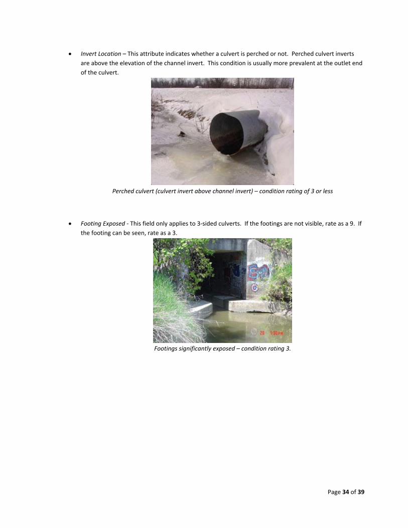
Invert Location – This attribute indicates whether a culvert is perched or not. Perched culvert inverts
are above the elevation of the channel invert. This condition is usually more prevalent at the outlet end
of the culvert.
Perched culvert (culvert invert above channel invert) – condition rating of 3 or less
Footing Exposed ‐ This field only applies to 3‐sided culverts. If the footings are not visible, rate as a 9. If
the footing can be seen, rate as a 3.
Footings significantly exposed – condition rating 3.

Page 35 of 39
Embankment Condition – Examine condition of embankment from top of culvert(s) to the road surface.
Embankment in same condition as design ‐ Depressions forming above twin culverts ‐
condition rating of 8 or higher. condition rating of 6 or less.
Embankment has failed is affecting traffic ‐
condition rating of 2 or less.

Page 36 of 39
DEFINITIONS
Cover – The amount of earthen fill above the culvert. Measured from top of road surface to top of culvert.
Culvert Extensions – adding additional length to a previously placed culvert. Extensions may or may not be the
same material or shape as the originally constructed culvert.
Invert – The lowest interior point of a culvert, excluding any sediment.
Flow Line – The lowest point at which water flows through a culvert. It can be located at the culvert invert (if not
recessed) or at the top of the sediment elevation.
Perch – When the culvert invert is above the natural channel bottom elevation.
Recess – The amount of depth the culvert invert is below the natural channel.
Sediment – Soil that has naturally accumulated within a culvert. Some culverts on natural streams are designed
to retain a small amount of sediment to provide a natural channel bottom for aquatic organisms.
Streaming – A method of collecting points at a pre‐determined time interval or distance between observations.
Wingwall / End Section / Headwall ‐ The structures at the inlet and/or outlet of a culvert. Usually placed to
retain road embankment and provide hydraulic efficiency to a culvert.

Page 37 of 39
FOR MORE INFORMATION
ASSET BUSINESS OWNER: Taylor Snow Hydraulics Engineer [email protected]
DATA MANAGEMENT: GIS Team 517‐285‐6762
DOCUMENT STEWARD: Taylor Snow Hydraulics Engineer [email protected]
ASSET GUIDE DEVELOPMENT TEAM:
Chris Potvin, Hydraulics Nicholas Ryan, Design Surveys Kevin McKnight, Planning Cory Johnson, Planning Melissa Howe, OFS Darrell Heuker, Grand Rapids TSC Rob Hall, Gaylord TSC Rick Weaver, Southwest Region Fennville Garage Therese Kline, Bridge Justin Droste, OFS TAMS Engineer
FAQS

Page 38 of 39
APPENDICIES
APPENDIX A: SPATIAL QUALITY INDEX – OPTIONS
Index Equivalent Definition
A Survey Grade – 3D Sub centimeter accuracy levels for XYZ elements, typically achieved by utilizing field Survey grade collection procedures or “1A” LiDAR. Also applies to assets harvested from CAD engineering drawings. Data acceptable for engineering uses provided it is validated before use.
B Survey Grade – 2D Sub‐centimeter accuracy levels for XY elements, typically achieved by utilizing field GPS – Survey Grade collection procedures or “2B” trajectory processed LiDAR without control.
C Mapping Grade Sub‐meter accuracy levels for XY elements, typically achieved with corrected mapping graded (handheld) GPS collection procedures (generally acceptable for maintenance operations).
D Informational Decimeter accuracy levels typically achieved by digitizing from orthophotos or other rectified imagery.
E Unknown

Page 39 of 39
APPENDIX B: MDOT COUNTY CODE LIST
MDOT County Code List
(8-16-2016)
COUNTY NO. COUNTY NO. COUNTY NO.
Alcona 01 Gratiot 29 Missaukee 57
Alger 02 Hillsdale 30 Monroe 58
Allegan 03 Houghton 31 Montcalm 59
Alpena 04 Huron 32 Montmorency 60
Antrim 05 Ingham 33 Muskegon 61
Arenac 06 Ionia 34 Newaygo 62
Baraga 07 Iosco 35 Oakland 63
Barry 08 Iron 36 Oceana 64
Bay 09 Isabella 37 Ogemaw 65
Benzie 10 Jackson 38 Ontonagon 66
Berrien 11 Kalamazoo 39 Osceola 67
Branch 12 Kalkaska 40 Oscoda 68
Calhoun 13 Kent 41 Otsego 69
Cass 14 Keweenaw 42 Ottawa 70
Charlevoix 15 Lake 43 Presque Isle 71
Cheboygan 16 Lapeer 44 Roscommon 72
Chippewa 17 Leelanau 45 Saginaw 73
Clare 18 Lenawee 46 Sanilac 74
Clinton 19 Livingston 47 Schoolcraft 75
Crawford 20 Luce 48 Shiawassee 76
Delta 21 Mackinac 49 St. Clair 77
Dickinson 22 Macomb 50 St. Joseph 78
Eaton 23 Manistee 51 Tuscola 79
Emmet 24 Marquette 52 Van Buren 80
Genesee 25 Mason 53 Washtenaw 81
Gladwin 26 Mecosta 54 Wayne 82
Gogebic 27 Menominee 55 Wexford 83
Grand Traverse 28 Midland 56


