

Atlas Copco Ground Engineering Products
Overburden drilling catalogue
Odex™ Overburden drilling systems

2
As much as 90% of the land surface of the earth is coveredwith loose, unconsolidated material such as soil, clay, silt,sand, gravel and boulders, which varies in depth from a fewcentimetres to hundreds of meters.
Drilling through this so-called overburden is often problematic,due to the tendency of the earth to cave in behind the drill bit.This makes it difficult to retrieve the drill string after the holehas been drilled. In practice, the bore hole is often lost before a casing tube can be inserted to support it.
Other problems are caused by cavities or porous ground, whichinterfere with the circulation of the flushing medium andprevent the drill cuttings from being flushed out of the hole.
In places where overburden strata are mixed, or when theirdrillability is unknown, it is difficult for the driller to decidewhat tools to use in order to get the best overall resultswithout risking the loss of equipment in the hole.
The best solution for dealing with such problems is to useODEX equipment.
Overburden
drilling
CONTENTSThe ODEX method ........................................ 3ODEX drilling step-by-step........................... 4Rock drill recommendations ....................... 4The ODEX product range, data ................... 5ODEX 90T-G2.............................................. 6-7ODEX 115T-G2 ........................................... 8-9ODEX 140T-G2 .........................................10-11ODEX 165T-G2 .........................................12-13ODEX 90W-G2 .........................................14-15ODEX 115W-G2........................................16-17ODEX 140W-G2........................................18-19ODEX 165W-G2 ...................................... 20-21ODEX 190W-G2 ...................................... 22-23ODEX 240W-G2 ...................................... 24-25ODEX 76T, ODEX 76W ........................... 26-27ODEX 90/115 ........................................... 28-29Auxiliary tools ........................................ 30-31Ball locking system ODEX G2 ................... 33Dimensions ........................................... 34-35Recommendations, DTH Hammers........... 36Conversion factors ..................................... 38Weights and cross index ........................... 39
Designs and product range are subject to alterationwithout prior notice.

3
ODEX equipment enables you to drill and case deep holessimultaneously in all types of formation, even those with large boulders. Casing diameters from 89 mm (ODEX 76) to 273 mm (ODEX 240) can be used.
The method is based on a pilot bit and eccentric reamer,which together drill a hole slightly larger than the externaldiameter of the casing tube. This enables the casing tube to follow the drill bit down the hole.
When using ODEX, part of the impact energy is diverted to thecasing tube via a shoulder on the guide device, which in turnimpacts a special casing shoe at the lower end of the casing.
ODEX 76 for top hammers operates with impact and rotationtransmitted through extension rods. To drive the casing downthe hole, this shank adapter is used to transfer part of theimpact energy from the rock drill to the casing tube.
In both DTH and top hammer drilling the casing is driven downinto the hole without rotation. When the casing enters thebedrock, drilling is stopped briefly, and reverse rotation appliedcarefully, which causes the reamer to turn in, thus reducing theoverall diameter of the drill bit assembly.
When this has been accomplished, the entire drillstring can bepulled up through the inside of the casing tubes, leaving thelatter embedded in the bedrock. Drilling can then be continuedinto the bedrock using a conventional drill string.
To improve flushing, the ODEX guide device has back-ward-pointing flushing holes.
In difficult conditions, a foaming additive can be added to thecompressed air to further improve flushing performance.
Commercially available steel tubes in standard dimensions areused for the casing. They are welded together and left in theground after the hole has been completed (ODEX W).
For applications where the casing is to be reused, it generallypays to use threaded casing tubes (ODEX-T).
Optimum utilization of any product is naturally dependent oncorrect handling. Service and training are therefore a veryimportant part of our product program. Atlas Copco can offercomplete training packages for both operators and maintenancepersonnel.
The ODEX®
method

4
2 When the requireddepth is reached,rotation is reversedcarefully, whereupon thereamer swings in,allowing the drill bitassembly to be pulled upthrough the casing.
1 When drilling starts,the ODEX reamerswings out and reamsthe pilot-hole wideenough for the casingtube to slide downbehind the drill bitassembly.
ODEX drilling step-by-step:
4 Drilling continues tothe desired depth in thebedrock using a conven-tional drillstring.
3 Casing tubes that areto be left in the drill holeshould be sealed at thebottom of the hole bymeans of cement groutor some other sealingagent.
Rock drill recommendations
All ODEX systems require drillrigs with indepedent, reversiblerotation, with sufficient torque tomatch the hole diameter anddepth requirements.
ODEX 76 can be used with anypneumatic or hydraulic top-hammer that meets the aboverequirements, i.e. minimumrotation torque of 700 Nm at 30-40 r/min using a R38 male shankadapter.
ODEX 90 and 115 for top hammeris caracterized by using a guidedevice with impact shoulder thatdrives the casing via the casingshoe.
The following ODEX dimensions areavailable for down-the-hole drilling:ODEX 90 for 3” hammersODEX 115 for 3” and 4” hammersODEX 140 for 4” and 5” hammersODEX 165 for 5” and 6”hammersODEX 190 for 6” and 8” hammersODEX 240 for 8” hammers
Guide devices are available to fit allcommon hammer types.

The ODEX G2 product rangeSuitable Drill Pilot Reamed Recommended casing dimensionsrock drills pipes diameter diameter Weldable casing tubes Threaded casing tubes
ODEX for tophammer drill rigs
ODEX 76R38 70 (2 2/3) 96 (3 25/32) Outside diam. = Max. 89 (3 1/2) Outside diam. = Max. 88.9(3 1/2)
Inside diam. = min. 78 (3 1/16) Wall thickness = 5.5 (7/32)Wall thickness = min. 4.5 (11/64) Right-hand thread
ODEX 90R32 90 (3 9/16) 123 (4 13/16) Outside diam. = max. 115 (4 1/2) Outside diam. = 114.3 (4 1/2)R38 Inside diam. = min. 102 (4) Wall thickness = 6.3 (1/4)T38 Wall thickness = min. 5 (13/64) Right-hand thread
ODEX 115T45 115 (4 1/2) 152 (6) Outside diam. = max. 142 (519/32) Outside diam. = 139.7 (51/2)T51 Inside diam. = min. 128 (51/16) Wall thickness = 5.8 (15/64)
Wall thickness = min. 5 (13/64) Right-hand thread
ODEX for DTH drill rigs
ODEX 90COP 32, 34 76 (3) 90 (3 9/16) 123 (4 13/16) Outside diam. = max. 115 (41/2) Outside diam. = 114.3 (41/2)IR 3.5* Inside diam. = min. 102 (4) Wall thickness = 6.3 (1/4)
Wall thickness = min. 5 (13/64) Left-hand thread
ODEX 115COP 34, 42, 44 76 (3) 115 (4 1/2) 152 (6) Outside diam. = max. 142 (519/32) Outside diam. = 139.7 (51/2)DHD 340A, DH4 89 (3 1/2) Inside diam. = min. 128 (51/16) Wall thickness = 5.8 (15/64)A 34-15, SD4 Wall thickness = min. 5 (13/64) Left-hand thread
ODEX 140COP 44, 52, 54 89 (3 1/2) 140 (5 1/2) 181 (7 1/8) Outside diam. = max. 171(622/32) Outside diam. = 168.3 (65/8)54 Gold Express Inside diam. = min. 157 (65/32) Wall thickness = 6.3 (1/4)DHD 350R, DH5 Wall thickness = min. 5 (13/64) Left-hand threadA 43-15, SD5
ODEX 165COP 54, 62, 64 114 (4 1/2) 165 (6 1/2) 209 (8 7/32) Outside diam. = max. 196 (722/32) Outside diam. = 193.7 (7 5/8)54 Gold Express Inside diam. = min. 183 (7 3/16) Wall thickness = 6.3 (1/4)64 Gold Wall thickness = min. 5.5 (7/32 ) Left-hand threadDHD 360, SF6, DH6A 53-15, SD6
ODEX 190COP 62, 64, 84L 114 (4 1/2) 190 (7 1/2) 237 (9 5/16) Outside diam. = max. 222 (83/4) Threaded casing tubes64 Gold Inside diam. = min. 205 (81/16) not availableDHD 360, SF6, DH6 Wall thickness = min. 6.3 (1/4)A 53-15, SD6, A63-15
ODEX 240
COP 84L, 84HP 114 (4 1/2) 240 (9 1/2) 306.5 (12 4/8) Outside diam. = max. 273 (103/4) Threaded casing tubesDHD 380, A 63-15 Inside diam. = min. 260(101/4) not availableSD-8 Wall thickness = min. 6.3 (1/4)
*) = Non standard5
Dimensions in mm (in)

ODEX 90T-G2 Type of hammer
Description Specifications
1 Discharge/Diverter head Complete, O.D. 190 mm
For 76 mm hose (not incl.)Spare parts and hoses, see below
2 Adapter sleeve Used with discharge head
3a Start casing tube One piece per bore hole Length 2975 mm excl. threadIncl. Casing shoe 8393 8191-42
3b Casing tube L.H. thread, O.D. 114.3 mmWall thickness 6.3 mm★ Lenght 3000 mm
4a Start drill pipe One piece per drill string (see page 32)
4b Drill pipe 2 3/8 API Reg. diameter 76 mm (3”)Wall thickness 4.0 mm, wrench flats 65 mm★ Length 3000 mm
5 Guide sleeve 2 3/8 API Reg. effective length 225 mmWrench flats 65 mm
6 DTH-hammer Thread 2 3/8 API Reg. Pin
7 Casing shoe Surface hardenedIncluded in Start casing tube (3a)
8 Guide device- Foot valve Plastic- Locking kit See page 32-33
9 Reamer ★★ Reaming diameter 123 mm (4 27/32)
10 Pilot bit ★★ Diameter 90 mm (3 9/16)
★ Below alternatives of casings and pipes, are available as standard
Length Casing tube Drill pipe Ø 76(in mm) Part No. Part No.
1000 8393 8191-01 8484 0201-021500 8393 8191-11 8484 0201-012000 8393 8191-21 8484 0201-91
★★ Buttons No. x size mmGauge Front
Reamer 4 x 12.7 1 x 11Pilot bit 8 x 11 5 x 11
6
12
3
4
5
6
7
8
9
10

Atlas Copco Atlas Copco Halco Ingersoll-Rand SECOROC COP 34 COP 32 Mach 303 3.5” 3”
Product No. Product No. Product No Product No Product No
8484 0211-27 8484 0211-27 8484 0211-27 8484 0211-27 8484 0211-27
8484 0140-38 8484 0140-38 8484 0140-38 8484 0140-38 8484 0140-38
8393 8191-54 8393 8191-54 8393 8191-54 8393 8191-54 8393 8191-54
8393 8191-31 8393 8191-31 8393 8191-31 8393 8191-31 8393 8191-31
8484 0143-68 8484 0143-68 8484 0143-68 8484 0143-68 8484 0143-68
8484 0201-03 8484 0201-03 8484 0201-03 8484 0201-03 8484 0201-03
8484 0140-40 8484 0140-40 8484 0140-40 8484 0140-40 8484 0140-40
8311 0905-14 8311 0903-21 — — —
8393 8191-42 8393 8191-42 8393 8191-42 8393 8191-42 8393 8191-42
8393 8602-07 8393 8602-03 8393 8602-04 8393 8602-06 8393 8602-030795 9279-00 0795 2005-01 0795 2005-020795 2011-01 0795 2011-01 0795 2011-01 0795 2011-01 0795 2011-01
8393 8602-02 8393 8602-02 8393 8602-02 8393 8602-02 8393 8602-02
8393 8602-01 8393 8602-01 8393 8602-01 8393 8602-01 8393 8602-01
7
Discharge/Diverter head Part NumberA Lock ring . . . . . . . . . . . . . . . . . . . . . . . . . . . . . . . . . . . . . . . . . 8484 0140-59B Rubber seal . . . . . . . . . . . . . . . . . . . . . . . . . . . . . . . . . . . . . . . 8484 0140-30C Hose, length 25 m, to be obtained locally . . . . . . . . . . . . . . . –D Hose clamp . . . . . . . . . . . . . . . . . . . . . . . . . . . . . . . . . . . . . . . 8484 0140-61E Lock rod. . . . . . . . . . . . . . . . . . . . . . . . . . . . . . . . . . . . . . . . . . 8484 0140-58
Auxiliary toolsWrench for pilot bit . . . . . . . . . . . . . . . . . . . . . . . . . . . . . . . . . 8484 0211-14Wrench for drill pipe, grouting device, guide sleeve . . . . . . . 8484 0211-00Wrench for guide device . . . . . . . . . . . . . . . . . . . . . . . . . . . . . 8484 0211-08
Grouting device Wrench flats 65 mm, hose connection R1” . . . . 8484 0140-45Further information on pages 30-31
AB
CD
E

ODEX 115T-G2
12
3
4
5
6
7
8
9
10
8
Type of hammer
Description Specifications
1 Discharge/Diverter head Complete, O.D. 220 mm
For 102 mm hose (not incl.)Spare parts and hoses, see below
2 Adapter sleeve Used with discharge head
3a Start casing tube One piece per bore hole Length 2980 mm excl. threadIncl. Casing shoe 8393 8178-04
3b Casing tube L.H. thread, O.D. 139.7 mmWall thickness 5.8 mm★ Lenght 3000 mm
4a Start drill pipe One piece per drill string (32)
4b Drill pipe 2 3/8 API Reg. diameter 76 mm (3)Wall thickness 4.0 mm, wrench flats 65 mm★ Length 3000 mm
2 3/8 API Reg. diameter 89 mm (31/2)Wall thickness 4.0 mm, wrench flats 65 mm★ Length 3000 mm
5 Guide sleeve 2 3/8 API Reg. effective length 225 mmWrench flats 65 mm
6 DTH-hammer
7 Casing shoe Surface hardenedIncluded in Start casing tube (3a)
8 Guide device- Foot valve Plastic- Locking kit See page 32-33
9 Reamer ★★ Reaming diameter 152 mm (6)
10 Pilot bit ★★ Diameter 115 mm (41/2)
★ Below alternatives of casings and pipes, are available as standard
Length Casing tube Drill pipe Ø 76 Drill pipe Ø 89(in mm) Part Number Part Number Part Number
1000 8393 8178-56 8484 0201-02 8484 0141-551500 8393 8178-07 8484 0201-01 8484 0201-042000 8393 8178-49 8484 0201-91 8484 0201-92
★★ Buttons No. x size mmGauge Front
Reamer 4 x 14.5 1 x 12.7Pilot bit 8 x 14.5 8 x 14.5

9
Atlas Copco Atlas Copco Atlas Copco Mission Ingersoll-Rand SECOROC COP 34 COP 42 COP 44 A34-15/SD4 DHD340A/DH4 4”
Product No. Product No. Product No. Product No Product No Product No
8484 0211-29 8484 0211-29 8484 0211-29 8484 0211-29 8484 0211-29 8484 0211-29
8484 0140-23 8484 0140-23 8484 0140-23 8484 0140-23 8484 0140-23 8484 0140-23
8393 8178-75 8393 8178-75 8393 8178-75 8393 8178-75 8393 8178-75 8393 8178-75
8393 8178-15 8393 8178-15 8393 8178-15 8393 8178-15 8393 8178-15 8393 8178-15
8484 0144-40 8484 0144-40 8484 0144-40 8484 0141-71 8484 0144-36 8484 0144-40
8484 0201-03 8484 0201-03 8484 0201-03 8484 0201-03 8484 0201-03 8484 0201-03
8484 0201-05 8484 0201-05 8484 0201-05 8484 0201-05 8484 0201-05 8484 0201-05
8484 0141-43 8484 0141-43 8484 0141-43 8484 0141-43 8484 0141-43 8484 0141-43
8311 0905-14 — 8311 0905-50 — — —
8393 8178-04 8393 8178-04 8393 8178-04 8393 8178-04 8393 8178-04 8393 8178-04
8393 8603-06 8393 8603-04 8393 8603-03 8393 8603-05 8393 8603-03 8393 8603-030795 9279-00 — 0795 9237-00 0795 9214-00 0795 9237-00 0795 9237-000795 2011-02 0795 2011-02 0795 2011-02 0795 2011-02 0795 2011-02 0795 2011-02
8393 8603-02 8393 8603-02 8393 8603-02 8393 8603-02 8393 8603-02 8393 8603-02
8393 8603-01 8393 8603-01 8393 8603-01 8393 8603-01 8393 8603-01 8393 8603-01
AB
CD
E
Discharge/Diverter head Part NumberA Lock ring . . . . . . . . . . . . . . . . . . . . . . . . . . . . . . . . . . . . . . . . . 8484 0140-62B Rubber seal, 76 mm pipe . . . . . . . . . . . . . . . . . . . . . . . . . . . . 8484 0140-29B Rubber seal, 89 mm pipe . . . . . . . . . . . . . . . . . . . . . . . . . . . . 8484 0140-22C Hose, length 25 m, to be obtained locally . . . . . . . . . . . . . . . –D Hose clamp . . . . . . . . . . . . . . . . . . . . . . . . . . . . . . . . . . . . . . . 8484 0140-64E Lock rod. . . . . . . . . . . . . . . . . . . . . . . . . . . . . . . . . . . . . . . . . . 8484 0140-58
Auxiliary toolsWrench for pilot bit . . . . . . . . . . . . . . . . . . . . . . . . . . . . . . . . . 8484 0211-17Wrench for drill pipe, guide sleeve. . . . . . . . . . . . . . . . . . . . . 8484 0211-00Wrench for guide device . . . . . . . . . . . . . . . . . . . . . . . . . . . . . 8484 0211-06Wrench for grouting device . . . . . . . . . . . . . . . . . . . . . . . . . . 8484 0211-44
Grouting device Wrench flats 65 mm, hose connection R1” . . . . 8484 0140-24Further information on pages 30-31.
ODEX 140T-G2
12
3
4
5
6
7
8
9
10
10
Type of hammer
Description Specifications
1 Discharge/Diverter head Complete, O.D. 254 mm
For 102 mm hose (not incl.)Spare parts and hoses, see below
2 Adapter sleeve Used with discharge head
3a Start casing tube One piece per bore hole Length 2980 mm excl. threadIncl. Casing shoe 8393 8180-94
3b Casing tube L.H. thread, O.D. 168.3 mmWall thickness 6.3 mm★ Lenght 3000 mm
4a Start drill pipe One piece per drill string (see page 32)
4b Drill pipe 2 3/8 API Reg. diameter 89 mm (3 1/2)Wall thickness 4.0 mm, wrench flats 65 mm★ Length 3000 mm
5 Guide sleeve 2 3/8 API Reg. effective length 225 mmWrench flats 65 mm
Alt. 3 1/2 API Reg. - 2 3/8 API Reg.Effective length 295 mm, wrench flats 95 mm
Alt. 3 1/2 API Reg. - 3 1/2 API Reg.Effective length 250 mm, wrench flats 95 mm
6 DTH-hammer Thread 2 3/8 API Reg.
Thread 3 1/2 API Reg.
7 Casing shoe Surface hardenedIncluded in Start casing tube (3a)
8 Guide device- Foot valve Plastic- Locking kit See page 32-33
9 Reamer ★★ Reaming diameter 181 mm (71/8)
10 Pilot bit ★★ Diameter 140 mm (51/2)
★ Below alternatives of casings and pipes, are available asstandard
Length Casing tube Drill pipe Ø 89 Drill pipe Ø 114(in mm) Part Number Part Number Part Number
1000 8393 8180-29 8484 0141-55 8484 0141-901500 8393 8180-37 8484 0201-04 8484 0201-082000 8393 8180-45 8484 0201-92 8484 0141-91
★★ Buttons No. x size mmGauge Front
Reamer 5 x 14.5 1 x 14.5Pilot bit 8 x 14.5 8 x 14.5

11
Atlas Copco Atlas Copco Atlas Copco Mission Ingersoll-Rand SECOROC COP 44 COP 52 COP 54 A43-15/SD5 DHD350R/DH5 5”
Product No. Product No. Product No. Product No Product No Product No
8484 0211-31 8484 0211-31 8484 0211-31 8484 0211-31 8484 0211-31 8484 0211-31
8484 0140-37 8484 0140-37 8484 0140-37 8484 0140-37 8484 0140-37 8484 0140-37
8393 8180-88 8393 8180-88 8393 8180-88 8393 8180-88 8393 8180-88 8393 8180-88
8393 8180-52 8393 8180-52 8393 8180-52 8393 8180-52 8393 8180-52 8393 8180-52
8484 0144-40 8484 0141-71 8484 0141-71 8484 0144-37 8484 0144-38 8484 0144-36
8484 0201-05 8484 0201-05 8484 0210-05 8484 0210-05 8484 0210-05 8484 0201-05
8484 0141-44 8484 0141-44 8484 0141-44
8484 0140-41 8484 0140-41 8484 0140-41 8484 0140-41 8484 0140-41 8484 0140-41
8484 0141-49 8484 0141-49 8484 0141-49 8484 0141-49 8484 0141-49 8484 0141-49
8311 0905-50 — 8311 0905-60 — — —
— — 8311 0905-70 — — —
8393 8180-94 8393 8180-94 8393 8180-94 8393 8180-94 8393 8180-94 8393 8180-94
8393 8604-04 8393 8604-06 8393 8604-03 8393 8604-05 8393 8604-03 8393 8604-030795 9237-00 — 0795 9236-00 0795 9215-00 0795 9236-00 0795 9236-000795 2011-03 0795 2011-03 0795 2011-03 0795 2011-03 0795 2011-03 0795 2011-03
8393 8604-02 8393 8604-02 8393 8604-02 8393 8604-02 8393 8604-02 8393 8604-02
8393 8604-01 8393 8604-01 8393 8604-01 8393 8604-01 8393 8604-01 8393 8604-01
Discharge/Diverter head Part No.A Lock ring . . . . . . . . . . . . . . . . . . . . . . . . . . . . . . . . . . . . . . . . . 8484 0140-65B Rubber seal, 89 mm pipe . . . . . . . . . . . . . . . . . . . . . . . . . . . . 8484 0140-31B Rubber seal, 114 mm pipe . . . . . . . . . . . . . . . . . . . . . . . . . . . 8484 0140-32C Hose, length 25 m, to be obtained locally . . . . . . . . . . . . . . . –D Hose clamp . . . . . . . . . . . . . . . . . . . . . . . . . . . . . . . . . . . . . . . 8484 0140-64E Lock rod. . . . . . . . . . . . . . . . . . . . . . . . . . . . . . . . . . . . . . . . . . 8484 0140-58
Auxiliary toolsWrench for pilot bit . . . . . . . . . . . . . . . . . . . . . . . . . . . . . . . . . 8484 0211-18Wrench for drill pipe, guide sleeve 2 3/6 API Reg. . . . . . . . . . 8484 0211-00Wrench for guide sleeve 31/2 API Reg. . . . . . . . . . . . . . . . . . . 8484 0211-02Wrench for guide device . . . . . . . . . . . . . . . . . . . . . . . . . . . . . 8484 0211-04Wrench for grouting device . . . . . . . . . . . . . . . . . . . . . . . . . . 8484 0211-44
Grouting device Wrench flats 140 mm, hose connection R1” . . . 8484 0140-46Further information on pages 30-31.
AB
CD
E
ODEX 165T-G2
12
3
4
5
6
7
8
9
10
12
Type of hammer
Description Specifications
1 Discharge/Diverter head Complete, O.D. 254 mm
For 102 mm hose (not incl.)Spare parts and hoses, see below
2 Adapter sleeve Used with discharge head
3a Start casing tube One piece per bore hole Length 2980 mm excl. threadIncl. Casing shoe 8393 8179-54
3b Casing tube L.H. thread, O.D. 193.7 mmWall thickness 6.3 mm★ Lenght 3000 mm
4a Start drill pipe One piece per drill string (see page 32)
4b Drill pipe 3 1/2 API Reg. diameter 114 mm (4 1/2)Wall thickness 6.3 mm, wrench flats 95 mm★ Length 3000 mm
5 Guide sleeve 3 1/2 API Reg. effective length 250 mmWrench flats 95 mm
6 DTH-hammer Thread 3 1/2 API Reg.
7 Casing shoe Surface hardenedIncluded in Start casing tube (3a)
8 Guide device- Foot valve Plastic- Locking kit See page 32-33
9 Reamer ★★ Reaming diameter 209 mm (8 7/32)
10 Pilot bit ★★ Diameter 165 mm (61/2)
★ Below alternatives of casings and pipes, are available as standard
Length Casing tube Drill pipe Ø 114(in mm) Part Number Part Number
1000 mm 8393 8179-55 8484 0141-901500 mm 8393 8179-63 8484 0201-082000 mm 8393 8179-71 8484 0141-91
★★ Buttons No. x size mmGauge Front
Reamer 5 x 16 1 x 16Pilot bit 8 x 16 9 x 16

13
Atlas Copco Atlas Copco Atlas Copco Mission Ingersoll-Rand SECOROCCOP 54 COP 62 COP 64 A53-15/SD6 DHD360/DH6 6”
Product No. Product No. Product No. Product No Product No Product No
8484 0211-33 8484 0211-33 8484 0211-33 8484 0211-33 8484 0211-33 8484 0211-33
8484 0140-39 8484 0140-39 8484 0140-39 8484 0140-39 8484 0140-39 8484 0140-39
8393 8179-99 8393 8179-99 8393 8179-99 8393 8179-99 8393 8179-99 8393 8179-99
8393 8179-89 8393 8179-89 8393 8179-89 8393 8179-89 8393 8179-89 8393 8179-89
8484 0144-40 8484 0144-41 8484 0144-41 8484 0144-42 8484 0144-41 8484 0144-41
8484 0201-09 8484 0201-09 8484 0201-09 8484 0201-09 8484 0201-09 8484 0201-09
8484 0141-50 8484 0141-50 8484 0141-50 8484 0141-50 8484 0141-50 8484 0141-50
8311 0905-70 — 8311 0905-80 — — —
8393 8179-54 8393 8179-54 8393 8179-54 8393 8179-54 8393 8179-54 8393 8179-54
8393 8605-06 8393 8605-04 8393 8605-03 8393 8605-05 8393 8605-03 8393 8605-030795 9236-00 — 0795 9235-00 0795 9216-00 0795 9235-00 0795 9235-000795 2011-04 0795 2011-04 0795 2011-04 0795 2011-04 0795 2011-04 0795 2011-04
8393 8605-02 8393 8605-02 8393 8605-02 8393 8605-02 8393 8605-02 8393 8605-02
8393 8605-01 8393 8605-01 8393 8605-01 8393 8605-01 8393 8605-01 8393 8605-01
Discharge/Diverter head Part No.A Lock ring . . . . . . . . . . . . . . . . . . . . . . . . . . . . . . . . . . . . . . . . . 8484 0140-66B Rubber seal . . . . . . . . . . . . . . . . . . . . . . . . . . . . . . . . . . . . . . . 8484 0140-33C Hose, length 25 m, to be obtained locally . . . . . . . . . . . . . . . –D Hose clamp . . . . . . . . . . . . . . . . . . . . . . . . . . . . . . . . . . . . . . . 8484 0140-64E Lock rod. . . . . . . . . . . . . . . . . . . . . . . . . . . . . . . . . . . . . . . . . . 8484 0140-58
Auxiliary toolsWrench for pilot bit . . . . . . . . . . . . . . . . . . . . . . . . . . . . . . . . . 8484 0211-05Wrench for drill pipe, guide sleeve. . . . . . . . . . . . . . . . . . . . . 8484 0211-02Wrench for guide device . . . . . . . . . . . . . . . . . . . . . . . . . . . . . 8484 0211-07Wrench for grouting device . . . . . . . . . . . . . . . . . . . . . . . . . . 8484 0211-44
Grouting device Wrench flats 140 mm, hose connection R1” . . . 8484 0140-68Further information on pages 30-31.
AB
CD
E

ODEX 90W-G2
1
3
4
5
6
7
8
9
10
14
Type of hammer
Description Specifications
1 Discharge/Diverter head Complete, O.D. 190 mm
For 76 mm hose (not incl.)Spare parts and hoses, see below
3 Casing tube Weldable, O.D. max. 115 mm,
I.D. min. 102 mmWall thickness min. 5.0 mm
4a Start drill pipe One piece per drill string (see page 32)
4b Drill pipe 2 3/8 API Reg. diameter 76 mm (3)Wall thickness 4.0 mm, wrench flats 65 mm★ Length 3000 mm
5 Guide sleeve 2 3/8 API Reg. effective length 225 mmWrench flats 65 mm
6 DTH-hammer Thread 2 3/8 API Reg.
7 Casing shoe Surface hardened
Not surface hardened
8 Guide device- Foot valve Plastic- Locking kit See page 32-33
9 Reamer ★★ Reaming diameter 123 mm (4 27/32)
10 Pilot bit ★★ Diameter 90 mm (3 9/16)
★ Below alternatives of drill pipes, are available as standard
Length Drill pipe Ø 76(mm) Part Number
1000 8484 0201-021500 8484 0201-012000 8484 0201-91
★★ Buttons No. x size mmGauge Front
Reamer 4 x 12.7 1 x 11Pilot bit 8 x 11 5 x 11

15
Atlas Copco Atlas Copco Halco Ingersoll-Rand SECOROCCOP 34 COP 32 MACH 303 3.5” 3”
Product No. Product No. Product No Product No Product No
8484 0211-27 8484 0211-27 8484 0211-27 8484 0211-27 8484 0211-27
to be obtained to be obtained to be obtained to be obtained to be obtainedlocally locally locally locally locally
8484 0143-68 8484 0143-68 8484 0143-68 8484 0143-18 8484 0143-18
8484 0201-03 8484 0201-03 8484 0201-03 8484 0201-03 8484 0201-03
8484 0140-40 8484 0140-40 8484 0140-40 8484 0140-40 8484 0140-40
8311 0905-14 8311 0903-21 — — —
8393 8191-42 8393 8191-42 8393 8191-42 8393 8191-42 8393 8191-42
8393 8191-41 8393 8191-41 8393 8191-41 8393 8191-41 8393 8191-41
8393 8602-07 8393 8602-03 8393 8602-04 8393 8602-06 8393 8602-030795 9279-00 — 0795 2005-01 0795 2005-02 —0795 2011-01 0795 2011-01 0795 2011-01 0795 2011-01 0795 2011-01
8393 8602-02 8393 8602-02 8393 8602-02 8393 8602-02 8393 8602-02
8393 8602-01 8393 8602-01 8393 8602-01 8393 8602-01 8393 8602-01
Discharge/Diverter head Part No.A Lock ring . . . . . . . . . . . . . . . . . . . . . . . . . . . . . . . . . . . . . . . . . 8484 0140-59B Rubber seal . . . . . . . . . . . . . . . . . . . . . . . . . . . . . . . . . . . . . . . 8484 0140-30C Hose, length 25 m, to be obtained locally . . . . . . . . . . . . . . . –D Hose clamp . . . . . . . . . . . . . . . . . . . . . . . . . . . . . . . . . . . . . . . 8484 0140-61E Lock rod. . . . . . . . . . . . . . . . . . . . . . . . . . . . . . . . . . . . . . . . . . 8484 0140-58
Auxiliary toolsWrench for pilot bit . . . . . . . . . . . . . . . . . . . . . . . . . . . . . . . . . 8484 0211-14Wrench for drill pipe, guide sleeve. . . . . . . . . . . . . . . . . . . . . 8484 0211-00Wrench for guide device . . . . . . . . . . . . . . . . . . . . . . . . . . . . . 8484 0211-08
Further information on page 30-31.
AB
CD
E

★ Below alternatives of drill pipes, are available as standard
Length Drill pipe Ø 76 Drill pipe Ø 89(in mm) Part Number Part Number
1000 8484 0201-02 8484 0141-551500 8484 0201-01 8484 0201-042000 8484 0201-91 8484 0201-92
★★ Buttons No. x size mmGauge Front
Reamer 4 x 14.5 1 x 12.7Pilot bit 8 x 14.5 8 x 14.5
ODEX 115W-G2
1
3
4
5
6
7
8
9
10
16
Type of hammer
Description Specifications
1 Discharge/Diverter head Complete, O.D. 220 mm
For 102 mm hose (not incl.)Spare parts and hoses, see below
3 Casing tube Weldable, O.D. max. 142 mm,I.D. min. 128 mmWall thickness min. 5.0 mm
4a Start drill pipe One piece per drill string (see page 32)
4b Drill pipe 2 3/8 API Reg. diameter 76 mm (3)Wall thickness 4.0 mm, wrench flats 65 mm★ Length 3000 mm
2 3/8 API Reg. diameter 89 mm (31/2)Wall thickness 4.0 mm, wrench flats 65 mm★ Length 3000 mm
5 Guide sleeve 2 3/8 API Reg. effective length 225 mmWrench flats 65 mm
6 DTH-hammer Thread 2 3/8 API Reg.
7 Casing shoe Surface hardenedNot surface hardened
8 Guide device- Foot valve PlasticLocking kit See page 32-33
9 Reamer ★★ Reaming diameter 152 mm (6)
10 Pilot bit ★★ Diameter 115 mm (41/2)

17
Atlas Copco Atlas Copco Atlas Copco Mission Ingersoll-Rand SECOROCCOP 34 COP 42 COP 44 A34-15/SD4 DHD340A/DH4 4”
Product No. Product No. Product No. Product No Product No Product No
8484 0211-29 8484 0211-29 8484 0211-29 8484 0211-29 8484 0211-29 8484 0211-29
to be obtained to be obtained to be obtained to be obtained to be obtained to be obtainedlocally locally locally locally locally locally
8484 0141-71 8484 0141-71 8484 0141-71 8484 0144-36 8484 0144-37 8484 0141-71
8484 0201-03 8484 0201-03 8484 0201-03 8484 0201-03 8484 0201-03 8484 0201-03
8484 0201-05 8484 0201-05 8484 0201-05 8484 0201-05 8484 0201-05 8484 0201-05
8484 0141-43 8484 0141-43 8484 0141-43 8484 0141-43 8484 0141-43 8484 0141-43
8311 0905-14 — 8311 0905-50 — — —
8393 8178-04 8393 8178-04 8393 8178-04 8393 8178-04 8393 8178-04 8393 8178-048393 8178-03 8393 8178-03 8393 8178-03 8393 8178-03 8393 8178-03 8393 8178-03
8393 8603-06 8393 8603-04 8393 8603-03 8393 8603-05 8393 8603-03 8393 8603-030795 9279-00 — 0795 9237-00 0795 9214-00 0795 9237-00 0795 9237-000795 2011-02 0795 2011-02 0795 2011-02 0795 2011-02 0795 2011-02 0795 2011-02
8393 8603-02 8393 8603-02 8393 8603-02 8393 8603-02 8393 8603-02 8393 8603-02
8393 8603-01 8393 8603-01 8393 8603-01 8393 8603-01 8393 8603-01 8393 8603-01
Discharge/Diverter head Part NumberA Lock ring . . . . . . . . . . . . . . . . . . . . . . . . . . . . . . . . . . . . . . . . . 8484 0140-62B Rubber seal, 76 mm pipe . . . . . . . . . . . . . . . . . . . . . . . . . . . . 8484 0140-29B Rubber seal, 89 mm pipe . . . . . . . . . . . . . . . . . . . . . . . . . . . . 8484 0140-22C Hose, length 25 m, to be obtained locally . . . . . . . . . . . . . . . –D Hose clamp . . . . . . . . . . . . . . . . . . . . . . . . . . . . . . . . . . . . . . . 8484 0140-64E Lock rod. . . . . . . . . . . . . . . . . . . . . . . . . . . . . . . . . . . . . . . . . . 8484 0140-58
Auxiliary toolsWrench for pilot bit . . . . . . . . . . . . . . . . . . . . . . . . . . . . . . . . . 8484 0211-17Wrench for drill pipe, guide sleeve. . . . . . . . . . . . . . . . . . . . . 8484 0211-00Wrench for guide device . . . . . . . . . . . . . . . . . . . . . . . . . . . . . 8484 0211-06
Further information on page 30-31
AB
CD
E
★ Below alternatives of drill pipes, are available as standard
Length Drill pipe Ø 89 Drill pipe Ø 114(in mm) Part Number Part Number
1000 8484 0141-55 8484 0141-901500 8484 0201-04 8484 0201-082000 8484 0201-92 8484 0141-91
★★ Buttons No. x size mmGauge Front
Reamer 5 x 14.5 1 x 14.5Pilot bit 8 x 14.5 8 x 14.5
ODEX 140W-G2
1
3
4
5
6
7
8
9
10
18
Type of hammer
Description Specifications
1 Discharge/Diverter head Complete, O.D. 254 mm
For 102 mm hose (not incl.)Spare parts and hoses, see below
3 Casing tube Weldable, O.D. max. 171 mm, I.D. min. 157 mmWall thickness min. 5.0 mm
4a Start drill pipe One piece per drill string (see page 32)
4b Drill pipe 2 3/8 API Reg. diameter 89 mm (3 1/2)Wall thickness 4.0 mm, wrench flats 65 mm★ Length 3000 mm
5 Guide sleeve 2 3/8 API Reg. Effective length 225 mm, wrench flats 65 mm
Alt. 3 1/2 API Reg. - 2 3/8 API Reg.Effective length 295 mm, wrench flats 95 mm
Alt. 3 1/2 API Reg. - 3 1/2 API Reg.Effective length 250 mm, wrench flats 95 mm
6 DTH-hammer Thread 2 3/8 API Reg.
Thread 3 1/2 API Reg.
7 Casing shoe Surface hardenedNot surface hardened
8 Guide device- Foot valve Plastic- Locking kit See page 32-33
9 Reamer ★★ Reaming diameter 181 mm (71/2)
10 Pilot bit ★★ Diameter 140 mm (51/2)

19
Atlas Copco Atlas Copco Atlas Copco Mission Ingersoll-Rand SECOROCCOP 44 COP 52 COP 54 A43-15/SD5 DHD350R/DH5 5”
Product No. Product No. Product No. Product No Product No Product No
8484 0211-31 8484 0211-31 8484 0211-31 8484 0211-31 8484 0211-31 8484 0211-31
to be obtained to be obtained to be obtained to be obtained to be obtained to be obtainedlocally locally locally locally locally locally
8484 0144-40 8484 0144-37 8484 0144-37 8484 0144-38 8484 0144-47 8484 0144-37
8484 0201-05 8484 0201-05 8484 0201-05 8484 0201-05 8484 0201-05 8484 0201-05
8484 0141-44 8484 0141-44 8484 0141-44 — — 8484 0141-44
8484 0140-41 8484 0140-41 8484 0140-41 8484 0140-41 8484 0140-41 8484 0140-41
8484 0141-49 8484 0141-49 8484 0141-49 8484 0141-49 8484 0141-49 8484 0141-49
8311 0905-50 — 8311 0905-60 — — —
— — 8311 0905-70
8393 8180-94 8393 8180-94 8393 8180-94 8393 8180-94 8393 8180-94 8393 8180-948393 8180-93 8393 8180 93 8393 8180 93 8393 8180 93 8393 8180 93 8393 8180 93
8393 8604-04 8393 8604-06 8393 8604-03 8393 8604-05 8393 8604-03 8393 8604-030795 9237-00 — 0795 9236-00 0795 9215-00 0795 9236-00 0795 9236-000795 2011-03 0795 2011-03 0795 2011-03 0795 2011-03 0795 2011-03 0795 2011-03
8393 8604-02 8393 8604-02 8393 8604-02 8393 8604-02 8393 8604-02 8393 8604-02
8393 8604-01 8393 8604-01 8393 8604-01 8393 8604-01 8393 8604-01 8393 8604-01
Discharge/Diverter head Part NumberA Lock ring . . . . . . . . . . . . . . . . . . . . . . . . . . . . . . . . . . . . . . . . . 8484 0140-65B Rubber seal . . . . . . . . . . . . . . . . . . . . . . . . . . . . . . . . . . . . . . . 8484 0140-31C Hose, length 25 m, to be obtained locally . . . . . . . . . . . . . . . –D Hose clamp . . . . . . . . . . . . . . . . . . . . . . . . . . . . . . . . . . . . . . . 8484 0140-64E Lock rod. . . . . . . . . . . . . . . . . . . . . . . . . . . . . . . . . . . . . . . . . . 8484 0140-58
Auxiliary toolsWrench for pilot bit . . . . . . . . . . . . . . . . . . . . . . . . . . . . . . . . . 8484 0211-18
Wrench for drill pipe, guide sleeve 2 3/8 API Reg. . . . . . . . . . 8484 0211-00
Wrench for guide guide sleeve 3 1/2 API Reg. . . . . . . . . . . . . 8484 0211-02
Wrench for guide device . . . . . . . . . . . . . . . . . . . . . . . . . . . . . 8484 0211-04
Further information on pages 30-31
AB
CD
E

★ Below alternatives of drill pipes, are available as standard
Lenght Drill pipe(in mm) Part Number
1000 8484 0141-901500 8484 0201-082000 8484 0141-91
★★ Buttons No. x size mmGauge Front
Reamer 5 x 16 1 x 16Pilot bit 8 x 16 9 x 16
ODEX 165W-G2
1
3
4
5
6
7
8
9
10
20
Type of hammer
Description Specifications
1 Discharge/Diverter head Complete, O.D. 254 mm
For 102 mm hose (not incl.)Spare parts and hoses, see below
3 Casing tube Weldable, O.D. max. 196 mm,I.D. min. 183 mm Wall thickness min. 5.5 mm
4a Start drill pipe One piece per drill string (see page 32)
4b Drill pipe 3 1/2 API Reg. diameter 114 mm (41/2 )Wall thickness 6.3 mm, wrench flats 95 mm★ Length 3000 mm
5 Guide sleeve 3 1/2 API Reg. effective length 250 mmWrench flats 95 mm
6 DTH-hammer Thread 3 1/2 API Reg.
7 Casing shoe Surface hardenedNot surface hardened
8 Guide device- Foot valve Plastic- Locking kit See page 32-33
9 Reamer ★★ Reaming diameter 209 mm (8 7/32 )
10 Pilot bit ★★ Diameter 165 mm (61/2)

21
Atlas Copco Atlas Copco Atlas Copco Mission Ingersoll-Rand SECOROC COP 54 COP 62 COP 64 A53-15/SD6 DHD360/DH6 6”
Product No. Product No. Product No Product No Product No Product No
8484 0211-33 8484 0211-33 8484 0211-33 8484 0211-33 8484 0211-33 8484 0211-33
to be obtained to be obtained to be obtained to be obtained to be obtained to be obtainedlocally locally locally locally locally locally
8484 0144-42 8484 0144-42 8484 0144-42 8484 0144-48 8484 0144-42 8484 0144-42
8484 0201-09 8484 0201-09 8484 0201-09 8484 0201-09 8484 0201-09 8484 0201-09
8484 0141-50 8484 0141-50 8484 0141-50 8484 0141-50 8484 0141-50 8484 0141-50
8311 0905-70 — 8311 0905-80 — — —
8393 8179-54 8393 8179-54 8393 8179-54 8393 8179-54 8393 8179-54 8393 8179-548393 8179-53 8393 8179-53 8393 8179-53 8393 8179-53 8393 8179-53 8393 8179-53
8393 8605-06 8393 8605-04 8393 8605-03 8393 8605-05 8393 8605-03 8393 8605-030795 9236-00 — 0795 9235-00 0795 9216-00 0795 9235-00 0795 9235-000795 2011-04 0795 2011-04 0795 2011-04 0795 2011-04 0795 2011-04 0795 2011-04
8393 8605-02 8393 8605-02 8393 8605-02 8393 8605-02 8393 8605-02 8393 8605-02
8393 8605-01 8393 8605-01 8393 8605-01 8393 8605-01 8393 8605-01 8393 8605-01
Discharge/Diverter head Part NumberA Lock ring . . . . . . . . . . . . . . . . . . . . . . . . . . . . . . . . . . . . . . . . . 8484 0140-66B Rubber seal . . . . . . . . . . . . . . . . . . . . . . . . . . . . . . . . . . . . . . . 8484 0140-33C Hose, length 25 m, to be obtained locally . . . . . . . . . . . . . . . –D Hose clamp . . . . . . . . . . . . . . . . . . . . . . . . . . . . . . . . . . . . . . . 8484 0140-64E Lock rod. . . . . . . . . . . . . . . . . . . . . . . . . . . . . . . . . . . . . . . . . . 8484 0140-58
Auxiliary toolsWrench for pilot bit . . . . . . . . . . . . . . . . . . . . . . . . . . . . . . . . . 8484 0211-05Wrench for drill pipe, guide sleeve. . . . . . . . . . . . . . . . . . . . . 8484 0211-02Wrench for guide device . . . . . . . . . . . . . . . . . . . . . . . . . . . . . 8484 0211-07
Further information on pages 30-31
AB
CD
E

★ Below alternatives of drill pipes, are available as standard
Length Drill pipe Ø 114(in mm) Part Number
1000 8484 0141-901500 8484 0201-082000 8484 0141-91
★★ Buttons No. x size mmGauge Front
Reamer 5 x 16 1 x 16Pilot bit 8 x 16 10 x 16
ODEX 190W-G2
1
3
4
5
6
7
8
9
10
22
Type of hammer
Description Specifications
1 Discharge/Diverter head Complete, O.D. 300 mm
For 127 mm hose (not incl.)Spare parts and hoses, see below
3 Casing tube Weldable, O.D. max. 222 mm,I.D. min. 205 mm Wall thickness min. 6.3 mm
4a Start drill pipe One piece per drill string (see page 32)
4b Drill pipe 3 1/2 API Reg. diameter 114 mm (4 1/2)Wall thickness 6.3 mm, wrench flats 95 mm★ Length 3000 mm
5 Guide sleeve 3 1/2 API Reg. effective length 250 mmWrench flats 95 mm
4 1/2 API Reg. - 3 1/2 API Reg.Effective length 317 mmWrench flats 120 mm
6 DTH-hammer Thread 3 1/2 API Reg.
Thread 4 1/2 API Reg.
7 Casing shoe Surface hardenedNot surface hardened
8 Guide device- Foot valve Plastic- Locking kit See page 32-33
9 Reamer ★★ Reaming diameter 237 mm (9 5/16)
10 Pilot bit ★★ Diameter 190 mm (71/2)

23
Atlas Copco Atlas Copco Atlas Copco Mission Mission Ingersoll-Rand SECOROC COP 62 COP 64 COP 84L A53-15/SD6 A63-15 DHD 360/DH6 6”
Product No. Product No. Product No Product No Product No Product No Product No
8484 0211-45 8484 0211-45 8484 0211-45 8484 0211-45 8484 0211-45 8484 0211-45 8484 0211-45
to be obtained to be obtained to be obtained to be obtained to be obtained to be obtained to be obtainedlocally locally locally locally locally locally locally
8484 0144-41 8484 0144-41 8484 0144-42 8484 0144-42 8484 0144-41 8484 0144-42 8484 0144-41
8484 0201-09 8484 0201-09 8484 0201-09 8484 0201-09 8484 0201-09 8484 0201-09 8484 0201-09
8484 0140-42 8484 0140-42 — 8484 0140-42 — 8484 0140-42 8484 0140-42
— — to be adviced — to be advised — —
— 8311 0905-80 — — — — —
— — 8311 0905-92 — — — —
8393 8182-02 8393 8182-02 8393 8182-02 8393 8182-02 8393 8182-02 8393 8182-02 8393 8182-028393 8182-01 8393 8182-01 8393 8182-01 8393 8182-01 8393 8182-01 8393 8182-01 8393 8182-01
8393 8606-04 8393 8606-03 8393 8606-06 8393 8606-05 8393 8606-06 8393 8606-03 8393 8606-03— 0795 9235-00 0795 9217-00 0795 9216-00 0795 9217-00 0795 9235-00 0795 9235-000795 2011-05 0795 2011-05 0795 2011-05 0795 2011-05 0795 2011-05 0795 2011-05 0795 2011-05
8393 8606-02 8393 8606-02 8393 8606-02 8393 8606-02 8393 8606-02 8393 8606-02 8393 8606-02
8393 8606-01 8393 8606-01 8393 8606-01 8393 8606-01 8393 8606-01 8393 8606-01 8393 8606-01
Discharge/Diverter head Part NumberA Lock ring . . . . . . . . . . . . . . . . . . . . . . . . . . . . . . . . . . . . . . . . . 8484 0140-55B Rubber seal . . . . . . . . . . . . . . . . . . . . . . . . . . . . . . . . . . . . . . . 8484 0140-34C Hose, length 25 m, to be obtained locally . . . . . . . . . . . . . . . –D Hose clamp . . . . . . . . . . . . . . . . . . . . . . . . . . . . . . . . . . . . . . . 8484 0140-57E Lock rod. . . . . . . . . . . . . . . . . . . . . . . . . . . . . . . . . . . . . . . . . . 8484 0140-58
Auxiliary toolsWrench for pilot bit . . . . . . . . . . . . . . . . . . . . . . . . . . . . . . . . . 8484 0211-47Wrench for drill pipe, guide sleeve. . . . . . . . . . . . . . . . . . . . . 8484 0211-02Wrench for guide device . . . . . . . . . . . . . . . . . . . . . . . . . . . . . 8484 0211-09
Further information on pages 30-31
AB
CD
E
24
Type of hammer
Description Specifications
1 Discharge/ Complete O.D. 300 mmDiverter head For 127 mm hose (Not incl.)
3 Casing tube WeldableO.D. max. 273 mmI.D. min. 260 mmWall thickness min. 6.3 mm
4a Start drill pipe One piece per drill string
4b Drill pipe 31/2 API Reg. diameter 114 mm (41/
2)
wall thickness 6.3 mm, wrench flats 95 mm★ Length 3000 mm
5 Guide sleeve 41/2 API Reg. - 31/
2 API Reg.
effctive length 317 mmwrench flats 120 mm
6 DTH-hammer Thread 41/2 API Reg.
7 Casing shoe Surface hardenedNot surface hardened
8 Guide device- Foot valve Plastic- Locking kit See page 32-33
9 Reamer ★★ Reaming diameter 306 mm (124/8)
10 Pilot bit ★★ Diameter 240 mm (91/2)
ODEX 240W-G2
1
3
4
5
6
7
8
9
10
★ Below alternatives of drill pipes, are available as standard
Length Drill pipe Ø 114(in mm) Part Number
1000 8484 0141-901500 8484 0201-082000 8484 0141-91
★★ Buttons No. x size mmGauge Front
Reamer 5 x 16 1 x 16Pilot bit 8 x 16 10 x 16
25
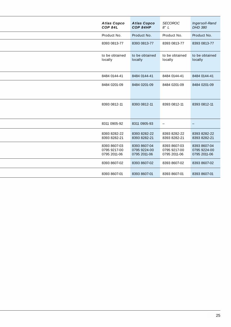
Atlas Copco Atlas Copco SECOROC Ingersoll-RandCOP 84L COP 84HP 8” L DHD 380
Product No. Product No. Product No. Product No.
8393 0813-77 8393 0813-77 8393 0813-77 8393 0813-77
to be obtained to be obtained to be obtained to be obtainedlocally locally locally locally
8484 0144-41 8484 0144-41 8484 0144-41 8484 0144-41
8484 0201-09 8484 0201-09 8484 0201-09 8484 0201-09
8393 0812-11 8393 0812-11 8393 0812-11 8393 0812-11
8311 0905-92 8311 0905-93 – –
8393 8282-22 8393 8282-22 8393 8282-22 8393 8282-228393 8282-21 8393 8282-21 8393 8282-21 8393 8282-21
8393 8607-03 8393 8607-04 8393 8607-03 8393 8607-040795 9217-00 0795 9224-00 0795 9217-00 0795 9224-000795 2011-06 0795 2011-06 0795 2011-06 0795 2011-06
8393 8607-02 8393 8607-02 8393 8607-02 8393 8607-02
8393 8607-01 8393 8607-01 8393 8607-01 8393 8607-01

26
1
2
7
12
13
Auxiliary tools Product NumberWrench for pilot bit .......................................... 8484 0211-42Wrench for extension rods .............................. 0795 9063-00Wrench for guide device.................................. 8484 0211-60Grouting device ............................................... 7989 1509-00
Further information on pages 30-31
3
5
8
8a
10
9
11
6
4
Type of hammer
Description Specifications
Shank adapter R38
Flushing devicePacking (included, 2 pcs)
1 Driving sleeve For shank adapter with male threadWrench flats 65 mm R38 - R38T38 - R38T45 - R38
2 Spacer
3 Cup spring 3 pcs required
4 Driving cap Complete, O.D. 145 mmOutlet bend, separate
5 Adapter sleeve Wrench flats 110 mm
6 Starting casing tube Length 250 mm
7 Casing tube Threaded, for ODEX 76TR.H. thread, O.D. 88.9 mmWall thickness 5.5 mm★ Length 1220 mm
7 Casing tube Threaded, for ODEX 76WO.D. max. 89 mm,I.D. min. 78 mmWall thickness min. 4.5 mm
8 Extension rod, R38 ★ Length 1220 mm (4)
8a Extension rod Length 280 mm
9 Coupling sleeve D = 55 mm, L = 170 mm
10 Wing coupling D = 76 mm, L = 180 mm
11 Guide device
12 Reamer ★★ Reaming diameter 96 mm (3 25/32)
13 Pilot bit ★★ Diameter 70 mm (2 3/4)
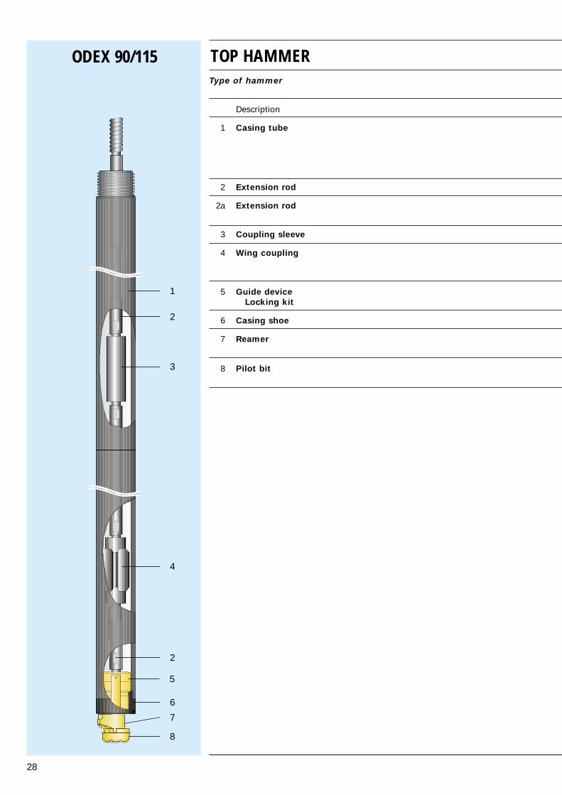
TOP HAMMERODEX 76

27
ODEX 76T ODEX 76W
★ Other lengths of casings and extension rods, are available as standard.
Lenght Casing tube Extension rodin mm (in) Part No. Part Number
1830 (6”) 8393 8179-48 7854 4318-302440 (8”) 8393 8179-14 7854 4324-303050 (10”) 8393 8179-22 7854 4331-30
★ Buttons No. x size mm
Gauge FrontReamer 3 x 10 —Pilot bit 6 x 12.7 5 x 10
Length Extension rodin mm (in) Part Number
1830 (6”) 7854 4318-302440 (8”) 7854 4324-303050 (10”) 7854 4331-30
Atlas Copco Atlas Copco Other types of Atlas Copco Atlas Copco Other types of BBE 57-01 COP 1238ME top-hammer with BBE 57-01 COP 1238ME top-hammer with
male thread male threadadapter adapter
Product No. Product No. Product No Product No Product No Product No
7804 7505-01 7804 3598-01 — 7804 7505-01 7804 3598-01 —
7801 0001-00 — — 7801 0001-00 — —0795 1806-00 0795 1806-00
— 7989 1512-00 7989 1512-00 — 7989 1512-00 7989 1512-00— — 7989 1519-00 — — 7989 1519-00— — 7989 1517-00 — — 7989 1517-00
8484 0140-54 8484 0140-54 8484 0140-54 8484 0140-54 8484 0140-54 8484 0140-54
0384 3595-00 0384 3595-00 0384 3595-00 0384 3595-00 0384 3595-00 0384 3595-00
8484 0211-57 8484 0211-57 8484 0211-57 8484 0211-57 8484 0211-57 8484 0211-578484 0211-59 8484 0211-59 8484 0211-59 8484 0211-59 8484 0211-59 8484 0211-59
8484 0140-49 8484 0140-49 8484 0140-49 8484 0140-51 8484 0140-51 8484 0140-51
8393 8179-05 8393 8179-05 8393 8179-05 8393 8179-05 8393 8179-05 8393 8179-05
8393 8179-06 8393 8179-06 8393 8179-06 — — —
— — — to be obtained to be obtained to be obtainedlocally locally locally
7854 4312-30 7854 4312-30 7854 4312-30 7854 4312-30 7854 4312-30 7854 4312-30
7854 4302-20 7854 4302-20 7854 4302-20 7854 4302-20 7854 4302-20 7854 4302-20
7994 3655-00 7994 3655-00 7994 3655-00 7994 3655-00 7994 3655-00 7994 3655-00
7994 3076-00 7994 3076-00 7994 3076-00 7994 3076-00 7994 3076-00 7994 3076-00
7989 4076-00 7989 4076-00 7989 4076-00 7989 4076-00 7989 4076-00 7989 4076-00
7588 5096-40 7588 5096-40 7588 5096-40 7588 5096-40 7588 5096-40 7588 5096-40
7588 4070-40 7588 4070-40 7588 4070-40 7588 4070-40 7588 4070-40 7588 4070-40
28
5
ODEX 90/115
8
7
6
2
4
1
3
TOP HAMMERType of hammer
Description
1 Casing tube
2 Extension rod
2a Extension rod
3 Coupling sleeve
4 Wing coupling
5 Guide deviceLocking kit
6 Casing shoe
7 Reamer
8 Pilot bit
2

29
ODEX 90 ODEX 115
Specifications Product No. Specifications Product No
Threaded, for ODEX 90 Threaded, for ODEX 115R.H. thread, O.D. 114.3 mm R.H. thread, O.D. 139.7 mmWall thickness 6.3 mm Wall thickness 6.3 mmLength 1220 mm 8393 8191-56 Length 1220 mm 8393 0816-35Length 1530 mm 8393 8191-55 Length 3050 mm 8393 0816-34
R32, R38, T38 T45, T51
R38 R51Length 280 mm 7854 4302-20 Length 780 mm 8393 0816-18
R32, R38, T38 T45, T51
R38-R32 3744 9006-21 R51-T45 8393 0816-19R38-R38 3744 9006-22 R51-T51 8393 0816-20R38-T38 3744 9006-23
8393 8602-23 8393 0816-010795 2011-01 0795 2011-02
Surface hardened 8393 8191-42 Surface hardened 8393 8178-04
Reaming diameter 8393 8602-22 Reaming diameter 8393 0815-95123 mm (4 27/32) 152 mm (6)
Diameter 8393 8602-21 Diameter 8393 0815-9490 mm (3 9/16) 115 mm (4 1/2)
Buttons No. x size mm
Gauge FrontReamer 4x12.7 1x11Pilot bit 8x11 5x11
Buttons No. x size mm
Gauge FrontReamer 4x14.5 1x12.7Pilot bit 8x14.5 8x14.5

Fishing tools
Sleeves
For catching Part No.API Reg pin
2 3/8 4” DTH hammer A = 89 8484 0210-952 3/8 76 mm pipe A = 81.5 8484 0210-962 3/8 89 mm pipe A = 94 8484 0210-973 1/2 6” DTH hammer A =138 8484 0210-993 1/2 114 mm pipe A =120 8484 0210-98
PikesFor catching
API Reg pin
2 3/8 Drill pipes A = 26 B = 45C = 75D = 91 8484 0210-93
3 1/2 Drill pipes A = 34B = 60C = 76D = 114 8484 0210-94
Diameter Part No.
ODEX 76 64 – 76 8484 0211-42ODEX 76/90 76 – 90 8484 0211-14ODEX 90 85 – 100 8484 0211-41ODEX 115 105 – 115 8484 0211-17ODEX 140 127 – 140 8484 0211-18ODEX 165 150 – 165 8484 0211-05ODEX 190 178 – 190 8484 0211-47
For extension rodsR38 0795 9093-00
R38 0795 9063-00
For drill pipes and other equipment with flatsWrenchflats
65 8484 0211-0095 8484 0211-02
110 8484 0211-62120 8484 0211-36140 8484 0211-44
30
Wrenches
For ODEX pilot bitsand down-the-hole bits
Auxiliary tools
Part No.
ODEX 90–165 D = max. 225 8484 0211-12T = 110
ODEX 190 D = max. 300 8484 0211-13T = 140
Other ODEX tools
Welding fixtures
D
C
B
A
A

Part No.
Lifting plugs, swivelling
3 1/2 API Reg box 8484 0213-24
Lifting plugs, fixed2 3/8 API Reg box 8484 0213-283 1/2 API Reg box 8484 0213-323 1/2 API Reg pin 8484 0213-41
Lifting slings for drill pipes
Drill pipe length Drill pipe Ø
3000 mm 89 8484 0213-056000 mm 89 8484 0213-133000 mm 114 8484 0213-066000 mm 114 8484 0213-14
Lifting slings for ODEX equipmenttogether with 3 m casing
ODEX 115 8484 0213-01ODEX 140 8484 0213-02ODEX 165 8484 0213-03ODEX 190 8484 0213-09
Part No.
ODEX 76 8484 0211-60ODEX 90 8484 0211-08ODEX 115 8484 0211-06ODEX 140 8484 0211-04ODEX 165 8484 0211-07ODEX 190 8484 0211-09
(see also illustration on page 33)
31
Wrenches
For ODEX guide devices
Wrench flats Hose connection Part No.
ODEX 76T-G2 97 mm R1” 7989 1509-00
ODEX 90T-G2 65 mm R1” 8484 0140-45
ODEX 115T-G2 140 mm R1” 8484 0140-24
ODEX 140T-G2 140 mm R1” 8484 0140-46
ODEX 165T-G2 140 mm R1” 8484 0140-68
Grouting device (DTH)
Lifting tools
Auxiliary tools

32
Wall L Ø Part No.thickness mm ft in mm
2 3/8 API Reg 6.3 mm 2100 6’ 11” 76 8484 0143-682 3/8 API Reg 6.3 mm 2000 6’ 3/4” 76 8484 0143-18
2 3/8 API Reg 6.3 mm 2100 6’ 11” 89 8484 0144-402 3/8 API Reg 6.3 mm 2000 6’ 6 3/4” 89 8484 0141-712 3/8 API Reg 6.3 mm 1900 6’ 2 3/4” 89 8484 0144-362 3/8 API Reg 6.3 mm 1800 5’ 11” 89 8484 0144-372 3/8 API Reg 6.3 mm 1700 6’ 7” 89 8484 0144-382 3/8 API Reg 6.3 mm 1600 5’ 3” 89 8484 0144-47
3 1/2 API Reg 8.8 mm 1800 5’ 11” 114 8484 0144-413 1/2 API Reg 8.8 mm 1700 5’ 7” 114 8484 0144-423 1/2 API Reg 8.8 mm 1600 5’ 3” 114 8484 0144-48
Locking kitDescription Dimensions Qty. Part No.
ODEX 90T/W-G2 Locking kit compl. 0795 2011-01-Bearing ball Ø 9.5 6 (12) 0517 1116-00-Spring pin Ø 10x15 2 (4) 0795 2002-01-Locking pin Ø 10x50 2 (4) 0102 0419-00
ODEX 115T/W-G2 Locking kit compl. 0795 2011-02-Bearing ball Ø 9.5 10 (18) 0517 1116-00-Spring pin Ø 10x15 2 (4) 0795 2002-01-Locking pin Ø 10x60 2 (2) 0102 0423-00
ODEX 140T/W-G2 Locking kit compl. 0795 2011-03-Bearing ball Ø 11 12 (18) 0517 1166-00-Spring pin Ø 12x20 2 (4) 0795 2002-02-Locking pin Ø 12x70 2 (2) 0102 0476-00
ODEX 165T/W-G2 Locking kit compl. 0795 2011-04-Bearing ball Ø 11 14 (21) 0517 1166-00-Spring pin Ø 12x20 2 (4) 0795 2002-02-Locking pin Ø 12x80 2 (2) 0102 0478-00
ODEX 190W-G2 Locking kit compl. 0795 2011-05-Bearing ball Ø 13 14 (21) 0517 1100-16-Spring pin Ø 14x20 2 (4) 0795 2002-03-Locking pin Ø 14x100 2 (2) 0795 2001-05
ODEX 240W-G2 Locking kit compl. 0795 2011-06-Bearing ball Ø 13 18 (27) 0517 1100-06-Spring pin Ø 14x20 2 (4) 0795 2002-03-Locking pin Ø 14x120 2 (2) 0795 2001-06
Start drill pipes

33
ODEX G2 Ball locking system
Assembly
1. Coate the pilot pin thread withAtlas Copco thread grease.
2. Thread the pilot bit into the guidedevice by hand.
3. Insert a lock pin into one of theholes for the locking system (Fig.1).
Make sure the lock pin is in bottomposition of hole.
4. Hammer spring pin into position.Use suitable size of mandrel toprevent damages on guide device,when lock pin get near the edge ofthe guide device.
5. Seat the spring pin against the lockpin.
6. Load bearing balls into the holewithout lock pin. Use the mandrelto guide the bearing balls into thegroove (Fig. 2). Fill groove with noof bearing balls as shown on nextpage.
7. Load the last lock pin into hole (Fig. 3).
8. Hammer spring pin into position.
9. Before start to drill, tighten up thepilot thread by using a suitablepilot bit wrench.
Dissassembly
1. Open up the pilot bit thread byusing a suitable pilot bit wrench.
2. Remove all spring- and lock pins, byusing a hammer and suitable mandrel (Fig. 4).
3. The bearing balls will then easily beguided out of the groove, by using a nylon strap or flexible steel wire(Fig. 5).
4. Unthread the pilot bit.
5. Free the reamer from the pilot bit.
Bearing ballSpring pinLock pin
Fig. 1
Fig. 2
Fig. 3
Fig. 4 Fig. 5
Nylon strap
Mandrel

K
G
F
E
D
B
IJ
LH
C
A
M
34
Dimensions ODEX 90-240
A Pilot Bit, length 53 61 72 78 84 86
B Reamer, length 55 62 70 80 90 100
C Guide device, protrusion 13 16 15 18 14 15
D Guide device, length 125 140 155 170 190 190
E DTH-hammer, length - - - - - 317
F Guide sleeve, length 225 225 ** 250 *** ****
G Start drill pipe, - - - - -see page 32
H Discharge head, connection diameter 76 102 102 127 127 127
I Discharge head,connection length 200 230 250 250 270 270
J Discharge head,diameter 194 219 254 254 300 300
K Discharge head,built-in length 155 180 180 205 205 205
L Adapter sleeve*built-in length 105 110 110 110 - -
M Casing shoe, length 80 77 90 90 110 110
*) Only threaded casing**) See page 18***) See page 22****) See page 24
OD
EX
90
OD
EX
115
OD
EX
140
OD
EX
165
OD
EX
190
Ref. Description Dimensions in mm
OD
EX
240
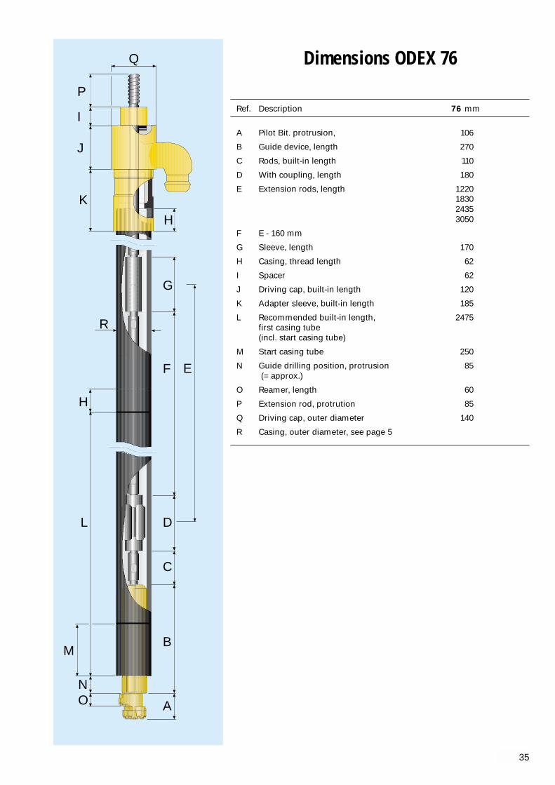
Ref. Description 76 mm
A Pilot Bit. protrusion, 106
B Guide device, length 270
C Rods, built-in length 110
D With coupling, length 180
E Extension rods, length 1220 183024353050
F E - 160 mm
G Sleeve, length 170
H Casing, thread length 62
I Spacer 62
J Driving cap, built-in length 120
K Adapter sleeve, built-in length 185
L Recommended built-in length, 2475first casing tube(incl. start casing tube)
M Start casing tube 250
N Guide drilling position, protrusion 85(= approx.)
O Reamer, length 60
P Extension rod, protrution 85
Q Driving cap, outer diameter 140
R Casing, outer diameter, see page 5
Q
P
I
J
K
H
G
F E
D
C
B
A
R
H
L
ON
M
35
Dimensions ODEX 76

Drilling depthsObtained casing driving depth with ODEX depends on factors such as type of formation, available drilling equipment, and the drill crew’s experience.Experience has shown that below and even deeper holes can be drilled with ODEX.
ODEX 90 115 140 165 190 240
Maximum hole depth in soil, (m) 60 100 100 100 100 100
Air pressureMaximum recommended air pressure is 14 bar.
36
Torque requirementDrill rigs must have sufficuent torque for drilling with ODEX.This table shows minimum required torque for the various ODEX sizes.
ODEX 90 115 140 165 190 240
Minimum torque, Nm 900 2000 3000 4000 >5500 >5500
Rotation speedRotation speed depends on the size of the ODEX bit and also on the formation being drilled. The rotation speed may have to be varied as the formation changes. The table shows recommendedrotation speeds for the various ODEX sizes.
ODEX 90 115 140 165 190 240
Speed, r/min 20-30 20-25 15-20 15-20 10-15 10-15
Recommendations DTH Hammers

37

38
Conversion factors
This unit Times Equals
Lengthmm (millimetres) x 0.001 = mcm (centimetres) x 0.01 = mdm (decimetres) x 0.1 = mkm (kilometres) x 1000 = min (inches) x 25.4 = mmft (feet) x 0.305 = myd (yard) x 0.914 = mmiles x 1609 = m
PowerkW (kilowatts) x 1000 = WHorsepower, metric x 735.5 = WHorsepower, U.K. x 745.7 = Wft.lbf/sec x 1.36 = WBtu/h x 0.29 = W
Volumel (litres) x 0.001 = m3
ml (millilitres) x 0.001 = ldm3 (cubic decimetres) x 1.0 = lcm3 (cubic centimetres) x 1.0 = mlmm3 (cubic millimetres)x 0.001 = mlin3 (cubic inches) x 16.39 = mlft3 (cubic feet) x 28.316 = lImperial gallon x 4.546 = lU.S. gallon x 3.785 = lOunces (Imp. fluid oz) x 28.41 = mlOunces (U.S. fluid oz) x 29.57 = mlPints (U.S. lig.) x 0.4732 = lQuarts (U.S. liq) x 0.9463 = lyd3 (cubic yards) x 0.7646 = m3
ForcekN (kilonewton) x 1000 = Nkp (kilopond) x 9.81 = Nkgf (kilogramme force) x 9.81 = Nlbf (pound force) x 4.45 = N
Torquekpm (kilopondmetres) x 9.81 = Nmlbf in (poundforce/inch) x 0.11 = Nmlbf ft (poundforce/foot) x 1.36 = Nm
This unit Times Equals
Mass (weight)g (grammes) x 0.001 = kgt (tonnes, metric) x 1000 = kggrains x 0.0648 = goz (ounce) x 28.35 = glb (pounds) x 0.4536 = kgtons (long, US) x 1016 = kgtons (U.K.) x 1016 = kgtons (short) x 907 = kg
Speedkm/h (kilometres/hour) x 0.2777 = m/sm/s x 3.6 = km/hmph (miles/hour) x 0.45 = m/smph x 1.61 = km/hft/s (foot/second) x 0.3048 = m/sft/s /foot/second) x 18.29 = ft/minft/min (foot/minute) x 0.3048 = m/min
Frequencyblows/minute x 0.017 = HzkHz (kiloHertz) x 1000 = Hzr/min (rev./minute) x 0.01667 = r/sdegrees/second x 0.1667 = r/minradians/second x 0.1592 = r/s
Pressurebar x 100 = kPabar x 100 000 = Pakp/cm2 x 0.98 = baratm (atmospheres) x 1.01 = barpsi (pounds/in2) x 6.895 = kPapsi x 0.06895 = bar
Areamm2 (square mm) x 0.000001 = m2
cm2 (square cm) x 0.0001 = m2
in2 (square inches) x 645 = mm2
ft2 (square feet) x 0.929 = m2
yd2 (square yards) x 0.8361 = m2
Acres x 4047 = m2
Square miles x 2.590 = km2

0141-71 30 9,17,320141-90 27 10,12,18
20,22,240141-91 44 10,12,18
20,22,240143-18 25 15,320143-68 21 7,15,320144-36 29 9,17,320144-37 28 11,17,19,320144-38 27 11,19,320144-40 31 9,13,19,320144-41 49 13,23,25,320144-42 48 13,21,23,320144-47 25 19,320144-48 44 21,320201-01 15 6,8,14,160201-02 11 6,8,14,160201-03 25 7,9,15,170201-04 18 8,10,16,180201-05 31 9,11,17,190201-08 35 10,12,18
20,22,240201-09 60 13,21,23,250201-91 18 6,8,10,14,160201-92 23 8,10,16,180210-93 14 300210-94 21 300210-95 12 300210-96 10 300210-97 4,5 300210-98 18 300210-99 28 300211-00 5,5 7,9,11,15,17
19,300211-02 8 11,13,19
21,23,300211-04 14,5 11,16,19,310211-05 20 13,21,26,300211-06 15 9,17,310211-07 21 13,21,310211-08 12 7,15,310211-09 22,5 23,310211-12 4 300211-13 5 300211-14 13 7,15,300211-17 14,5 9,17,300211-18 18 11,19,300211-27 15 7,150211-29 14,5 9,170211-31 18 11,190211-33 20 13,210211-36 10,5 300211-41 13 300211-42 13 26,300211-44 14 9,11,13,300211-45 23 230211-47 23,300211-57 15 270211-59 0,5 270211-60 2,5 26,310211-62 10 300213-01 11,5 310213-02 13,5 310213-03 16 310213-05 9 310213-06 9,5 310213-09 23 310213-13 10 310213-14 10,5 310213-24 12,5 310213-28 5,5 310213-32 9 310213-41 9,5 31
39
Weights and Cross Index
102
0419-00 0,06 320423-00 0,06 320476-00 0,08 320478-00 0,1 32
384
3595-00 0,16 27
517
1100-06 0,01 321100-16 0,01 321116-00 0,003 321166-00 0,005 32
795
1806-00 0,02 272001-05 0,1 322001-06 0,1 322002-01 0,01 322002-02 0,01 322002-03 0,03 322005-01 0,1 7,152005-02 0,1 7,152011-01 0,1 7,15,322011-02 0,1 9,17,322011-03 0,3 11,19,322011-04 0,3 13,21,322011-05 0,5 23,322011-06 0,6 25, 329063-00 6,2 269214-00 0,02 9,179215-00 0,03 11,199216-00 0,025 13,21,239217-00 0,03 23, 259224-00 0,03 259235-00 0,07 13,21,239236-00 0,05 11,13,19,219237-00 0,01 9,11,17,199279-00 0,01 7,9,15,17
3744
9006-21 3,1 299006-22 3,1 299006-23 3,1 29
7588
4070-40 3 275096-40 1 27
7801
0001-00 2,2 27
7804
3598-01 4,5 277505-01 6,8 27
7854
4302-20 2 27,294312-30 10 274318-30 14,5 274324-30 17,8 274331-30 25 27
7989
1509-00 10,5 26,31
1512-00 5,3 271517-00 5,3 271519-00 5,3 274076-00 6,2 27
7994
3076-00 2,6 273655-00 1,7 27
8311
0903-21 23 7,150905-14 27,1 7,9,15,170905-50 38 9,11,17,190905-60 57 11,190905-70 57 11,13,19,210905-80 95 13,21,230905-92 130 23,250905-93 158 25
8393
0812-11 25,5 250813-77 28,5 250815-94 7,4 290815-95 2,6 290816-01 11 290816-18 290816-19 290816-20 290816-34 63 290816-35 21 298178-03 1,5 178178-04 1,5 8,9,17,298178-07 29 88178-15 61 98178-49 40,6 88178-56 20,3 88178-75 60 98179-05 2,8 278179-06 14 278179-14 28 278179-22 36 278179-48 21 278179-53 3,2 218179-54 3,2 12,13,218179-55 29 128179-63 43,5 128179-71 58 128179-89 87 138179-99 85 138180-29 25 108180-37 38 108180-45 50 108180-52 75 118180-88 79 118180-93 2,4 198180-94 2,4 10,11,198182-01 4,1 238182-02 4,1 238182-21 7,2 258182-22 7,2 258191-01 17 68191-11 25,5 68191-21 34 68191-31 51 78191-41 1,1 158191-42 1,1 6,7,15,298191-54 52 78191-55 25,5 298191-56 20,0 298602-01 3,6 7,158602-02 1,5 7,158602-03 7 7,15
8602-04 7 7,158602-06 7 7,158602-07 7 7,158602-21 3,6 298602-22 1,6 298602-23 10,2 298603-01 7,4 9,178603-02 2,6 9,178603-03 12 9,178603-04 12 9,178603-05 12 9,178603-06 12 9,178604-01 13 11,198604-02 4,5 11,198604-03 20,5 11,198604-04 17 11,198604-05 20,5 11,198604-06 20,5 11,13,198605-01 19,3 13,218605-02 7 13,218605-03 35 13,218605-04 35 13,218605-05 35 13,218605-06 32,5 13,218606-01 27,5 238606-02 10 238606-03 45,5 238606-04 45,5 238606-05 45,5 238607-01 50,5 258607-02 18 258607-03 68 258607-04 68 25
8484
0140-22 0,2 9, 170140-23 2,7 90140-24 12 9, 310140-29 0,3 9, 170140-30 0,3 7, 150140-31 0,5 11, 190140-32 0,5 110140-33 0,5 13,210140-34 0,9 230140-37 3,6 110140-38 2,3 70140-39 4,1 130140-40 9 7,150140-41 17,5 11,190140-42 22 230140-45 10,5 7,310140-46 14 11,310140-49 6,7 270140-51 6,2 270140-54 2 270140-55 2,0 230140-56 2,0 230140-57 0,2 230140-58 3,0 7,9,11,13
15,17,1921,23
0140-59 1,0 7,150140-61 8,1 7,150140-62 1,5 9,170140-64 0,2 9,11,13
17,19,210140-65 1,0 11,190140-66 13,210140-68 17 13,310141-43 11,5 9,170141-44 13 11,190141-49 6,7 11,190141-50 20,5 13,210141-55 14 8,10,16,18
Product Weight Pagenumber kg
Product Weight Pagenumber kg
Product Weight Pagenumber kg
Product Weight Pagenumber kg

Atlas Copco Geotechnical Drilling and Explorationwww.atlascopco.com
69
91 0
65
4 01
b
Mär
sta,
Sw
eden
, 20
08.0
5©
Co
pyr
igh
t 20
08, A
tlas
Co
pco
Cra
eliu
s A
B, M
ärst
a, S
wed
en. A
ny u
nau
tho
rize
d u
se o
r co
pyi
ng
of
the
con
ten
ts o
r an
y p
art
ther
eof
is p
roh
ibit
ed. T
his
ap
plie
s in
par
ticu
lar
to t
rad
emar
ks, m
od
el d
eno
min
atio
ns,
Pro
du
ct N
o.s
an
d d
raw
ing
s. Il
lust
rati
on
s an
d p
ho
tos
in t
his
bro
chu
re m
ay s
ho
w e
qu
ipm
ent
wit
h
op
tio
nal
ext
ras.
Sp
ecifi
cati
on
s an
d e
qu
ipm
ent
sub
ject
s to
ch
ang
e w
ith
ou
t n
oti
ce. C
on
sult
yo
ur
Atl
as C
op
co C
ust
om
er C
ente
r fo
r sp
ecifi
c in
form
atio
n.


