AVINASH PRAKASHPROFESSOR/DT
IRIMEE JAMALPUR

60 % passengers carried by the entire IR travel on thesuburban system.
Perform an extremely arduous duty almost throughout theday
The reliability of suburban services is a very critical factor inits operation
Attention to the braking system and under gear due tofrequent starts/stops
Corrosion repairs (coastal areas , fish transportation)

SPECIAL MAINTENANCE INSTRUCTION FORUNIFORM PERIODICITY OF MAINTENANCESCHEDULES FOR EMU (AC & DC) & MEMU
COACHESNO. RDSO / PE / SMI / EMU / 0037 -2007(Rev. 0)
APRIL-2007 a

PERIODICITY OF MAINTENANCE OF CIL ENGINE, ELECTRICS & CONTROLS BRAKE EQUIPMENT.
i. Trip Schedule - 7 days ii. Monthly Schedule - 1 month ± 3 days iii. Quarterly Schedule - 3 months ± 3 days iv. Half yearly Schedule - 6 months ± 5 days v. Eighteen monthly Schedule - 18 months ± 7 days POH PERIODICITY OF MAJOR ITEMS i. CIL engine E-Check - 18000 (which is eqvt.36months.)
ii. Traction motors - 18 months. iii. Traction Alternator - 36 months. iv. Compressor - 18 months. v. Coach body and under gear - 18 months. The power pack is E-Checked by Cummins
Pune,TA,TM,Compressor,maintained by Shed and coach POH is done by carriage workshop.

SPECIAL MAINTENANCE INSTRUCTION FORUNIFORM PERIODICITY OF MAINTENANCESCHEDULES FOR EMU (AC & DC) & MEMU
COACHESNO. RDSO / PE / SMI / EMU / 0037 -2007(Rev. 0)
APRIL-2007AC EMU and MEMUs
Sl.no. Type of Schedule EMU MEMU Remarks
1 TI 10 days 10 days
2 IA 45 days 45 DAYS
3 IA1 90 days 90 days
4 IA2 135 days 135 days
5 IC 180 days 180 days + UT on axles
6 AOH 1 year 1 year
7 POH 1 ½ year 1 ½ year

SCHEDULE PERIODICITY
ROLLING-IN-EXAMINATION DAILY
NIGHT EXAMINATION DAILY IN ALL 18 STABLING
DEPOTS.
TI SCHEDULE 10 DAYS.
IA SCHEDULE 45 DAYS.
IC SCHEDULE 180 DAYS
WASHING 15 DAYS
ULTRASONIC TESTING OF
AXLES
6 MONTHS.
POH 2 YEARS ( 1st POH ) 1 ½ YEAR
REMAINING POH
Codal life of EMU/MEMU is 25 years

CLEANING SCHEDULE :- Washing of exteriors & wet mopping of interiors shall be done during trip inspection and broomingmust be done at night stabling points every day.
ITEMS FOR DAILY CHECKING AT NIGHT STABLING POINTS :-
• Visual Inspection of wheels for cracks, checking of axle boxes, its cover and bolts
• Check axle guide springs, bolsters spring swings links, bogie frame and all brake riggings. Also check schaku couplers and side buffers.
• Check brake blocks for their position and replacements if required
• Drain main reservoirs.
• Go through the motorman logbook and attend the defects booked during the run
• Passenger amenities and all safety items attention

Broken seats and seats frame Worn out / broken chequered plates in doorways Missing glass and louver shutter including complete window
frame Missing doors Worn out / tilted foot step in MEMUs Vestibule plates and shutters in MEMUs Missing overhead handles and hand rails Missing of seat handle/luggage rack Proper working of compartment Light & Fan

Adequate numbers of Stabling lines without pit suitable for one unit length
Small accommodation having skeleton maintenance line staff with a store room, toilet and one office room be provided at the stabling point of MEMUs with communication facilities with the homing shed, TLC, PPO, Sr.DEE etc
Yard illumination of the stabling lines should be provided
Necessary infrastructure for daily inspection of MEMU rakes at stabling point for carrying the safety checks during night stabling should be provided. Safai-wallas for dry sweeping of
rakes may be arranged

Almost all electrical and mechanical equipments for MEMUare different than in electric locomotives.
Inspection line, washing lines, stabling line lengths toaccommodate 12/16 car rakes not readily available.
Shunting neck of at least 400 m. is also required on bothends
Electric loco sheds already over-loaded

The inter distance between the two car-shedsshould be of the order of 400 Kms for MEMUsheds, if being planned for exclusively MEMUservices.
Since EMU services are planned keeping in viewthe peak requirement of traffic and intensity ofservices, the inter-distance between the two EMUcar sheds should be based on theseconsiderations alone and no value for it can belaid, this being guided solely by service need.

The proposed facilities and the layout of the EMUshed does not include facilities required for workslike POH, Rehabilitation of the EMUs, Completerecabling, Pneumatic Pipe Lines replacement,Major Corrosion Repairs, Accident Damages etc,which should be carried out in the central workshop on the railway. Removal of Wheels from theAxle, Re-tyring of Wheels is not proposed in theSheds since it may be economical & convenient tosend the Wheel Sets to the Work Shops wherefacilities already exist.

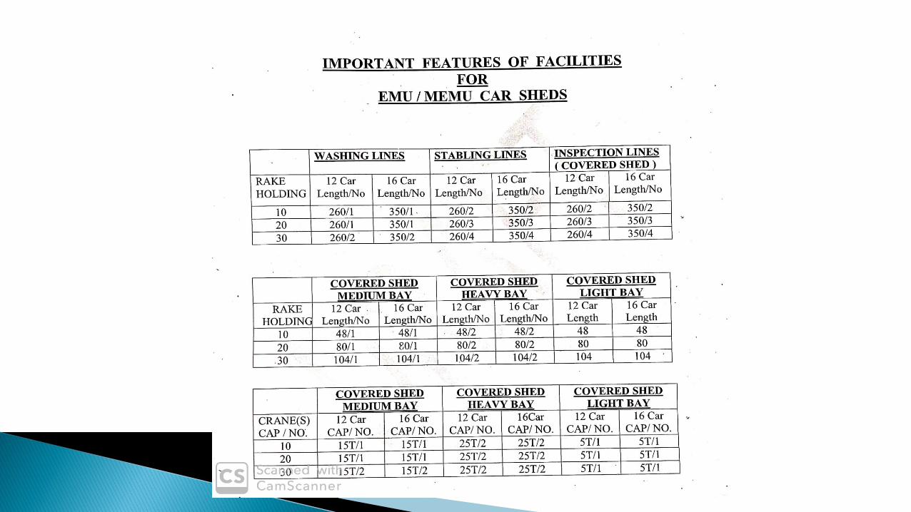
Requirement in Shed for 30/20/10 rakes for catering to the Schedules
• Inspection Lines (4/3/2 Nos.) • Washing Lines (2/1/1 Nos.) • Stabling Lines (4/3/2 Nos.) • Heavy Lifting Bay • Medium Lifting Bay • Light Lifting Bay • Shed for Pit Wheel Lathe for EMU Tyre Turning • Mechanical & Electrical Equipment repair/Overhaul
Sections

• PPO & Supervisors' Cabins• Machine Shop• Sr. DEE's Administrative Office & Technical Section• Yard Layout• Stores Depot & Oil Godown• Services (Compressor Room, Sub-Station, Power
Distribution, transport )• Amenities ( Time Office, Cycle Stand, Water Coolers,
Lockers, Toilets, Canteen )

Provision of sunken floor facilitates easier/comfortableaccess and attention to under frame mounted equipmentsresulting to better quality with lesser efforts and time.
In this shed, there shall be provision for pneumatic lines,welding points and at least one drilling point for eachInspection line.

Washing lines laid with concrete and provided with good drainage, suitable hydrant points and adequate supply of water for washing the bogies and under gearing of the EMU’s should be provided.
High level platform should be provided on both the sides of the washing lines for easy movements of staff for sweeping inside the coaches.
Arrangements be made to isolate over-head line over the high level platform to avoid accidental touch of the water jet with the live wires.

The bay is provided with two 25T overhead electrical cranes.
The distance between track centre to track centre has beenkept 11 meters to facilitate the coach movement in liftedcondition by EOT crane from one end to other endlongitudinally while other lifted coaches are kept in betweenthese two lines on trassels.
Cross-track facility for movement of bogies

Provision of pit as well as plain floor alternately shall be madeof suitable length
5 Nos. of 25 T hydraulic jacks shall be provided in this bay forlifting of body and rolling out the bogie etc. This bay shallalso be provided with 12/8/8 sets of accommodation bogiesfor 30/20/10 rake holdings.
1 set of lifting beams for the EMU body shall be kept in thebay

Battery charging room Axle box roller bearing section Tool room Brake and pneumatic equipment section Welding section Machine shop Traction motor bearing and pinion section Bogie assembly section Traction motor repair and overhaul section

Provided for overhaul and repairs to bogies, wheel sets, axleboxes, gears, brake rigging, brake cylinders, traction motorrepairs, smoothing reactor repairs.
Provision of 2 pits of 30m length each separated by a plainfloor of 10m length to facilitate Material/Staff movementshould be made.
The above Bay shall be equipped with two 15 T EOT Cranesand will be Primary Shop for Overhauling and AssemblingBogies along with the Traction Motors. The Pits will work asAssembly Bay for the under gear equipment.
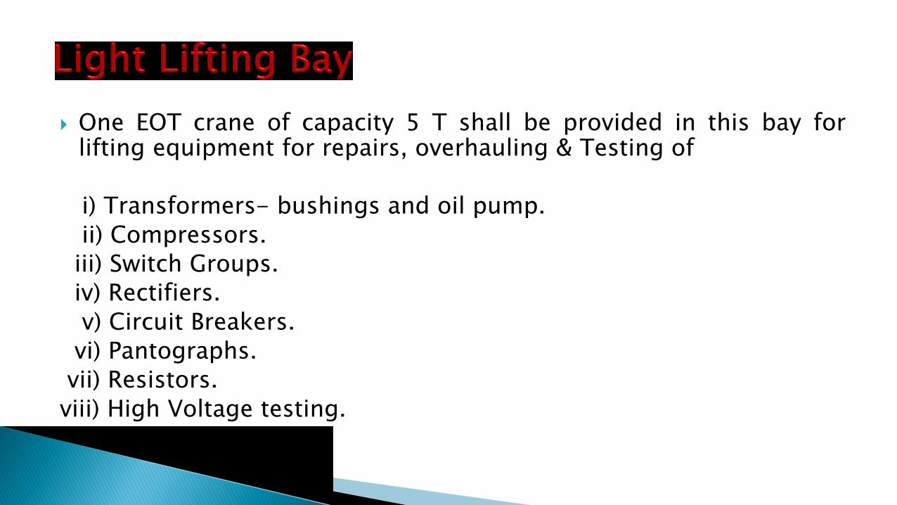
One EOT crane of capacity 5 T shall be provided in this bay forlifting equipment for repairs, overhauling & Testing of
i) Transformers- bushings and oil pump.
ii) Compressors.
iii) Switch Groups.
iv) Rectifiers.
v) Circuit Breakers.
vi) Pantographs.
vii) Resistors.
viii) High Voltage testing.
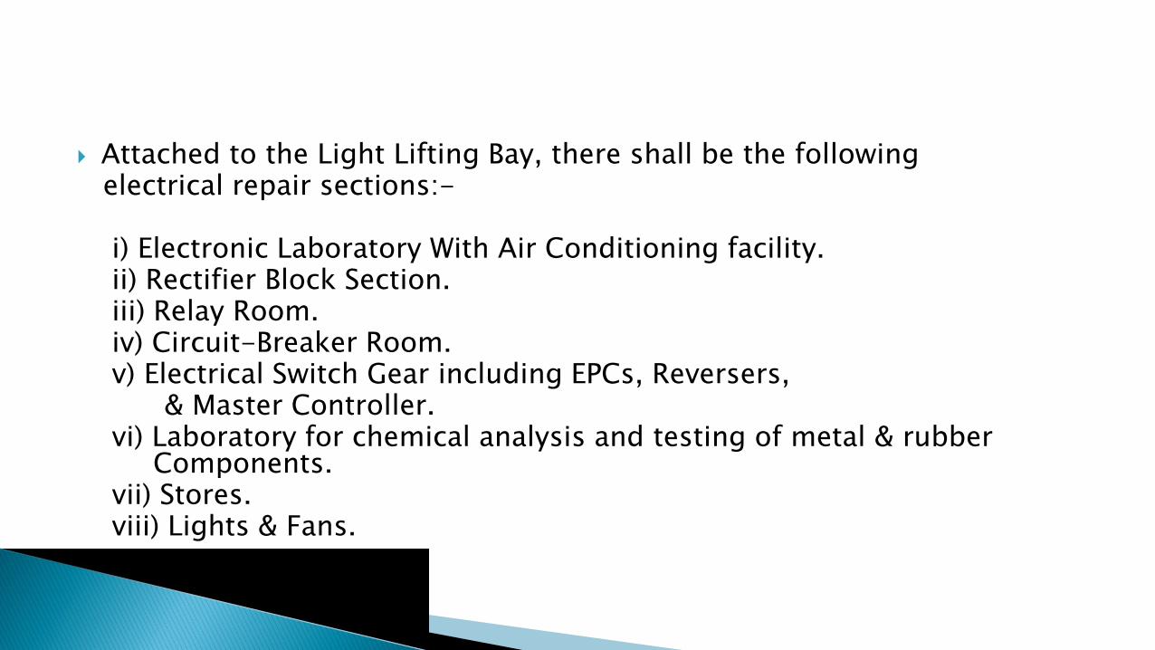
Attached to the Light Lifting Bay, there shall be the followingelectrical repair sections:-
i) Electronic Laboratory With Air Conditioning facility.ii) Rectifier Block Section.iii) Relay Room.iv) Circuit-Breaker Room.v) Electrical Switch Gear including EPCs, Reversers,
& Master Controller.vi) Laboratory for chemical analysis and testing of metal & rubber
Components.vii) Stores.viii) Lights & Fans.

Compressed Air supply:- Two screw type air compressorseach of capacity 600 cfm, 9 kg/cm2 are provided in thecompressor room.
Electric sub-station :- A separate sub-station of indoor typewith 2-x 1000 KVA transformers for supply of 415V, 3 phase,50 Hz should be provided for electrical services.
Two D.G Sets of 250 KVA rating shall be provided to take careof emergency loads.
Material handling transport system

LIST-1 : MACHINE TOOLS (GENERAL PURPOSE MACHINES). CompressorDG SetPortable transformer welding Plant
LIST-2: SPECIAL PURPOSE MACHINES AND TOOLS. Pit Wheel LathePinion Extractor
LIST-3:TESTING AND MEASURING INSTRUMENTS AND PANELS.
LIST-4: LIFTING, HANDLING AND TRANSPORT EQUIPMENT. Cranes 25T,15T,5T
LIST-5: WORK BENCHES, LOCKERS ETC.
Important M&Ps

GROUND FLOOR OF ADMINISTRATIVE GROUND FLOOR OF CENTRAL BUILDING BUILDING
1. RECTIFIER BLOCK SECTION 1. MACHINE SHOP 2. CIRCUIT BREAKER ROOM 2 .TOOL ROOM 3. ELECTRICAL SWITCH GEARS SUCH AS EPCs, 3. BATTERY CHARGING ROOM
REVERSERS, MASTER CONTROLLERS etc4. RELAY ROOM 4. WELDING SECTION 5. ELECTRONIC LABORATORY WITH 5. BRAKE & PNEUMATIC EQUIPMENT SECTION
AIR CONDITIONING FACILTY6. LABORATORY FOR CHEMICAL ANALYSIS & TESTING 6. AXLE BOX ROLLER BEARING SECTION
FOR METAL & RUBBER COMPONENTS 7. CUSTODY STORE 7. TRACTION MOTOR ROLLER BEARING SECTION
8. LIGHTS & FANS 8. SHIFT SUPERVISOR’S STORE

Man Power and Benchmarks
Wednesday, August 14, 2019Selction of service 27
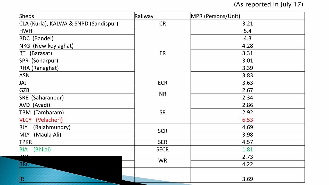
Sheds Railway MPR (Persons/Unit)CLA (Kurla), KALWA & SNPD (Sandispur) CR 3.21HWH
ER
5.4BDC (Bandel) 4.3NKG (New koylaghat) 4.28BT (Barasat) 3.31SPR (Sonarpur) 3.01RHA (Ranaghat) 3.39ASN 3.83JAJ ECR 3.63GZB
NR2.67
SRE (Saharanpur) 2.34AVD (Avadi)
SR2.86
TBM (Tambaram) 2.92VLCY (Velacheri) 6.53RJY (Rajahmundry)
SCR4.69
MLY (Maula Ali) 3.98TPKR SER 4.57BIA (Bhilai) SECR 1.81BCT
WR2.73
BRC 4.22
IR 3.69
(As reported in July 17)

3.21
5.4
4.3 4.28
3.313.01
3.39
3.833.63
2.67
2.34
2.86 2.92
6.53
4.69
3.98
4.57
1.81
2.73
4.22
3.69
0
1
2
3
4
5
6
7
Sheds
MPR (Persons/Unit)All India average is 3.69.Yard stick 7 man per unit

NALLASOPARA VIRAR
DN LLUPLL
UP ML
DN ML
SCHEMATIC LAY OUT PLAN OF EMU CARSHED VIRAR
DCOS Store
36x24+
18x8m
Admn bldg
42x17.28m
Canteen and
Running Room
30x18m
Lifting shed
140x24.6m
Inspection
shed 280x22.9m
Substation in Phase-
2
30x12
Sub
Station
30x12m
Comp. room
11x8m
UG tank,
Filtration and
pump house
30x16m
Residential complex,
Type-I-12
Type-II-12
Type-III-24
Type-V-1
Multi-purpose Hall-1
Automatic washing line-
700mManual washing line-700m
Test track
Stabling lines= 2x6= 12 nos. 15 car
Pit wheel lathe shed
35x12m
Main bldg G+1
116x11m
Tech Premises-1
70x7m
Tech Premises-2
70x7m
Ext Lifting shed (S) in
Phase-II 140x24.6
Futu
re e
xte
nsio
n
of
Insp
ecti
on
shed
for
15
car
70
x2
2.9
Extn Lifting shed(N) in
Phase-II
149.5x24.6m
Drop table shed in
Phase-II
70x24.295m
Inspection shed in Phase-II
280x22.9m
Training
Centre/ rest
house in Phase-II-
G+1
42X18m
Futu
re p
ath
way
20
mFutu
re
exte
nsio
n o
f Lif
ting s
hed
fo
r 1
5 c
ar
70
x2
4.6
Future Inspection shed
350x22.9m
Main bldg in Phase-II
64x11m
DC
OS S
tore
in
Phase-II-
36
x1
2m
Future paint shop
Pointsman Room
STP
Future Tech
Premises
TM /TFR shed in Phase-II
112x13.415m
Bogie repair shed in
Phase-II
149.5x8.99m
2S L 1
S L 2
S L 3
S L 4
S L 5
S L 6
AWL
O H
TANK
Pointsman Room
ETP
Proposed location for parking stand

STABLING YARD AT EMU CARSHED VR
1. Stabling yard has 06 lines. Each
line accommodates two 15 car
rakes.
2. One Test Track .
3. Two washing lines (Manual &
Automatic).
4. Stabling yard has provision of
pathways on both sides of each line
for maintenance staff.

INSPECTION SHED

UNDER FLOOR WHEEL LATHE
CNC Based Under Floor Wheel
Lathe supplied by M/s. SCULFORT
equipped with a winch device & Chip
crusher with automatic conveyor .
Automatic metal turnings conveyor
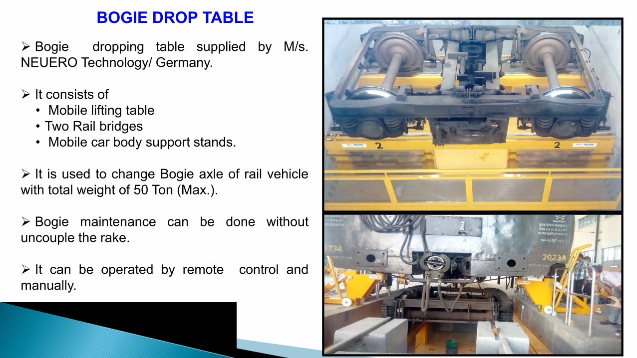
BOGIE DROP TABLE
➢ Bogie dropping table supplied by M/s.
NEUERO Technology/ Germany.
➢ It consists of
• Mobile lifting table
• Two Rail bridges
• Mobile car body support stands.
➢ It is used to change Bogie axle of rail vehicle
with total weight of 50 Ton (Max.).
➢ Bogie maintenance can be done without
uncouple the rake.
➢ It can be operated by remote control and
manually.

AUTOMATIC WASHING PLANT
➢ PLC base automatic washing plant is installed for
exterior washing of EMU.
➢ Plant is automatically started as soon as its
sensors detect rake
➢ One rake washing is carried out in 30 minutes.
➢ MMI is provided to monitor the various data of
plant
➢ 08 rakes washing is carried out daily.
➢ There are four stages of washing:
▪ Pre wet.
▪ Detergent spraying & scrubbing
▪ Fresh water scrubbing
▪ Final rinsing with RO water
PUMP &RO PLANT
AUTO. WASHING PLANT LINE

MANUAL WASHING PLANT
➢ Manual washing Plant is comprised of 3 nos. high
pressure pumps.
➢ Exterior and interior manual washing is carried out.
➢ Manual washing line has length to accommodate
2x15 coach trains.
➢ Platforms is constructed on both sides of washing
line to enable staff to carry out the job without fatigue.
➢ The washing line is provided on RCC slab to avoid
collection of water on the track. Drainage is provided
for used water to reach the Effluent Treatment Plant
(ETP).
MANUAL WASHING PLANT
MANUAL WASHING LINE

➢ Administrative Block to accommodate the office
of the Sr.DEE and other officers, technical
assistants, drawing office and IT centre.
➢ Training centre building to train motor man and
maintenance staff.
➢ Rest house accommodation for trainees,
supervisor and officers on first floor.
➢ Two substations and compressor room.
➢ Under ground tank and water filtration plant.
➢ Security check posts and signal huts on both
end of shed i.e. NSP and VR.

RUNNING ROOM & CANTEEN BUILDING
Running rooms for Motormen & Guards along with canteen for carshed staff is constructed
covering the area of 1080 sqm.
It has easy access from sheds as well as Administrative building and Training Centre.
➢ Canteen is well furnished and has the
seating capacity of 152 staff.
➢ Running rooms accommodated 13
well furnished rooms (27 beds) for the
Motormen and Guards.
RUNNING ROOM &CANTEEN BUILDING

Electrical training center / Virar