

7/28/2019 Backscatter Radar
http://slidepdf.com/reader/full/backscatter-radar 1/7
1
A compressed sensing approach fordetection of explosive threats at standoff
distances using a Passive Array of ScattersJose Angel Martinez-Lorenzo, Yolanda Rodriguez-Vaqueiro and Carey M. Rappaport
ALERT Center of Excellence for Department of Homeland Security,
Gordon CenSSIS, Northeastern University Boston (MA), USA
{ jmartine ; rappapor }@ece.neu.edu
Oscar Rubinos Lopez, Antonio Garcia Pino
Dept. of Signal Theory and Communications, University of Vigo, Vigo, Spain
{ oscar ; agpino }@com.uvigo.es
Abstract—This work presents a new radar system concept,working at millimeter wave frequencies, capable of de-tecting explosive related threats at standoff distances. Thesystem consists of a two dimensional aperture of randomlydistributed transmitting/receiving antenna elements, and aPassive Array of Scatters (PAS) positioned in the vicinityof the target. In addition, a novel norm one minimizationimaging algorithm has been implemented that is capableof producing super-resolution images. This paper alsoincludes a numerical example in which 7.5 mm resolutionis achieved at the standoff range of 40 m for a workingfrequency of 60 GHz.
Index Terms—radar, compressive sensing, millimeter
wave imaging.
I. INTRODUCTION
DURING the last decade, new systems based on
Millimeter-Wave-Radar technology have been de-
ployed on airport checkpoints all around the world [1].
Millimeter wave systems are preferred to X-ray systems
[2]-[4], for this particular application, because the former
do not use ionizing radiation. These systems have been
proved to be successful on finding explosives concealed
underclothing; the success of this technology is mainly
due to the short range between the sensing components
of the system and the person under test. A new importantchallenge arises when the same technology is desired
for threat detection at standoff distances [5]-[8], which
include ranges running between ten to fifty meters.
In this work, a novel configuration based on an array
of randomly distributed transmitting/receiving antennas,
located on a two dimensional aperture, is used to scan
a person at standoff distances. In order to improve
the resolution of the radar system, a Passive Array of
Scatters (PAS) is also placed near the target region.
Under this configuration, the non-linear imaging problem
can be linearized if the field produced by the two dimen-
sional array and the PAS is accurately known across the
imaging region. As a result, the imaging problem can
be written into a matrix form. The sensing matrix, with
coefficients representing the propagation from the target
to the sensor establishes the linear relationship between
the reflectivity value of a pixel on the target and the field
measured on the array of receivers. For the particular
case in which the number of pixels in the image is much
larger than the number of sensors, the sensing matrix
may become singular and difficult to invert.A new approach, based on compressive sensing [9]-
[16], can be used to invert the matrix if two conditions
are satisfied: 1) the image can be represented by a
sparse representation of customized basis functions; and
2) the sensing matrix complies with the mathematical
Restricted Isometric Property (RIP) condition. If both
conditions are satisfied, the image can be reconstructed
by solving a convex problem.
This paper shows how this imaging algorithm has been
used to achieve a resolution of 1.5 wavelengths, or 7.5
mm at 60 GHz. The proposed algorithm can accurately
reconstruct the reflectivity values of both weak dielec-
tric scatterers, such as explosives, including Tri-Nitro-Toluene (TNT), and strong scatters, like metallic pipes,
concealed under clothing.
I I . SYSTEM CONFIGURATION
A. System Concept of operation
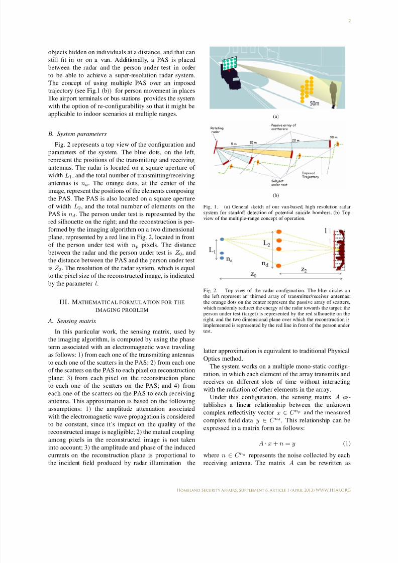
The proposed system configuration is shown sche-
matically in Fig. 1. It is composed of an inexpensive,
high-resolution radar system that can distinguish foreign
1
Homeland Security Affairs, Supplement 6, Article 1 (April 2013) WWW.HSAJ.ORG
7/28/2019 Backscatter Radar
http://slidepdf.com/reader/full/backscatter-radar 2/7
2
objects hidden on individuals at a distance, and that can
still fit in or on a van. Additionally, a PAS is placed
between the radar and the person under test in order
to be able to achieve a super-resolution radar system.
The concept of using multiple PAS over an imposed
trajectory (see Fig.1 (b)) for person movement in places
like airport terminals or bus stations provides the systemwith the option of re-configurability so that it might be
applicable to indoor scenarios at multiple ranges.
B. System parameters
Fig. 2 represents a top view of the configuration and
parameters of the system. The blue dots, on the left,
represent the positions of the transmitting and receiving
antennas. The radar is located on a square aperture of
width L1, and the total number of transmitting/receiving
antennas is na. The orange dots, at the center of the
image, represent the positions of the elements composing
the PAS. The PAS is also located on a square apertureof width L2, and the total number of elements on the
PAS is nd. The person under test is represented by the
red silhouette on the right; and the reconstruction is per-
formed by the imaging algorithm on a two dimensional
plane, represented by a red line in Fig. 2, located in front
of the person under test with n p pixels. The distance
between the radar and the person under test is Z 0, and
the distance between the PAS and the person under test
is Z 2. The resolution of the radar system, which is equal
to the pixel size of the reconstructed image, is indicated
by the parameter l.
III . MATHEMATICAL FORMULATION FOR THE
IMAGING PROBLEM
A. Sensing matrix
In this particular work, the sensing matrix, used by
the imaging algorithm, is computed by using the phase
term associated with an electromagnetic wave traveling
as follows: 1) from each one of the transmitting antennas
to each one of the scatters in the PAS; 2) from each one
of the scatters on the PAS to each pixel on reconstruction
plane; 3) from each pixel on the reconstruction plane
to each one of the scatters on the PAS; and 4) from
each one of the scatters on the PAS to each receivingantenna. This approximation is based on the following
assumptions: 1) the amplitude attenuation associated
with the electromagnetic wave propagation is considered
to be constant, since it’s impact on the quality of the
reconstructed image is negligible; 2) the mutual coupling
among pixels in the reconstructed image is not taken
into account; 3) the amplitude and phase of the induced
currents on the reconstruction plane is proportional to
the incident field produced by radar illumination the
(a)
(b)
Fig. 1. (a) General sketch of our van-based, high resolution radarsystem for standoff detection of potential suicide bombers. (b) Topview of the multiple-range concept of operation.
Fig. 2. Top view of the radar configuration. The blue circles on
the left represent an thinned array of transmitter/receiver antennas;the orange dots on the center represent the passive array of scatters,which randomly redirect the energy of the radar towards the target; theperson under test (target) is represented by the red silhouette on theright, and the two dimensional plane over which the reconstruction isimplemented is represented by the red line in front of the person undertest.
latter approximation is equivalent to traditional Physical
Optics method.
The system works on a multiple mono-static configu-
ration, in which each element of the array transmits and
receives on different slots of time without interacting
with the radiation of other elements in the array.
Under this configuration, the sensing matrix A es-
tablishes a linear relationship between the unknown
complex reflectivity vector x ∈ C np and the measured
complex field data y ∈ C nd . This relationship can be
expressed in a matrix form as follows:
A · x + n = y (1)
where n ∈ C nd represents the noise collected by each
receiving antenna. The matrix A can be rewritten as
2
Homeland Security Affairs, Supplement 6, Article 1 (April 2013) WWW.HSAJ.ORG
7/28/2019 Backscatter Radar
http://slidepdf.com/reader/full/backscatter-radar 3/7
3
the product of two matrices: 1) E b, which is a di-
agonal matrix accounting for the background incident
field produced by a single transmitting/receiving antenna
and PAS on the reconstruction plane; and 2) P , which
is a full matrix accounting for the propagation from
each point on the reconstruction plane to each trans-
mitting/receiving antenna after passing though the PAS.After applying some algebraic operations, the coeffi-
cients aij of the sensing matrix A can be expressed as
follows:
aij =
nd p=1
e−j2k|ri−r
p |e−j2k|r
p−r
j|
(2)
where k is the free space wave number; ri is a vector
indicating the position of the i-th transmitting/receiving
antenna; rj is a vector indicating the position of the
j-th pixel in the reconstruction plane; and r p is a vector
indicating the position of p-th scatter in the PAS.
B. Imaging algorithm using compressive sensing
approach
The proposed radar system is designed in accordance
with the compressive sensing theory [9]-[16]. In order
to apply such principles for standoff detection of ex-
plosive related-threats, certain mathematical conditions
must be satisfied by the sensing matrix A and the
reconstructed reflectivity image x. These conditions can
be summarized as follows [13]: 1) the sensing matrix
must satisfy the Restricted-Isometry-Property condition,
which is related to the independency of the columns
of the matrix; and 2) the unknown reflectivity vector
must accept a sparse representation as a solution, whichrelated to the number of non-zero entries on the solution
vector. The parameters of the systems can be modified
until these two conditions are satisfied; the optimized
parameters include the following: aperture length of
the radar, aperture length of the PAS, resolution in
the reconstruction plane, number of antennas on the
radar aperture, number of scatters in the PAS, working
frequency, separation between the radar and the PAS,
separation between the PAS and the target. In this work,
this optimization is done manually, but it is expected
that in further research contributions such optimization
process should be automatized.
If the two aforementioned conditions are satisfied,
then the reconstruction of the unknown vector can be
performed with a small number of measurements (trans-
mitting/receiving antennas) by solving the following
convex problem [15]:
minx1
s.t. Ax = y (3)
where x1
represents the norm-one of the vector x.
In the particular case where x is not sparse, the problem
can still be solved if one can find a discretized functional
W , in which a sparse representation x p of the unknown
vector x can be found through the following relation-
ship: x p = W x. Therefore, the “Compressive Sensing”
problem can be now solved by the following problem:
minW x1 s.t. Ax = y (4)
A Total Variation (TV) functional W is used in this
particular work [15]. The TV functional W computes
and adds the two directional gradients of the image x
for each pixel; thus achieving a sparse representation x pof the original image x.
IV. NUMERICAL EXAMPLES
A. Radar configuration
The imaging principles described in the previous sec-
tion are evaluated on two different scenarios (see Table
I): configuration #1, in which the distance between theradar and person under test is ten meters; and configu-
ration #2, in which the distance between the radar and
person under test is forty meters. Table I also summarizes
all the parameters used for the numerical simulations. It
is important to realize that in order to increase the range
by a factor of four, from ten to forty meters, the length of
the radar aperture must also be increased by a factor of
four, and the number of antennas in such aperture must
also be increased by a 60% factor, from five to eight
hundred. The size and the number of scatters of the PAS
is the same for both configurations, leading to the same
system resolution of 7.5 millimeters. For the simulations
in this work, a uniform white noise of 25 dB of signalto noise ratio is considered; and the working frequency
of the system is 60 GHz.
PARAMETER CONFIG. #1 CONFIG. #2
Z 0 2000λ = 10 m 8000λ = 40 m
Z 2 250λ = 1.25 m 250λ = 1.25 m
L1 80λ = .4 m 320λ = 1.6 m
L2 250λ = 1.25 m 250λ = 1.25 m
na 500 800
nd 1000 1000
l 7.5 mm 7.5 mm
TABLE IPARAMETERS FOR THE NUMERICAL EXAMPLES.
B. Target specifications
In order to test the feasibility of the system, a projec-
tion into a two dimensional plane of the three dimen-
sional geometry, –a person with attached explosives– is
3
Homeland Security Affairs, Supplement 6, Article 1 (April 2013) WWW.HSAJ.ORG
7/28/2019 Backscatter Radar
http://slidepdf.com/reader/full/backscatter-radar 4/7
4
used as ground truth for the imaging algorithm. This
two dimensional simplification of the three dimensional
problem allows for a fast reconstruction using only one
frequency for the radar configuration, and its extension
to the three dimensional problem can be easily imple-
mented in the future.
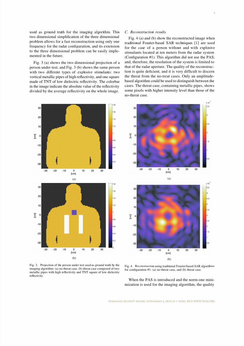
Fig. 3 (a) shows the two dimensional projection of a
person under test; and Fig. 3 (b) shows the same person
with two different types of explosive stimulants: two
vertical metallic pipes of high reflectivity, and one square
made of TNT of low dielectric reflectivity. The colorbar
in the image indicate the absolute value of the reflectivity
divided by the average reflectivity on the whole image.
(a)
(b)
Fig. 3. Projection of the person under test used as ground truth by theimaging algorithm: (a) no-threat case, (b) threat case composed of twometallic pipes with high reflectivity and TNT square of low dielectricreflectivity.
C. Reconstruction results
Fig. 4 (a) and (b) show the reconstructed image when
traditional Fourier-based SAR techniques [1] are used
for the case of a person without and with explosive
stimulants located at ten meters from the radar system
(Configuration #1). This algorithm did not use the PAS;
and, therefore, the resolution of the system is limited to
that of the radar aperture. The quality of the reconstruc-
tion is quite deficient, and it is very difficult to discern
the threat from the no-treat cases. Only an amplitude-
based algorithm could be used to distinguish between the
cases. The threat case, containing metallic pipes, shows
some pixels with higher intensity level than those of the
no-threat case.
(a)
(b)
Fig. 4. Reconstruction using traditional Fourier-based SAR algorithmsfor configuration #1: (a) no-threat case, and (b) threat case.
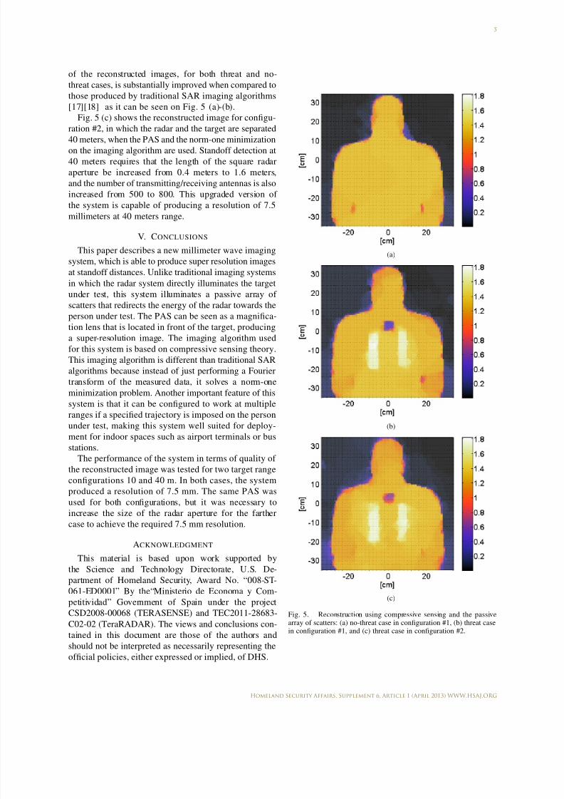
When the PAS is introduced and the norm-one mini-
mization is used for the imaging algorithm, the quality
4
Homeland Security Affairs, Supplement 6, Article 1 (April 2013) WWW.HSAJ.ORG
7/28/2019 Backscatter Radar
http://slidepdf.com/reader/full/backscatter-radar 5/7
5
of the reconstructed images, for both threat and no-
threat cases, is substantially improved when compared to
those produced by traditional SAR imaging algorithms
[17][18] as it can be seen on Fig. 5 (a)-(b).
Fig. 5 (c) shows the reconstructed image for configu-
ration #2, in which the radar and the target are separated
40 meters, when the PAS and the norm-one minimizationon the imaging algorithm are used. Standoff detection at
40 meters requires that the length of the square radar
aperture be increased from 0.4 meters to 1.6 meters,
and the number of transmitting/receiving antennas is also
increased from 500 to 800. This upgraded version of
the system is capable of producing a resolution of 7.5
millimeters at 40 meters range.
V. CONCLUSIONS
This paper describes a new millimeter wave imaging
system, which is able to produce super resolution images
at standoff distances. Unlike traditional imaging systems
in which the radar system directly illuminates the target
under test, this system illuminates a passive array of
scatters that redirects the energy of the radar towards the
person under test. The PAS can be seen as a magnifica-
tion lens that is located in front of the target, producing
a super-resolution image. The imaging algorithm used
for this system is based on compressive sensing theory.
This imaging algorithm is different than traditional SAR
algorithms because instead of just performing a Fourier
transform of the measured data, it solves a norm-one
minimization problem. Another important feature of this
system is that it can be configured to work at multiple
ranges if a specified trajectory is imposed on the person
under test, making this system well suited for deploy-
ment for indoor spaces such as airport terminals or bus
stations.
The performance of the system in terms of quality of
the reconstructed image was tested for two target range
configurations 10 and 40 m. In both cases, the system
produced a resolution of 7.5 mm. The same PAS was
used for both configurations, but it was necessary to
increase the size of the radar aperture for the farther
case to achieve the required 7.5 mm resolution.
ACKNOWLEDGMENT
This material is based upon work supported bythe Science and Technology Directorate, U.S. De-
partment of Homeland Security, Award No. “008-ST-
061-ED0001” By the“Ministerio de Economa y Com-
petitividad” Government of Spain under the project
CSD2008-00068 (TERASENSE) and TEC2011-28683-
C02-02 (TeraRADAR). The views and conclusions con-
tained in this document are those of the authors and
should not be interpreted as necessarily representing the
official policies, either expressed or implied, of DHS.
(a)
(b)
(c)
Fig. 5. Reconstruction using compressive sensing and the passivearray of scatters: (a) no-threat case in configuration #1, (b) threat casein configuration #1, and (c) threat case in configuration #2.
5
Homeland Security Affairs, Supplement 6, Article 1 (April 2013) WWW.HSAJ.ORG

7/28/2019 Backscatter Radar
http://slidepdf.com/reader/full/backscatter-radar 6/7
REFERENCES
[1] D. M. Sheen, D. L. McMakin, T. E. Hall, “Three-Dimensional Millimeter-Wave Imaging for Concealed Weapon Detection”, IEEE Transactions on Microwave Theory and Techniques, Vol.49, No. 9, pp. 1581-1592, September 2001.
[2] US patent 5181234, Steven W. Smith, “X-ray Backscatter Detec-tion System”, Issued 1993-01-19.
[3] R. F. Eilbert, Shi Shuanghe, “Improved imaging for X-ray inspec-tion systems”, IEEE Aerospace and Electronic Systems Magazine,Vol. 20, Issue 3, pp. 23-28, 2005.
[4] TSA X-ray Screening Technology Safety Reports:http://www.tsa.gov/research/reading/xray screening technologysafety reports march 2011.shtm
[5] J. A. Martinez-Lorenzo, F. Quivira and C. M. Rappaport, “SARimaging of suicide bombers wearing concealed explosive threats”,Progress In Electromagnetics Research, 125, pp. 255272, 2012.
[6] J. Fernandes, C. M. Rappaport, J. A. Martnez-Lorenzo, M. Hage-len, “Experimental results for standoff detection of concealed body-worn explosives using millimeter-wave radar and limited view ISAR processing”, 2009 IEEE Conference on Technologies
for Homeland Security (HST09). Waltham, MA, May 11-12, 2009.pp. 456-460.
[7] A. Angell, C. Rappaport,“Computational Modeling Analysis of Radar Scattering by Metallic Body-Worn Explosive Devices Cov-
ered with Wrinkled Clothing”, 2007 IEEE/MTT-S International Microwave Symposium. Honolulu, HI, June 3-8, 2007. pp. 1943-1946.
[8] K. B. Cooper, R. J. Dengler, N. Llombart, B. Thomas, G.Chattopadhyay, P. H. Siegel, “THz Imaging Radar for Standoff Personnel Screening”, IEEE Trans. Terahertz Science and Tech.,Vol.1, pp.169-182, Sept. 2011.
[9] E. Candes, J. Romberg, and T. Tao, “Robust Uncertainly Prin-ciples: Exact Signal Reconstruction from Highly Incomplete Fre-
quency Information”, IEEE Transactions on Information Theory,52, 2, February 2006, pp. 489-502.
[10] E. Candes, J. Romberg, and T. Tao, “Signal Recovery from Incomplete and Inaccurate Measurements”, Communications onPure and Applied Mathematics, 59, 2006, pp. 1207-1223.
[11] D. L. Donoho, “Compressed Sensing”, IEEE Transactions on Information Theory, 52, 4, April 2006, pp. 1289-1306.
[12] R.G. Baraniuk, “Compressive Sensing”, IEEE Signal Processing
Magazine, 24(4), pp.118-121, July 2007.[13] A. C. Fannjiang, T. Strohmer, and P. Yan, “Compressed RemoteSensing of Sparse Objects”, SIAM J. Imaging Sciences, Vol. 3,No. 3, 2010, pp. 595-618.
[14] M.D.Migliore, D.Pinchera, “Compressed Sensing in Electro-
magnetics: Theory, Applications and Perspectives”, Proc. of the EuCAP, Rome (Italy), 2011.
[15] S. Becker, J. Bobin, E. J. Candes, “NESTA: A Fast accurate first-order method for sparse recovery” Siam J. on Imaging Sciencies,Vol. 4, pp. 1-39.
[16] http://www-stat.stanford.edu/ candes/nesta/ [17] Y. Alvarez, J. A. Martinez, F. Las-Heras, C. M. Rappaport, “An
inverse Fast Multipole Method for geometry reconstruction usingscattered field information”. IEEE Transactions on Antennas and Propagation, Vol. 60, No. 7, pp. 3351-3360, July 2012.
[18] Y. Alvarez, J. A. Martinez-Lorenzo, F. Las-Heras and C. M.Rappaport. “An inverse fast multipole method for imaging ap-
plications”, IEEE Antennas and Wireless Propagation Letters,10:12591262, 2011.
6
Homeland Security Affairs, Supplement 6, Article 1 (April 2013) WWW.HSAJ.ORG

7/28/2019 Backscatter Radar
http://slidepdf.com/reader/full/backscatter-radar 7/7
ABOUT THE AUTHORS
Jose Angel Martinez-Lorenzo - [email protected]
Yolanda Rodriguez-Vaqueiro
Carey Rappaport - [email protected]
ALERT Center of Excellence for Department of Homeland Security,
Gordon CenSSIS, Northeastern University Boston (MA), USA
Oscar Rubinos Lopez - [email protected]
Antonio Garcia Pino - [email protected]
Dept. of Signal Theory and Communications, University of Vigo, Vigo, Spain
© 2013 IEEE and published here with permission. Homeland Security Affairs is anacademic journal available free of charge to individuals and institutions. Because thepurpose of this publication is the widest possible dissemination of knowledge, copiesof this journal and the articles contained herein may be printed or downloaded andredistributed for personal, research or educational purposes free of charge and
without permission. Any commercial use of this article is expressly prohibited without the written consent of the copyright holder, the Institute of Electrical andElectronics Engineers (IEEE). Homeland Security Affairs is the online journal of theNaval Postgraduate School Center for Homeland Defense and Security (CHDS).
http://www.hsaj.org


