

1
Ball Float Steam TrapUNA 45, UNA 46, UNA 46ADN 15, 20, 25, 40, 50, 65PN 40/Class 300
DescriptionFloat traps type UNA 45 are designed for removing conden-sate from steam or compressed air.Float traps type UNA 46 and UNA 46A are designed for remo-ving condensate from steam or other gases / gas mixtures.Equipment fitted with control unit SIMPLEX and SIMPLEX-P is operated and controlled by the float and the rolling ball. Equipment with this type of control unit is particularly suitable for cold condensate and cold distillates.The rolling ball of the control unit SIMPLEX-P is made of Perbunan® rubber, which ensures tight shut-off of the seat.Equipment with control unit DUPLEX may also be used for air venting the installation. This type of control unit is parti-cularly suitable for saturated steam systems. The control unit DUPLEX consists of a float operated rolling ball valve and a temperature dependent air-venting facility. Do not expose the membrane regulator capsule of the DUPLEX control unit to superheat conditions above 5 K.By means of the externally adjustable internal bypass it is possible to adjust a bypass passage that flows past the control unit.The equipment must only be used within the allowable pres-sure and temperature limits and only if the chemical and corrosive influences on the equipment are taken into account.
FunctionThe control unit opens the orifice as a function of the liquid level. A rising level results in a proportional opening of the equipment. The max. discharge capacity depends on the orifice size when the ball is completely lifted off its seat and the orifice is fully open.
Optional extrasVent hole and drain holeFloat-lifting lever allows the float to be manually lifted (for purging any dirt away from the seat area)Hand-vent valve allows manual air-venting the pipelineStrainerHorizontal flow direction (hr) from left to right (when viewed from the body end)Control unit SIMPLEX-P with Perbunan® rolling ballExternally adjustable inner bypassSightglass coverSpecial cover for installing measuring electrodes NRG 16-19 or NRG 16-27
End connectionsFlange EN 1092-1 B1 PN 40Flange ASME B 16.5 Class 150 RF, 300 RFScrewed sockets G: ISO 228/1Screwed sockets NPT: ASME B 16.11Socket-weld ends to DIN EN 12760Socket-weld ends ASME B 16.11 Class 3000Butt-weld ends via transition pieces to EN 12627, welded joint geometry ISO 9692-1 code number 1.3 (30° chamfer)Butt-weld ends via transition pieces ASME B 16.25 ASME B 36.10
Data Sheet 819345-00Issue Date: 03/14
v
hl
hr
MaterialsComponent part Type EN ASTM
Body
UNA 45, UNA 46 1.0460 A105
UNA 46A 1.4404 A182-F316L
Cover
UNA 45 sightglasscover / cover forinstalling electrodes
5.3103 A3951)
UNA 46 1.0619 A216-WCB
UNA 46A 1.4408 A351-CF8M
Body gasket, controlunit gasket
all Graphite CrNi
Other components all Stainless steel
1) Physical and chemical properties comply with EN grade. ASTM nearest equivalent grade is stated for guidance only.
UNA 45 hl, UNA 46 hl, UNA 46A hl
UNA 45 hl Sightglass cover
UNA 45 hl Cover for mounting electrodes
The different equipment versions allow you to adjust the flow direction of the equipment to the flow pattern of your installa-tion. The flow arrow must correspond to the direction of the fluid flow. The following positions of installation are possible:
v
hl
hr
v
hl
hr
“v” for installation in vertical pipework with downward flow
“hl” for horizontal left
“hr” for horizontal right
2
1
32 4
28 18 19 20
2713
16
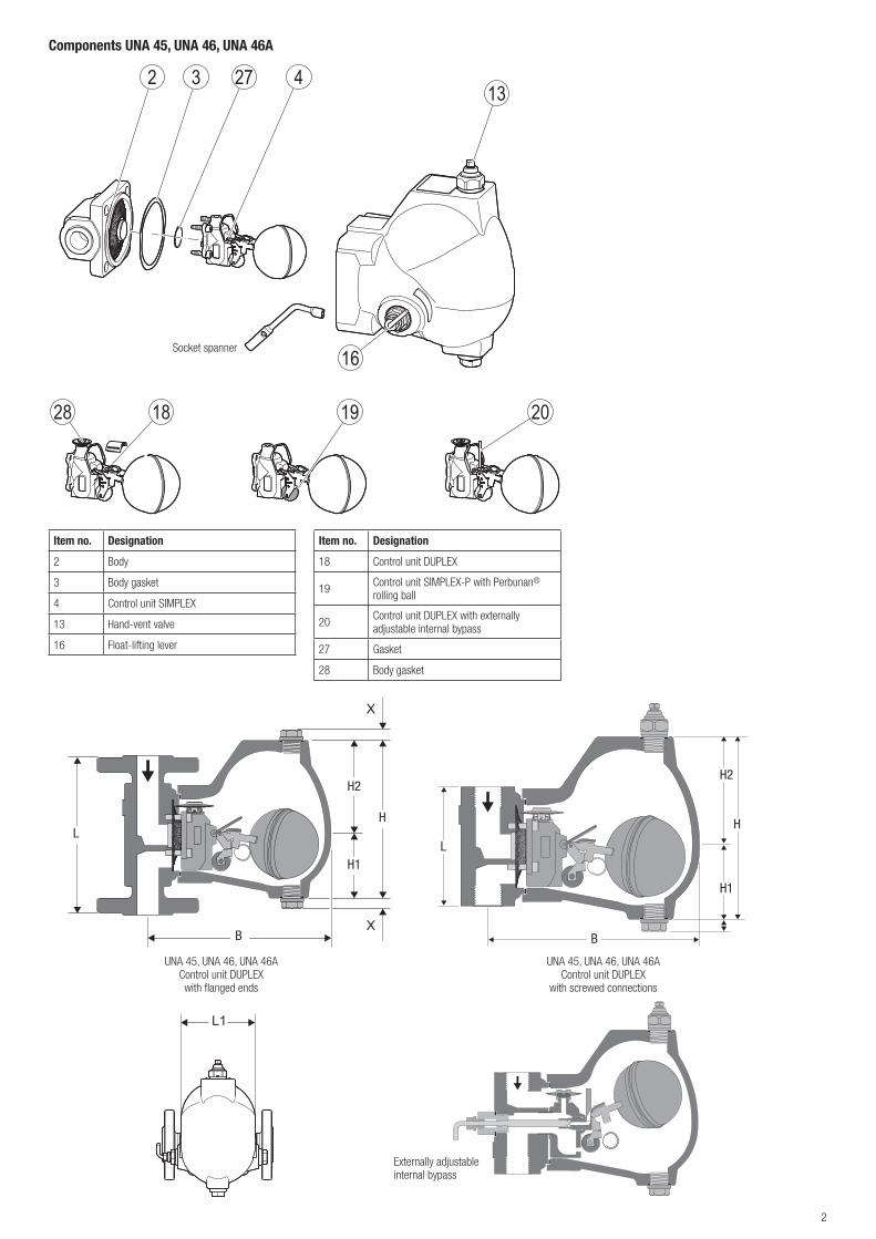
Components UNA 45, UNA 46, UNA 46A
Item no. Designation
2 Body
3 Body gasket
4 Control unit SIMPLEX
13 Hand-vent valve
16 Float-lifting lever
Socket spanner
Item no. Designation
18 Control unit DUPLEX
19 Control unit SIMPLEX-P with Perbunan® rolling ball
20 Control unit DUPLEX with externally adjustable internal bypass
27 Gasket
28 Body gasket
L1
X
X
L1
X
X
UNA 45, UNA 46, UNA 46AControl unit DUPLEXwith flanged ends
UNA 45, UNA 46, UNA 46AControl unit DUPLEX
with screwed connections
Externally adjustable internal bypass
H2
H1
H
B
LL
B
H2
H1
H
3
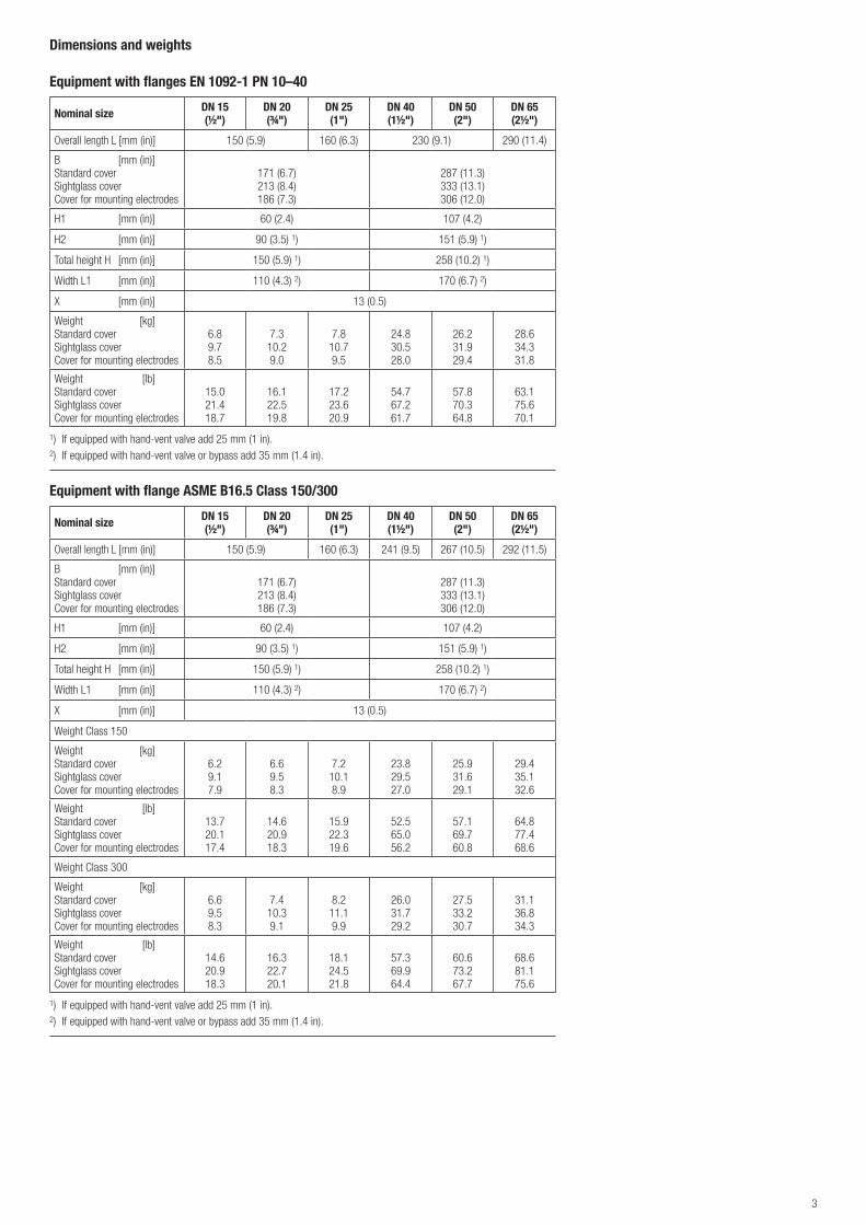
Equipment with flanges EN 1092-1 PN 10–40
Nominal size DN 15 (½")
DN 20 (¾")
DN 25 (1")
DN 40 (1½")
DN 50 (2")
DN 65 (2½")
Overall length L [mm (in)] 150 (5.9) 160 (6.3) 230 (9.1) 290 (11.4)
B [mm (in)]Standard coverSightglass coverCover for mounting electrodes
171 (6.7)213 (8.4)186 (7.3)
287 (11.3)333 (13.1)306 (12.0)
H1 [mm (in)] 60 (2.4) 107 (4.2)
H2 [mm (in)] 90 (3.5) 1) 151 (5.9) 1)
Total height H [mm (in)] 150 (5.9) 1) 258 (10.2) 1)
Width L1 [mm (in)] 110 (4.3) 2) 170 (6.7) 2)
X [mm (in)] 13 (0.5)
Weight [kg]Standard coverSightglass coverCover for mounting electrodes
6.89.78.5
7.310.29.0
7.810.79.5
24.830.528.0
26.231.929.4
28.634.331.8
Weight [lb]Standard coverSightglass coverCover for mounting electrodes
15.021.418.7
16.122.519.8
17.223.620.9
54.767.261.7
57.870.364.8
63.175.670.1
1) If equipped with hand-vent valve add 25 mm (1 in).2) If equipped with hand-vent valve or bypass add 35 mm (1.4 in).
Equipment with flange ASME B16.5 Class 150/300
Nominal size DN 15 (½")
DN 20 (¾")
DN 25 (1")
DN 40 (1½")
DN 50 (2")
DN 65 (2½")
Overall length L [mm (in)] 150 (5.9) 160 (6.3) 241 (9.5) 267 (10.5) 292 (11.5)
B [mm (in)]Standard coverSightglass coverCover for mounting electrodes
171 (6.7)213 (8.4)186 (7.3)
287 (11.3)333 (13.1)306 (12.0)
H1 [mm (in)] 60 (2.4) 107 (4.2)
H2 [mm (in)] 90 (3.5) 1) 151 (5.9) 1)
Total height H [mm (in)] 150 (5.9) 1) 258 (10.2) 1)
Width L1 [mm (in)] 110 (4.3) 2) 170 (6.7) 2)
X [mm (in)] 13 (0.5)
Weight Class 150
Weight [kg]Standard coverSightglass coverCover for mounting electrodes
6.29.17.9
6.69.58.3
7.210.18.9
23.829.527.0
25.931.629.1
29.435.132.6
Weight [lb]Standard coverSightglass coverCover for mounting electrodes
13.720.117.4
14.620.918.3
15.922.319.6
52.565.056.2
57.169.760.8
64.877.468.6
Weight Class 300
Weight [kg]Standard coverSightglass coverCover for mounting electrodes
6.69.58.3
7.410.39.1
8.211.19.9
26.031.729.2
27.533.230.7
31.136.834.3
Weight [lb]Standard coverSightglass coverCover for mounting electrodes
14.620.918.3
16.322.720.1
18.124.521.8
57.369.964.4
60.673.267.7
68.681.175.6
1) If equipped with hand-vent valve add 25 mm (1 in).2) If equipped with hand-vent valve or bypass add 35 mm (1.4 in).
Dimensions and weights
4
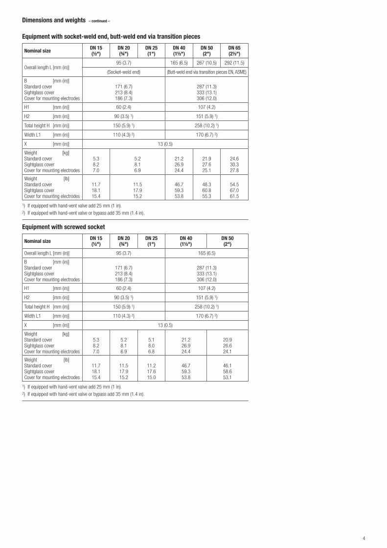
Equipment with socket-weld end, butt-weld end via transition pieces
Nominal size DN 15 (½")
DN 20 (¾")
DN 25 (1")
DN 40 (1½")
DN 50 (2")
DN 65 (2½")
Overall length L [mm (in)]95 (3.7) 165 (6.5) 267 (10.5) 292 (11.5)
(Socket-weld end) (Butt-weld end via transition pieces EN, ASME)
B [mm (in)]Standard coverSightglass coverCover for mounting electrodes
171 (6.7)213 (8.4)186 (7.3)
287 (11.3)333 (13.1)306 (12.0)
H1 [mm (in)] 60 (2.4) 107 (4.2)
H2 [mm (in)] 90 (3.5) 1) 151 (5.9) 1)
Total height H [mm (in)] 150 (5.9) 1) 258 (10.2) 1)
Width L1 [mm (in)] 110 (4.3) 2) 170 (6.7) 2)
X [mm (in)] 13 (0.5)
Weight [kg]Standard coverSightglass coverCover for mounting electrodes
5.38.27.0
5.28.16.9
21.226.924.4
21.927.625.1
24.630.327.8
Weight [lb]Standard coverSightglass coverCover for mounting electrodes
11.718.115.4
11.517.915.2
46.759.353.8
48.360.855.3
54.567.061.5
1) If equipped with hand-vent valve add 25 mm (1 in).2) If equipped with hand-vent valve or bypass add 35 mm (1.4 in).
Equipment with screwed socket
Nominal size DN 15 (½")
DN 20 (¾")
DN 25 (1")
DN 40 (1½")
DN 50 (2")
Overall length L [mm (in)] 95 (3.7) 165 (6.5)
B [mm (in)]Standard coverSightglass coverCover for mounting electrodes
171 (6.7)213 (8.4)186 (7.3)
287 (11.3)333 (13.1)306 (12.0)
H1 [mm (in)] 60 (2.4) 107 (4.2)
H2 [mm (in)] 90 (3.5) 1) 151 (5.9) 1)
Total height H [mm (in)] 150 (5.9) 1) 258 (10.2) 1)
Width L1 [mm (in)] 110 (4.3) 2) 170 (6.7) 2)
X [mm (in)] 13 (0.5)
Weight [kg]Standard coverSightglass coverCover for mounting electrodes
5.38.27.0
5.28.16.9
5.18.06.8
21.226.924.4
20.926.624.1
Weight [lb]Standard coverSightglass coverCover for mounting electrodes
11.718.115.4
11.517.915.2
11.217.615.0
46.759.353.8
46.158.653.1
1) If equipped with hand-vent valve add 25 mm (1 in).2) If equipped with hand-vent valve or bypass add 35 mm (1.4 in).
Dimensions and weights – continued –
5
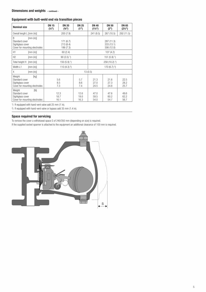
Equipment with butt-weld end via transition pieces
Nominal size DN 15 (½")
DN 20 (¾")
DN 25 (1")
DN 40 (1½")
DN 50 (2")
DN 65 (2½")
Overall length L [mm (in)] 200 (7.9) 241 (9.5) 267 (10.5) 292 (11.5)
B [mm (in)]Standard coverSightglass coverCover for mounting electrodes
171 (6.7)213 (8.4)186 (7.3)
287 (11.3)333 (13.1)306 (12.0)
H1 [mm (in)] 60 (2.4) 107 (4.2)
H2 [mm (in)] 90 (3.5) 1) 151 (5.9) 1)
Total height H [mm (in)] 150 (5.9) 1) 258 (10.2) 1)
Width L1 [mm (in)] 110 (4.3) 2) 170 (6.7) 2)
X [mm (in)] 13 (0.5)
Weight [kg]Standard coverSightglass coverCover for mounting electrodes
5.68.57.3
5.78.67.4
21.327.024.5
21.627.324.8
22.528.225.7
Weight [lb]Standard coverSightglass coverCover for mounting electrodes
12.318.716.1
12.619.016.3
47.059.554.0
47.660.254.7
49.662.256.7
1) If equipped with hand-vent valve add 25 mm (1 in).2) If equipped with hand-vent valve or bypass add 35 mm (1.4 in).
Dimensions and weights – continued –
Space required for servicingTo remove the cover a withdrawal space S of 240/350 mm (depending on size) is required.If the supplied socket spanner is attached to the equipment an additional clearance of 100 mm is required.
S
6
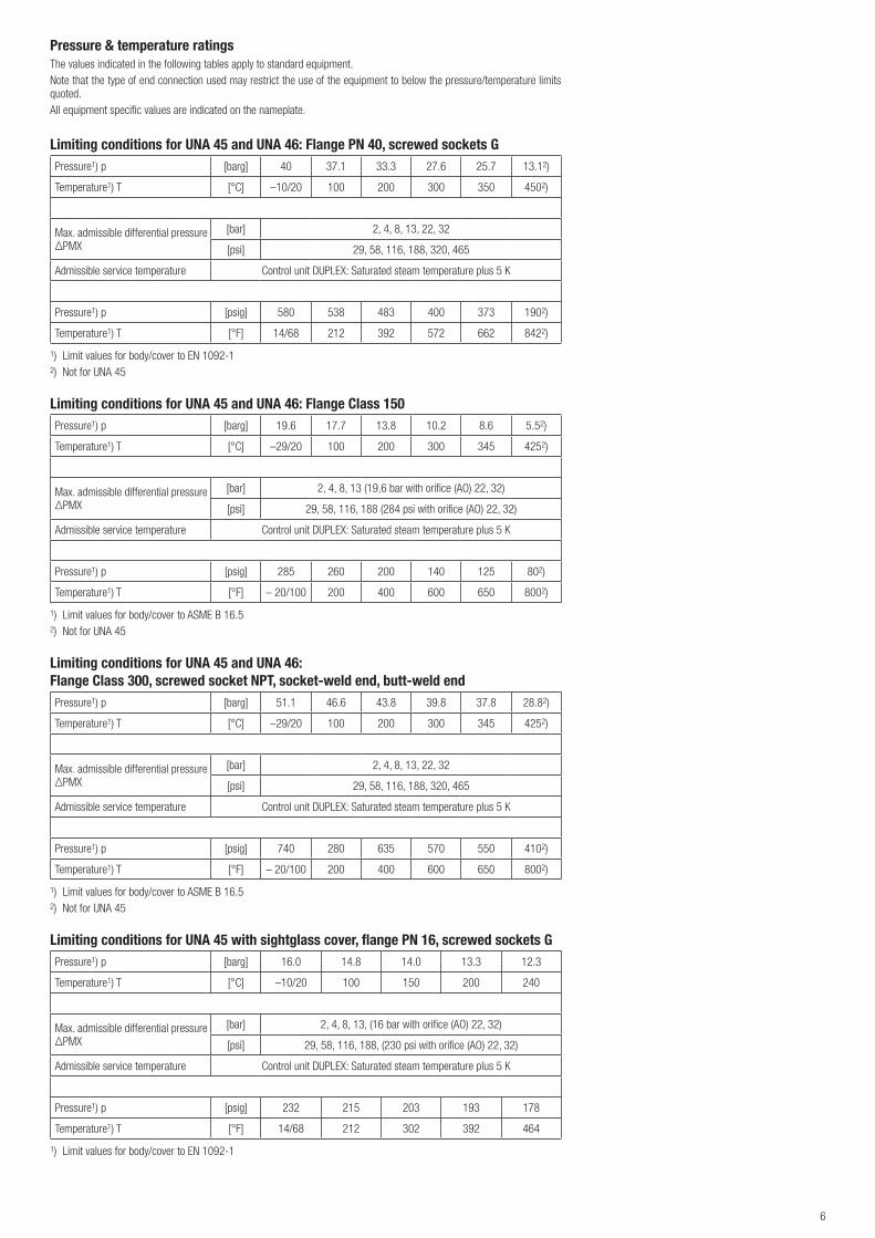
Pressure & temperature ratingsThe values indicated in the following tables apply to standard equipment.Note that the type of end connection used may restrict the use of the equipment to below the pressure/temperature limits quoted.All equipment specific values are indicated on the nameplate.
Limiting conditions for UNA 45 and UNA 46: Flange PN 40, screwed sockets GPressure1) p [barg] 40 37.1 33.3 27.6 25.7 13.12)
Temperature1) T [°C] –10/20 100 200 300 350 4502)
Max. admissible differential pressureΔPMX
[bar] 2, 4, 8, 13, 22, 32
[psi] 29, 58, 116, 188, 320, 465
Admissible service temperature Control unit DUPLEX: Saturated steam temperature plus 5 K
Pressure1) p [psig] 580 538 483 400 373 1902)
Temperature1) T [°F] 14/68 212 392 572 662 8422)
1) Limit values for body/cover to EN 1092-12) Not for UNA 45
Limiting conditions for UNA 45 and UNA 46: Flange Class 150Pressure1) p [barg] 19.6 17.7 13.8 10.2 8.6 5.52)
Temperature1) T [°C] –29/20 100 200 300 345 4252)
Max. admissible differential pressureΔPMX
[bar] 2, 4, 8, 13 (19,6 bar with orifice (AO) 22, 32)
[psi] 29, 58, 116, 188 (284 psi with orifice (AO) 22, 32)
Admissible service temperature Control unit DUPLEX: Saturated steam temperature plus 5 K
Pressure1) p [psig] 285 260 200 140 125 802)
Temperature1) T [°F] – 20/100 200 400 600 650 8002)
1) Limit values for body/cover to ASME B 16.52) Not for UNA 45
Limiting conditions for UNA 45 and UNA 46:Flange Class 300, screwed socket NPT, socket-weld end, butt-weld endPressure1) p [barg] 51.1 46.6 43.8 39.8 37.8 28.82)
Temperature1) T [°C] –29/20 100 200 300 345 4252)
Max. admissible differential pressureΔPMX
[bar] 2, 4, 8, 13, 22, 32
[psi] 29, 58, 116, 188, 320, 465
Admissible service temperature Control unit DUPLEX: Saturated steam temperature plus 5 K
Pressure1) p [psig] 740 280 635 570 550 4102)
Temperature1) T [°F] – 20/100 200 400 600 650 8002)
1) Limit values for body/cover to ASME B 16.52) Not for UNA 45
Limiting conditions for UNA 45 with sightglass cover, flange PN 16, screwed sockets GPressure1) p [barg] 16.0 14.8 14.0 13.3 12.3
Temperature1) T [°C] –10/20 100 150 200 240
Max. admissible differential pressureΔPMX
[bar] 2, 4, 8, 13, (16 bar with orifice (AO) 22, 32)
[psi] 29, 58, 116, 188, (230 psi with orifice (AO) 22, 32)
Admissible service temperature Control unit DUPLEX: Saturated steam temperature plus 5 K
Pressure1) p [psig] 232 215 203 193 178
Temperature1) T [°F] 14/68 212 302 392 464
1) Limit values for body/cover to EN 1092-1
7
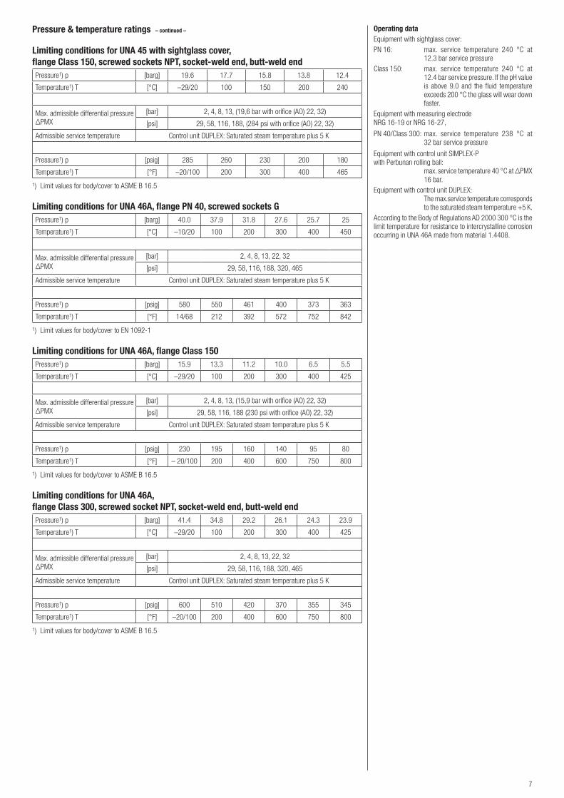
Pressure & temperature ratings – continued –
Limiting conditions for UNA 45 with sightglass cover,flange Class 150, screwed sockets NPT, socket-weld end, butt-weld endPressure1) p [barg] 19.6 17.7 15.8 13.8 12.4
Temperature1) T [°C] –29/20 100 150 200 240
Max. admissible differential pressureΔPMX
[bar] 2, 4, 8, 13, (19,6 bar with orifice (AO) 22, 32)
[psi] 29, 58, 116, 188, (284 psi with orifice (AO) 22, 32)
Admissible service temperature Control unit DUPLEX: Saturated steam temperature plus 5 K
Pressure1) p [psig] 285 260 230 200 180
Temperature1) T [°F] –20/100 200 300 400 465
1) Limit values for body/cover to ASME B 16.5
Limiting conditions for UNA 46A, flange PN 40, screwed sockets GPressure1) p [barg] 40.0 37.9 31.8 27.6 25.7 25
Temperature1) T [°C] –10/20 100 200 300 400 450
Max. admissible differential pressureΔPMX
[bar] 2, 4, 8, 13, 22, 32
[psi] 29, 58, 116, 188, 320, 465
Admissible service temperature Control unit DUPLEX: Saturated steam temperature plus 5 K
Pressure1) p [psig] 580 550 461 400 373 363
Temperature1) T [°F] 14/68 212 392 572 752 842
1) Limit values for body/cover to EN 1092-1
Limiting conditions for UNA 46A, flange Class 150Pressure1) p [barg] 15.9 13.3 11.2 10.0 6.5 5.5
Temperature1) T [°C] –29/20 100 200 300 400 425
Max. admissible differential pressureΔPMX
[bar] 2, 4, 8, 13, (15,9 bar with orifice (AO) 22, 32)
[psi] 29, 58, 116, 188 (230 psi with orifice (AO) 22, 32)
Admissible service temperature Control unit DUPLEX: Saturated steam temperature plus 5 K
Pressure1) p [psig] 230 195 160 140 95 80
Temperature1) T [°F] – 20/100 200 400 600 750 800
1) Limit values for body/cover to ASME B 16.5
Limiting conditions for UNA 46A,flange Class 300, screwed socket NPT, socket-weld end, butt-weld endPressure1) p [barg] 41.4 34.8 29.2 26.1 24.3 23.9
Temperature1) T [°C] –29/20 100 200 300 400 425
Max. admissible differential pressureΔPMX
[bar] 2, 4, 8, 13, 22, 32
[psi] 29, 58, 116, 188, 320, 465
Admissible service temperature Control unit DUPLEX: Saturated steam temperature plus 5 K
Pressure1) p [psig] 600 510 420 370 355 345
Temperature1) T [°F] –20/100 200 400 600 750 800
1) Limit values for body/cover to ASME B 16.5
Operating dataEquipment with sightglass cover:PN 16: max. service temperature 240 °C at 12.3 bar service pressureClass 150: max. service temperature 240 °C at 12.4 bar service pressure. If the pH value is above 9.0 and the fluid temperature exceeds 200 °C the glass will wear down faster.Equipment with measuring electrode NRG 16-19 or NRG 16-27,
PN 40/Class 300: max. service temperature 238 °C at 32 bar service pressure
Equipment with control unit SIMPLEX-P with Perbunan rolling ball: max. service temperature 40 °C at ΔPMX 16 bar.Equipment with control unit DUPLEX: The max.service temperature corresponds to the saturated steam temperature +5 K.According to the Body of Regulations AD 2000 300 °C is the limit temperature for resistance to intercrystalline corrosion occurring in UNA 46A made from material 1.4408.

8
Capacity ChartThe chart shows the maximum capacities for hot condensate for the various orifices.The capacities are dependent on the differential pressure (working pressure). The differential pressure is the difference between inlet and outlet pressure and depends among other things on the run of the condensate line. If the condensate downstream of the trap is lifted, the differential pressure is reduced by approximately 1 bar for 7 m lift.The max. admissible differential pressure is a function of the cross-sectional area of the orifice and the density of the fluid to be discharged.The graphs in the chart show the hot water flowrates that the steam traps UNA 45, UNA 46 and UNA 46A can discharge with virtually no banking up.The cold water capacities of steam traps with control unit SIMPLEX / DUPLEX are: Capacity multiplied by factor F.
Capacity Chart
DN 40-65 - AO 2
DN 40-65 - AO 4
DN 40-65 - AO 8
DN 40-65 - AO 13
DN 40-65 - AO 22
DN 40-65 - AO 32
DN 15-25 - AO 2
DN 15-25 - AO 4
DN 15-25 - AO 8
DN 15-25 - AO 13
DN 15-25 - AO 22
DN 15-25 - AO 32
100,1 200,2 0,3 0,4 0,60,8 3254321 86[bar]
[psi]46520 30010 1006 608 803 304 40 20021,5
100
4000
5000
6000
3000
2000
1000
7000
600
800
400
500
300
200
[kg/h][lb/h]
4000
3000
2000
1000
6000
8000
600
400
800
300
200
10000
15000
DifferenzdruckDifferential pressure
Cap
acity
Dur
chflu
ss
The max. differential pressure Δ PMX of the equipment depends on the type of orifice (AO) used.
Orifice ΔPMX [bar]Diameter of bore [mm]
DN 15-25 DN 40-65
2 2 8 15.0
4 4 6 12.5
8 8 4.8 10.0
13 13 4.1 8.5
22 22 3.5 7.0
32 32 3.0 6.5
0,1 0,2 0,3 0,4 0,6 0,8 21 3 4 6 8 10 20
[bar]
32
100
200
300
400
600
800
1000
2000
3000
4000
[kg/h]
7000
6000
5000
500
DN 15-25 - AO 32DN 15-25 - AO 22DN 15-25 - AO 13
DN 15-25 - AO 8DN 15-25 - AO 4
DN 15-25 - AO 2
DN 40-50 - AO 32DN 40-50 - AO 22DN 40-50 - AO 13
DN 40-50 - AO 8DN 40-50 - AO 4DN 40-50 - AO 2
[psi]
2 3 4 6 8 10 20 30 40 60 80 100 200 4651,5
200
300
400
600
800
1000
2000
3000
4000
6000
8000
10000
[lb/h]
500
Factor F = 1 1.1 1.18 1.2 1.3 1.4 1.48 1.53
9
3 4
28 18 19 20
2713 31
16
12
32
Inspection & CertificationDocumentation regarding material tests and in-house examination with test report to EN 10204 available at extra cost. All inspection requirements have to be stated with the enquiry or order. After supply of the equipment certification cannot be established. Charges and extent of the above mentioned test certificates as well as the different tests confirmed therein are listed in our Price List “Test and In-spection Charges for Standard Equipment”. For other tests and inspections please consult us.
Pressure Equipment DirectiveThe equipment fulfills the requirements of the Pressure Equipment Directive PED 97/23/EC and can be used for the following fluids:
UNA 45Fluids of group 2
UNA 46 und UNA 46AFluids of group 1Fluids of group 2
The equipment has a CE marking on the name plate.
The following types of equipment are excluded from the scope of the PED according to Article 3.3 and must not bear a CE marking.
Equipment with DN 15 up to DN 25
Equipment with PN 16 or Class 150 and DN 40 or DN 50
ATEXThe equipment does not have its own potential source of ignition and is therefore not subject to the ATEX Directive 94/9/EC.
The equipment is not Ex marked.
Please observe the following notes if the equipment is to be used in explosion-risk areas:
The equipment can be used in zones (surrounding atmosphere acc. to Directive 1999/92/EC) 0, 1, 2, 20, 21 and 22 (ATEX Directive 94/9/EC).
Make sure that the operating fluid does not generate a surface temperature that exceeds the limit specified for the place of installation.
If the equipment is electrically insulated when installed between pipe end connections, appropriate measures must be taken to discharge any static electricity.
819345-00/08-2014cm (808923-00) · GESTRA AG · Bremen · Printed in Germany
Supply in accordance with our general terms of business.
Ball Float Steam TrapUNA 45, UNA 46, UNA 46ADN 15, 20, 25, 40, 50, 65PN 40/Class 300
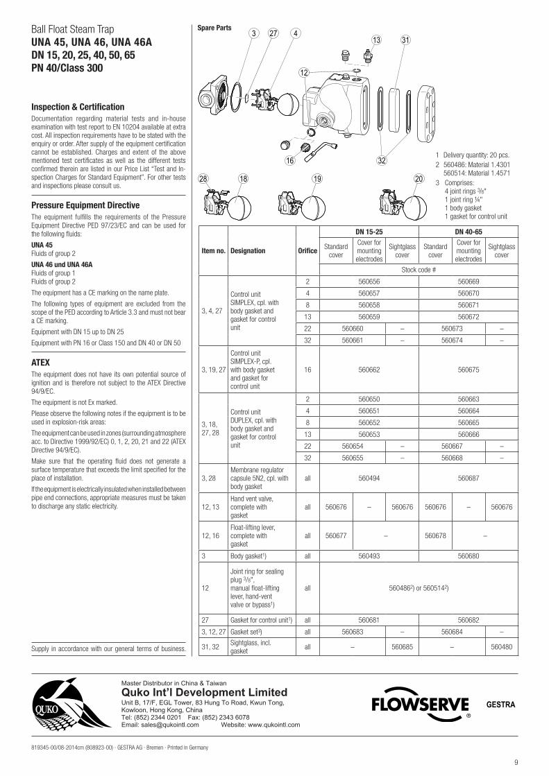
Spare Parts
Item no. Designation Orifice
DN 15-25 DN 40-65
Standardcover
Cover formountingelectrodes
Sightglasscover
Standardcover
Cover formountingelectrodes
Sightglasscover
Stock code #
3, 4, 27
Control unitSIMPLEX, cpl. withbody gasket andgasket for controlunit
2 560656 560669
4 560657 560670
8 560658 560671
13 560659 560672
22 560660 – 560673 –
32 560661 – 560674 –
3, 19, 27
Control unitSIMPLEX-P, cpl.with body gasketand gasket forcontrol unit
16 560662 560675
3, 18,27, 28
Control unit DUPLEX, cpl. withbody gasket andgasket for controlunit
2 560650 560663
4 560651 560664
8 560652 560665
13 560653 560666
22 560654 – 560667 –
32 560655 – 560668 –
3, 28Membrane regulator capsule 5N2, cpl. with body gasket
all 560494 560687
12, 13Hand vent valve,complete withgasket
all 560676 – 560676 560676 – 560676
12, 16Float-lifting lever,complete withgasket
all 560677 – 560678 –
3 Body gasket1) all 560493 560680
12
Joint ring for sealing plug 3/8", manual float-liftinglever, hand-ventvalve or bypass1)
all 5604862) or 5605142)
27 Gasket for control unit1) all 560681 560682
3, 12, 27 Gasket set3) all 560683 – 560684 –
31, 32 Sightglass, incl.gasket all – 560685 – 560480
1 Delivery quantity: 20 pcs.2 560486: Material 1.4301
560514: Material 1.45713 Comprises:
4 joint rings 3/8" 1 joint ring ¼" 1 body gasket
1 gasket for control unit
Master Distributor in China & TaiwanQuko Int’l Development LimitedUnit B, 17/F, EGL Tower, 83 Hung To Road, Kwun Tong,Kowloon, Hong Kong, ChinaTel: (852) 2344 0201 Fax: (852) 2343 6078Email: [email protected] Website: www.qukointl.com
GESTRA


