

Operation Manual
“Basic Hydraulic Components Kit” Training System
RE 09960-B/04.08


Operation Manual Basic Hydraulic Components Kit | RE 09960 Bosch Rexroth AG 3/36
Notes
Table of Contents 1 About this Manual.......................................................................................... 4
Related Documentation ................................................................................... 4 2 Principal Safety Instructions........................................................................... 5
Intended Use ................................................................................................... 5 Non-Intended Use ........................................................................................... 5 Qualification of Staff......................................................................................... 5 Warning Notices in this Manual ....................................................................... 7 You have to Observe the Following................................................................. 7 Obligations of the Operator............................................................................ 10 Safety Devices............................................................................................... 10 Training Stations............................................................................................ 11
3 Scope of Delivery ........................................................................................ 12 4 Product Description ..................................................................................... 13
Specification .................................................................................................. 13 Device Description......................................................................................... 14 Operating and Display Elements ................................................................... 15 Drive module ................................................................................................. 15 Identification of the Product ........................................................................... 17
5 Transport and Storage................................................................................. 18 6 Assembly..................................................................................................... 19
Mounting the Frame ...................................................................................... 20 Assembly of Hydraulic Components .............................................................. 21
7 Commissioning ............................................................................................ 24 Initial Commissioning..................................................................................... 24
8 Operation .................................................................................................... 26 9 Maintenance and Servicing.......................................................................... 27
Cleaning and Maintenance ............................................................................ 27 Maintenance Schedule .................................................................................. 28 Maintenance .................................................................................................. 29
10 Decommissioning ........................................................................................ 31 11 Disassembly and Replacement.................................................................... 31 12 Disposal ...................................................................................................... 31
Environmental Protection............................................................................... 31 13 Fault Finding and Troubleshooting............................................................... 32 14 Extension and Transformation ..................................................................... 32 15 Technical Data............................................................................................. 33 16 Index ........................................................................................................... 33
4/36 Bosch Rexroth AG Operation Manual Basic Hydraulic Components Kit | RE 09960
Notes
1 About this Manual This manual contains important information for the safe and appropriate transport, installation, commissioning, operation, maintenance, disassembly, and independent troubleshooting of simple malfunctions of the basic hydraulic components kit.
Please read this manual thoroughly, particularly the chapter on “Principal Safety Instructions” on page Fehler! Textmarke nicht definiert., before working with the basic hydraulic components kit.
Related Documentation Please also observe the following manuals: Data sheet RE 51142 “Clamping and Drive Module, type UPE2”. Data sheet RE 07008 “General Product Information for Hydraulic Products”.
Please also observe the generally valid legal and other relevant provisions of the European and/or national legislation as well as the provisions on the prevention of accidents and on environmental protection valid in your country.
The data specifed above only serve to describe the product. No statements concerning a certain condition or suitability for a certain application can be derived from our information. The information given does not release the user from the obligation of own judgment and verification. It must be rememebered that our products are subject to a natural process of wear and aging.
© This document, as well as the data, specifications and other information set forth in it, are the exclusive property of Bosch Rexroth AG. It may not be reproduced or given to third parties without its consent.
Subjet to revision. Printed in Germany.
RE 09960-B/04.08
Mat. - Nr. R961004689

Operation Manual Basic Hydraulic Components Kit | RE 09960 Bosch Rexroth AG 5/36
Notes
2 Principal Safety Instructions The basic hydraulic components kit was manufactured according to the state of the art. Nevertheless, there is a risk of personal injury and damage to property if you do not comply with the following principal safety instructions and the warning notices indicated before the instructions given in this manual.
Read this manual carefully and completely, before working with the basic hydraulic components kit.
Keep the manual at hand for future reference by any user. Hand over the basic hydraulic components kit to third parties only together
with this manual.
Intended Use The basic hydraulic components kit is a product complying with the Machinery Directive 98/37/EC (entire machine).
Observe the specification limits indicated in the technical data.
The basic hydraulic components kit must only be used in order to convey hydraulic skills and knowledge in the framework of commercial technical education and further education. For the development of control circuits and simulations, only devices and device kits approved for the basic hydraulic components kit must be used. The basic hydraulic components kit is a technical working appliance and not intended for any private use. The intended use is also based upon the provision that you have completely read and understood this manual, particularly chapter 2 “Principal Safety Instructions”.
Non-Intended Use The basic hydraulic components kit must never be used with actuators and components other than those provided in the framework of the basic hydraulic components kit. The drive module must not be used for continuous duty. After an operation of 15 minutes at most, it must be switched off and not be used for 30 minutes. Non-intended use is any use of the basic hydraulic components kit other than the use described in chapter “Intended use”. The connection of several pressurized circuits is forbidden. It is also prohibited to use the training system, both during the technical exercises and out of lessons, for amateurish or unprofessional purposes.
Qualification of Staff
Training Lessons
Trainees and apprentices may work on the basic hydraulic components only under direct supervision and in accordance with the instructions of the trainer or qualified staff.
Trainer The trainer for the training system must be a skilled and qualified expert having experience with electric, hydraulic and mechanical systems, as well as in the mechatronics field. The trainer must

6/36 Bosch Rexroth AG Operation Manual Basic Hydraulic Components Kit | RE 09960
Notes
give clear instructions, when trainees or participants in training courses are to install control circuits on the “Basic Hydraulic Components Kit” training system.
check the installation and functional consequences of the control circuits, before they are switched on, in order to ensure a safe operation.
answer any questions in a clear and easy-to-understand way.
Qualified staff Qualified staff can also be deployed for the monitoring of trainees during exercises on the “Basic Hydraulic Component Kit” training system. This includes qualified persons who were instructed and informed about: assigned tasks, possible risks in case of inappropriate use, safety devices and protective measures.
Transport, Installation, Assembly and Commissioning
Any installation, connection, maintenance, or repair works on the “Basic Hydraulic Components Kit” training system must only be carried out by authorized and skilled experts or by any person having sufficient qualification or authorization. People entrusted with works to be carried out on the “Basic Hydraulic Component Kit” training system must be able to understand the instructions given in this documentation as well as to also carry out any missing instructions on the basis of their own professional qualification.
Troubleshooting, Maintenance and Repair Maintenance and repair works as well as fault finding and troubleshooting measures require special knowledge and must only be carried out by qualified experts! Works on electrical equipment must only be carried out by a qualified electrician or by any other instructed person under the direction and supervision of a qualified electrician according to electrical regulations.
Qualified electrician A qualified electrician is any person who, due to their professional training, their skills and their experience as well as their knowledge of the relevant provisions, can assess the works assigned to them, recognize possible dangers and take suitable safety measures.
The data specifed above only serve to describe the product. No
not release the user from the obligation of own
statements concerning a certain condition or suitability for a certain application can be derived from our information. The information given does
Works on hydraulic components must only be carried out by skilled staff with special knowledge and experiences in the hydraulic field!
Hydraulic expert Special knowledge in the hydraulic field means that the staff must be able to read and completely understand hydraulic diagrams, particularly completely understand the interplay of the integrated safety devices, and have knowledge about the functionality and structure of hydraulic components.
judgment and verification. It must be rememebered that our products are subject to a natural process of wear and aging.
© This document, as well as the data, specifications and other information set forth in it, are the exclusive property of Bosch Rexroth AG. It may not be reproduced or given to third parties without its consent.
Subjet to revision. Printed in Germany.
RE 09960-B/04.08
Mat. - Nr. R961004689

Operation Manual Basic Hydraulic Components Kit | RE 09960 Bosch Rexroth AG 7/36
Notes
Warning Notices in this Manual In this manual, warning notices are given before an instruction, where there is a risk of personal injury or damage to property. The measures described for the prevention of risks have to be complied with. Warning notices are structured as follows:
SIGNAL WORD!
Type of danger! Consequences
Prevention measure
Warning sign (warning triangle): draws attention to the danger Signal word: indicates the severity of the danger Type of danger: indicates the type or source of the danger Consequences: describes the consequences in case of non-compliance Prevention measure: indicates how the danger can be avoided
The signal words have the following meaning: Table 1: Meaning of signal words
Signal word Application
DANGER!
marks an immediately threatening great danger which will surely cause severe injuries or even death if the danger is not prevented.
WARNING!
marks a possible danger which might cause severe injuries or even death if the danger is not prevented.
CAUTION!
points out to a possibly dangerous situation which could cause moderate or minor personal injuries or damage to material if it is not prevented.
If this information is not observed, this may lead to deteriorations in the operating sequence.
You have to Observe the Following
General Notices Observe the provisions on accident prevention and environmental protection valid in the country of the user and at the workplace.
Only use Rexroth products when they are in technically perfect condition. Check the product for evident faults, such as cracks in the housing or missing
lead seals, screws, caps or seals. Never modify or reconstruct the basic hydraulic components kit. Only use the product within the specifications indicated in the technical data.

8/36 Bosch Rexroth AG Operation Manual Basic Hydraulic Components Kit | RE 09960
Notes
Persons who install, operate, disassemble, or maintain Rexroth products must not be under the influence of alcohol, other drugs or medications that could affect their ability to react.
Make sure that all the safety devices belonging to the product are available, properly installed and fully functional. You must not modify the position of safety devices, avoid them or make them ineffective.
If it is necessary, e.g. for commissioning or maintenance works, that you switch off safety devices, you have to take measures guaranteeing that no dangerous situations may arise for persons or property. Always consult the superior operation manual of the machine or system in such case.
Never remove or damage lead seals attached by Bosch Rexroth. The warranty only applies to the supplied configuration. In case of incorrect installation, non-intended use and/or improper handling, the warranty expires.
Never load the product mechanically in an inadmissible way. Never use the product as a handle or step. Do not place any objects on the product.
Never switch on the system with uncoupled hoses. Immediately replace defective couplings. Faults occur on the O-ring seals. Do not close used Minimess connections with protecting caps. Contaminations may lead to coupling leakage.
Never try to close coupling connections using force; always relieve the pressure control valve. The connection can then be closed without any difficulties.
Never depressurize the hydraulic system by opening it (screwed connections).
During transport Please note that the grid, the drive module and the hydraulic components must be transported separately.
During assembly
Always depressurize and de-energize the relevant part of the system prior to installation and/or prior to connecting or pulling a plug.
The data specifed above only
application can be derived from
serve to describe the product. Nostatements concerning a certain condition or suitability for a certain
Prior to commissioning, make sure that all seals and caps of the plug connections are built in correctly and undamaged, in order to avoid that fluids or foreign bodies can penetrate into the product.
During assembly, make sure everything is clean in order to prevent dirt from penetrating into the hydraulic tubes and thus leading to wear and malfunctions of the product.
our information. The information given does not release the user from the obligation of own
Space requirement
judgment and verification. It must be rememebered that our products are subject to a natural process of wear and aging.
© This document, as well as the data, specifications and other information set forth in it, are the exclusive property of Bosch Rexroth AG. It may not be reproduced or given to third parties without its consent.
Subjet to revision. Printed in Germany.
RE 09960-B/04.08
M
In order to be able to teach and learn on the training system how processes work, the following space requirements are to be provided for the “Basic Hydraulic Components Kit” training system:
at. - Nr. R961004689

Operation Manual Basic Hydraulic Components Kit | RE 09960 Bosch Rexroth AG 9/36
Notes
Fig. 1: Space requirement for the hydraulic basics components kit
Installation surface The table or surface, where the “Basic Hydraulic Components Kit” training system is to be installed, must meet the following requirements: The load capacity of the table (the installation surface) must amount to at least 75 kg.
The installation surface must be at least 150 cm long and at least 75 cm large. The installation surface must be plane.
In order to guarantee an ergonomically favorable position for the operation of the training system, the table height has to comply with the following instructions: Work station (sitting): table height of 70-75 cm Work station (standing): table height of 90 cm
During operation
Trainees and apprentices must only work on the training system under supervision of trainers and skilled staff.
Restrict the access to the direct operating area of the system to persons authorized by the operator. This is also valid, when the system is at standstill.
In case of an emergency, an error or other irregularities, switch off the system and secure it against restarting.
During cleaning
Close all openings with the help of appropriate safety devices in order to prevent the cleaning agent from penetrating into the system.
Never use solvents or aggressive cleaning agents. Clean the product with a slightly humid non-fiber cloth. Use only water and, if need be, a mild cleaning agent for this.
Do not use pressure washers to clean the system.

10/36 Bosch Rexroth AG Operation Manual Basic Hydraulic Components Kit | RE 09960
Notes
During maintenance and servicing Carry out the maintenance works prescribed at the intervals stipulated in the operation manual.
Make sure that the hose lines, connections and components are not loosened as long as the system is under pressure and voltage. Secure the system against restarting.
During disposal Dispose of the product in accordance with the provisions valid in your country. Dispose of the hydraulic fluid in accordance with the provisions valid in your country.
Dispose of any hydraulic fluid residues according to the respectively valid safety data sheets for hydraulic fluids.
Obligations of the Operator The operator must make sure that the requirements for the installation and assembly of the basic hydraulic components kit are met and - ensure a safe installation of the training system by the staff and/or by persons
authorized by the operator. - instruct their employees and/or employees of third companies about possible
risks on the site of installation. - make sure that accident prevention regulations, safety instructions of the
professional associations as well as further in-house, local stipulations are complied with.
The operator must provide sufficient lighting in the installation area of the training system.
The operator of the “Basic Hydraulic Components Kit” training system must instruct their staff at regular intervals regarding the following subjects: - observation and compliance with the operating manual as well as legal
provisions - intended use of the basic hydraulic components kit
The data specifed above only serve to describe the product. No
tements concerning a certain tion or suitability for a certain
tion can be derived from our information. The information given does not release the user from the obligation of own
- compliance with instructions of the works protection force and the operating instructions of the operator
- behavior in an emergency stacondi applica
Bosch Rexroth offers additional training courses in special technical fields. An overview of the course contents is given in the internet under http://www.boschrexroth.de/didactic.
judgment and verification. It must be rememebered that our products
ct to a natural process of wear and aging.
This document, a a data, specificationinformation set forth in it, are the exclusive property of Bosch
G. It may not be ced or given to third
s without its consent.
Subjet to revision. in Germany.
RE 09960-B/04.08
M
Safety Devices are subjeIn order to protect the operating staff, the training system is equipped with the
following safety devices: © s well s the
s and other hydraulic pressure limitation of the hydraulic unit with the help of the pressure control valve
protective sheathing of the cylinder Rexroth Areprodupartie
Hydraulic pressure limitation
Printed
The training system must only be operated up to a maximum hydraulic operating pressure of 50 bars. The pressure is limited to 50 bars by means of a pressure control valve. It is not possible to set a higher pressure on the pressure control valve.
Protective sheathing of the cylinder The stroke area of the cylinder is equipped with a fixed protective cap made of transparent polymethyl methacrylate.
at. - Nr. R961004689

Operation Manual Basic Hydraulic Components Kit | RE 09960 Bosch Rexroth AG 11/36
Notes
Personal protective equipment The operator must provide personal protective equipment (such as e.g. gloves, safety boots, protective glasses, overalls etc.).
Training Stations Subject to the use of the basic hydraulic components kit, the following training stations are provided: Table 2: Training stations on the basic hydraulic components kit
Work step Number of persons Configuration 2 Operation 2

12/36 Bosch Rexroth AG Operation Manual Basic Hydraulic Components Kit | RE 09960
Notes
3 Scope of Delivery The following is included in the scope of delivery: operation manual for the basic hydraulic components kit frame including grid 1,000x500x30
- pre-assembled: frame parts connected via two joints - 2 cross members
Fig. 2: Scope of delivery of the frame
hydraulic components - party pre-assembled
The data specifed above only serve to describe the product. No statements concerning a certain condition or suitability for a certain application can be derived from our information. The information given does not release the user from the obligation of own judgment and verification. It must be rememebered that our products are subject to a natural process of wear and aging.
© This document, as well as the Fig. 3: Scope of delivery of hydraulic components data, specifications and other
Rexroth AG. It may not be roduced or given to third
Subjet to revision. Printed in Germany.
RE 09960-B/04.08
M
information set forth in it, are the exclusive property of Bosch
repparties without its consent.
at. - Nr. R961004689
1 Cylinder with measuring ports, throttle valve and hose lines
2 Drive module with operating unit 3 Pressure gauge to be hung up on
the grid 4 Directional control valve with
throttle valve and hose lines
5 pressure-reducing valve with hose lines
6 hose line 7 2 screw-in pressure gauges

Operation Manual Basic Hydraulic Components Kit | RE 09960 Bosch Rexroth AG 13/36
Notes
4 Product Description
Specification The basic hydraulic components kit is a components pack for beginners. It allows conveying the following contents in the framework of industrial education and further education: identification of components commissioning how does pressure develop? directional control valve, direction of travel of the cylinder load pressure setting the velocity, inlet throttle change of pressure difference via the system pressure change of pressure difference via the load pressure pressure transmission, outlet throttle pressure reduction, force-distance curve

14/36 Bosch Rexroth AG Operation Manual Basic Hydraulic Components Kit | RE 09960
Notes
Device Description The basic hydraulic components kit comprises the following components:
Fig. 4: Individual components of the basic hydraulic components kit
The data specifed above only serve to describe the product. No statements concerning a certain condition or suitability for a certain application can be derived from
rmation given does not release the user
n
1 Drive module 2 Electric control unit with main
switch 3 Manual directional control valve
with throttle valve 4 Pressure-reducing valve
5 200 cm cylinder with throttle valve 6 Pressure gauge 7 Frame with grid 8 Pressure gauge
Frame with grid Pressure gauges The pressure gauges display the pressure in bars.
our information. The info
from the obligation of owjudgment and verification
On the frame with grid, the individual components of the basic hydraulic components kit are fixed.
Electric control unit with main switch Drive module . It m
be rememebered that our produst ucts
are subject to a natural process of
t, as well as the
Subjet to revision. Printed in Germany.
RE 09960-B/04.08
M
The drive module serves to feed hydraulic fluid into the hydraulic circuit.
wear and aging.
© This documen
The drive module is switched on and off, respectively, by means of the main switch.
Manual directional control valve
data, specifications and other information set forth in it, are the
The 4-port directional control valve with 3 outputs releases different groups of lines. It is operated manually and reset by means of spring force.
Pressure-reducing valve
exclusive property of Bosch Rexroth AG. It may not be
With the help of the pressure-reducing valve, the pressure on working port A is set.
200 cm cylinder Throttle valves The throttle valves serve to set the volumetric flow in the inlet lines of the cylinder.
reproduced or given to third parties without its consent.
Tension-rod type cylinder with one port each on the piston and the rod side. For reasons of protection, the cylinder is equipped with a protective sheathing.
at. - Nr. R961004689
Operation Manual Basic Hydraulic Components Kit | RE 09960 Bosch Rexroth AG 15/36
Notes
Operating and Display Elements
Drive module
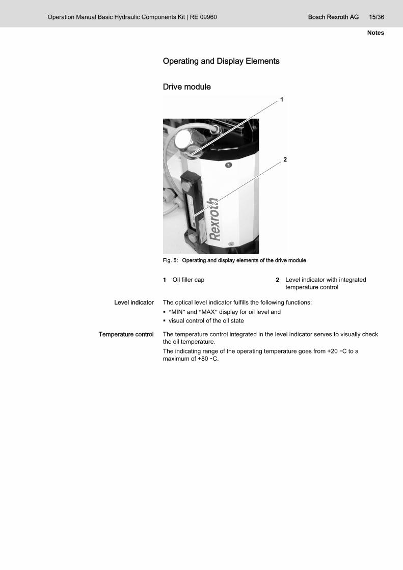
Fig. 5: Operating and display elements of the drive module
1 Oil filler cap 2 Level indicator with integrated temperature control
Level indicator The optical level indicator fulfills the following functions: “MIN” and “MAX” display for oil level and visual control of the oil state
Temperature control The temperature control integrated in the level indicator serves to visually check the oil temperature. The indicating range of the operating temperature goes from +20 ーC to a maximum of +80 ーC.

16/36 Bosch Rexroth AG Operation Manual Basic Hydraulic Components Kit | RE 09960
Notes
Hydraulic components
Fig. 6: Operating and display elements for hydraulic components
1 Pressure gauge 2 Main switch 3 Handle-operated lever for
directional control valve
4 Pressure gauge 5 Adjusting screws for throttle valves
Main switch Pressure gauges The pressure gauges display the pressure in bars.
The data specifed above only serve to describe the product. No statements concerning a certain
rtain application can be derived from
he information lease the user
from the obligation of own
The drive module is switched on and off, respectively, by means of the main switch on the control unit.
Handle-operated lever for directional control valve
Adjusting screws for throttle valves
condition or suitability for a ce
our information. Tgiven does not re
The handle-operated lever on the directional control valve releases different groups of lines. The adjusting screws serve to manually relieve the throttle valves.
judgment and verification. It must be rememebered that our products are subject to a natural process of wear and aging.
© This document, as well as the data, specifications and other information set forth in it, are the exclusive property of Bosch Rexroth AG. It may not be reproduced or given to third parties without its consent.
Subjet to revision. Printed in Germany.
RE 09960-B/04.08
Mat. - Nr. R961004689

Operation Manual Basic Hydraulic Components Kit | RE 09960 Bosch Rexroth AG 17/36
Notes
Identification of the Product The name plate of the drive module for the “Basic Hydraulic Components Kit” training system is attached to the top side of the drive module.
Fig. 7: Name plate of drive module

18/36 Bosch Rexroth AG Operation Manual Basic Hydraulic Components Kit | RE 09960
Notes
5 Transport and Storage For the transport and storage of the kit, you must comply with the ambient conditions indicated in the technical data (see “Technical Data” on page 33). Please note that the grid, the drive module and the hydraulic components must be transported separately. The drive module must always be transported and stored vertically - i.e. with the handle pointing to the top.
The data specifed above only serve to describe the product. No statements concerning a certain condition or suitability for a certain application can be derived from our information. The information given does not release the user from the obligation of own judgment and verification. It must be rememebered that our products are subject to a natural process of wear and aging.
© This document, as well as the data, specifications and other information set forth in it, are the exclusive property of Bosch Rexroth AG. It may not be reproduced or given to third parties without its consent.
Subjet to revision. Printed in Germany.
RE 09960-B/04.08
Mat. - Nr. R961004689
Operation Manual Basic Hydraulic Components Kit | RE 09960 Bosch Rexroth AG 19/36
Notes
6 Assembly
CAUTION! Risk of personal injury and damage to property! Any irregularities, deviations, defaults, or vices may lead to personal injury or damage to products.
Examine the cause and repair the default. Replace the defective component. Do not put the basic hydraulic component kit into operation or switch off the
training system immediately.
Preparations for installation An impeccable installation is based upon the fact that:
all required components are within reach and operational, required auxiliary means, such as lifting gears, ladders and stepladders, barriers are provided.
Before the final installation, the following items have to be checked: Are the clearance required for the basic hydraulic components kit and the safety distances to other fixed installations complied with (for corresponding instructions, see page 9)?
Is the installation surface plane? Does the installation surface have the required load capacity? Is the installation surface sufficiently dimensioned? Is an electrical connection available? Are the light conditions at the site of installation sufficient?
Unpacking Dispose of the packaging in accordance with the provisions applicable in your country.
Installation conditions For the installation, you must comply with the ambient conditions indicated in the technical data (see “Technical Data” on page 33).
Required tools 5 mm Allen key

20/36 Bosch Rexroth AG Operation Manual Basic Hydraulic Components Kit | RE 09960
Notes
Mounting the Frame
Fig. 8: Arrange pre-assembled frame parts vertically
For the assembly of the frame, arrange the frames already connected via joints in a vertical manner.
The data specifed above only serve to describe the product. No statements concerning a certain condition or suitability for a certain application can be derived from our information. The information given does not release the user from the obligation of own judgment and verification. It must be rememebered that our products are subject to a natural process of wear and aging.
© This document, as well as the
Fig. 9: Cross member data, specifications and other information set forth in it, are the
ve property of Bosch Rexroth AG. It may not be
ced or given to third s without its consent.
M
exclusi
reprodupartie
1 Sliding blocks 2 Screws
1. Remove the covering caps from the frame's ends.
Subjet to revision. Printed in Germany.
RE 09960-B/04.08
2. Loosen the screws on both sides on the delivered cross members, until the sliding blocks can be slightly pulled out. The screws, however, should not be removed completely.
at. - Nr. R9610046893. Now, push the sliding blocks on both sides into the frame’s profile.

Operation Manual Basic Hydraulic Components Kit | RE 09960 Bosch Rexroth AG 21/36
Notes
4. Align the cross members at the height of the bottom cross member of the frame.
5. Tighten the loose screws on the cross members again. 6. Tighten the two screws on the upper joint. 7. Put the frame’s covering caps on the free frame's ends.
Turn the frame by 180°. Repeat steps 1 to 6 on the other side of the frame. Put the frame on the installation surface.
The frame is now completely mounted.
Assembly of Hydraulic Components
CAUTION! Risk of personal injury or damage to property! The installation of the product requires basic hydraulic knowledge.
The product must solely be assembled by qualified personnel (see “Qualification of Staff” on page Fehler! Textmarke nicht definiert.).
All hydraulic components - with the exception of the drive module and the screw-in pressure gauges - are hung up on the grid. The mounting unit is provided on the back side of the respective component.
Mounting on the grid
Fig. 10: Example of holder
For this, push at first the longer part of the mounting unit through the grid. Now, lift the mounting unit in order to also push the lower part of the mounting
unit behind the grid. Guide the component down, until it is safely mounted in the grid.

22/36 Bosch Rexroth AG Operation Manual Basic Hydraulic Components Kit | RE 09960
Notes
Fig. 11: Arrangement of hydraulic components
The data specifed above only serve to describe the product. No statements concerning a certain condition or suitability for a certain application can be derived from our information. The information given does not release the user from the obligation of own
1 Drive module 2 Electric control unit with main
switch 3 Manual directional control valve
with throttle valve 4 Pressure-reducing valve
5 200 cm cylinder with throttle valve 6 Pressure gauge on the piston side
of the cylinder 7 Pressure gauge on the piston side
of the cylinder 8 Pressure gauge to be hung up on
the grid
Put the frame on the work surface.
judgment and verification. It must be rememebered that our products are subject to a natural process of wear and aging.
© This document, as well as the data, specifications and other
ven to third
Subjet to revision.
RE 09960-B/04.08
M
Fig. 12: Holder of drive module
information set forth in it, are the exclusive property of Bosch
y not beRexroth AG. It mareproduced or gi
Fix the drive module by means of the holder screwed to the bottom right to the frame. Fix the two sliding blocks of the holder in the frame's profile.
Hang up the electric control unit at the right bottom of the grid. parties without its consent. Hang up the manual directional control valve with throttle valve, left to the
control unit, on the grid. Printed in Germany. Hang up the pressure-reducing valve, left to the directional control valve, on
the grid.
at. - Nr. R961004689

Operation Manual Basic Hydraulic Components Kit | RE 09960 Bosch Rexroth AG 23/36
Notes
Hang up the cylinder, above the directional control valve and pressure-reducing valve, on the grid.
Screw the pressure gauges to the measuring ports on the cylinder Hang up the pressure gauge, above the operating unit, on the grid.
The hydraulic components are now in the correct position.
24/36 Bosch Rexroth AG Operation Manual Basic Hydraulic Components Kit | RE 09960
Notes
7 Commissioning
Initial Commissioning Before the hydraulic unit can be switched on, the oil tank is to be filled. The basic hydraulic components kit is partially pre-assembled and only delivered, after tests have been carried out in the factory. During the transport, however, defaults or damage can occur on the training system. Before the hydraulic unit can be switched on, the oil tank is to be filled. Before the commissioning, always check the oil level, the minimum pressure setting, the electrical connection, the hose lines for damage, the hose couplings for tight fit, whether all components are undamaged, whether all attachment parts are correctly attached.
Inappropriate hydraulic fluids can lead to malfunctions and damage to the hydraulic installation. Do not use hydraulic fluid that is older than 1 year or that was stored outside. Aging products or condensate are possible.
Do not mix different hydraulic fluids. Even if they are of the same type, different hydraulic fluids have a different age and can - if mixed - lead to a deterioration of the hydraulic fluid.
Provide the specified hydraulic fluid in a sufficient quantity (see chapter Technical Data). Provide the specified hydraulic fluid in a sufficient quantity (see chapter Technical Data).
The data specifed above only ve to describe the product. No tements concerning a certain
condition or suitability for a certain application can be derived from our information. The information given does not release the user from the obligation of own
Requirements to be met for filling the oil tank: sersta The hydraulic unit is switched off and the power plug is not connected.
The hydraulic installation must be depressurized. Provide appropriate cleaning cloths.
How the hydraulic unit is filled:
Clean the environment of the filler. judgment and verification. It must d that our products
ct to a natural process of wear and aging.
© This document, as well as the data, specifications and other information set forth in it, are the exclusive property of Bosch
G. It may not be ced or given to third
s without its consent.
Subjet to revision. Printed in Germany.
RE 09960-B/04.08
M
be rememebereare subje Loosen the filler and breather cap and lay them aside.
Push the filter funnel into the oil filler.
Risk of injury! Slip hazard due to leaking hydraulic oil.
Rexroth Areprodu Immediately bind/dispose of leaking hydraulic fluid. partie Provide binding material before the filling or change of oil.
CAUTION!
Filling the oil tank
Checking the hydraulic feed
at. - Nr. R961004689
Operation Manual Basic Hydraulic Components Kit | RE 09960 Bosch Rexroth AG 25/36
Notes
Fill up hydraulic oil up to the “MAX” marking visible in the oil-level glass. Wait for about 15 minutes, until the hydraulic fluid settled down in the tank.
This is also valid, if you only refill partial quantities. Close the tank filler with the filler and breather cap. Remove any leaking hydraulic oil by means of the cleaning cloths. Always dispose of contaminated cleaning cloths according to the rules.
The oil tank is now refilled.
In order to confirm the actual oil level of the hydraulic unit, the hydraulic fluid must circulate in the system by means of the pump for about 20 minutes. During this, the oil is filtered through the optional line filter. After the time elapsed, the oil level is to be checked again and hydraulic oil is to be refilled, if necessary.
Switching on the power supply Connect the power plug to the socket (230 V). Switch the main switch provided on the operating module from “0” to “1”. Check the circuit after the first switch-on for leakages.

26/36 Bosch Rexroth AG Operation Manual Basic Hydraulic Components Kit | RE 09960
Notes
8 Operation If, during operation or inspection, any irregularities, deviations, defaults, or wear are noticed, you must in any case: immediately switch off the training system. examine the cause and remedy the default. replace the defective component. no longer put into operation the training system, if applicable.
All safety devices must be operational and complete. The unit must only be switched on, after the hose lines P and T were connected to the unit. Otherwise, there is a risk of quick heating of the unit and thus of damage to the pump. The unit was developed for the short-term duty cycle S3 only. After a duty time of 15 minutes at most, plan a resting period of about 30 minutes. After each exercise, the unit must be switched off.
Switching on
Prior to every switch-on, check the hydraulic fluid level. Before switching on the unit, check the hose and hose connections. Switch the main switch provided on the control unit from “0” to “1”.
Pressure relief Before and after each exercise, the unit must be depressurized. There are three possibilities to do this:
Depressurization on the pressure control valve
Depressurize the adjusting spindle by turning it completely to the left.
The connection P to T is depressurized.
Depressurization on the directional control valve The data spec
serve to descriifed above only be the product. No
statements concerning a certain itability for a certain
tion can be derived from ormation. The information
given does not release the user from the obligation of own
Pressure relief A to T: Operate the directional control valve manually in direction A.
condition or suapplicaour inf
Pressure relief B to T: Operate the directional control valve manually in direction B.
Depressurization on the pressure-reducing valve
Completely depressurize the pressure-reducing valve.
The connection A to T is depressurized. judgment and verification. It must be rememebered that our products are subject to a natural process of wear and aging.
© This document, as well as the data, specifications and other information set forth in it, are the exclusive property of Bosch Rexroth AG. It may not be reproduced or given to third parties without its consent.
Subjet to revision. Printed in Germany.
RE 09960-B/04.08
M
at. - Nr. R961004689

Operation Manual Basic Hydraulic Components Kit | RE 09960 Bosch Rexroth AG 27/36
Notes
9 Maintenance and Servicing Report any errors you detect to your superior in order for them to be repaired as quickly as possible. Note that small errors may turn into great errors, if they are not repaired in time. Clean plastic components only with a slightly humid cloth! Use only water and, if need be, a soft cleaning agent without chemical additives. Never use solvents or aggressive cleaning agents! Before using the cleaning agent, consult the operating instructions and the DIN material safety data sheet for its scope of application and possible risks. Never blow off dust from the training system with the help of compressed air, since this could damage sensors and valves of the function modules. If you have to remove oil, use appropriate binding materials and cleaning cloths! Protect the training system from dust and humidity so as to make sure that it does not contaminate and that you can use it for a long period of time.
Cleaning and Maintenance
When? Where? What? Remarks
Complete training system
Clean the environment of the training system. Clean and keep free work surfaces.
Remove any parts lying around. Immediately remove any fluid from the floor, bind it with an oil-binding agent and dispose of it.
Handles
Operating elements
Display and visual installations, sight glasses
Clean thoroughly. Before the beginning and after the end of the work, make sure the work surfaces and devices and device kits are clean!
Daily / before each use
Hydraulic components of the system and hose couplings
Clean contaminated parts. Immediately wipe up leaking oil with a cloth.
It is thus easier for you to detect and observe leakages.
Hydraulic lines and hydraulic hoses
Keep clean all lines, hoses and screwed connections. Check them for any leakage or externally visible damage!
If the exterior (abrasive points, cuts, breaks, embrittlements) is damaged, immediately replace the hydraulic hoses.
Hose couplings Check the free movement. Replace them immediately.
Hydraulic unit Check all lines, hoses and screwed connections for leakages or externally visible damage!
Check for leakages and visible damage. Immediately have repaired any damage
Complete training system
Check electrical connection cables and lines for visible damage (abrasive points, breaks, cuts).
Have repaired any damage immediately by the competent qualified electrician!
Weekly
Connecting elements Visual examination, check for damage and tight fit.
Tighten any loose screws etc. Immediately have repaired any damage!

28/36 Bosch Rexroth AG Operation Manual Basic Hydraulic Components Kit | RE 09960
Notes
Maintenance Schedule
The data specifed above only serve to describe the product. No statements concerning a certain condition or suitability for a certain
our information. The information given does not release the user from the obligation of own
application can be derived from
judgment and verification. It must be rememebered that our products are subject to a natural process of wear and aging.
© This document, as well as the data, specifications and other information set forth in it, are the exclusive property of Bosch Rexroth AG. It may not be reproduced or given to third parties without its consent.
Subjet to revision. Printed in Germany.
RE 09960-B/04.08
M
When? Where? What? Remarks
Oil tank
Check the level: above MIN? below MAX?
In case of low level: refill hydraulic fluid up to the MAX marking.
Fittings Check for externally visible damage! Breaks on pressure gauges?
Have them replaced immediately in case of damage! Inform Bosch Rexroth customer service.
Hydraulic unit Running smoothness of motor and pump: Noises? Vibrations?
Inform Bosch Rexroth customer service in case of irregularities.
Hydraulic lines, hydraulic hoses
Check all lines, hoses and screwed connections for leakages or externally visible damage!
Hydraulic hoses must be immediately replaced, if: the exterior is damaged (abrasive points, cuts, breaks, embrittlements). they are deformed in the pressurized or depressurized state, if the hydraulic hose lines do not have their natural forms. Leakages.
Hydraulic hoses Check the compliance with replacement delays.
Exchange / Replacement 6 years after date of manufacture at the latest.
Daily / before each use
Hydraulic fluid Check the compliance with replacement periods.
Exchange / Replacement, see manufacturer's specification.
Once every 10 operating hours
Pressurized circuit Switch the line filter to the circuit and filter the circulating oil for 15 minutes.
Any oil contaminations are removed / filtered out.
at. - Nr. R961004689

Operation Manual Basic Hydraulic Components Kit | RE 09960 Bosch Rexroth AG 29/36
Notes
Hydraulic wiring diagram with line filter
for oil cleaning
Maintenance Imperfect maintenance leads to faults and, as the case may be, to failure and high servicing costs. If, during operation or inspection, any irregularities, deviations, defaults or wear are noticed, you must in any case: immediately switch off the training system. examine the cause and remedy the default. replace the defective component. no longer put into operation the training system, if applicable.

30/36 Bosch Rexroth AG Operation Manual Basic Hydraulic Components Kit | RE 09960
Notes
WARNING! Risk of injury! Hydraulic oil squirting under high pressure can lead to very severe injuries!
Carry out any repair works only, when the basic hydraulic components kit is at standstill.
Before opening the unit, depressurize it. Despite the pressure relief, open the unit with the utmost care. Works on the hydraulic installation must only be carried out by a hydraulic
expert.
CAUTION! Risk of injury! Slip hazard due to leaking hydraulic oil.
Immediately bind/dispose of leaking hydraulic fluid. Provide binding material before the filling or change of oil.
DANGER! Risk of injury! Death or serious bodily injury due to dangerous electrical voltage!
Works on the electronic installation must only be carried out by a qualified electrician.
Replacement of parts Only use original equipment parts.
In case of replacement part orders, always indicate the device type and material number, the year of manufacture and the part designation. Please consult the Bosch Rexroth customer service. The “Address and Contact Data” are given on the verso of this operation manual. After the repair for wear and tear was carried out and before the unit can be put into operation again, a qualified expert has to check:
The data specifed above only ve to describe the product. No
statements concerning a certain condition or suitability for a certain application can be derived from our information. The information given does not release the user from the obligation of own
ser
whether the work(s) was/were carried out according to the rules. if the training system is operational without any restrictions.
judgment and verification. It must be rememebered that our products are subject to a natural process of wear and aging.
© This document, as well as the data, specifications and other information set forth in it, are the exclusive property of Bosch Rexroth AG. It may not be reproduced or given to third parties without its consent.
Subjet to revision. Printed in Germany.
RE 09960-B/04.08
Mat. - Nr. R961004689

Operation Manual Basic Hydraulic Components Kit | RE 09960 Bosch Rexroth AG 31/36
Notes
10 Decommissioning Decommissioning 5 mm Allen key
CAUTION! Risk of injury! Slip hazard due to leaking hydraulic oil.
Immediately bind/dispose of leaking hydraulic fluid. Provide binding material before the filling or change of oil.
Carrying out the decommissioning Pull the power plug out of the socket.
Loosen the coupling connections. Unscrew the pressure gauges from the measuring ports on the cylinder. Remove the hydraulic components from the grid.
11 Disassembly and Replacement See decommissioning.
12 Disposal
Environmental Protection Store leaked and used resources as well as auxiliary agents according to the rules and dispose of them in accordance with the legal provisions. In case of doubt, consult the respective material manufacturer or supplier for information about how the material is to be stored and disposed of.

32/36 Bosch Rexroth AG Operation Manual Basic Hydraulic Components Kit | RE 09960
Notes
13 Fault Finding and Troubleshooting When practicing the exercises, strictly comply with the instructions given! Faults can almost always be explained by non-compliance with instructions. Table 3: List of faults
Fault Cause Remedy
Unit does not run up Drive module not connected to the power supply
Plug in the power plug
Couplings cannot be connected or only connected with difficulties
Pressure was not relieved Depressurize the system
Wrong group of lines chosen on the directional control valve
Operate the handle-operated lever
Throttle valve closed Open the throttle valve
Drive module not switched on
Operate the main switch provided on the operating module.
Cylinder does not extend / retract
Pressure too low
Pump loud No oil Refill oil
14 Extension and Transformation Optional accessories for the basic hydraulic components kit: line filter teachware load unit The data specifed above only
serve to describe the product. No statements concerning a certain condition or suitability for a certain application can be derived from our information. The information given does not release the user from the obligation of own
judgment and verification. It must be rememebered that our products are subject to a natural process of wear and aging.
© This document, as well as the data, specifications and other information set forth in it, are the exclusive property of Bosch Rexroth AG. It may not be reproduced or given to third parties without its consent.
Subjet to revision. Printed in Germany.
RE 09960-B/04.08
Mat. - Nr. R961004689
Operation Manual Basic Hydraulic Components Kit | RE 09960 Bosch Rexroth AG 33/36
Notes
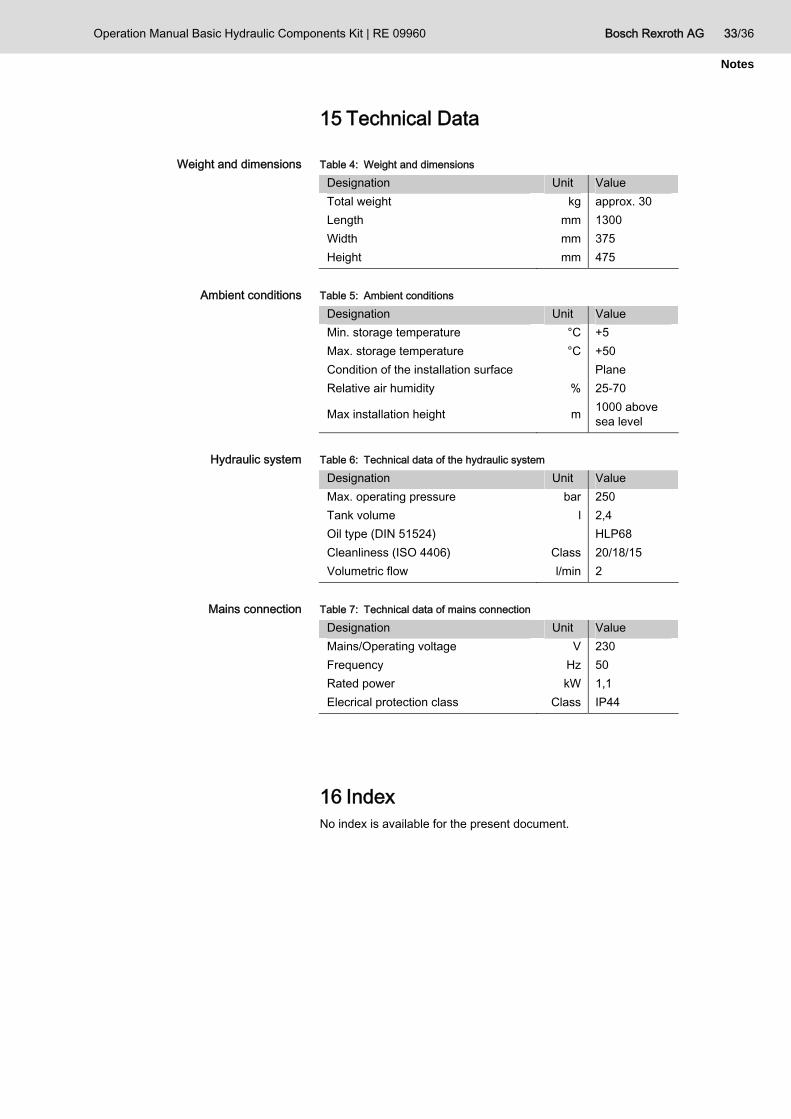
15 Technical Data
Weight and dimensions Table 4: Weight and dimensions Designation Unit Value Total weight kg approx. 30 Length mm 1300 Width mm 375 Height mm 475
Ambient conditions Table 5: Ambient conditions
Designation Unit Value Min. storage temperature °C +5 Max. storage temperature °C +50 Condition of the installation surface Plane Relative air humidity % 25-70
Max installation height m 1000 above sea level
Hydraulic system Table 6: Technical data of the hydraulic system
Designation Unit Value Max. operating pressure bar 250 Tank volume l 2,4 Oil type (DIN 51524) HLP68 Cleanliness (ISO 4406) Class 20/18/15 Volumetric flow l/min 2
Mains connection Table 7: Technical data of mains connection
Designation Unit Value Mains/Operating voltage V 230 Frequency Hz 50 Rated power kW 1,1 Elecrical protection class Class IP44
16 Index No index is available for the present document.

34/36 Bosch Rexroth AG Operation Manual Basic Hydraulic Components Kit | RE 09960
Notes
The data specifed above only
serve to describe the product. No statements concerning a certain condition or suitability for a certain application can be derived from our information. The information given does not release the user from the obligation of own
judgment and verification. It must be rememebered that our products are subject to a natural process of wear and aging.
© This document, as well as the data, specifications and other information set forth in it, are the exclusive property of Bosch Rexroth AG. It may not be reproduced or given to third parties without its consent.
Subjet to revision. Printed in Germany.
RE 09960-B/04.08
M
at. - Nr. R961004689

Operation Manual Basic Hydraulic Components Kit | RE 09960 Bosch Rexroth AG 35/36
Notes

Bosch Rexroth AG Training & Didactic Maria-Theresien-Str. 23 D-97816 Lohr am Main, Germany Phone +49 (0) 93 52 / 18-10 41 Fax +49 (0) 93 52 / 18-10 40 [email protected] www.boschrexroth.com
The data specifed above only serve to describe the product. No statements concerning a certain condition or suitability for a certain application can be derived from our information. The information given does not release the user from the obligation of own judgment and verification. It must be rememebered that our products are subject to a natural process of wear and aging.
© This document, as well as the data, specifications and other information set forth in it, are the exclusive property of Bosch Rexroth AG. It may not be reproduced or given to third parties without its consent.
Subjet to revision. Printed in Germany.
RE 09960-B/04.08
Mat. - Nr. R961004689


