

Biomass research at CNRS Nancy
Research on biomass thermo-chemical conversion done in the CNRS-LRGP
Short overview
1/2013
The lab has privileged links with INPL (National PolytechnicInstitute of Lorraine) which is a part of Lorraine University
The lab is hosted in two Engineering schools in INPL� National school for industrial chemistry (ENSIC)
� National school of agronomy and food industry (ENSAIA)
Laboratory of Reactions and Processes Engineering (LRGP) – UPR CNRS 3349
A national laboratory of the french CNRS (National Center for Scientific Research), within the Institute of Engineering Sciences and Systems
The lab is composed of ~ 300 persons� 30 research scientists (CNRS)� 80 professors and lecturers� 50 technical or administrative staff members� 140 PhD students or post-doc scientists� Head of the lab : Gabriel Wild
Deputy director : Jean-Pierre Leclerc
- 2 -
BIOMASS feedstock(lignin, hemicelluloses and cellulose)
Main routes studied at LRGP for biomass conversion
Combustion
T>800°CO2
CO2 + H2O+ ashes
Heat and/or
electricity
Syngas
T=200-1000°CNo O2
Pyrolysis
Char
Liquefaction
T=200 - 400 °CPH2=20-200 Bars
Bio-oils
Electricity, liquid biofuels, Gaseous biofuels (CH4, H2,), etc.
T=700-1500°C
~1/3 O2
Gasification
Biofuels, chemicals
+ Up-grading Gasification Refineries
- 3 -
Multi-scale approach to optimize the processes
Scale
Topics
Molecule Particle Reactor Process
Tar conversion
Particle modelling
Reactor modelling
Energetic optimisation of
processes
Process modelling (Aspen)
Pyrolysis and
gasification reactors
Gas/solid reactions (char
oxidation, catalysis)
Chemical kinetic
Mechanisms of solid pyrolysis
- 4 -
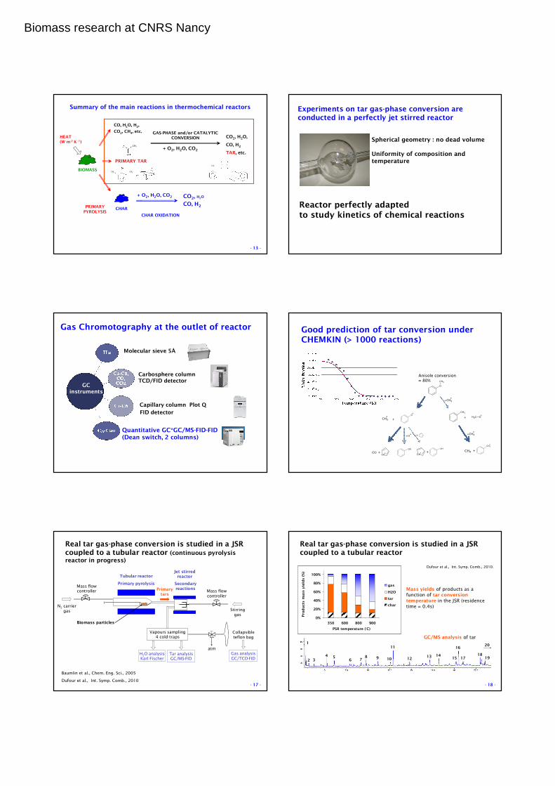
Summary of the main reactions in thermochemical reactors
BIOMASS
CO, H2O, H2,
CO2, CH4, etc.
PRIMARY TAR
CHARPRIMARY PYROLYSIS
HEAT (W m-2 K -1)
+ O2, H2O, CO2
GAS-PHASE and/or CATALYTIC CONVERSION CO2, H2O,
CO, H2
TAR, etc.
CO2, H2O
CO, H2
CHAR OXIDATION
+ O2, H2O, CO2
CH3
CH3 CH3
CH3
- 5 -
Primary pyrolysis of biomass
Polymers carefully extracted from the biomass network (by Pr. Brosse)
Thermogravimetry (TG) - differential scanning calorimetry (DSC)
0
20
40
60
80
100
150 250 350 450
Temperature (°C)
Mass f
ractio
n (
%)
(m
ass /
in
itia
l m
ass)
Xylan
Miscanthus
Cellulose
Lignin
5 K min-1, ~ 1mg initial sample
- 6 -
Quantitative DSC in a 3D sensor
(Setaram, France)

Biomass research at CNRS Nancy
In-situ analysis of biomass pyrolysis by 1H NMR (with
Pr. Snape group, Nottingham) and rheology (see ACS meeting, San Diego)
Mobility of protons are analysed by in-situ 1H NMRInteractions between polymers in the native network
- 7 -
Dufour et al., ChemSusChem, 2012
Visco-elastic, swelling and shrinking properties are analysed by rheometry (mechanical spectroscopy).
- 8 -
Transducer
Motor
Biomass pellet (~2mm)
2 parallel plates
Normal force (200g)
0
1
2
150 200 250 300 350 400
Temperature (°C)
tan
(δδ δδ)
Xylan
Miscanthus
Cellulose
LigninMainly
VISCOUS
Mainly
ELASTIC
Mechanisms of softening and resolidification (“char formation”) are evidenced.
Energy&Fuels, 2012
Summary of the main reactions in thermochemical reactors
BIOMASS
CO, H2O, H2,
CO2, CH4, etc.
PRIMARY TAR
CHARPRIMARY PYROLYSIS
HEAT (W m-2 K -1)
+ O2, H2O, CO2
GAS-PHASE and/or CATALYTIC CONVERSION CO2, H2O,
CO, H2
TAR, etc.
CO2, H2O
CO, H2
CHAR OXIDATION
+ O2, H2O, CO2
CH3
CH3 CH3
CH3
- 9 -
Char oxidation and reactivity
TG – DSC + IR or µGC analysis, fixed bed oxidation, etc.
Molecular structure of charsis analysed by High ResolutionTransmission Elec. Miscroscopy (with J.N. Rouzaud, Paris)
2nm
Mineral impurity
Carbon sheets
Analysis at nm scale
Carbon sheets of wood char like a “crumpled” paper.
- 10 -
Differential thermal annealing is an original method to characterize different “types” of carbons in char
- 11 -
Graphite fritted
Graphite support
Reactive & carrier gas
Thermocouple
Pyrometerspot
Particles
External carrier gas
A new set-up has been designed: heating of char up to 1800°C (in 30s) in a fixed bed
Heating of chars to 1800°C followed by XRD analysis allows to reveal different types of carbons and reactivity in chars.
- 12 -
5 15 25 35 45 55 65
Diffraction angle (2θθθθ, degree)
Inte
nsit
y (a
rbit
rary
uni
ts)
Char 2
*
Char 3
Char 4
Biomass research at CNRS Nancy
Summary of the main reactions in thermochemical reactors
BIOMASS
CO, H2O, H2,
CO2, CH4, etc.
PRIMARY TAR
CHARPRIMARY PYROLYSIS
HEAT (W m-2 K -1)
+ O2, H2O, CO2
GAS-PHASE and/or CATALYTIC CONVERSION CO2, H2O,
CO, H2
TAR, etc.
CO2, H2O
CO, H2
CHAR OXIDATION
+ O2, H2O, CO2
CH3
CH3 CH3
CH3
- 13 -
Experiments on tar gas-phase conversion are conducted in a perfectly jet stirred reactor
Spherical geometry : no dead volume
Uniformity of composition and temperature
Reactor perfectly adapted to study kinetics of chemical reactions
GC instruments
Carbosphere columnTCD/FID detector
Capillary column Plot Q
FID detector
Molecular sieve 5Å
Gas Chromotography at the outlet of reactor
Quantitative GC*GC/MS-FID-FID (Dean switch, 2 columns)
Good prediction of tar conversion underCHEMKIN (> 1000 reactions)
O
CH3
CH3
OCH3 O
CH3
COCH
OH OH
CH
H
CH2
CH4
+ +
+
+ +
+CH3
+
+
+CH3
Anisole conversion = 80%
Real tar gas-phase conversion is studied in a JSR coupled to a tubular reactor (continuous pyrolysis reactor in progress)
Baumlin et al., Chem. Eng. Sci., 2005
Dufour et al., Int. Symp. Comb., 2010
Mass flowcontroller
H2O analysisKarl Fischer
Tar analysisGC/MS-FID
atm
Collapsible teflon bag
Gas analysisGC/TCD-FID
Mass flow controller
Jet stirred reactor
Secondaryreactions
Tubular reactor
Primary pyrolysis
N2 carrier gas Stirring
gas
Biomass particles
Primarytars
Vapours sampling4 cold-traps
- 17 -
Dufour et al., Int. Symp. Comb., 2010.
0%
20%
40%
60%
80%
100%
350 600 800 900
PSR temperature (°C)
Pro
du
cts m
ass y
ield
s (
%)
gas
H2O
tar
char
1
2 34 5
6 78 9 10
11
1213 14
15
16
1718
19
201
2 34 5
6 78 9 10
11
1213 14
15
16
1718
19
20
Mass yields of products as a function of tar conversion temperature in the JSR (residence time = 0.4s)
GC/MS analysis of tar
Real tar gas-phase conversion is studied in a JSR coupled to a tubular reactor
- 18 -

Biomass research at CNRS Nancy
TAR catalytic conversion is studied in fixed bed reactor for tarcracking in gasification reactor or for tar hydro-deoxygenation
2 impingerswith propanol
(-60°C)
T
Vent
µGC - 4 modulesOn-line analysis
(CH4, H2, CO, etc.)To GC-FID-MSIntegral off-line analysis
Heated lines
Catalyst bed
Syringe pump
Oven
Fritted
Mass Flow Controllers
H2
N2
CO
CH4
4 ways valve
R. Olcese pH-D
- 19 -
Production of aromatic chemicals (benzene, etc.) from never-condensed lignin pyrolysis vapours
- 20 -
0
0.1
0.2
0.3
0.4
0.5
0.4 0.9 1.4 1.9 2.4
H/C
O/C
Lignins
Pyrolytic oil
Cyclo- hexanol
AlkanesBTX
O
OH
OH
O
O
OH
OH
LigninO
CH3
O
Lignin
O
O
CH3
O
OH
Lignin
CH3
CH3
O
OH
CH3
CH3 CH3
CH3
CH3CH3
Desired route
Undesired route
Pyrolysis
Guaiacol
Very good selectivity in BT (Benzene, Toluene) production from guaiacol with Fe/SiO2 catalyst: green and cheap catalyst
- 21 -Olcese et al., App. Catal. B., 2012 & 2013.
Mass residence time= 1/WHSV = g catalyst/(g guaiacol/h)
Multi-scale approach to optimize the processes
Scale
Topics
Molecule Particle Reactor Process
Tar conversion
Particle modelling
Reactor modelling
Energetic optimisation of
processes
Process modelling (Aspen)
Pyrolysis and
gasification reactors
Gas/solid reactions (char
oxidation, catalysis)
Chemical kinetic
Mechanisms of solid pyrolysis
- 22 -
Wood char particles, slow pyrolysis, from mm to µm (Scanning Electron Microscope): bubbles formation at µm length scale (Dufour et al., App. Catal., 2008)
Intra-particular mass transfer of pyrolysis products
High heat flux density (Boutin et al. 1998)
Cellulose before pyrolysis After pyrolysis
- 23 -
Modelling of biomass primary pyrolysis
A simplified model has been proposed including:
Modified Bradbury (1979) mechanism + intermediate liquidcompounds + evaporation of liquid tar + intra-particle conversion
γγγγ Gas + (1-γγγγ) CharBiomass1
Intermediate solid2
3
Liquid tar Evaporated tar
δ δ δ δ Gas + (1-δδδδ) Char
4
Intra-particle tar evaporation (thermodynamic equilibrium)
(Fletcher et al., 1991)
)T
M*Bexp(AP
59.0T
TG
−=
Internal mass transfer by convection (Darcy law)
L
PS
KQ
G
∆µ
=
bRT
E
ii
i
eAr ρ−
=
Dufour et al., Chem. Eng. Res. Des., 2011
Kinetic of 4 reactions
- 24 -

Biomass research at CNRS Nancy
Modelling of primary pyrolysis
Comparison between model and experiments (from Milosavljevic and Suuberg,1995)
for different heating rates
Mass loss controlled by intra-particle liquid tar conversion, in agreement withSuuberg (1996)
Dufour et al., Chem. Eng. Res. Des., 2011
0.0
0.2
0.4
0.6
0.8
1.0
500 600 700 800
Temperature (K)
Mas
s lo
ss
a = 16.67 K/s
a = 1.67 K/s
a = 0.097 K/s
0.0
0.2
0.4
0.6
0.8
1.0
500 600 700 800
Temperature (K)
Mas
s fr
acti
on
Mass loss
Y B
Y I
Y TL
Y S1
Y S2
- 25 -
Heating of particle surface by xenon-arc lamp radiation = controlledheat flux density (~0.5MW/m2)
Primary vapours are immediately quenched at the outlet of the particle
Experiments on primary pyrolysis are conducted by the image furnace (Lédé, 1982, Authier et al., Ind. Eng. Chem Res., 2009)
- 26 -
Modelling of primary pyrolysis(Authier, I&ECR, 2009, Al Haddad, En&Fuels, 2009)
Simplified chemical mechanism
1D mass and energy balance
biomass
gas
tar
char
bRT
E
ii
i
eAr ρ−
=
∑∆−∂∂=
∂∂
+i
iizpccpbb rHz
T
t
TCC
2
2
)( λρρ
∑=∂
∂
iiij
j rt
νρMass balance
Energy balance
Without any internal mass transfer
- 27 -
Comparison between experiments from image furnace and model predictions with different kinetic rate constants (Authier, Mauviel, 2009)
0%
10%
20%
30%
40%
50%
60%
70%
80%
90%
100%
0 5 10 15 20 25 30 35 40
Temps (s )
Pe
rte
s
/ M
as
se
in
itia
le d
u b
ois
) %
1,4 mm - 78 % oc c ultation
0,5 mm - 78 % oc c ultation
0,5 mm - 39 % oc c ultation
T hurner
C han
Di B las i
Wag enaar
F ont
Mass loss /
init
ial m
ass d
ry w
ood (
%)
Time (s)
Important effect of kinetic parameters
- 28 -
Multi-scale approach to optimize the processes
Scale
Topics
Molecule Particle Reactor Process
Tar conversion
Particle modelling
Reactor modelling
Energetic optimisation of
processes
Process modelling (Aspen)
Pyrolysis and
gasification reactors
Gas/solid reactions (char
oxidation, catalysis)
Chemical kinetic
Mechanisms of solid pyrolysis
- 29 -
Reactors for biomass pyrolysis and gasification
The cyclone is a multi-functional reactor for fast pyrolysis (Lédéat al., 1990, 2000)
Complete hydrodynamic & thermal modelling
Fluidised bed gasification reactors are developed up to 50kg/h(in a collaborative facility with EDF – French Power Company)
Biomass particles
Char
Gases
Condensers
& Filters
Bio-oils
Carrier gas
Heating of
the wallFast pyrolysis +
separation of char
Analysis
Analysis
- 30 -

Biomass research at CNRS Nancy
Biomass3 t/h
Steam500 kg/h
Air
CO2, H2O, N2
H2 + CO + CO2 + CH4 + H2O + TAR
T= 850°C
Cokedolivine +
char
Olivine 140 t/h
Modelling of the dual fluidised bed of Güssing (Austria)(Authier O. , ph-D for EDF, J. Lédé & G. Mauviel)
Dense bed model:
Fluidised bed hydrodynamic
Steam and heat transfer to biomass particle
Particle model (internal heat transfer, drying, pyrolysis, char gasification)
Gas-phase reactions
Freeboard model:
Kinetics of:
Water Gas Shift,
Methane reforming
Gas-phase and catalytic tar conversion
+ enthalpy balance
T= 950°C
- 31 -
Multi-scale approach to optimize the processes
Scale
Topics
Molecule Particle Reactor Process
Tar conversion
Particle modelling
Reactor modelling
Energetic optimisation of
processes
Process modelling (Aspen)
Pyrolysis and
gasification reactors
Gas/solid reactions (char
oxidation, catalysis)
Chemical kinetic
Mechanisms of solid pyrolysis
- 32 -
Coupling between Aspen software and Fortran allowsa more detailed modelling of processes
More detailed reactor modelling under ASPEN thanks to Fortran files
More detailed products compositions, mass and enthalpybalances
Process flow sheet
Products data base
Mass and enthalpy
flow rates
Aspen
Detailed reactor
modelling
Mass balance
Kinetic model
FortranReactor
inlet
Reactor
outlet
- 33 -Abdelouahed, submitted to En& Fuels
55
60
65
70
Eff
icie
ncy
(%
)
A biomass gasification process was modelledunder Aspen Plus
The efficiency of the process is improvedby catalytic tar conversion over char
Char is a green catalystfor tar cracking Tar cracking
over char
Base
process
Optimised
process
App. Catal., 2008
Abdelouahed, En& Fuels, 2012
Francois, Biomass Bioenergy, in press
- 34 -
Aspen models are used to optimise gasification processes
Modelling of biomass conditionning and pretreatment
Modelling of a whole gasification processfrom forests to power with minerals and NOx, SOx, etc. emissions
Life cycle assessment of a combined heatand power plant based on the detailedAspen mass and energy balances
- 35 -
In CNRS-LRGP laboratory, research on biomass
thermo-chemical conversion are conducted on:
pyrolysis and gasification,
a multi-scale approach, from molecular to
process scale.
Nancy and its wonderful Stanislas square!
- 36 -

Biomass research at CNRS Nancy
Thank you for your attention
- 37 -Thank you to all the contributors ( > 40 people)
KinCom and GREENER groups
- 38 -
Summary of LRGP set-ups and models for biomassthermochemical conversion
Reactors: from 20 to 2000°C
• TG-DSC
• Image furnace and laser heating (imposed heat flux density)
• Catalytic fixed bed
• High temperature fixed bed (up to 2000°C)
• JSRs for tar (model or real compounds) gas-phase conversion
• Cyclone reactor
• Fluidised beds (lab scale 3Kg/h and pilot scale 50kg/h, under development.)
Analysis
• Solid analysis: elemental analysis, ICP-MS & AES, MEB, N2 sorption, Hg porosim., Raman, IRTF, etc.
• Liquid analysis: LC-MS-UV-RI, GC*GC/MS-FID
• Gas analysis: 3 µGC, many GCs, on line IR, etc.
Models
• CHEMKIN
• ASPEN/FORTRAN
- 38 -


![arXiv:1903.06035v1 [quant-ph] 13 Mar 2019 · e-mailaddress: simon.perdrix@loria.fr Universit´e de Lorraine, CNRS, Inria, LORIA, F 54000 Nancy, France e-mailaddress: renaud.vilmart@loria.fr](https://static.documents.pub/doc/80x56/5f533a34e762445a8c79da78/arxiv190306035v1-quant-ph-13-mar-2019-e-mailaddress-simonperdrixloriafr.jpg)
