
Project
First Saved Tuesday, October 25, 2016
Last Saved Tuesday, October 25, 2016
Product Version 16.0 Release
Save Project Before Solution No
Save Project After Solution No
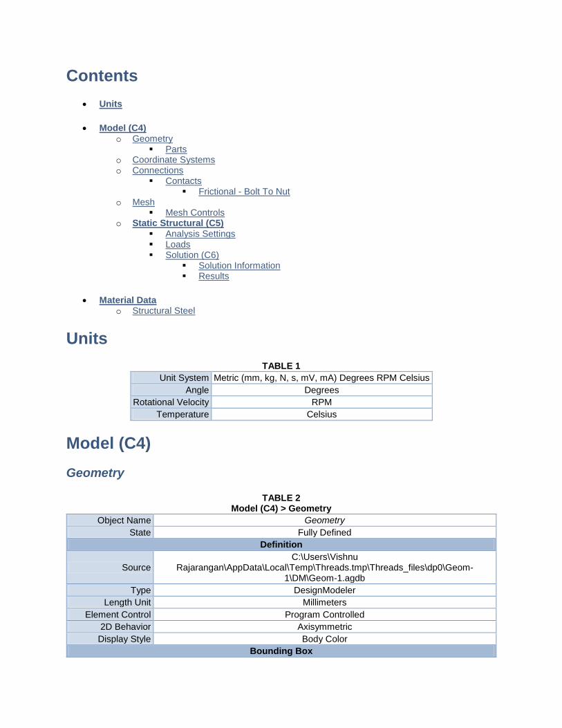
Contents
Units
Model (C4) o Geometry
Parts o Coordinate Systems o Connections
Contacts Frictional - Bolt To Nut
o Mesh Mesh Controls
o Static Structural (C5) Analysis Settings Loads Solution (C6)
Solution Information Results
Material Data o Structural Steel
Units
TABLE 1
Unit System Metric (mm, kg, N, s, mV, mA) Degrees RPM Celsius
Angle Degrees
Rotational Velocity RPM
Temperature Celsius
Model (C4)
Geometry
TABLE 2 Model (C4) > Geometry
Object Name Geometry
State Fully Defined
Definition
Source C:\Users\Vishnu
Rajarangan\AppData\Local\Temp\Threads.tmp\Threads_files\dp0\Geom-1\DM\Geom-1.agdb
Type DesignModeler
Length Unit Millimeters
Element Control Program Controlled
2D Behavior Axisymmetric
Display Style Body Color
Bounding Box
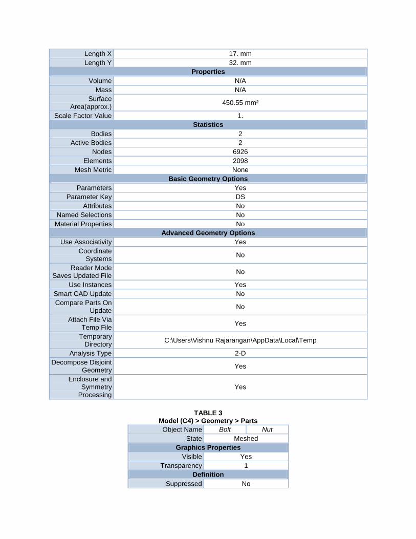
Length X 17. mm
Length Y 32. mm
Properties
Volume N/A
Mass N/A
Surface Area(approx.)
450.55 mm²
Scale Factor Value 1.
Statistics
Bodies 2
Active Bodies 2
Nodes 6926
Elements 2098
Mesh Metric None
Basic Geometry Options
Parameters Yes
Parameter Key DS
Attributes No
Named Selections No
Material Properties No
Advanced Geometry Options
Use Associativity Yes
Coordinate Systems
No
Reader Mode Saves Updated File
No
Use Instances Yes
Smart CAD Update No
Compare Parts On Update
No
Attach File Via Temp File
Yes
Temporary Directory
C:\Users\Vishnu Rajarangan\AppData\Local\Temp
Analysis Type 2-D
Decompose Disjoint Geometry
Yes
Enclosure and Symmetry
Processing Yes
TABLE 3 Model (C4) > Geometry > Parts
Object Name Bolt Nut
State Meshed
Graphics Properties
Visible Yes
Transparency 1
Definition
Suppressed No
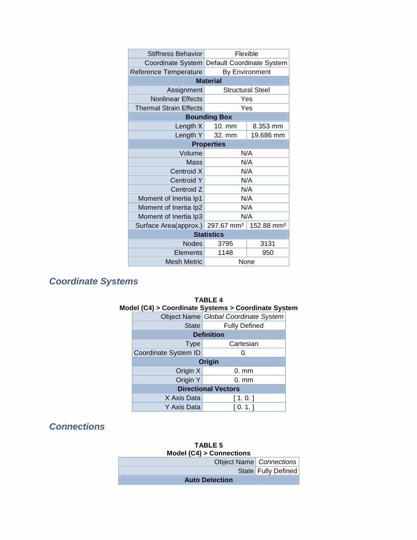
Stiffness Behavior Flexible
Coordinate System Default Coordinate System
Reference Temperature By Environment
Material
Assignment Structural Steel
Nonlinear Effects Yes
Thermal Strain Effects Yes
Bounding Box
Length X 10. mm 8.353 mm
Length Y 32. mm 19.686 mm
Properties
Volume N/A
Mass N/A
Centroid X N/A
Centroid Y N/A
Centroid Z N/A
Moment of Inertia Ip1 N/A
Moment of Inertia Ip2 N/A
Moment of Inertia Ip3 N/A
Surface Area(approx.) 297.67 mm² 152.88 mm²
Statistics
Nodes 3795 3131
Elements 1148 950
Mesh Metric None
Coordinate Systems
TABLE 4 Model (C4) > Coordinate Systems > Coordinate System
Object Name Global Coordinate System
State Fully Defined
Definition
Type Cartesian
Coordinate System ID 0.
Origin
Origin X 0. mm
Origin Y 0. mm
Directional Vectors
X Axis Data [ 1. 0. ]
Y Axis Data [ 0. 1. ]
Connections
TABLE 5 Model (C4) > Connections
Object Name Connections
State Fully Defined
Auto Detection
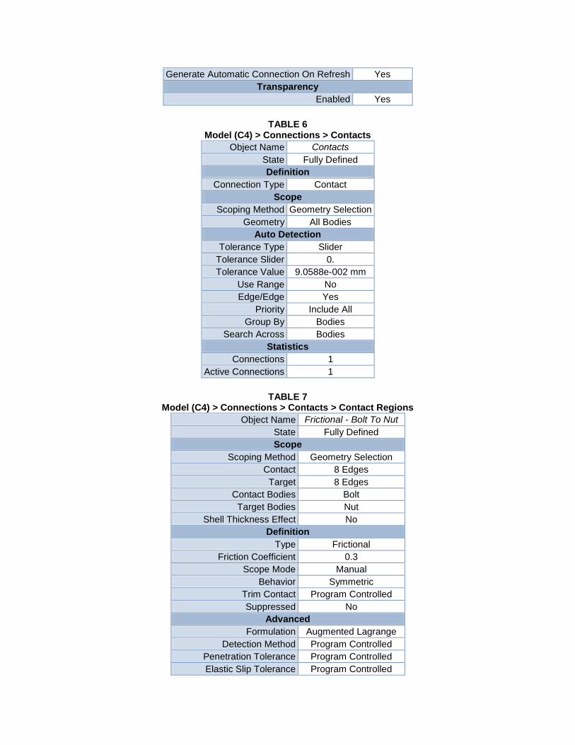
Generate Automatic Connection On Refresh Yes
Transparency
Enabled Yes
TABLE 6 Model (C4) > Connections > Contacts
Object Name Contacts
State Fully Defined
Definition
Connection Type Contact
Scope
Scoping Method Geometry Selection
Geometry All Bodies
Auto Detection
Tolerance Type Slider
Tolerance Slider 0.
Tolerance Value 9.0588e-002 mm
Use Range No
Edge/Edge Yes
Priority Include All
Group By Bodies
Search Across Bodies
Statistics
Connections 1
Active Connections 1
TABLE 7 Model (C4) > Connections > Contacts > Contact Regions
Object Name Frictional - Bolt To Nut
State Fully Defined
Scope
Scoping Method Geometry Selection
Contact 8 Edges
Target 8 Edges
Contact Bodies Bolt
Target Bodies Nut
Shell Thickness Effect No
Definition
Type Frictional
Friction Coefficient 0.3
Scope Mode Manual
Behavior Symmetric
Trim Contact Program Controlled
Suppressed No
Advanced
Formulation Augmented Lagrange
Detection Method Program Controlled
Penetration Tolerance Program Controlled
Elastic Slip Tolerance Program Controlled
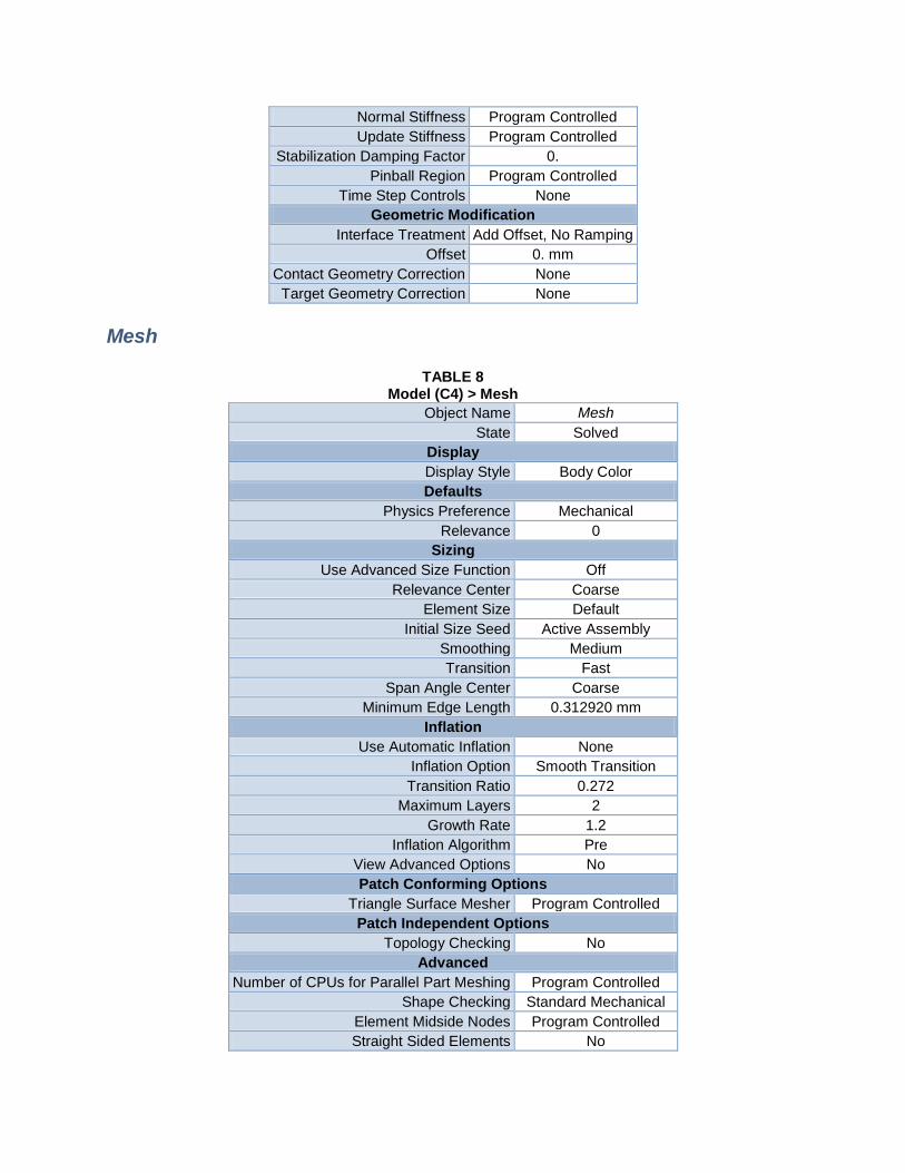
Normal Stiffness Program Controlled
Update Stiffness Program Controlled
Stabilization Damping Factor 0.
Pinball Region Program Controlled
Time Step Controls None
Geometric Modification
Interface Treatment Add Offset, No Ramping
Offset 0. mm
Contact Geometry Correction None
Target Geometry Correction None
Mesh
TABLE 8 Model (C4) > Mesh
Object Name Mesh
State Solved
Display
Display Style Body Color
Defaults
Physics Preference Mechanical
Relevance 0
Sizing
Use Advanced Size Function Off
Relevance Center Coarse
Element Size Default
Initial Size Seed Active Assembly
Smoothing Medium
Transition Fast
Span Angle Center Coarse
Minimum Edge Length 0.312920 mm
Inflation
Use Automatic Inflation None
Inflation Option Smooth Transition
Transition Ratio 0.272
Maximum Layers 2
Growth Rate 1.2
Inflation Algorithm Pre
View Advanced Options No
Patch Conforming Options
Triangle Surface Mesher Program Controlled
Patch Independent Options
Topology Checking No
Advanced
Number of CPUs for Parallel Part Meshing Program Controlled
Shape Checking Standard Mechanical
Element Midside Nodes Program Controlled
Straight Sided Elements No
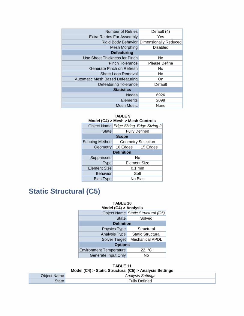
Number of Retries Default (4)
Extra Retries For Assembly Yes
Rigid Body Behavior Dimensionally Reduced
Mesh Morphing Disabled
Defeaturing
Use Sheet Thickness for Pinch No
Pinch Tolerance Please Define
Generate Pinch on Refresh No
Sheet Loop Removal No
Automatic Mesh Based Defeaturing On
Defeaturing Tolerance Default
Statistics
Nodes 6926
Elements 2098
Mesh Metric None
TABLE 9 Model (C4) > Mesh > Mesh Controls
Object Name Edge Sizing Edge Sizing 2
State Fully Defined
Scope
Scoping Method Geometry Selection
Geometry 16 Edges 15 Edges
Definition
Suppressed No
Type Element Size
Element Size 0.1 mm
Behavior Soft
Bias Type No Bias
Static Structural (C5)
TABLE 10 Model (C4) > Analysis
Object Name Static Structural (C5)
State Solved
Definition
Physics Type Structural
Analysis Type Static Structural
Solver Target Mechanical APDL
Options
Environment Temperature 22. °C
Generate Input Only No
TABLE 11 Model (C4) > Static Structural (C5) > Analysis Settings
Object Name Analysis Settings
State Fully Defined
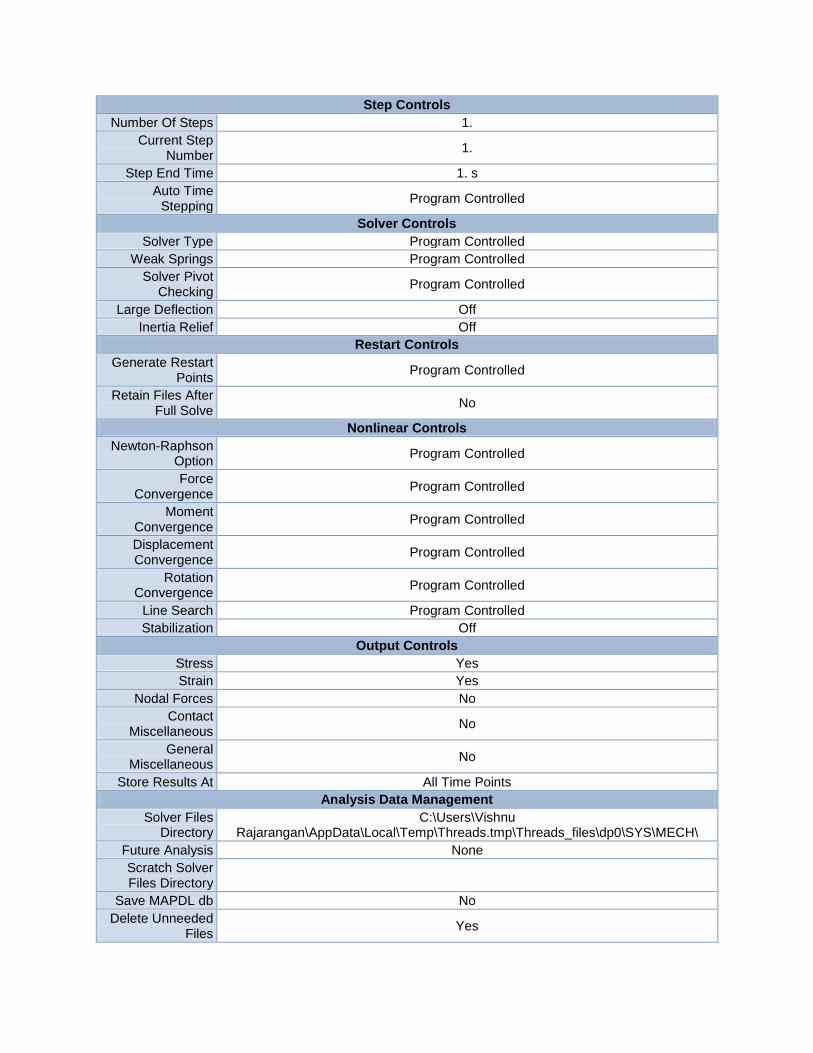
Step Controls
Number Of Steps 1.
Current Step Number
1.
Step End Time 1. s
Auto Time Stepping
Program Controlled
Solver Controls
Solver Type Program Controlled
Weak Springs Program Controlled
Solver Pivot Checking
Program Controlled
Large Deflection Off
Inertia Relief Off
Restart Controls
Generate Restart Points
Program Controlled
Retain Files After Full Solve
No
Nonlinear Controls
Newton-Raphson Option
Program Controlled
Force Convergence
Program Controlled
Moment Convergence
Program Controlled
Displacement Convergence
Program Controlled
Rotation Convergence
Program Controlled
Line Search Program Controlled
Stabilization Off
Output Controls
Stress Yes
Strain Yes
Nodal Forces No
Contact Miscellaneous
No
General Miscellaneous
No
Store Results At All Time Points
Analysis Data Management
Solver Files Directory
C:\Users\Vishnu Rajarangan\AppData\Local\Temp\Threads.tmp\Threads_files\dp0\SYS\MECH\
Future Analysis None
Scratch Solver Files Directory
Save MAPDL db No
Delete Unneeded Files
Yes
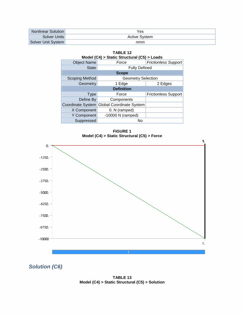
Nonlinear Solution Yes
Solver Units Active System
Solver Unit System nmm
TABLE 12 Model (C4) > Static Structural (C5) > Loads
Object Name Force Frictionless Support
State Fully Defined
Scope
Scoping Method Geometry Selection
Geometry 1 Edge 2 Edges
Definition
Type Force Frictionless Support
Define By Components
Coordinate System Global Coordinate System
X Component 0. N (ramped)
Y Component -10000 N (ramped)
Suppressed No
FIGURE 1 Model (C4) > Static Structural (C5) > Force
Solution (C6)
TABLE 13 Model (C4) > Static Structural (C5) > Solution
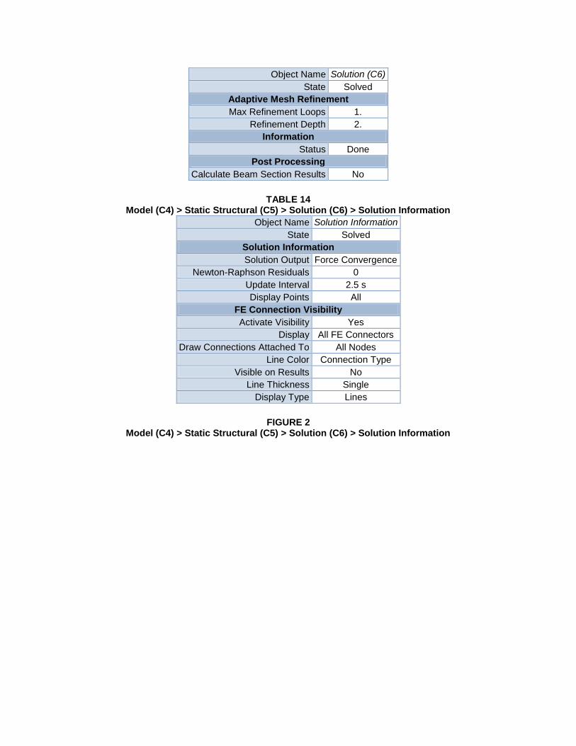
Object Name Solution (C6)
State Solved
Adaptive Mesh Refinement
Max Refinement Loops 1.
Refinement Depth 2.
Information
Status Done
Post Processing
Calculate Beam Section Results No
TABLE 14 Model (C4) > Static Structural (C5) > Solution (C6) > Solution Information
Object Name Solution Information
State Solved
Solution Information
Solution Output Force Convergence
Newton-Raphson Residuals 0
Update Interval 2.5 s
Display Points All
FE Connection Visibility
Activate Visibility Yes
Display All FE Connectors
Draw Connections Attached To All Nodes
Line Color Connection Type
Visible on Results No
Line Thickness Single
Display Type Lines
FIGURE 2 Model (C4) > Static Structural (C5) > Solution (C6) > Solution Information
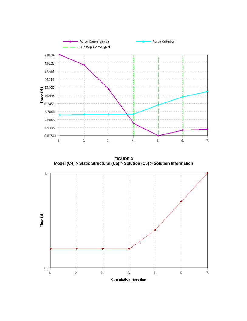
FIGURE 3 Model (C4) > Static Structural (C5) > Solution (C6) > Solution Information
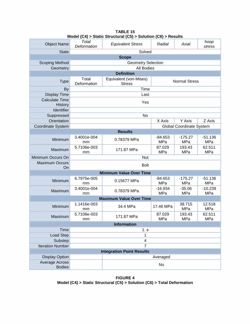
TABLE 15 Model (C4) > Static Structural (C5) > Solution (C6) > Results
Object Name Total
Deformation Equivalent Stress Radial Axial
hoop stress
State Solved
Scope
Scoping Method Geometry Selection
Geometry All Bodies
Definition
Type Total
Deformation Equivalent (von-Mises)
Stress Normal Stress
By Time
Display Time Last
Calculate Time History
Yes
Identifier
Suppressed No
Orientation X Axis Y Axis Z Axis
Coordinate System Global Coordinate System
Results
Minimum 3.4001e-004
mm 0.78379 MPa
-84.653 MPa
-175.27 MPa
-51.136 MPa
Maximum 5.7106e-003
mm 171.87 MPa
87.029 MPa
193.43 MPa
62.511 MPa
Minimum Occurs On Nut
Maximum Occurs On
Bolt
Minimum Value Over Time
Minimum 6.7975e-005
mm 0.15677 MPa
-84.653 MPa
-175.27 MPa
-51.136 MPa
Maximum 3.4001e-004
mm 0.78379 MPa
-16.934 MPa
-35.06 MPa
-10.239 MPa
Maximum Value Over Time
Minimum 1.1416e-003
mm 34.4 MPa 17.46 MPa
38.715 MPa
12.518 MPa
Maximum 5.7106e-003
mm 171.87 MPa
87.029 MPa
193.43 MPa
62.511 MPa
Information
Time 1. s
Load Step 1
Substep 4
Iteration Number 7
Integration Point Results
Display Option Averaged
Average Across Bodies
No
FIGURE 4 Model (C4) > Static Structural (C5) > Solution (C6) > Total Deformation
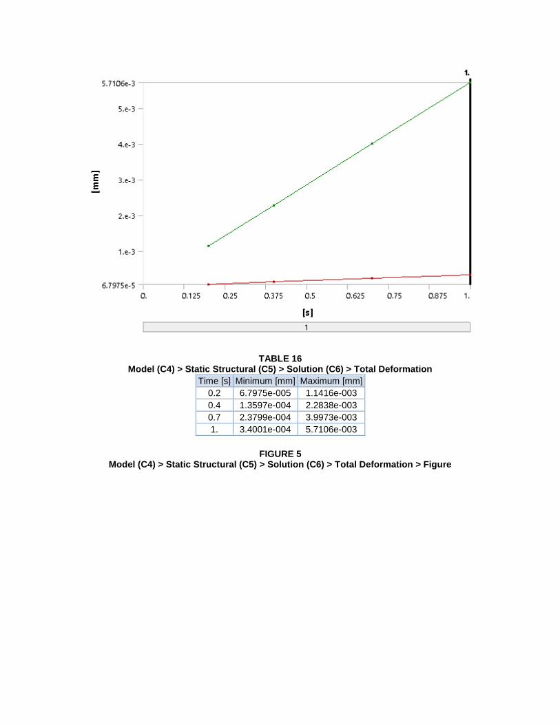
TABLE 16 Model (C4) > Static Structural (C5) > Solution (C6) > Total Deformation
Time [s] Minimum [mm] Maximum [mm]
0.2 6.7975e-005 1.1416e-003
0.4 1.3597e-004 2.2838e-003
0.7 2.3799e-004 3.9973e-003
1. 3.4001e-004 5.7106e-003
FIGURE 5 Model (C4) > Static Structural (C5) > Solution (C6) > Total Deformation > Figure
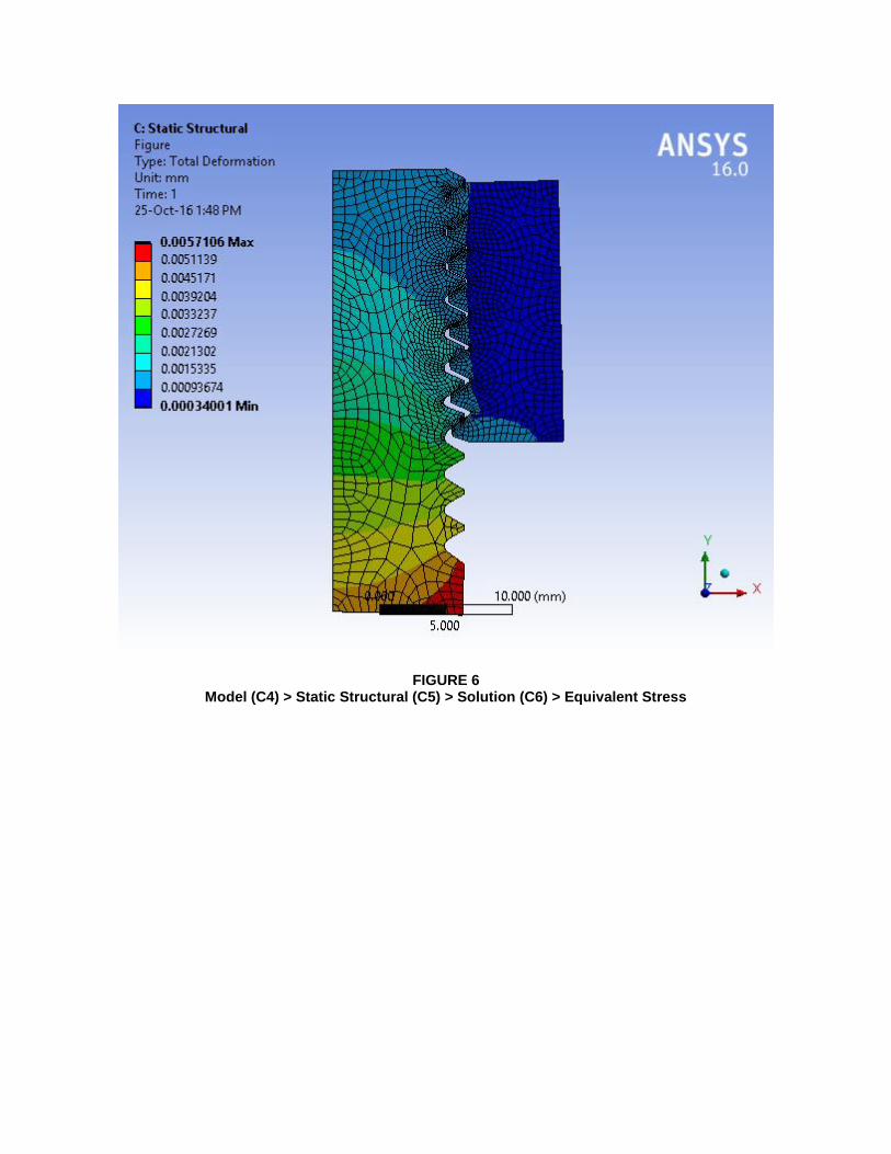
FIGURE 6 Model (C4) > Static Structural (C5) > Solution (C6) > Equivalent Stress
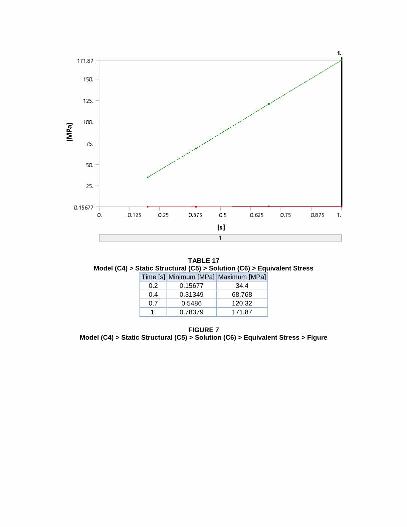
TABLE 17 Model (C4) > Static Structural (C5) > Solution (C6) > Equivalent Stress
Time [s] Minimum [MPa] Maximum [MPa]
0.2 0.15677 34.4
0.4 0.31349 68.768
0.7 0.5486 120.32
1. 0.78379 171.87
FIGURE 7 Model (C4) > Static Structural (C5) > Solution (C6) > Equivalent Stress > Figure
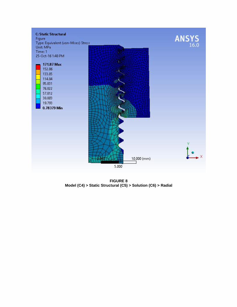
FIGURE 8 Model (C4) > Static Structural (C5) > Solution (C6) > Radial
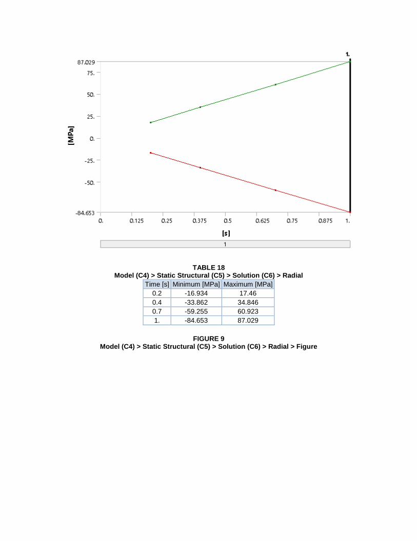
TABLE 18 Model (C4) > Static Structural (C5) > Solution (C6) > Radial
Time [s] Minimum [MPa] Maximum [MPa]
0.2 -16.934 17.46
0.4 -33.862 34.846
0.7 -59.255 60.923
1. -84.653 87.029
FIGURE 9 Model (C4) > Static Structural (C5) > Solution (C6) > Radial > Figure
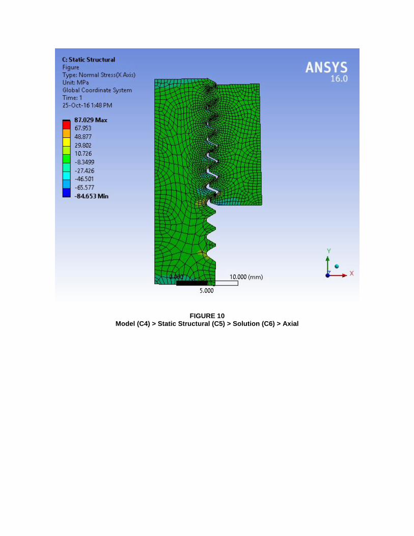
FIGURE 10 Model (C4) > Static Structural (C5) > Solution (C6) > Axial
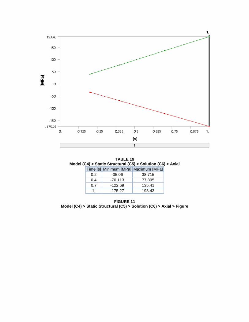
TABLE 19 Model (C4) > Static Structural (C5) > Solution (C6) > Axial
Time [s] Minimum [MPa] Maximum [MPa]
0.2 -35.06 38.715
0.4 -70.113 77.395
0.7 -122.69 135.41
1. -175.27 193.43
FIGURE 11 Model (C4) > Static Structural (C5) > Solution (C6) > Axial > Figure
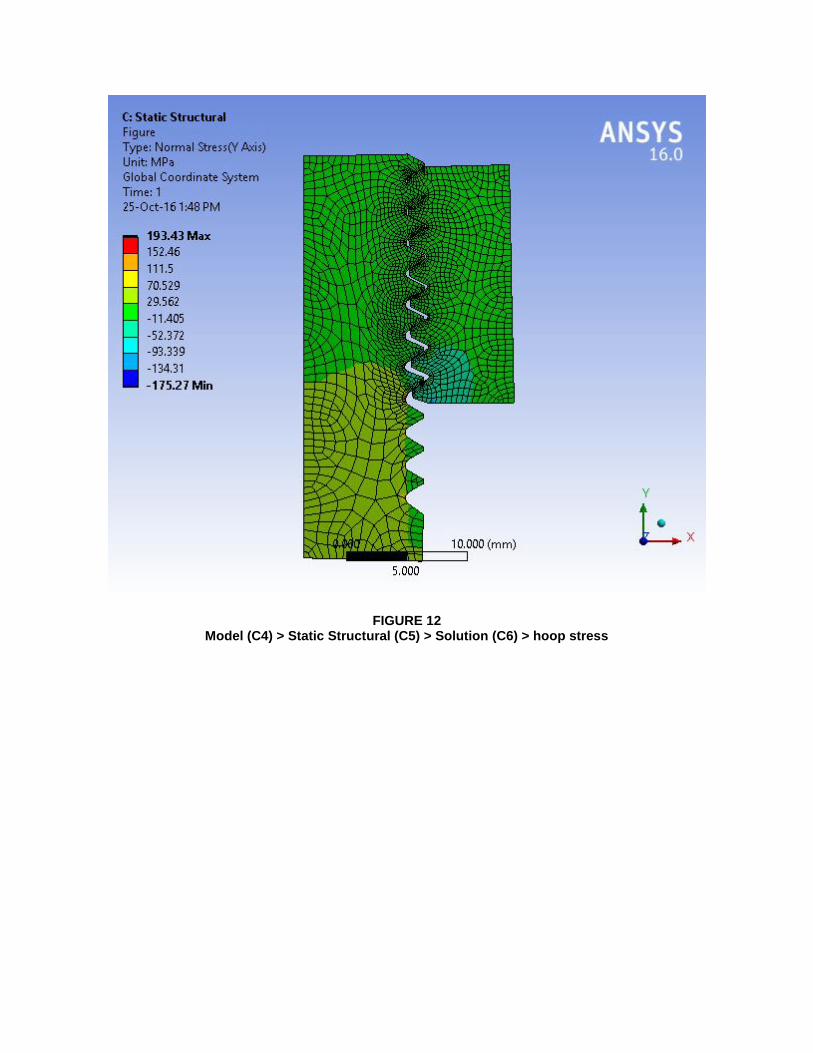
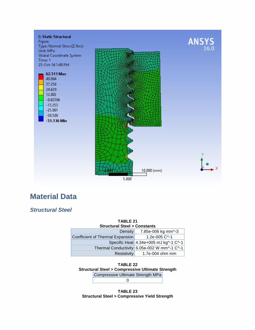
FIGURE 12 Model (C4) > Static Structural (C5) > Solution (C6) > hoop stress
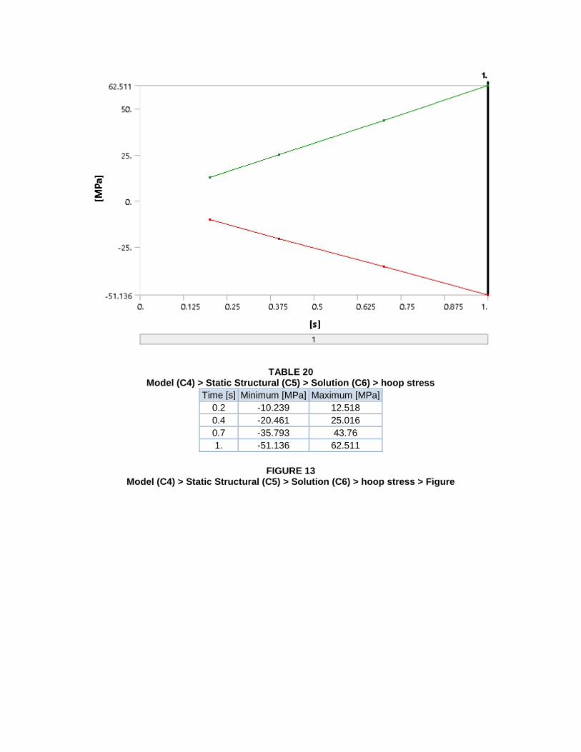
TABLE 20 Model (C4) > Static Structural (C5) > Solution (C6) > hoop stress
Time [s] Minimum [MPa] Maximum [MPa]
0.2 -10.239 12.518
0.4 -20.461 25.016
0.7 -35.793 43.76
1. -51.136 62.511
FIGURE 13 Model (C4) > Static Structural (C5) > Solution (C6) > hoop stress > Figure
Material Data
Structural Steel
TABLE 21 Structural Steel > Constants
Density 7.85e-006 kg mm^-3
Coefficient of Thermal Expansion 1.2e-005 C^-1
Specific Heat 4.34e+005 mJ kg^-1 C^-1
Thermal Conductivity 6.05e-002 W mm^-1 C^-1
Resistivity 1.7e-004 ohm mm
TABLE 22 Structural Steel > Compressive Ultimate Strength
Compressive Ultimate Strength MPa
0
TABLE 23 Structural Steel > Compressive Yield Strength
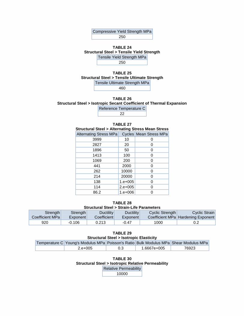
Compressive Yield Strength MPa
250
TABLE 24 Structural Steel > Tensile Yield Strength
Tensile Yield Strength MPa
250
TABLE 25 Structural Steel > Tensile Ultimate Strength
Tensile Ultimate Strength MPa
460
TABLE 26 Structural Steel > Isotropic Secant Coefficient of Thermal Expansion
Reference Temperature C
22
TABLE 27 Structural Steel > Alternating Stress Mean Stress
Alternating Stress MPa Cycles Mean Stress MPa
3999 10 0
2827 20 0
1896 50 0
1413 100 0
1069 200 0
441 2000 0
262 10000 0
214 20000 0
138 1.e+005 0
114 2.e+005 0
86.2 1.e+006 0
TABLE 28 Structural Steel > Strain-Life Parameters
Strength Coefficient MPa
Strength Exponent
Ductility Coefficient
Ductility Exponent
Cyclic Strength Coefficient MPa
Cyclic Strain Hardening Exponent
920 -0.106 0.213 -0.47 1000 0.2
TABLE 29 Structural Steel > Isotropic Elasticity
Temperature C Young's Modulus MPa Poisson's Ratio Bulk Modulus MPa Shear Modulus MPa
2.e+005 0.3 1.6667e+005 76923
TABLE 30 Structural Steel > Isotropic Relative Permeability
Relative Permeability
10000


