
BREATHERS & DRYERS: TANK VENT DRYERS
The first line of defense against lubricant contamination & fluid storage protection
Many fluids, chemicals, fuels, lubricants, semi-solids, and powders are seriously affected by moisture and other contaminants. Many of these materials which are affected are often stored in tanks or reservoirs which are either located in the open and vented to atmosphere or are located in the process area.
Fluid contaminants, such as moisture and dirt, will be ingress into the tank whenever material is drawn out of the tank by operational demand, thermal breathing, or barometric pressure changes. Moisture in the form of water vapor is the prime source of contamination. It will cause simple dilution of acids, an increase in the corrosivity of oils and other fluids, fungal or biological growths, or the lowering of electical resistance of transformer oils and similar materials.
Many applications use vent pipes, filter caps, or turn down pipes to protect contaminants from entering their tank or reservoirs. These solutions will filter particulates but do not filter the #1 contaminant of fluids, water. To protect your storage tank or reservoir from water AND contaminants a tank vent dryer should be used.
Tank vent dryers serve as your first line of defense againt moisture contamination. Tank vent dryers can be remotely floor mounted or wall mounted and are connected to the air vent on a tank or reservoir. Once connected to a tank, incoming air is drawn through the tank vent dryer where it flows through our high efficiency ZEOLITE desiccant and moisture is adsorbed down to less than 100 PPM moisture.
Once the tank becomes fully saturated, the visual sight window on our TVDs will give a visual color indication that it should be replaced. Once the desiccant is replaced the unit is ready to back into operation.
QUICK FACT:
500 PPM (Parts Per Million) = 0.05% = 50cc of water in 1,000 liters of fluid
Model 715 - Wall Mounted Style
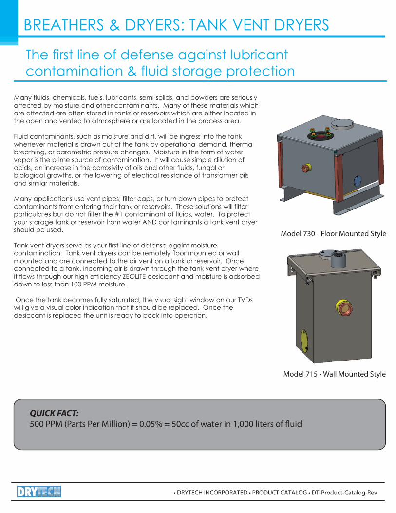
Model 730 - Floor Mounted Style
BREATHERS & DRYERS: TANK VENT DRYERS
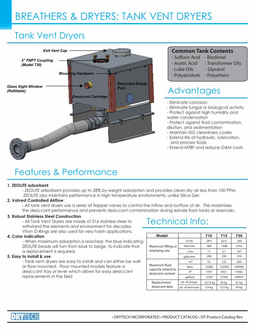
Tank Vent DryersCommon Tank Contents- Sulfuric Acid - Biodiesel- Acetic Acid - Transformer Oils- Lube Oils - Glycerol- Polyalcohols - Polyethers
Features & Performance
Advantages- Eliminate corrosion- Eliminate fungal or biological activity- Protect against high humidity and water condensation- Protect against fluid contamination, dilution, and sedimentation- Maintain ISO cleanliness codes- Extend life of hydraulic, lubrication, and process fluids- Extend MTBF and reduce O&M costs
Glass Sight Window(Refillable)
3” FNPT Coupling(Model 730)
Desiccant Cartridge
3. Robust Stainless Steel Construction - All Tank Vent Dryers are made of 316 stainless steel to withstand the elements and environment for decades. Viton O-Rings are also used for very harsh applications.4. Color Indication - When maximum adsorption is reached, the blue indicating ZEOLITE beads will turn from blue to beige, to indicate that a replacement is required.5. Easy to install & use - Tank vent dryers are easy to install and can either be wall or floor mounted. Floor mounted models feature a desiccant tray or lever which allows for easy desiccant replacements in the field
1. ZEOLITE adsorbent - ZEOLITE adsorbent provides up to 28% by weight adsorption and provides clean dry air less than 100 PPM. ZEOLITE also maintains performance in high temperature environments, unlike Silica Gel.2. Valved Controlled Airflow - All tank vent dryers use a series of flapper valves to control the inflow and outflow of air. This maximizes the desiccant performance and prevents desiccant contamination during exhale from tanks or reservoirs.
Desiccant Empty Port
Mounting Hardware
Exit Vent Cap
Technical Info:Model 710 715 730
m3/hr
liter/min
c.f.m.
galls/min
m3
liters
ft3
gallons
wt. of charge
wt. of desiccant
28.9
480
17
206
55
55000
1975
12297
10.75 kg
5.6 kg
62.9
1048
37
230
125
125000
4431
27593
20 kg
12.5 kg
250
4163
147
916
500
500000
17658
109972
67 kg
50 kg
Maximum filling oremptying rate
Maximum fluidcapacity related todesiccant content
Replacementdesiccant data
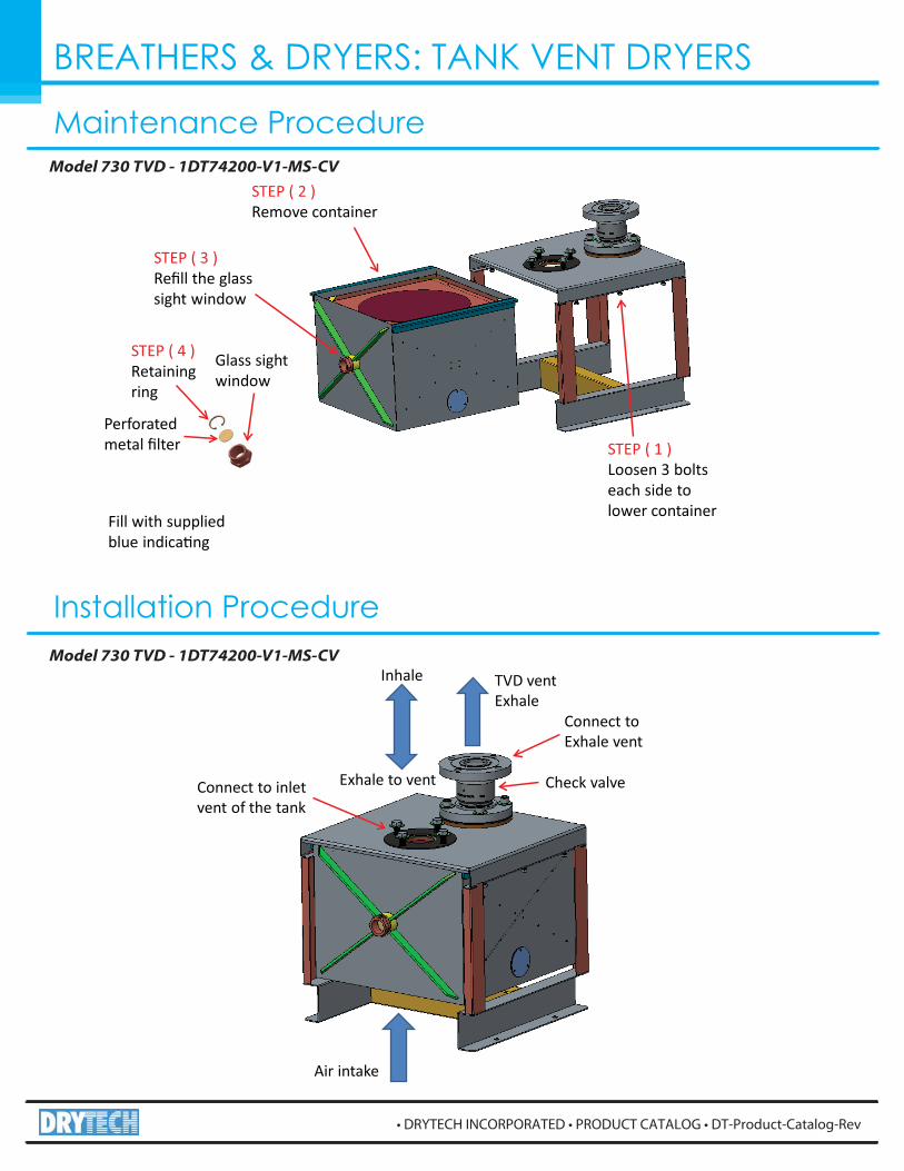
Air intake
Connect to inletvent of the tank
Inhale TVD ventExhale
Check valveExhale to vent
Connect toExhale vent
STEP ( 1 )Loosen 3 boltseach side tolower container
Perforatedmetal �lter
STEP ( 4 )Retainingring
Glass sightwindow
STEP ( 2 )Remove container
STEP ( 3 )Re�ll the glasssight window
Fill with suppliedblue indica�ng
Model 730 TVD - 1DT74200-V1-MS-CV
Model 730 TVD - 1DT74200-V1-MS-CV
Maintenance Procedure
Installation Procedure
BREATHERS & DRYERS: TANK VENT DRYERS
BREATHERS & DRYERS: TANK VENT DRYERS
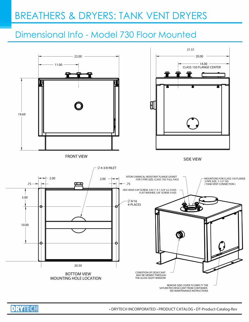
Dimensional Info - Model 730 Floor Mounted
MOUNTUNG FOR CLASS 150 FLANGE3 PIPE SIZE, 7-1/2" OD( TANK VENT CONNECTION )
VITON CHEMICAL-RESISTANT FLANGE GASKETFOR 3 PIPE SIZE, CLASS 150, FULL FACE
HEX HEAD CAP SCREW, 5/8-11 X 1-3/4" LG 316SSFLAT WASHER, 5/8" SCREW 316SS
CONDITION OF DESICCANTMAY BE VIEWED THROUGH
THE GLASS SIGHT WINDOW
REMOVE SIDE COVER TO EMPLTY THESATURATED DESICCANT FROM CONTAINER.
SEE MAINTENANCE INSTRUCTIONS
22.00
19.69
20.00
21.51
10.00
5.00
20.50
2.00
.75.752.00
9/164-PLACES
14.00CLASS 150 FLANGE CENTER
11.00
4-3/8 INLET
SIDE VIEW
BOTTOM VIEWMOUNTING HOLE LOCATION
FRONT VIEW
BREATHERS & DRYERS: TANK VENT DRYERS
How do they work?
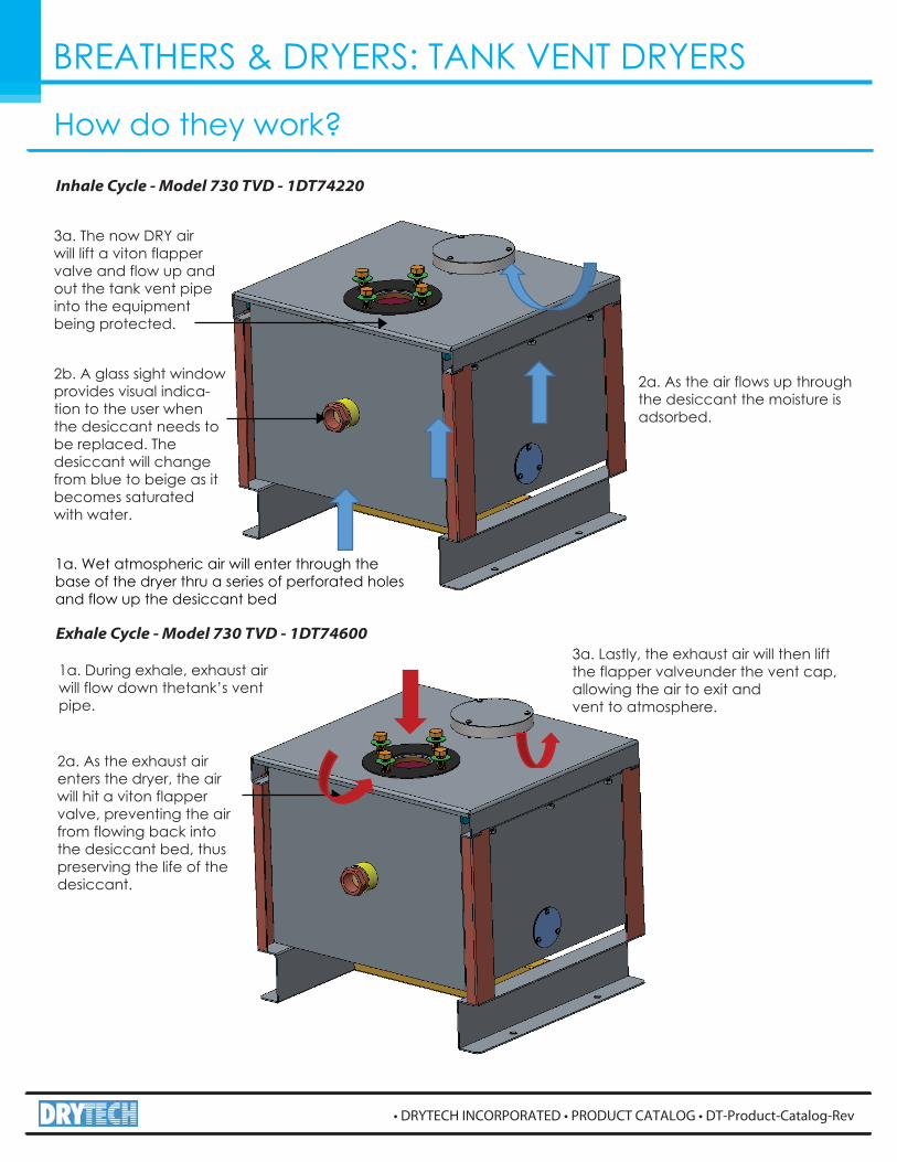
Inhale Cycle - Model 730 TVD - 1DT74220
Exhale Cycle - Model 730 TVD - 1DT74600
1a. Wet atmospheric air will enter through thebase of the dryer thru a series of perforated holesand flow up the desiccant bed
2b. A glass sight window provides visual indica-tion to the user when the desiccant needs to be replaced. The desiccant will change from blue to beige as it becomes saturated with water.
2a. As the air flows up through the desiccant the moisture is adsorbed.
3a. The now DRY air will lift a viton flapper valve and flow up and out the tank vent pipe into the equipment being protected.
1a. During exhale, exhaust air will flow down thetank’s vent pipe.
2a. As the exhaust air enters the dryer, the airwill hit a viton flapper valve, preventing the air from flowing back into the desiccant bed, thus preserving the life of the desiccant.
3a. Lastly, the exhaust air will then lift the flapper valveunder the vent cap, allowing the air to exit andvent to atmosphere.
BREATHERS & DRYERS: TANK VENT DRYERS
Applications Transformer Breathers Applications
Tank Vent Dryers Applications Breather Desiccators Applications
How do they work?
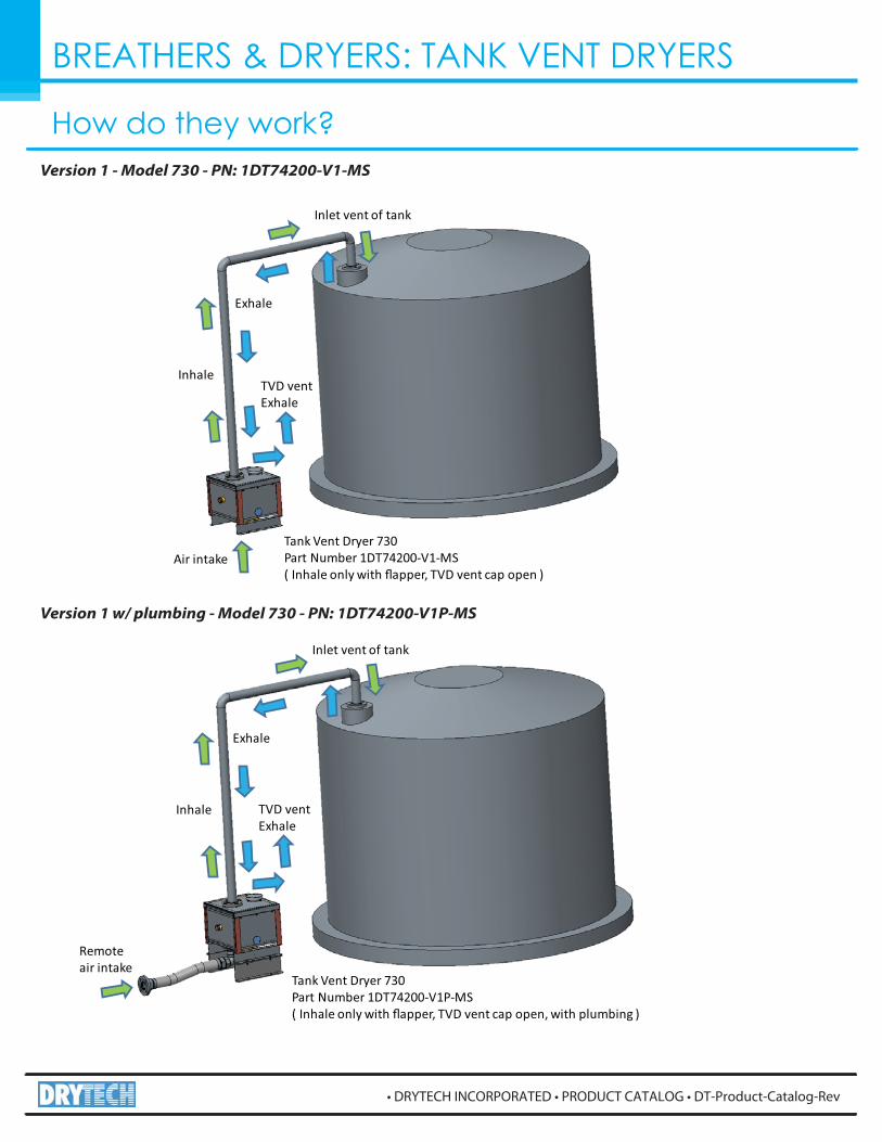
Air intake
Inhale
Exhale
TVD ventExhale
Tank Vent Dryer 730Part Number 1DT74200-V1-MS( Inhale only with �apper, TVD vent cap open )
Inlet vent of tank
Remoteair intake
Inhale
Exhale
TVD ventExhale
Tank Vent Dryer 730Part Number 1DT74200-V1P-MS( Inhale only with �apper, TVD vent cap open, with plumbing )
Inlet vent of tank
Version 1 - Model 730 - PN: 1DT74200-V1-MS
Version 1 w/ plumbing - Model 730 - PN: 1DT74200-V1P-MS
BREATHERS & DRYERS: TANK VENT DRYERS
How do they work?
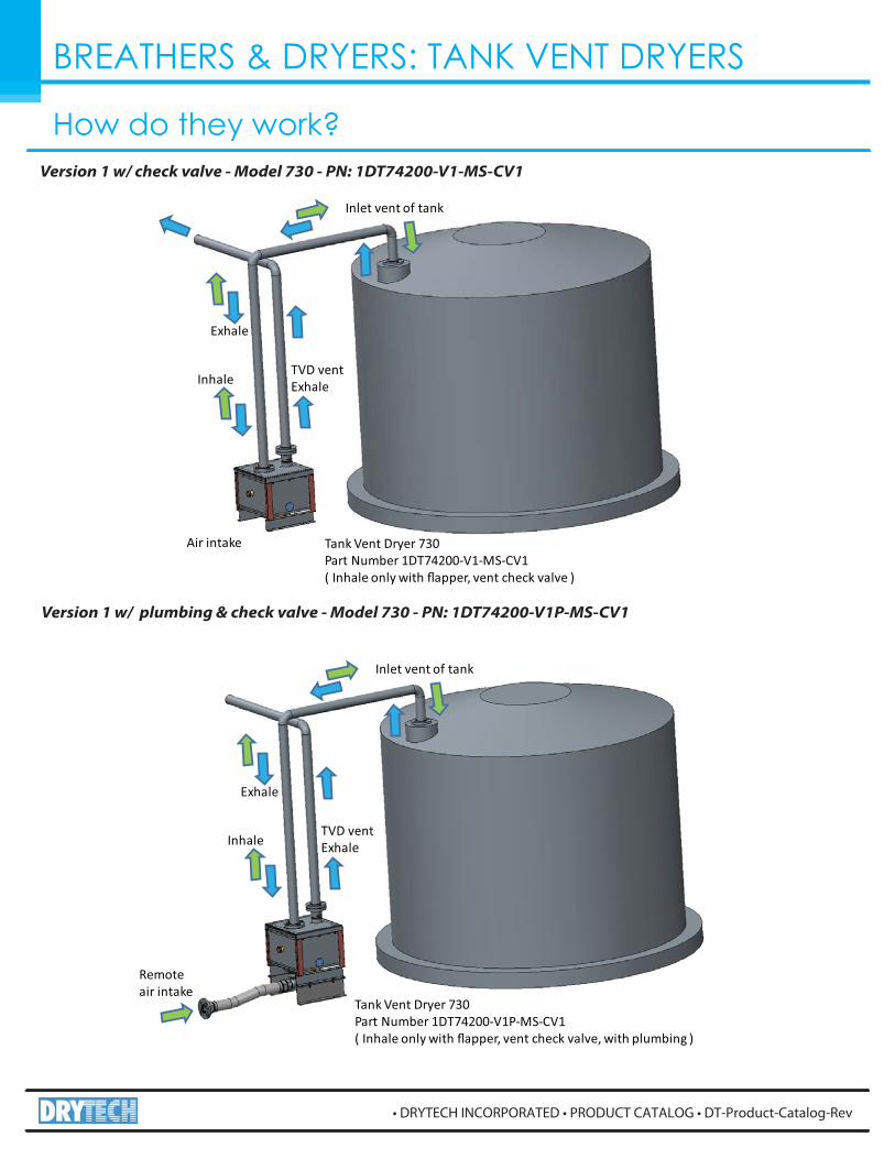
Air intake
Inhale
Exhale
TVD ventExhale
Tank Vent Dryer 730Part Number 1DT74200-V1-MS-CV1( Inhale only with �apper, vent check valve )
Inlet vent of tank
Remoteair intake
Inhale
Exhale
TVD ventExhale
Tank Vent Dryer 730Part Number 1DT74200-V1P-MS-CV1( Inhale only with �apper, vent check valve, with plumbing )
Inlet vent of tank
Version 1 w/ check valve - Model 730 - PN: 1DT74200-V1-MS-CV1
Version 1 w/ plumbing & check valve - Model 730 - PN: 1DT74200-V1P-MS-CV1
BREATHERS & DRYERS: TANK VENT DRYERS
How do they work?
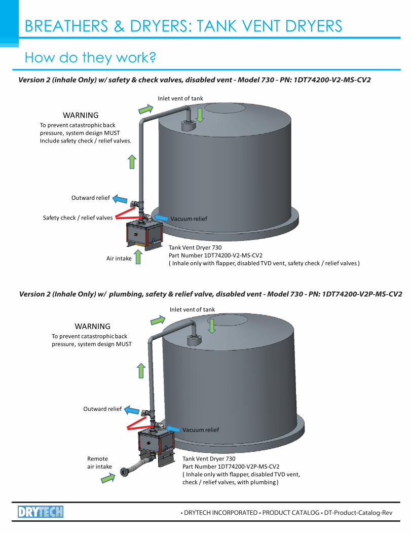
Tank Vent Dryer 730Part Number 1DT74200-V2-MS-CV2( Inhale only with �apper, disabled TVD vent, safety check / relief valves )
Outward relief
Air intake
Inlet vent of tank
Vacuum reliefSafety check / relief valves
WARNINGTo prevent catastrophic backpressure, system design MUSTInclude safety check / relief valves.
Tank Vent Dryer 730Part Number 1DT74200-V2P-MS-CV2( Inhale only with �apper, disabled TVD vent,check / relief valves, with plumbing )
Outward relief
Remoteair intake
Inlet vent of tank
Vacuum relief
WARNINGTo prevent catastrophic backpressure, system design MUST
Version 2 (inhale Only) w/ safety & check valves, disabled vent - Model 730 - PN: 1DT74200-V2-MS-CV2
Version 2 (Inhale Only) w/ plumbing, safety & relief valve, disabled vent - Model 730 - PN: 1DT74200-V2P-MS-CV2
BREATHERS & DRYERS: TANK VENT DRYERS
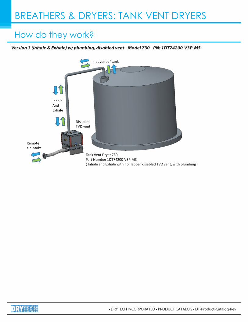
How do they work?
Remoteair intake
InhaleAndExhale
DisabledTVD vent
Tank Vent Dryer 730Part Number 1DT74200-V3P-MS( Inhale and Exhale with no �apper, disabled TVD vent, with plumbing )
Inlet vent of tank
Version 3 (inhale & Exhale) w/ plumbing, disabled vent - Model 730 - PN: 1DT74200-V3P-MS
BREATHERS & DRYERS: TANK VENT DRYERS
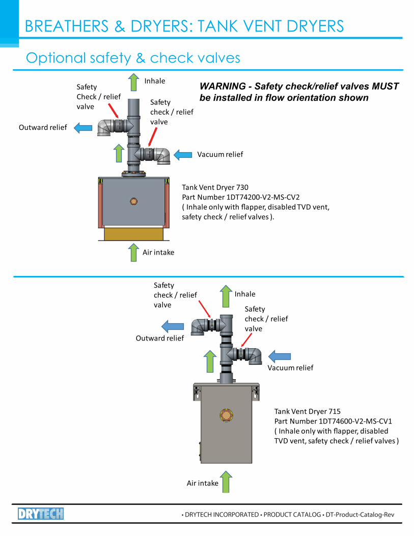
Optional safety & check valves
Outward relief
Vacuum relief
SafetyCheck / reliefvalve Safety
check / reliefvalve
Air intake
Inhale
Tank Vent Dryer 730Part Number 1DT74200-V2-MS-CV2( Inhale only with �apper, disabled TVD vent,safety check / relief valves ).
Inhale
Air intake
Vacuum relief
Outward relief
Safetycheck / reliefvalve Safety
check / reliefvalve
Tank Vent Dryer 715Part Number 1DT74600-V2-MS-CV1( Inhale only with �apper, disabledTVD vent, safety check / relief valves )
WARNING - Safety check/relief valves MUST be installed in flow orientation shown
BREATHERS & DRYERS: TANK VENT DRYERS
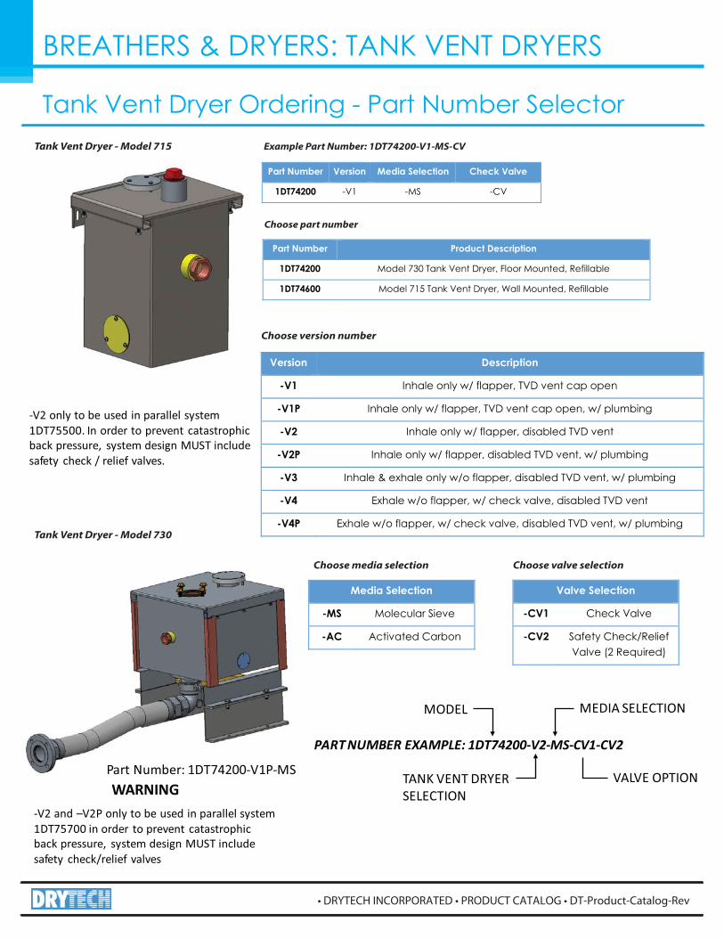
Tank Vent Dryer Ordering - Part Number Selector
Part Number: 1DT74200-V1P-MS
PART NUMBER EXAMPLE: 1DT74200-V2-MS-CV1-CV2
MODEL MEDIA SELECTION
TANK VENT DRYERSELECTION
VALVE OPTION
-V2 and –V2P only to be used in parallel system1DT75700 in order to prevent catastrophicback pressure, system design MUST includesafety check/relief valves
WARNING
Version Description
-V1 Inhale only w/ flapper, TVD vent cap open
-V1P Inhale only w/ flapper, TVD vent cap open, w/ plumbing
-V2 Inhale only w/ flapper, disabled TVD vent
-V2P Inhale only w/ flapper, disabled TVD vent, w/ plumbing
-V3 Inhale & exhale only w/o flapper, disabled TVD vent, w/ plumbing
-V4 Exhale w/o flapper, w/ check valve, disabled TVD vent
-V4P Exhale w/o flapper, w/ check valve, disabled TVD vent, w/ plumbing
Media Selection
-MS Molecular Sieve
-AC Activated Carbon
Choose version number
Choose media selection
-V2 only to be used in parallel system1DT75500. In order to prevent catastrophicback pressure, system design MUST includesafety check / relief valves.
Valve Selection
-CV1 Check Valve
-CV2 Safety Check/Relief Valve (2 Required)
Choose valve selection
Tank Vent Dryer - Model 715
Tank Vent Dryer - Model 730
Example Part Number: 1DT74200-V1-MS-CV
Part Number Version Media Selection Check Valve
1DT74200 -V1 -MS -CV
Part Number Product Description
1DT74200 Model 730 Tank Vent Dryer, Floor Mounted, Refillable
1DT74600 Model 715 Tank Vent Dryer, Wall Mounted, Refillable
Choose part number


