

GEAR '1.OOl'HING
by
w. Nageli
"MAAG Toothing"
2 Deformations of toothing and gear rotors.
Profile and longitudinal modifications of
involute tooth flanks
2.1 Tooth load distribution along the
path of contact in the transverse
section
2.2 Uniform tooth load distribution
along the face width
3 Calculation of load capacity
4 Example of toothing of a high speed
turbo gear
5 Final remarks
6 Figs. 1 to 11

- 2 - MAAIi ZURICH
GEAR 'IOOI'HING
In gear driven industrial plants the toothing occupies very little space.
However, the successful operation of the plants and consequently the pro
fits therefrom highly depend on this very important space. Successful
plant operation depends on the optimum and most reliable transmission of
the torque between the two gear rotors by the tooth flanks.
In this brief lecture we will concentrate on a few important topics con
cerning the involute gear toothing.
"MAAG Toothing"
"MAAG TOOthing" is related to the tooth geometry and especially to the
addendum modification (long addendum, addendum modification coefficient,
rack shift) which was invented by Max Maag.
Two gears with involute tooth flanks have correct meshing conditions on
any center distance if they have an identical base pitch and an identical
base helix angle. The operating pitch circle of each gear does not have
to be identical with the generating pitch circle (reference circle).
"MAAG Toothing" practically always has a center distance greater than
half the s um of the reference diameters; in other words, the sum of the
addendum modification coefficients of pinion and gear is always posi
tive.
Figure 1
This represents the principle of the addendum modification x·m
(x = addendum modification coefficient, m = module = 1/DP).
What are the advantages of this principle?
The amount of shifting of the basic rack simply defines nothing else than
a certain part of the involute as active tooth flank. Without an addendum
modification , the active flank may be too close to the base circle and
the radius of curvature becomes very small, resulting in a high contact
stress (pitting). Besides this, the relative sliding between the tooth

- 3 - MAAG Z URICH
flanks of pinion and gear is greater and, consequently, the danger of
scoring is increased.
with a favourable addendum modification these disadvantages can be avoid
ed and an optimum tooth form with regard to tooth bending strength may,
furthermore, be obtained (especially the fillet curve). The maximum pos
sible addendum modification is determined by the minimum allowable tooth
thickness at the tip.
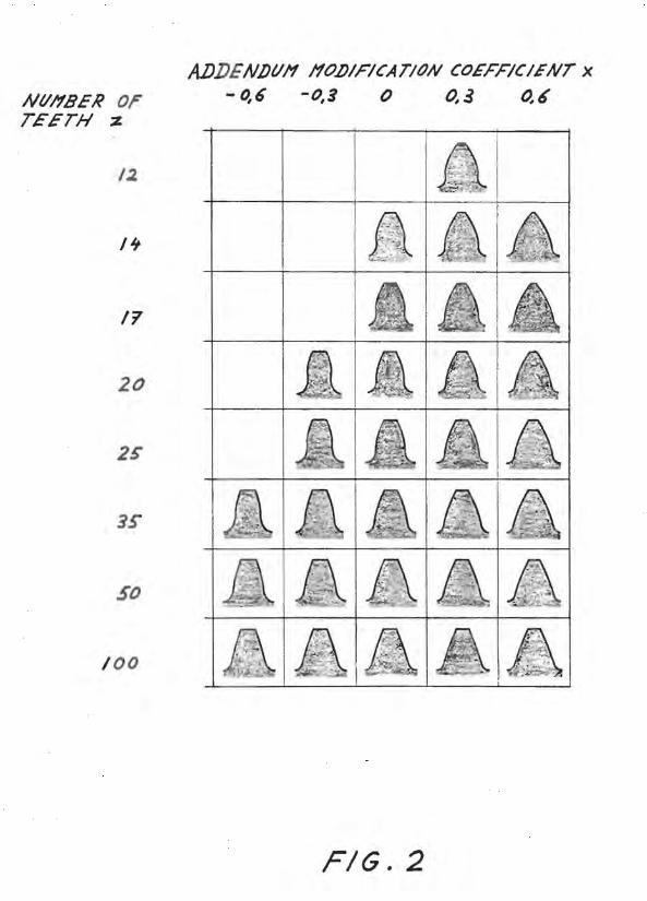
Figure 2
This represents tooth form as a function of the number of teeth z, versus
addendum modification coefficient x.
Figure 3
This approximate equation, which is very simple canpared with the exact
involute equation indicates the relation between center distance am normal module, number of teeth in pinion and gear, hel ix angle, sum of
addendum mod ification coefficients.
The "MAAG Module Table" contains very fine steps. Because of this, a
solution can always be found for this equation for a given center dis
tance, a desired opt imum module (with regard to bending and scoring), a
sum of (Xl + x2), a hel ix angle and a desired gear ratio z2/z1.
MAAG, consequently, applies this module table am there are no manu
facturing difficulties , because low-cost rack-type cutters are used in
stead of expensive hobs. Tooth grinding machines am the tooth measuring
machines do not depend on the module.
This was the "MAAG Toothing" at the time of Max MAAG.
The difficult problem still remained, however, of how to split the sum of
the addendum modification coefficients into Xl for the pinion am x2
for the gear. 1958, Robert Wydler from MAAG published a calculating me
thod based on non-dimensional contact parameters, to determine in each
case exact values of the addendum modification coefficients of the pinion
x1 and of the gear x2.

- 4 - MAAG ZURICH
In 1972, he subsequently developed a flash temperature calculating method
as a scoring criterion, which is also influenced by the addendum modifi
cation coefficients.
These methods allow for an optimum balancing of the gear meshing condi
tions, such as sliding versus rolling between the tooth flanks and also
for the flash temperatures of pinion and gear.
In canbination with profile and longitudinal modifications of the tooth
flanks this is now the actual "MAAG Toothing", which is a systematical
lay-out method, strictly applied day by day for any type of gear and is
related to more than 20 years of sucessfull and reliable gear manu
facturing.
2 Deformations of tooth ing and gear rotors
Profile and longitudinal modifications of involute tooth flanks
As already mentioned the most reliable transmission of the torque between
the two gear rotors by the tooth flanks is of the greatest importance.
Therefore, the mechanical deformations of the teeth and rotors and the
thermal deformations of the rotors due to non-uniform temperature distri
bution have to be canpensated for, by modifying the actual ground tooth
flanks and thereby deviating from the mathematical true involute form, in
order to obtain a satisfactory full load tooth bearing pattern.
2.1 Tooth load distribution along the path of contact in the transverse
section
In order to prevent engagement shocks, due to tooth bending deformations,
and to obtain a "trapeziform" tooth load distribution along the path of
contact in the transverse section, profile modifications are always ap
plied by means of tip and root reliefs on the pinion. The shape and
magnitude of these modifications have to be carefully determined, in
connection with the calculated tooth stiffness of the gear mesh, and with
accumlated results in the field.

- 5 - MAAG ZURICH
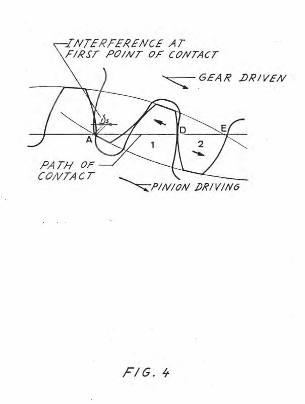
Figure 4
This shows the interference at the first point of contact (point A) of
a true involute toothing without profile modifications. This interference
is due to the bending deformations of the teeth number 1 and 2 being in
contact to each other at point D. The resulting shock is a source of
noise and it may decrease the strength of the toothing in all its
aspects, including the oil film on the tooth flanks.
Figure 5
This shows the profile modification (profile diagram) of the pinion and
the "trapeziform" tooth load distribution obtained along the path of
contact without engagement shock.
2.2 Uniform t ooth load distribution alOng the face width
In order to obtain a uniform tooth load distribution along the face
width, a longitudinal IOOdification on the pinion is always applied to
compensate for the bend ing, torsional and thermal deformations of the
gear mesh.
Figure 6
This represents the bending and torsional deformations of the pinion
separately and combined , as well as the resulting longitudinal modifi- ·
cation.
For gears with pitch line velocities above approx. 80 m/s (16000 ft/min)
additional thermal deformations of pinion and gear have to be considered.
These deformations originate fran heat due to the power loss in the
meshing zone by the displacement of the air/oil mixture out of the tooth
spaces.
In a helical gear, this displacement rroves along the face width (screw
pump effect) from the cooler side to the warmer exit side. The side faces
of the rotors, especially the larger one of the gear rotors have a cool
ing effect. The resulting thermal tooth flank deformation of pinion and

- 6 - MAAG ZURIC H
gear has an asymmetrical barrel shape. Measured along the face width from
the cooler side to the warmer side, the base tangent length would in
crease to a certain peak value and decreases toward the warmer side to a
value which is still larger than the one on the cooler side.
If these thermal deformations are not compensated for, they cause a high
local overload between the tooth flanks, seriously endangering the safe
operation of the gear. To obtain an equal tooth load distribution along
the face width, the pinion tooth flanks are provided with a conical/co
cave longitudinal modif ication.
Very extensive tests performed by MAAG with pitch line velocities up to
200 mls (39000 ft/min), using thermocouples installed in the gear rotors,
cleary indicated that even with all kinds of asymmetrical oil injections
into the gear mesh or gear housing, it is practically tmpossible to ob
tain a uniform temperature distribution in pinion and gear, which would
allow for the omission of this conical/concave longitudinal modifica
tion.
The total longitudinal modification is the superposition of the modifi
cation for the mechanical deformations and the modifi.cation for the ther
mal deformations. The typical shape of such a longitudinal modification
will be shown together with the data of an example of a high speed turbo
gear, Fig . 10.
Working flanks provided with such longitudinal modifications cannot be
used to align a gear, because the blue tooth bearing pattern is much too
short. Therefore, the non-working flanks of pinion and gear are ground
absolutely parallel and are used as a basis for the correct alignment of
the gear.
3 Calculation of load capacity
Many different calculating methods are applied around the world to calcu
late the load capacity of the gear toothing. Some of these are very
simple ' and others are very detailed, for example:
- 7 -
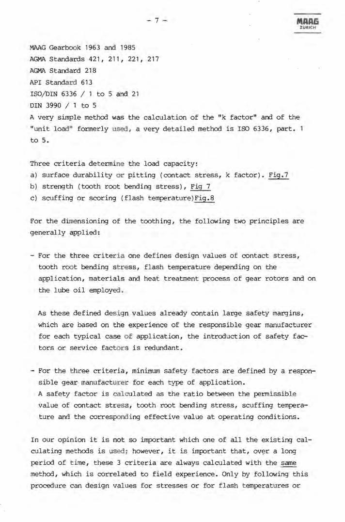
MMG Gearbook 1963 and 1985
AGMA Standards 421,211,221,217
AGMA Standard 218
API Standard 613
ISO/DIN 6336 / 1 to 5 and 21
DIN 3990 / 1 to 5
MAAG ZURICH
A very simple method was the calculation of the "k factor" and of the
"unit load" formerly used, a very detailed method is ISO 6336, part. 1
to 5.
Three criteria determine the load capacity:
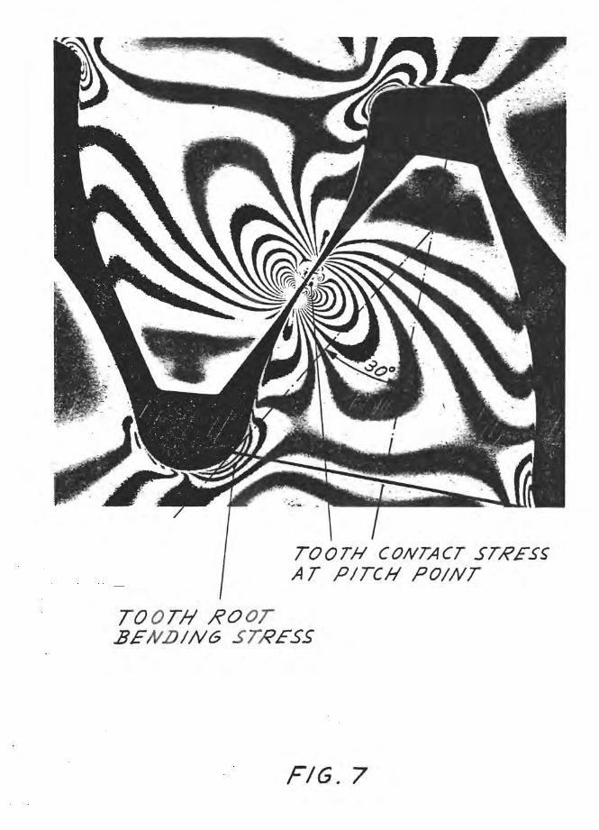
a) surface durability or pitting (contact stress, k factor). Fig.7
b) strength (tooth root bending stress), Fig 7
c) scuffing or scoring (flash temperature)Fig.8
For the dimensioning of the toothing, the following two principles are
generally applied:
- For the three criteria one defines design values of contact stress,
tooth root bending s tress, flash temperature depending on the
application, materials and heat treatment process of gear rotors and on
the lube oil employed.
As these defined design values already contain large safety margins,
which are based on the experience of the responsible gear manufacturer
for each typical case of application, the introduction of safety fac
tors or service factors is redundant.
For the three criteria, minimum safety factors are defined by a respon
sible gear manufacturer for each type of application.
A safety factor is calculated as the ratio between the permissible
value of contact stress, tooth root bending stress, scuffing tempera
ture and the corresponding effective value at operating conditions.
In our opinion it is not so important which one of all the existing cal
culating methods is used; however, it is important that, ov~r a long
period of time, these 3 criteria are always calculated with the same
method, which is correlated to field experience. Only by following this
procedure can design values for stresses or for flash temperatures or
- 8 - MAAG ZURICH
corresponding safety f actors or service factors be developed for the
satisfactory layout of a toothing for each typical case of application.
When one wants to switch from a present, simpler method to a new, de
tailed method, both methods must be applied in parallel over at least
the next 5 years, so as to correlate them to actual experience and to be
able to determine adequate safety factors for this new method.
A MAAG t oothing always complies with the MAAG Gearbook 1963 and 1985 and
with the MAAG flash temperature criterion of 1972. The corresponding
allowable design values for contact stress, bending stress and flash
temperature are related to the past 20 years of successful gear manufac
turing. They are conservative and contain a large safety margin, but they
do not necessarily overs ize a gear.
If requested, a MAAG toothing additionally complies with the specified
service f actor of the corresponding standard, for example AGMA Standard
421.06 or API Standard 613.
In general the MAAG and AGMA philosophy go nicely together as long as the
specified AGMA service factor is not unreasonably high (for example grea
ter than 1.5).
The same value for the service factor using API Standard 613 results in a
toothing wi th increased dimensions (face width, center distance).
For medium pitch line velocities up to 130 mls (25000 ft/min) this over
sizing of t he gear may not do any harm, although it is not required for a
MAAG toothing. At high pitch line velocities above 130 mls (25000 ft/min)
an oversized toothing would only produce considerably more power loss,
larger mechanical deflections and thermal deformations of the tooth
flanks, and, as a result, a less safe torque transmission between pinion
and gear i nstead of add i tional safety. The authors of API Standard 613,
therefore, included deviation paragraph 2.2.5, so the gear manufacturer
is obliged to inform his customers about these conditions.
MAAG also applies the new detailed standards ISO/DIS 6336/1 to 5, which
are published in the MAAG Gearbook 1985, a method here called "IS0-MAAG",
which represents the application standard for all MAAG gears .
- 9 - MAAG ZURICH
The intention is to establish a relationship between the MAAG method of
MAAG Gearbook 1963, presently applied, and the new methods with regard to
the required safety f actors.
We already noticed that the minimum safety factors (1.3 for contact
stress and 1.6 for bending stress) as indicated in the application stan
dard DIN 3990 part 21 for high speed gears and gears of similar require
ments are much too low for a gear design of high reliability.
Sufficient experience does not exist yet using the "flash temperature
criterion" nor with the "integral temperature criterion". Both criteria
are only val id for pi tch line velocities up to 80 m/s (16000 ft/min).
Therefore, at the present time, MAAG applies the MAAG flash temperature
method of 1972, which is well proved for high speed turbo gears and gears
of similar requirements with pitch line velocities well above 80 m/s
(16000 ft/min).
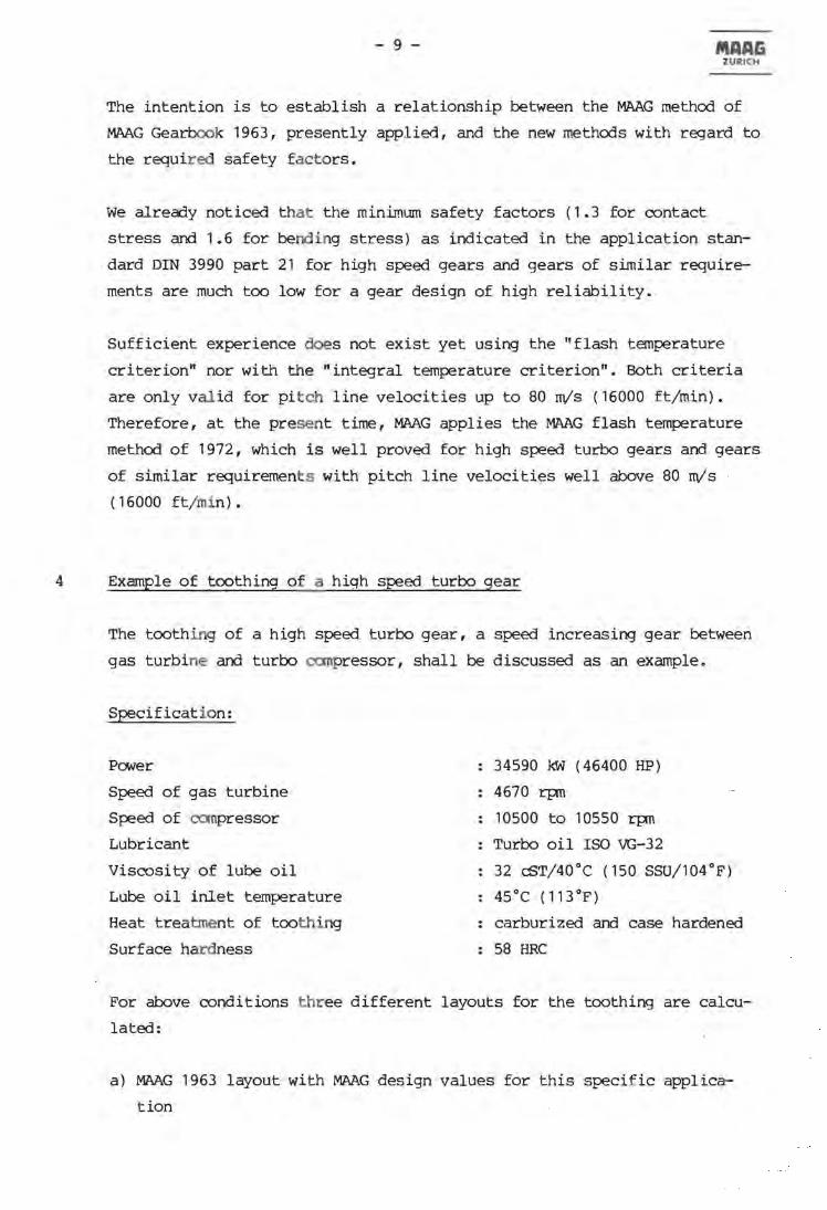
4 Example of toothing of a hiqh speed turbo gear
The tooth ing of a high speed turbo gear, a speed increasing gear between
gas turbine and turbo compressor, shall be discussed as an example.
Specification:
Power
Speed of gas turbine
Speed of compressor
Lubricant
Viscosity of lube oil
Lube oil inlet temperature
Heat treatment of toothing
Surface hardness
34590 kW (46400 HP)
4670 rpn
10500 to 10550 rpn
Turbo oil ISO VG-32
32 CST/40°C (150 SSU/104°p)
45°C (113°p)
carburized and case hardened
58 HRC
Por above conditions three different layouts for the toothing are calcu
lated:
a) MAAG 1963 layout with MAAG design values for this specific applica
tion

- 10 - MAAG ZURICH
b) AGMA 421.06 layout, with Service Factor = 1.6
c) API 613 layout, with Service Factor = 1.6
MAAG gear type GB-50, with a center distance of 500 mm (19.685 inch) is
applied for the three layouts, MAAG, AGMA, API, resulting in a high pitch
line velocity of 169.4 m/s (33350 ft/min).
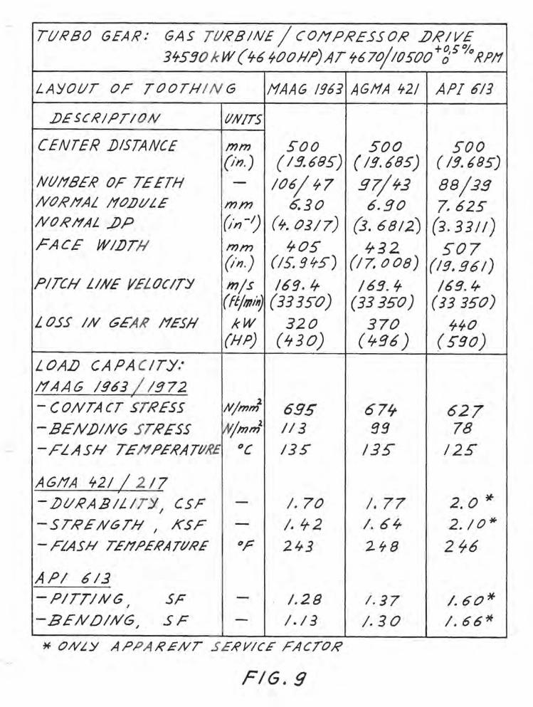
Figures 9, 10, 11
In these figures, characteristic data of these layouts are put together
for comparison. Some points of special interest shall be explained here:
4. 1 Geanetry of toothing
Each layout has an optimum combination, regarding number of teeth, normal
module (normal diametral pitch), helix angle, center distance, addendum
modification coefficients and actual speeds.
4.2 Face width
MAAG
405 mm
(15.945 in)
432 mm
(17.008 in)
API
507 mm
(19.961 in)
MAAG requires the smallest face width and the corresponding ratios of
face width to pitch d iameter are:
MAAG API
1.32 1.41 1.65
The ratio 1.65 of the API layout is too large, but a consequent increase
of the center distance would raise the pitch line velocity above a desi
red design limit.

- 11 - MAAG ZURICH
4.3 Load capaci ty: MAAG, AGMA , API
It can be clearly seen by comparing the acutal service factors, that MAAG
and AGMA apply similar design philosophy.
The unnecessarily oversized API layout does not correspond with MAAG or
AGMA.
In regard to the scoring criterion (flash temperature) the design values
of MAAG and AGMA standard 217.01 are practically reached.
4.4 Power loss in gear mesh
MAAG
320 kW
(430 HP)
370 kW
(496 HP)
API
440 kW
(590 HP)
The comparison of the three layouts clearly shows that MAAG, with the
smallest face width and the smallest module (largest diametral pitch),
has the smallest power loss in the toothing.
The higher the power l oss is, the higher the heat that has to be taken
out of the gearbox by the lube oil and the larger the thermal deforma
tions of the gear rotors. The combination of the highest power loss with
the largest face width (API layout) would only create an uncertainty in
obtaining a uniform t ooth load distribution along the face width, even
with a longitudinal modification.
Instead of having a gear with increased safety, the gear would actually
have a reduced reliability.
- 12 - MAAIi ZURICH
4.5 Mechanical and thermal deformations, longitudinal modifications
Figure 10
This illustrates the above mentioned problems in more detail.
The mechanical deformation of the pinion, due to bending and torsion, the
combined thermal deformation of pinion and gear and the resulting total
deformat ion between the tooth flanks of pinion and gear are indicated for
the MAAG layout. The thermal deformation is of much higher magnitude than
the mechanical deformation.
The corresponding longitudinal modifications are drawn to scale for the
MAAG layout, the AGMA layout and the API layout, at the bottom of Fig.
10.
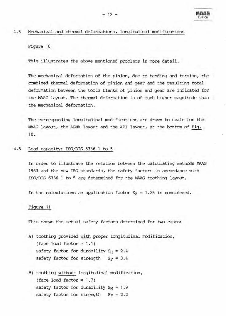
4.6 Load capacity: ISOjDIS 6336 1 to 5
In order to illustrate the relation between the calculating methods MAAG
1963 and the new ISO s tandards, the safety factors in accordance with
ISO/DIS 6336 1 to 5 are determined for the MAAG toothing layout.
In the calculations an application factor KA = 1.25 is considered.
Figure 11
This shows the actual safety factors determined for two cases:
A) toothing provided with proper longitudinal modification,
(face load factor = 1.1)
safety factor for durability SH = 2.4
safety factor for strength SF = 3.4
B) toothing without l ong itudinal modification,
(face load factor = 1.7) ·
safety factor for durability SH = 1.9
safety factor for strength SF = 2.2

- 13 - MAA& ZURICH
The striking difference between the safety factors of case A) and B)
makes it obvious that proper longitudinal modifications must be applied
by all means !
5 Final Remarks
To conclude this brief lecture about gear toothing, let me state the
following:
Despite all the applied calculating methods, standards, the help of c0m
puters and numerical controlled machine tools, the gear toothing still
remains a work of art. Satisfactory results essentially depend on the
know-how of the people involved and above all on their will to do their
best every day. This is mainly true for the staff of the heat treatment,
gear cutting, gear grinding and gear inspection departments, but is also
true for the assembly shop and for those out in the field.
Gears from different gear manufacturers may follow identical safety or
service factors, determined in accordance with official standards to
calculate load capacity, but their reliability can nevertheless turn out
to be totally different - due to the disparity in the quality of
workmanship. Even if a gear is properly designed and manufactured, it
might still suffer damage , if it is put in service without the correct
alignment.
Accordingly, every possible effort has to be made in relation to the gear
toothing. One has to see to it that foreseen savings will not turn out to
endanger the design philosophy or be responsible for lowering the accura
cy. This could be disastrous in regard to the reliability of the plant
and thus cause loss of production.
A gear customer is well advised to select a gear manufacturer that he can
trust as much as he trusts his own dentist.
Gentlemen, MAAG hopes that you always select the best "dentist"!
WN/ff
13.03.87

MAAIi ZURICH
REFERENCE CIRCLE
REFERENCE CIRCLE
TOO l'1ucH AIJDENJ)UI1 /'fOJ)/F/CAT/()N
REFERENCE CIRCLE
FIG, /
NtlI'IBE~ or TEETH %
12
1'1
11
20
2S
35'
50
1 00
AJ)])ENf)I//1 IfOJ)IFICATltJ# COEFFICIENT x -0,6 -0,3 0 0,.$ 0,6
A-··· .$. _,--" &--.:-
- , .... .,...-; ... 1 P
FIG. 2

Q . - CENTER DISTANCE
mn - NOR tfAL /10IJULE =}1;p ZI - Nt/I1EER OF TEETH IN PINION
Z2 - Nt/I1EER OF TEETH IN GEAR
;3 - HELIX A NGLE
X, - AJ)])ENJ)LlI1 !1(}f)IFICATION COEFFICIENT OF PIIVION
X2 - AJ)J)ENJ)lJh f!OJ)IFICATIOAl COEFFICIENT OF GEAR
(X, +X2) - 0-;- 0. 3 + 0.8 +1.3
FIG . .J
:TNTERFEI<ENCE AT FIRST POINT OF CONTACT
PATH OF CON TACT
... ~ GEAR .1J/?IVEN
~PINION J)/?IVIN6
FIG. ~

PROF'II.E j)IAGRAI1 OF PIN/ON W/TH /"/OJ)IFICATION
100% LOA])
TRAPEZIFOR/1 TOOTH LOA.P lJISTRIBVTION AJ.ONG PATH OF CONTACT
, 0% LOA})
TIP /?ELIEF
B 0
])RIVEN
/?OOT R£I.I£F---.J
~ PINION .JJRIVING
FIG. S

BEN])IN6
TORS/ON
BENJ)ING + TORSION
L ON61TUlJIN AL 110.DIFICATION (.lJIAGRA11 )
~ .•......... tv.\.t " .AA""V; ........ ; .. ;o
TO/?GUE
iJ;o P
FIG. 6
TOOTH CONTACT STRESS AT PITCH POINT
TO OTH ,RooT BENLJING STRESS
FIG. 7
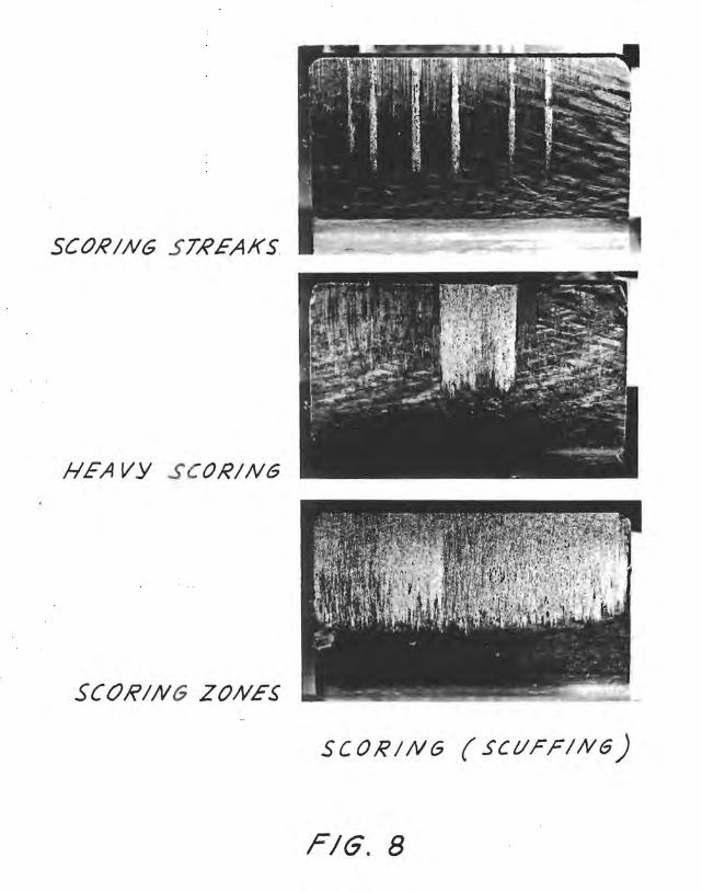
SCORING STREAKS
HEAVY SCORING
SCORING ZONES
SCORING (SCUFFING)
FIG. 8
TURBO GEAR: GAS TtJRBIN£ / COI1PRESSOR LJRIV£ 3'tS!JO k W ('t6 'tOOJlfJ)AT '16 7o/l()SOO +:;5''10 tfPI1
LAYOUT OF TOOTHIN G HAAG /963 AGffA "'2/ API 613
.IJESCRIPTION IIN/TS
CENTER j)/STANCE mm soo SOO SOO (il? ) ( 1!J.6BS) ( Ig. b85) ( 13.685)
NtJl1BER OF TEETH - 106/ It7 g7/ 'r3 88/.19 Nc:?RI1AL /10J)//LE mm 6.30 6.90 7.62S NORHAL ..f)P ~·n-!) (It. 0317) (3.6812) (3.33//) rACE WI.f)Th' rom 'rOS 'r32 S07
(in.) (IS.9"S) (17. 008) (Ig. 96/) PITCH LINE YELOCITY m/s /6g./r /6!J. 't /69. ¥
(ft/""~ (3335"0) (33350) (33350) LOSS IN GEAR tfESfI kW 320 370 'tirO
(HPj (it 30) (Lrq6) ( 5"90)
LOAlJ CAPA CITY:
I1AAG Ig63 / lg72 , - CONTACT STRESS N/mm
l 695 67ft 627
- BENJ)ING STRESS W/mm2 113 gg 78 -FLASH TEh PERATIJIfE °C 13S /3S /2S
AGI1A 't21 / 2 17 , - .l)//RA.BILITY, CSF - 1.70 1.77 2.0 if
-STRENGTH I KSF - I. 't2 I. 6 Lr 2.10* - FLASH TEI1.PERATI/RE Or 243 2't8 2 '16
API 613 -PITTING SF - 1.28 1.37 1.60* I
-BENOI;VG~ SF - I. 13 1.30 I. 66~
*' ONLY APPA RENT SERVICE FACTOR
FIG. 9

,----- . -. ---.
" I . I I
LONGITlIJ)INAL 110.DIFICATION G8-S0 /1AA~ I~~J G8-S0 A&I1A ¥llt)( SF"!. 6 _ 68 - so API IIJ SF" I.. .-.-
~
BENOING
TORSION
lJENj)ING + TORSION
FACF WIDTH
FIG. 10

TIJRBO GEAR: GAS TtlREINE I COIfPR£S50R .JJRIVE . 3't530 k W( 'tb400fl,Pj AT /r670/IOS32 1f,P11
CALCIJLATI()N OF LOAf} CAPACITY(LAYOIJT!1AAGIgIJ) ISO/f)IS 6336 / 1+ S
CASE A" WITH LONGITI/J)INAL I1Cl.lJIFICATION ,FAC£ LOAf) FACTOR J(H,Ij = 1.1 A /1f'LI{'ATI()N FACTOR XA = 1,2S
CASE .B: W/THOtJT LONGITtllJlNAL /10.J)IF/CATION FA CE L OA/J FA eTOR }(flj! = I. 7 A/1PLICATI()N FACTOR K,., = I. 2S
6HI' = 16/0
o HI/"" =_1...;;;.,..'S_2 O--+_-+-_~
SAFETY FACTORSH= 2.'1 1. 9
CASE:
o SURFACE .l)//I?AEILITY
IV/171m2
6FP = 987
SAFETY FACTOR SF = 3. ¥ 2.2
6FO = 201
CASE:
o BENlJING STRENGTH
Njmm2
FIG, I I


