
559 560
CARB
IDE
PILO
T PU
NCHE
S
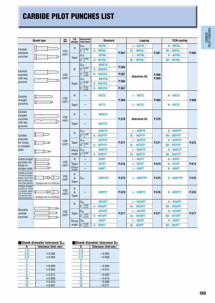
CARBIDE PILOT PUNCHES LIST
Shank type RTip
shapeShank diameter tolerance Standard Lapping TiCN coating
Carbide standard punches
V30 (HIP)
RDm5 WSTA□
P.561
L-WSTA□
P.561
H-WSTA□
P.563D+0.005
0 A-WSTA□ AL-WSTA□ AH-WSTA□
TaperDm5 WTPA□ L-WTPA□ H-WTPA□D+0.005
0 A-WTPA□ AL-WTPA□ AH-WTPA□
Carbide punches with key grooves
V30 (HIP)
R
Dm5 WKSTA□P.565
Alteration SC P.566 P.568
D+0.0050 A-WKSTA□
D-0.001-0.006 B-WKSTA□ P.567
Taper
Dm5 WKTPA□P.565
D+0.0050 A-WKTPA□
D-0.001-0.006 B-WKTPA□ P.567
Carbide straight punches
V30 (HIP)
R - WSTC
P.569
L-WSTC
P.569
H-WSTC
P.569
Taper - WTTC L-WTTC H-WTTC
Carbide straight punches with key grooves
V30 (HIP)
R - WKSTC
P.570 Alteration SC P.570
Taper - WKTTC
Carbide punches for fixing to stripper plate
V30 (HIP)
RDm5 WSPTP
P.571
L-WSPTP
P.571
H-WSPTP
P.572
D+0.0050 A-WSPTP AL-WSPTP AH-WSPTP
TaperDm5 WTPTP L-WTPTP H-WTPTP
D+0.0050 A-WTPTP AL-WTPTP AH-WTPTP
Sharp angle
Dm5 WAPTP L-WAPTP H-WAPTP
D+0.0050 A-WAPTP AL-WAPTP AH-WAPTP
Carbide straight punches for fixing to stripper plate
V30 (HIP)
R - WSPT
P.573
L-WSPT
P.573
H-WSPT
P.574Taper - WTPT L-WTPT H-WTPTSharp angle - WAPT L-WAPT H-WAPT
Carbide punches for fixing to stripper plates, tip R and taper combined type, minus head tolerance
V30 (HIP)
R &
TaperDm5 WSPTPF P.575 L-WSPTPF P.575 H-WSPTPF P.575
Carbide straight punches for fixing to stripper plates Tip R and taper combined type, minus head tolerance
V30 (HIP)
R &
Taper- WSPTF P.576 L-WSPTF P.576 H-WSPTF P.576
Movable carbide punches
V30 (HIP)
RDg6 WSUPT
P.577
L-WSUPT
P.577
H-WSUPT
P.577
D-0.005-0.010 A-WSUPT AL-WSUPT AH-WSUPT
TaperDg6 WTUPT L-WTUPT H-WTUPT
D-0.005-0.010 A-WTUPT AL-WTUPT AH-WTUPT
Sharp angle
Dg6 WUPT L-WUPT H-WUPT
D-0.005-0.010 A-WUPT AL-WUPT AH-WUPT
■Shank diameter tolerance Dm5
D Tolerance(Unit: mm)1.6
+0.006 +0.002
2.02.534
+0.009 +0.0045
68 +0.012
+0.0061013 +0.015
+0.00716
■Shank diameter tolerance Dg6
D Tolerance(Unit:mm)1.6
-0.002 -0.008
2.02.534
-0.004 -0.0125
68 -0.005
-0.0141013 -0.006
-0.01716
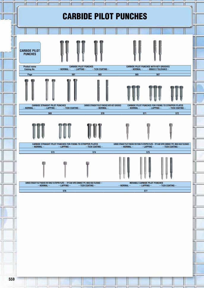
Product name CARBIDE PILOT PUNCHES CARBIDE PILOT PUNCHES WITH KEY GROOVESCatalog No. -NORMAL- -LAPPING- -TiCN COATING- -NORMAL- -MINUS D TOLERANCE-
Page 561 563 565 567
CARBIDE PILOT PUNCHES
CARBIDE STRAIGHT PILOT PUNCHES CARBIDE STRAIGHT PILOT PUNCHES WITH KEY GROOVES CARBIDE PILOT PUNCHES FOR FIXING TO STRIPPER PLATES-NORMAL- -LAPPING- -TiCN COATING- -NORMAL- -NORMAL- -LAPPING- -TiCN COATING-
569 570 571 572
CARBIDE STRAIGHT PILOT PUNCHES FOR FIXING TO STRIPPER PLATES CARBIDE STRAIGHT PILOT PUNCHES FOR FIXING TO STRIPPER PLATES -TIP R AND TAPER COMBINED TYPE, MINUS HEAD TOLERANCE--NORMAL- -LAPPING- -TiCN COATING- -NORMAL- -LAPPING- -TiCN COATING-
573 574 575
CARBIDE STRAIGHT PILOT PUNCHES FOR FIXING TO STRIPPER PLATES -TIP R AND TAPER COMBINED TYPE, MINUS HEAD TOLERANCE- MOVABLE CARBIDE PILOT PUNCHES-NORMAL- -LAPPING- -TiCN COATING- -NORMAL- -LAPPING- -TiCN COATING-
576 577
CARBIDE PILOT PUNCHES
○Enlarged view of circled part
○Enlarged view of circled part
559 560
CARB
IDE
PILO
T PU
NCHE
S
CARBIDE PILOT PUNCHES LIST
Shank type RTip
shapeShank diameter tolerance Standard Lapping TiCN coating
Carbide standard punches
V30 (HIP)
RDm5 WSTA□
P.561
L-WSTA□
P.561
H-WSTA□
P.563D+0.005
0 A-WSTA□ AL-WSTA□ AH-WSTA□
TaperDm5 WTPA□ L-WTPA□ H-WTPA□D+0.005
0 A-WTPA□ AL-WTPA□ AH-WTPA□
Carbide punches with key grooves
V30 (HIP)
R
Dm5 WKSTA□P.565
Alteration SC P.566 P.568
D+0.0050 A-WKSTA□
D-0.001-0.006 B-WKSTA□ P.567
Taper
Dm5 WKTPA□P.565
D+0.0050 A-WKTPA□
D-0.001-0.006 B-WKTPA□ P.567
Carbide straight punches
V30 (HIP)
R - WSTC
P.569
L-WSTC
P.569
H-WSTC
P.569
Taper - WTTC L-WTTC H-WTTC
Carbide straight punches with key grooves
V30 (HIP)
R - WKSTC
P.570 Alteration SC P.570
Taper - WKTTC
Carbide punches for fixing to stripper plate
V30 (HIP)
RDm5 WSPTP
P.571
L-WSPTP
P.571
H-WSPTP
P.572
D+0.0050 A-WSPTP AL-WSPTP AH-WSPTP
TaperDm5 WTPTP L-WTPTP H-WTPTP
D+0.0050 A-WTPTP AL-WTPTP AH-WTPTP
Sharp angle
Dm5 WAPTP L-WAPTP H-WAPTP
D+0.0050 A-WAPTP AL-WAPTP AH-WAPTP
Carbide straight punches for fixing to stripper plate
V30 (HIP)
R - WSPT
P.573
L-WSPT
P.573
H-WSPT
P.574Taper - WTPT L-WTPT H-WTPTSharp angle - WAPT L-WAPT H-WAPT
Carbide punches for fixing to stripper plates, tip R and taper combined type, minus head tolerance
V30 (HIP)
R &
TaperDm5 WSPTPF P.575 L-WSPTPF P.575 H-WSPTPF P.575
Carbide straight punches for fixing to stripper plates Tip R and taper combined type, minus head tolerance
V30 (HIP)
R &
Taper- WSPTF P.576 L-WSPTF P.576 H-WSPTF P.576
Movable carbide punches
V30 (HIP)
RDg6 WSUPT
P.577
L-WSUPT
P.577
H-WSUPT
P.577
D-0.005-0.010 A-WSUPT AL-WSUPT AH-WSUPT
TaperDg6 WTUPT L-WTUPT H-WTUPT
D-0.005-0.010 A-WTUPT AL-WTUPT AH-WTUPT
Sharp angle
Dg6 WUPT L-WUPT H-WUPT
D-0.005-0.010 A-WUPT AL-WUPT AH-WUPT
■Shank diameter tolerance Dm5
D Tolerance(Unit: mm)1.6
+0.006 +0.002
2.02.534
+0.009 +0.0045
68 +0.012
+0.0061013 +0.015
+0.00716
■Shank diameter tolerance Dg6
D Tolerance(Unit:mm)1.6
-0.002 -0.008
2.02.534
-0.004 -0.0125
68 -0.005
-0.0141013 -0.006
-0.01716
Product name CARBIDE PILOT PUNCHES CARBIDE PILOT PUNCHES WITH KEY GROOVESCatalog No. -NORMAL- -LAPPING- -TiCN COATING- -NORMAL- -MINUS D TOLERANCE-
Page 561 563 565 567
CARBIDE PILOT PUNCHES
CARBIDE STRAIGHT PILOT PUNCHES CARBIDE STRAIGHT PILOT PUNCHES WITH KEY GROOVES CARBIDE PILOT PUNCHES FOR FIXING TO STRIPPER PLATES-NORMAL- -LAPPING- -TiCN COATING- -NORMAL- -NORMAL- -LAPPING- -TiCN COATING-
569 570 571 572
CARBIDE STRAIGHT PILOT PUNCHES FOR FIXING TO STRIPPER PLATES CARBIDE STRAIGHT PILOT PUNCHES FOR FIXING TO STRIPPER PLATES -TIP R AND TAPER COMBINED TYPE, MINUS HEAD TOLERANCE--NORMAL- -LAPPING- -TiCN COATING- -NORMAL- -LAPPING- -TiCN COATING-
573 574 575
CARBIDE STRAIGHT PILOT PUNCHES FOR FIXING TO STRIPPER PLATES -TIP R AND TAPER COMBINED TYPE, MINUS HEAD TOLERANCE- MOVABLE CARBIDE PILOT PUNCHES-NORMAL- -LAPPING- -TiCN COATING- -NORMAL- -LAPPING- -TiCN COATING-
576 577
CARBIDE PILOT PUNCHES
○Enlarged view of circled part
○Enlarged view of circled part
561 562
CARB
IDE
PILO
T PU
NCHE
S
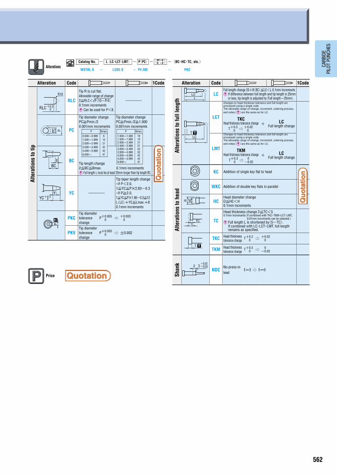
AlterationsCatalog No. - L (LC・LCT・LMT) - P(PC)- RT=0
R =0 -(BC・HC・TC, etc.)
WSTAL 6 - LC65.0 - P4.500 - PKC
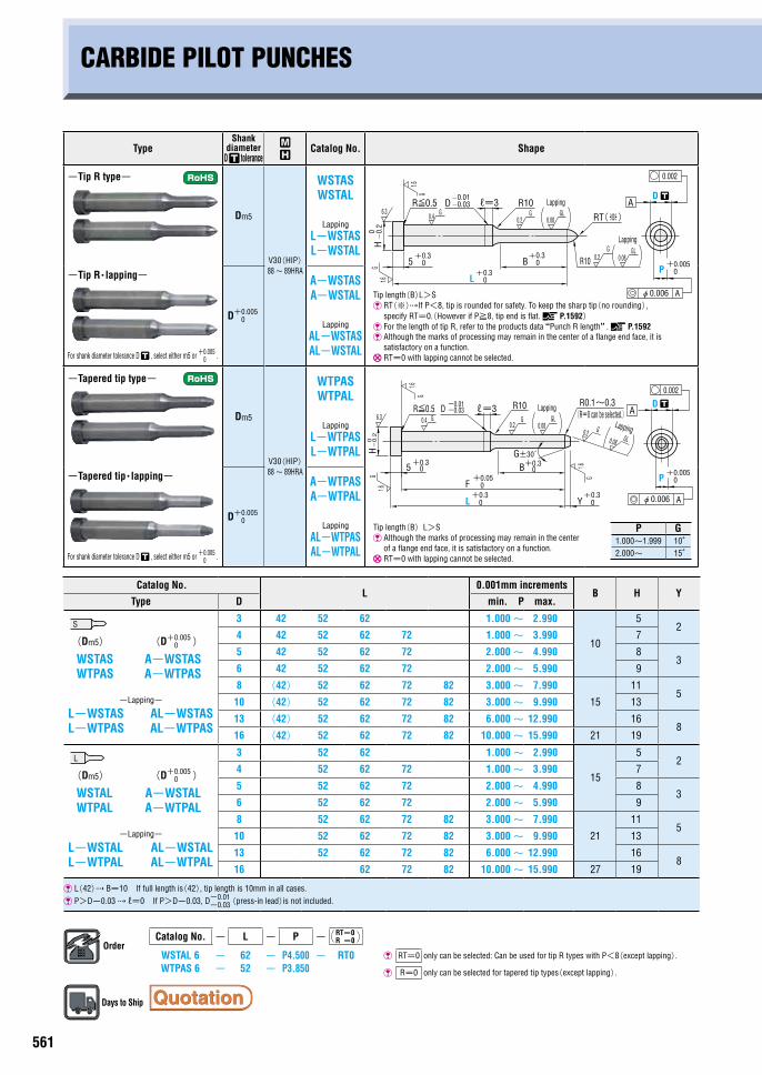
CARBIDE PILOT PUNCHES
TypeShank
diameter D tolerance
~
Catalog No. Shape
-Tip R type-
Dm5
V30(HIP) 88~ 89HRA
WSTAS WSTAL
Lapping
L-WSTAS L-WSTAL
Tip length(B)L>S �RT(※)If P<8, tip is rounded for safety. To keep the sharp tip(no rounding),
specify RT=0.(However if P≧8, tip end is flat. P.1592) For the length of tip R, refer to the products data “Punch R length”. P.1592 Although the marks of processing may remain in the center of a flange end face, it is
satisfactory on a function. RT=0 with lapping cannot be selected.
-Tip R・lapping-
For shank diameter tolerance D , select either m5 or +0.005
0 .
D+0.005 0
A-WSTAS A-WSTAL
Lapping
AL-WSTAS AL-WSTAL
-Tapered tip type-
Dm5
V30(HIP) 88~ 89HRA
WTPAS WTPAL
Lapping
L-WTPAS L-WTPAL
-Tapered tip・lapping-
For shank diameter tolerance D , select either m5 or +0.005
0 .
D+0.005 0
A-WTPAS A-WTPAL
Lapping
AL-WTPAS AL-WTPAL
Tip length(B)L>S Although the marks of processing may remain in the center
of a flange end face, it is satisfactory on a function. RT=0 with lapping cannot be selected.
Catalog No.L
0.001mm incrementsB H Y
Type D min. P max.
3 42 52 62 1.000~ 2.990
10
52
(Dm5) (D+0.005 0 )
WSTAS A-WSTAS WTPAS A-WTPAS
-Lapping- L-WSTAS AL-WSTAS L-WTPAS AL-WTPAS
4 42 52 62 72 1.000~ 3.990 7
5 42 52 62 72 2.000~ 4.990 83
6 42 52 62 72 2.000~ 5.990 9
8 (42) 52 62 72 82 3.000~ 7.990
15
115
10 (42) 52 62 72 82 3.000~ 9.990 13
13 (42) 52 62 72 82 6.000~ 12.990 168
16 (42) 52 62 72 82 10.000~ 15.990 21 19
3 52 62 1.000~ 2.990
15
52
(Dm5) (D+0.005 0 )
WSTAL A-WSTAL WTPAL A-WTPAL
-Lapping- L-WSTAL AL-WSTAL L-WTPAL AL-WTPAL
4 52 62 72 1.000~ 3.990 7
5 52 62 72 2.000~ 4.990 83
6 52 62 72 2.000~ 5.990 9
8 52 62 72 82 3.000~ 7.990
21
115
10 52 62 72 82 3.000~ 9.990 13
13 52 62 72 82 6.000~ 12.990 168
16 62 72 82 10.000~ 15.990 27 19
L(42) B=10 If full length is(42), tip length is 10mm in all cases.
P>D-0.03 ℓ=0 If P>D-0.03, D-0.01-0.03(press-in lead)is not included.
OrderCatalog No. - L - P - RT=0
R =0
WSTAL 6 - 62 - P4.500 - RT0 RT=0 only can be selected: Can be used for tip R types with P<8(except lapping).
WTPAS 6 - 52 - P3.850 R=0 only can be selected for tapered tip types(except lapping).
Days to Ship
Alteration Code 1Code
Alte
ratio
ns to
tip
RLC
Tip R is cut flat. Allowable range of change 2≦RLC<√P(10-P/4) 0.1mm increments Can be used for P<8.
-
PC
Tip diameter change PC≧Pmin./2 0.001mm increments
Tip diameter change PC≧Pmin./2≧1.000 0.001mm increments
BCTip length change 2≦BC≦Bmax. 0.1mm increments Full length L must be at least 25mm longer than tip length BC.
YC -
Tip taper length change ・If P<2.0, 1≦YC≦P×2.83-0.3 ・If P≧2.0, 1≦YC≦P×1.86-0.3≦12 L(LC)+YC≦Lmax.+8 0.1mm increments
PKCTip diameter tolerance change
P+0.0050 ⇨ +0.003
0
PKVTip diameter tolerance change
P+0.0050 ⇨ ±0.002
Alteration Code 1Code
Alte
ratio
ns to
full
leng
th
LCFull length change 25+B(BC)≦LC<L 0.1mm increments �If difference between full length and tip length is 25mm
or less, tip length is adjusted to(Full length-25mm).
LCT
Changes to head thickness tolerance and full length are processed using a single code. The allowable range of change, increment, ordering process, and notes()are the same as for LC.
TKC Head thickness tolerance change
T+0.30 ⇨ +0.02
0
+ LC Full length change
LMT
Changes to head thickness tolerance and full length are processed using a single code. The allowable range of change, increment, ordering process, and notes()are the same as for LC.
TKM Head thickness tolerance change
T+0.30 ⇨ 0
-0.02
+ LC Full length change
Alte
ratio
ns to
hea
d
KC Addition of single key flat to head
WKC Addition of double key flats in parallel
HCHead diameter change D≦HC<H 0.1mm increments
TC
Head thickness change 2≦TC<5 0.1mm increments( If combined with TKC・TKM・LCT・LMT,
0.01mm increments can be selected.) �Full length L is shortened by(5-TC).
If combined with LC・LCT・LMT, full length remains as specified.
TKC Head thickness tolerance change T+0.3
0 ⇨ +0.020
TKM Head thickness tolerance change T+0.3
0 ⇨ 0-0.02
Shan
k
NDCNo press-in lead
ℓ=3 ⇨ ℓ=0
Price
P G1.000~1.999 10°2.000~ 15°
+0.0050P
B
H
5+0.3
0
-0.
20
L+0.3
0
+0.30
R10D-0.01-0.03R≦0.5
6.3
1.6G
0.4 G0.2
G
R10
D ┄
0.2G
0.002
Aφ0.006
A
1.6G
ℓ=3
0.08GL
GL0.08
RT(※)
Lapping
Lapping
R0.1~0.3R≦0.5 -0.03
-0.01D R10
0+0.3
0+0.3
L
0-
0.2
0+0.35 B
F+0.05
0
Y+0.3
0
G±30́
D
0.2 G
H
6.31.6
G0.4 G
0.2G
1.6G
0.002
A
1.6G
ℓ=3
+0.0050P
Aφ0.006
0.08GL
GL0.08
(R=0 can be selected.)Lapping
Lapping
┄
L
S
P Bmax.
0.500~0.999 1.000~1.999 2.000~2.999 3.000~3.999 4.000~5.999 6.000~
6 15 21 32 42 47
P Bmax.
1.000~1.499 1.500~1.999 2.000~2.499 2.500~2.999 3.000~3.499 3.500~3.999 4,000~4.999 5,000~5.999 6.000~
15 15 21 21 32 32 42 42 47B
BC
PPCP
YC+0.30
RLC 0+0.3
R10
Y
┄
-0.03-0.01
Dℓ
TTC
T ┄
H HC
LCL
T ┄
LCL
561 562
CARB
IDE
PILO
T PU
NCHE
S
AlterationsCatalog No. - L (LC・LCT・LMT) - P(PC)- RT=0
R =0 -(BC・HC・TC, etc.)
WSTAL 6 - LC65.0 - P4.500 - PKC
CARBIDE PILOT PUNCHES
TypeShank
diameter D tolerance
~
Catalog No. Shape
-Tip R type-
Dm5
V30(HIP) 88~ 89HRA
WSTAS WSTAL
Lapping
L-WSTAS L-WSTAL
Tip length(B)L>S �RT(※)If P<8, tip is rounded for safety. To keep the sharp tip(no rounding),
specify RT=0.(However if P≧8, tip end is flat. P.1592) For the length of tip R, refer to the products data “Punch R length”. P.1592 Although the marks of processing may remain in the center of a flange end face, it is
satisfactory on a function. RT=0 with lapping cannot be selected.
-Tip R・lapping-
For shank diameter tolerance D , select either m5 or +0.005
0 .
D+0.005 0
A-WSTAS A-WSTAL
Lapping
AL-WSTAS AL-WSTAL
-Tapered tip type-
Dm5
V30(HIP) 88~ 89HRA
WTPAS WTPAL
Lapping
L-WTPAS L-WTPAL
-Tapered tip・lapping-
For shank diameter tolerance D , select either m5 or +0.005
0 .
D+0.005 0
A-WTPAS A-WTPAL
Lapping
AL-WTPAS AL-WTPAL
Tip length(B)L>S Although the marks of processing may remain in the center
of a flange end face, it is satisfactory on a function. RT=0 with lapping cannot be selected.
Catalog No.L
0.001mm incrementsB H Y
Type D min. P max.
3 42 52 62 1.000~ 2.990
10
52
(Dm5) (D+0.005 0 )
WSTAS A-WSTAS WTPAS A-WTPAS
-Lapping- L-WSTAS AL-WSTAS L-WTPAS AL-WTPAS
4 42 52 62 72 1.000~ 3.990 7
5 42 52 62 72 2.000~ 4.990 83
6 42 52 62 72 2.000~ 5.990 9
8 (42) 52 62 72 82 3.000~ 7.990
15
115
10 (42) 52 62 72 82 3.000~ 9.990 13
13 (42) 52 62 72 82 6.000~ 12.990 168
16 (42) 52 62 72 82 10.000~ 15.990 21 19
3 52 62 1.000~ 2.990
15
52
(Dm5) (D+0.005 0 )
WSTAL A-WSTAL WTPAL A-WTPAL
-Lapping- L-WSTAL AL-WSTAL L-WTPAL AL-WTPAL
4 52 62 72 1.000~ 3.990 7
5 52 62 72 2.000~ 4.990 83
6 52 62 72 2.000~ 5.990 9
8 52 62 72 82 3.000~ 7.990
21
115
10 52 62 72 82 3.000~ 9.990 13
13 52 62 72 82 6.000~ 12.990 168
16 62 72 82 10.000~ 15.990 27 19
L(42) B=10 If full length is(42), tip length is 10mm in all cases.
P>D-0.03 ℓ=0 If P>D-0.03, D-0.01-0.03(press-in lead)is not included.
OrderCatalog No. - L - P - RT=0
R =0
WSTAL 6 - 62 - P4.500 - RT0 RT=0 only can be selected: Can be used for tip R types with P<8(except lapping).
WTPAS 6 - 52 - P3.850 R=0 only can be selected for tapered tip types(except lapping).
Days to Ship
Alteration Code 1Code
Alte
ratio
ns to
tip
RLC
Tip R is cut flat. Allowable range of change 2≦RLC<√P(10-P/4) 0.1mm increments Can be used for P<8.
-
PC
Tip diameter change PC≧Pmin./2 0.001mm increments
Tip diameter change PC≧Pmin./2≧1.000 0.001mm increments
BCTip length change 2≦BC≦Bmax. 0.1mm increments Full length L must be at least 25mm longer than tip length BC.
YC -
Tip taper length change ・If P<2.0, 1≦YC≦P×2.83-0.3 ・If P≧2.0, 1≦YC≦P×1.86-0.3≦12 L(LC)+YC≦Lmax.+8 0.1mm increments
PKCTip diameter tolerance change
P+0.0050 ⇨ +0.003
0
PKVTip diameter tolerance change
P+0.0050 ⇨ ±0.002
Alteration Code 1Code
Alte
ratio
ns to
full
leng
th
LCFull length change 25+B(BC)≦LC<L 0.1mm increments �If difference between full length and tip length is 25mm
or less, tip length is adjusted to(Full length-25mm).
LCT
Changes to head thickness tolerance and full length are processed using a single code. The allowable range of change, increment, ordering process, and notes()are the same as for LC.
TKC Head thickness tolerance change
T+0.30 ⇨ +0.02
0
+ LC Full length change
LMT
Changes to head thickness tolerance and full length are processed using a single code. The allowable range of change, increment, ordering process, and notes()are the same as for LC.
TKM Head thickness tolerance change
T+0.30 ⇨ 0
-0.02
+ LC Full length change
Alte
ratio
ns to
hea
dKC Addition of single key flat to head
WKC Addition of double key flats in parallel
HCHead diameter change D≦HC<H 0.1mm increments
TC
Head thickness change 2≦TC<5 0.1mm increments( If combined with TKC・TKM・LCT・LMT,
0.01mm increments can be selected.) �Full length L is shortened by(5-TC).
If combined with LC・LCT・LMT, full length remains as specified.
TKC Head thickness tolerance change T+0.3
0 ⇨ +0.020
TKM Head thickness tolerance change T+0.3
0 ⇨ 0-0.02
Shan
k
NDCNo press-in lead
ℓ=3 ⇨ ℓ=0
Price
P G1.000~1.999 10°2.000~ 15°
+0.0050P
B
H
5+0.3
0
-0.
20
L+0.3
0
+0.30
R10D-0.01-0.03R≦0.5
6.3
1.6G
0.4 G0.2
G
R10
D ┄
0.2G
0.002
Aφ0.006
A
1.6G
ℓ=3
0.08GL
GL0.08
RT(※)
Lapping
Lapping
R0.1~0.3R≦0.5 -0.03
-0.01D R10
0+0.3
0+0.3
L
0-
0.2
0+0.35 B
F+0.05
0
Y+0.3
0
G±30́
D
0.2 G
H
6.3
1.6G
0.4 G0.2
G
1.6G
0.002
A
1.6G
ℓ=3
+0.0050P
Aφ0.006
0.08GL
GL0.08
(R=0 can be selected.)Lapping
Lapping
┄
L
S
P Bmax.
0.500~0.999 1.000~1.999 2.000~2.999 3.000~3.999 4.000~5.999 6.000~
6 15 21 32 42 47
P Bmax.
1.000~1.499 1.500~1.999 2.000~2.499 2.500~2.999 3.000~3.499 3.500~3.999 4,000~4.999 5,000~5.999 6.000~
15 15 21 21 32 32 42 42 47B
BC
PPCP
YC+0.30
RLC 0+0.3
R10
Y
┄
-0.03-0.01
Dℓ
TTC
T ┄
H HC
LCL
T ┄
LCL
563 564
CARB
IDE
PILO
T PU
NCHE
S
AlterationsCatalog No. - L(LC・LCT・LMT)- P(PC)- RT=0
R =0 -(BC・HC・TC, etc.)H-WSTAL 6 - LC65.0 - P4.50 - RT0 - TKC
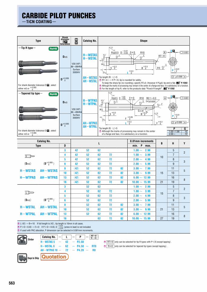
CARBIDE PILOT PUNCHES-TiCN COATING-
PRODUCTS DATA
TypeShank
diameter D
tolerance
~
Catalog No. Shape
-Tip R type-
For shank diameter tolerance D , select either m5 or +0.005
0 .
Dm5
V30(HIP) 88~89HRA
Surface 3000HV
H-WSTAS H-WSTAL
Tip length(B)L>S �RT(※) If P<8, tip is rounded for safety.
To keep the sharp tip(no rounding), specify RT=0.(However if P≧8, tip end is flat. P.1592) Although the marks of processing may remain in the center of a flange end face, it is satisfactory on a function. For the length of tip R, refer to the products data “Punch R length”. P.1592
D+0.0050
AH-WSTAS AH-WSTAL
-Tapered tip type-
For shank diameter tolerance D , select either m5 or +0.005
0 .
Dm5
V30(HIP) 88~89HRA
Surface 3000HV
H-WTPAS H-WTPAL
D+0.0050
AH-WTPAS AH-WTPAL Tip length(B)L>S
Although the marks of processing may remain in the center of a flange end face, it is satisfactory on a function.
Catalog No.L
0.01mm incrementsB H Y
Type D min. P max.
3 42 52 62 1.00~ 2.99
10
52
4 42 52 62 72 1.00~ 3.99 7
(Dm5)
H-WSTAS
H-WTPAS
(D+0.0050 )
AH-WSTAS
AH-WTPAS
5 42 52 62 72 2.00~ 4.99 83
6 42 52 62 72 2.00~ 5.99 9
8 (42) 52 62 72 82 3.00~ 7.99
15
115
10 (42) 52 62 72 82 3.00~ 9.99 13
13 (42) 52 62 72 82 6.00~ 12.99 168
16 (42) 52 62 72 82 10.00~ 15.99 21 19
3 52 62 1.00~ 2.99
15
52
4 52 62 72 1.00~ 3.99 7
(Dm5)
H-WSTAL
H-WTPAL
(D+0.0050 )
AH-WSTAL
AH-WTPAL
5 52 62 72 2.00~ 4.99 83
6 52 62 72 2.00~ 5.99 9
8 52 62 72 82 3.00~ 7.99
21
115
10 52 62 72 82 3.00~ 9.99 13
13 52 62 72 82 6.00~ 12.99 168
16 62 72 82 10.00~ 15.99 27 19
L(42) B=10 If full length is(42), tip length is 10mm in all cases.
P>D-0.03 ℓ=0 If P>D-0.03, D -0.01-0.03(press-in lead)is not included.
If used with PKC alteration, P dimension can be selected in 0.001mm increments.
OrderCatalog No. - L - P - RT=0
R =0
H-WSTAS 5 - 42 - P2.50 RT=0 only can be selected for tip R types with P<8(except lapping).
H-WSTAL 8 - 62 - P4.50 - RT0 R=0 only can be selected for tapered tip types(except lapping).
AH-WTPAS 10 - 72 - P4.20 - R0
Days to Ship
L
D
P
R0.1~0.3
G±30́
0.4
+0.3
R≦0.5
1.6H-
0.2
0
1.6
5G
0
6.3
+0.30
+0.30
+0.05
G
0F
-0.03-0.01D
0.2G
B
R10
+0.3Y 0
G
1.6G
0.2
G0.002
φ0.006
Aℓ=3
+0.010
A
┄
(R=0 can be selected.)
P G1.00~1.99 10°2.00~ 15°
L
S
Alteration Code 1Code
Alte
ratio
ns to
tip
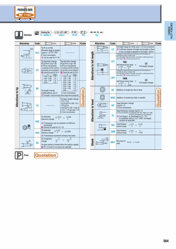
RLC
Tip R is cut flat. Allowable range of change 2≦RLC<√P(10-P/4) 0.1mm increments Can be used for P<8.
-
PC
Tip diameter change PC≧Pmin./2≧1.00 0.01mm increments (If combined with PKC, 0.001mm increments can be selected.) Cannot be used for D3・4.
Tip diameter change PC≧Pmin./2≧1.00 0.01mm increments (If combined with PKC, 0.001mm increments can be selected.) Cannot be used for D3・4.
BCTip length change 2≦BC≦Bmax.≦L/2 0.1mm increments Full length L must be at least 25mm longer than tip length BC.
YC -
Tip taper length change ・If P<2.0, 1≦YC≦P×2.83-0.3 ・If P≧2.0, 1≦YC≦P×1.86-0.3≦12 L(LC)+YC≦Lmax.+8 0.1mm increments
PKC
Tip diameter tolerance change
P+0.010 ⇨ +0.005
0
P dimension can be selected in 0.001mm increments.
Cannot be used for D>13.
PKVTip diameter tolerance change
P+0.010 ⇨ ±0.005
P dimension increment remains the same.
SC
Tip roughness change
⇨
The base material is finished before the coating is applied. RT=0 and R=0 cannot be selected.
P Bmax.1.00~1.99 2.00~2.99 3.00~3.99 4.00~
15 21 32 41
P Bmax.1.00~1.49 1.50~1.99 2.00~2.49 2.50~2.99 3.00~3.49 3.50~3.99 4.00~4.99 5.00~
15 15 21 21 32 32 41 41
Alteration Code 1Code
Alte
ratio
ns to
full
leng
th
LCFull length change 25+B(BC)≦LC<L 0.1mm increments �If difference between full length and tip length is 25mm
or less, tip length is adjusted to(Full length-25mm).
LCT
Changes to head thickness tolerance and full length are processed using a single code. The allowable range of change, increment, ordering process, and notes()are the same as for LC.
TKC Head thickness tolerance change
T+0.30 ⇨ +0.02
0
+LC
Full length change
LMT
Changes to head thickness tolerance and full length are processed using a single code. The allowable range of change, increment, ordering process, and notes()are the same as for LC.
TKM Head thickness tolerance change
T+0.30 ⇨ 0
-0.02
+LC
Full length change
Alte
ratio
ns to
hea
d
KC Addition of single key flat to head
WKC Addition of double key flats in parallel
HCHead diameter change D≦HC<H 0.1mm increments
TC
Head thickness change 2≦TC<5 0.1mm increments( If combined with TKC・TKM・LCT・LMT,
0.01mm increments can be selected.) �Full length L is shortened by(5-TC).
If combined with LC・LCT・LMT, full length remains as specified.
TKC Head thickness tolerance change T+0.3
0 ⇨ +0.020
TKM Head thickness tolerance change T+0.3
0 ⇨ 0-0.02
Shan
k
NDC No press-in lead
ℓ=3 ⇨ ℓ=0
Price
BCB
PC P
0.08GL
P
RLC 0+0.3
R10
YC+0.30
Y
┄
-0.03-0.01
Dℓ
TTC
T ┄
H HC
LCL
T ┄
LCL
0.2G
0.08GL
P.1604
LP
D
0.4
G
R≦0.5
0+0.3
6.3
H0-
0.2
5
1.6
+0.3
G
0
+0.30
-0.03-0.01
DG
B
0.2
R10
R10 0.2G
+0.010
0.002
φ0.006 A
1.6G
Aℓ=3RT(※)
┄
563 564
CARB
IDE
PILO
T PU
NCHE
S
AlterationsCatalog No. - L(LC・LCT・LMT)- P(PC)- RT=0
R =0 -(BC・HC・TC, etc.)H-WSTAL 6 - LC65.0 - P4.50 - RT0 - TKC
CARBIDE PILOT PUNCHES-TiCN COATING-
PRODUCTS DATA
TypeShank
diameter D
tolerance
~
Catalog No. Shape
-Tip R type-
For shank diameter tolerance D , select either m5 or +0.005
0 .
Dm5
V30(HIP) 88~89HRA
Surface 3000HV
H-WSTAS H-WSTAL
Tip length(B)L>S �RT(※) If P<8, tip is rounded for safety.
To keep the sharp tip(no rounding), specify RT=0.(However if P≧8, tip end is flat. P.1592) Although the marks of processing may remain in the center of a flange end face, it is satisfactory on a function. For the length of tip R, refer to the products data “Punch R length”. P.1592
D+0.0050
AH-WSTAS AH-WSTAL
-Tapered tip type-
For shank diameter tolerance D , select either m5 or +0.005
0 .
Dm5
V30(HIP) 88~89HRA
Surface 3000HV
H-WTPAS H-WTPAL
D+0.0050
AH-WTPAS AH-WTPAL Tip length(B)L>S
Although the marks of processing may remain in the center of a flange end face, it is satisfactory on a function.
Catalog No.L
0.01mm incrementsB H Y
Type D min. P max.
3 42 52 62 1.00~ 2.99
10
52
4 42 52 62 72 1.00~ 3.99 7
(Dm5)
H-WSTAS
H-WTPAS
(D+0.0050 )
AH-WSTAS
AH-WTPAS
5 42 52 62 72 2.00~ 4.99 83
6 42 52 62 72 2.00~ 5.99 9
8 (42) 52 62 72 82 3.00~ 7.99
15
115
10 (42) 52 62 72 82 3.00~ 9.99 13
13 (42) 52 62 72 82 6.00~ 12.99 168
16 (42) 52 62 72 82 10.00~ 15.99 21 19
3 52 62 1.00~ 2.99
15
52
4 52 62 72 1.00~ 3.99 7
(Dm5)
H-WSTAL
H-WTPAL
(D+0.0050 )
AH-WSTAL
AH-WTPAL
5 52 62 72 2.00~ 4.99 83
6 52 62 72 2.00~ 5.99 9
8 52 62 72 82 3.00~ 7.99
21
115
10 52 62 72 82 3.00~ 9.99 13
13 52 62 72 82 6.00~ 12.99 168
16 62 72 82 10.00~ 15.99 27 19
L(42) B=10 If full length is(42), tip length is 10mm in all cases.
P>D-0.03 ℓ=0 If P>D-0.03, D -0.01-0.03(press-in lead)is not included.
If used with PKC alteration, P dimension can be selected in 0.001mm increments.
OrderCatalog No. - L - P - RT=0
R =0
H-WSTAS 5 - 42 - P2.50 RT=0 only can be selected for tip R types with P<8(except lapping).
H-WSTAL 8 - 62 - P4.50 - RT0 R=0 only can be selected for tapered tip types(except lapping).
AH-WTPAS 10 - 72 - P4.20 - R0
Days to Ship
L
D
P
R0.1~0.3
G±30́
0.4
+0.3
R≦0.5
1.6H-
0.2
0
1.6
5
G
0
6.3
+0.30
+0.30
+0.05
G
0F
-0.03-0.01D
0.2G
B
R10
+0.3Y 0
G
1.6G
0.2
G
0.002
φ0.006
Aℓ=3
+0.010
A
┄
(R=0 can be selected.)
P G1.00~1.99 10°2.00~ 15°
L
S
Alteration Code 1Code
Alte
ratio
ns to
tip
RLC
Tip R is cut flat. Allowable range of change 2≦RLC<√P(10-P/4) 0.1mm increments Can be used for P<8.
-
PC
Tip diameter change PC≧Pmin./2≧1.00 0.01mm increments (If combined with PKC, 0.001mm increments can be selected.) Cannot be used for D3・4.
Tip diameter change PC≧Pmin./2≧1.00 0.01mm increments (If combined with PKC, 0.001mm increments can be selected.) Cannot be used for D3・4.
BCTip length change 2≦BC≦Bmax.≦L/2 0.1mm increments Full length L must be at least 25mm longer than tip length BC.
YC -
Tip taper length change ・If P<2.0, 1≦YC≦P×2.83-0.3 ・If P≧2.0, 1≦YC≦P×1.86-0.3≦12 L(LC)+YC≦Lmax.+8 0.1mm increments
PKC
Tip diameter tolerance change
P+0.010 ⇨ +0.005
0
P dimension can be selected in 0.001mm increments.
Cannot be used for D>13.
PKVTip diameter tolerance change
P+0.010 ⇨ ±0.005
P dimension increment remains the same.
SC
Tip roughness change
⇨
The base material is finished before the coating is applied. RT=0 and R=0 cannot be selected.
P Bmax.1.00~1.99 2.00~2.99 3.00~3.99 4.00~
15 21 32 41
P Bmax.1.00~1.49 1.50~1.99 2.00~2.49 2.50~2.99 3.00~3.49 3.50~3.99 4.00~4.99 5.00~
15 15 21 21 32 32 41 41
Alteration Code 1Code
Alte
ratio
ns to
full
leng
th
LCFull length change 25+B(BC)≦LC<L 0.1mm increments �If difference between full length and tip length is 25mm
or less, tip length is adjusted to(Full length-25mm).
LCT
Changes to head thickness tolerance and full length are processed using a single code. The allowable range of change, increment, ordering process, and notes()are the same as for LC.
TKC Head thickness tolerance change
T+0.30 ⇨ +0.02
0
+LC
Full length change
LMT
Changes to head thickness tolerance and full length are processed using a single code. The allowable range of change, increment, ordering process, and notes()are the same as for LC.
TKM Head thickness tolerance change
T+0.30 ⇨ 0
-0.02
+LC
Full length change
Alte
ratio
ns to
hea
dKC Addition of single key flat to head
WKC Addition of double key flats in parallel
HCHead diameter change D≦HC<H 0.1mm increments
TC
Head thickness change 2≦TC<5 0.1mm increments( If combined with TKC・TKM・LCT・LMT,
0.01mm increments can be selected.) �Full length L is shortened by(5-TC).
If combined with LC・LCT・LMT, full length remains as specified.
TKC Head thickness tolerance change T+0.3
0 ⇨ +0.020
TKM Head thickness tolerance change T+0.3
0 ⇨ 0-0.02
Shan
k
NDC No press-in lead
ℓ=3 ⇨ ℓ=0
Price
BCB
PC P
0.08GL
P
RLC 0+0.3
R10
YC+0.30
Y
┄
-0.03-0.01
Dℓ
TTC
T ┄
H HC
LCL
T ┄
LCL
0.2G
0.08GL
P.1604
LP
D
0.4
G
R≦0.5
0+0.3
6.3
H0-
0.2
5
1.6
+0.3
G
0
+0.30
-0.03-0.01
DG
B
0.2
R10
R10 0.2G
+0.010
0.002
φ0.006 A
1.6G
Aℓ=3RT(※)
┄
565 566
CARB
IDE
PILO
T PU
NCHE
S
AlterationsCatalog No. - L (LC・LCT) - P(PC)- T - RT=0
R =0 -(BC・YC・WKD…etc.)WKSTAL 6 - LC65.0 - P4.500 - T8 - PKC
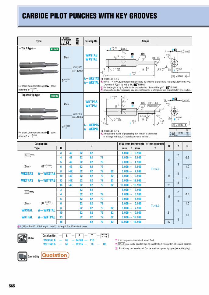
CARBIDE PILOT PUNCHES WITH KEY GROOVES
TypeShank
diameter D
tolerance
~
Catalog No. Shape
-Tip R type-
For shank diameter tolerance D , select
either m5 or +0.005 0 .
Dm5
V30(HIP) 88~89HRA
WKSTAS WKSTAL
Tip length(B)L>S �RT(※) If P<8, tip is rounded for safety. To keep the sharp tip(no rounding), specify RT=0. (However if P≧8, tip end is flat. P.1592) For the length of tip R, refer to the products data “Punch R length”. P.1592 Although the marks of processing may remain in the center of a flange end face, it is satisfactory on a function.
D+0.0050
A-WKSTAS A-WKSTAL
-Tapered tip type-
For shank diameter tolerance D , select
either m5 or +0.005 0 .
Dm5
V30(HIP) 88~89HRA
WKTPAS WKTPAL
D+0.0050
A-WKTPAS A-WKTPAL Tip length(B)L>S
Although the marks of processing may remain in the center of a flange end face, it is satisfactory on a function.
Catalog No.L
0.001mm increments 0.1mm incrementsB Y U
Type D min. P max. T
3 42 52 62 1.000~ 2.990
T>5.0
10
20.54 42 52 62 72 1.000~ 3.990
(Dm5)
WKSTAS
WKTPAS
(D+0.0050 )
A-WKSTAS
A-WKTPAS
5 42 52 62 72 2.000~ 4.9903
6 42 52 62 72 2.000~ 5.990 1.0
8 (42) 52 62 72 82 3.000~ 7.990
155
1.510 (42) 52 62 72 82 3.000~ 9.990
13 (42) 52 62 72 82 6.000~ 12.9908
16 (42) 52 62 72 82 10.000~ 15.990 21
3 52 62 1.000~ 2.990
T>5.0
15
20.54 52 62 72 1.000~ 3.990
(Dm5)
WKSTAL
WKTPAL
(D +0.0050 )
A-WKSTAL
A-WKTPAL
5 52 62 72 2.000~ 4.9903
6 52 62 72 2.000~ 5.990 1.0
8 52 62 72 82 3.000~ 7.990
215
1.510 52 62 72 82 3.000~ 9.990
13 52 62 72 82 6.000~ 12.9908
16 62 72 82 10.000~ 15.990 27
L(42) B=10 If full length L is(42), tip length B is 10mm in all cases.
OrderCatalog No. - L - P - T - RT=0
R =0
WKSTAL 6 - 62 - P4.500 - T10 If no key groove is required, select T=L.
WKTPAS 5 - 52 - P2.015 - T8 - R0 RT=0 only can be selected: Can be used for tip R types withP<8(except lapping).
R=0 only can be selected: Can be used for tapered tip types(except lapping).
Days to Ship
P G1.000~1.999 10°2.000~ 15°
0.4
+0.3
G
0
+0.30
L
G
B
0.2
R10
R10 0.2G
+0.005P 0
D ┄T 5±0.1
3 D-0.03
D ┄
1.61.6
1.6G
U+0.2
0
φ0.006 A
+0.050
-0.01
A 0.002
6.3
RT(※)
0.2G
B
R10
+0.3Y 0
G
1.6G
0.2
-0.03
1.6G 3 D
0+0.3 0
+0.3
L
0.4
T
G
1.61.6
5±0.1
D ┄
0U
0
+0.2
D ┄
Aφ0.006
A
-0.01
+0.050
0.002
6.3
+0.005P
R0.1~0.3
G±30́
(R=0 can be selected.)
Alteration Code 1Code
Alte
ratio
ns to
tip
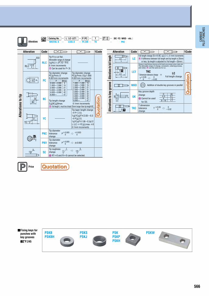
RLC
Tip R is cut flat. Allowable range of change 2≦RLC<√P(10-P/4) 0.1mm increments Can be used for P<8.
-
PC
Tip diameter change PC≧Pmin./2 0.001mm increments
Tip diameter change PC≧Pmin./2≧1.000 0.001mm increments
BCTip length change 2≦BC≦Bmax. 0.1mm increments Full length L must be at least 25mm longer than tip length BC.
YC -
Tip taper length change ・If P<2.0, 1≦YC≦P×2.83-0.3 ・If P≧2.0, 1≦YC≦P×1.86-0.3≦12 L(LC)+YC≦Lmax.+8 0.1mm increments
PKCTip diameter tolerance change
P+0.0050 ⇨ +0.003
0
PKVTip diameter tolerance change
P+0.0050 ⇨ ±0.002
SCTip roughness change
⇨
RT=0 and R=0 cannot be selected.
P Bmax.1.000~1.499 1.500~1.999 2.000~2.499 2.500~2.999 3.000~3.499 3.500~3.999 4.000~4.999 5.000~5.999 6.000~
15 15 21 21 32 32 42 42 47
P Bmax.0.500~0.999 1.000~1.999 2.000~2.999 3.000~3.999 4.000~5.999 6.000~
6 15 21 32 42 47
BCB
PC PP
0.08GL
RLC 0+0.3
R10
YC+0.30
Y
┄
L
S
Alteration Code 1Code
Altera
tions
to fu
ll len
gth LCFull length change 25+B(BC)≦LC<L 0.1mm increments �If difference between full length and tip length is 25mm
or less, tip length is adjusted to(Full length-25mm).
LCT
Changes to head thickness tolerance and full length are processed using a single code. The allowable range of change, increment, ordering process, and notes()are the same as for LC.
TKC T dimension tolerance change T+0.05
0 ⇨ 0-0.02
+LC
Full length change
Alte
ratio
ns to
key g
roov
e
WKD Addition of double key grooves in parallel
UK
Key groove depth change
�Cannot be used for D3.
TKCT dimension tolerance change
T +0.050 ⇨ 0
-0.02
D UK4・5 0.7
6 1.28~16 1.7
UKU
T ┄
LLC
T ┄
LLC
Price
■�Fixing keys for punches with key grooves
P.245
PSKB PSKBH
PSKS PSKJ
PSK PSKP PSKH
PSKW
0.2G
0.08GL
565 566
CARB
IDE
PILO
T PU
NCHE
S
AlterationsCatalog No. - L (LC・LCT) - P(PC)- T - RT=0
R =0 -(BC・YC・WKD…etc.)WKSTAL 6 - LC65.0 - P4.500 - T8 - PKC
CARBIDE PILOT PUNCHES WITH KEY GROOVES
TypeShank
diameter D
tolerance
~
Catalog No. Shape
-Tip R type-
For shank diameter tolerance D , select
either m5 or +0.005 0 .
Dm5
V30(HIP) 88~89HRA
WKSTAS WKSTAL
Tip length(B)L>S �RT(※) If P<8, tip is rounded for safety. To keep the sharp tip(no rounding), specify RT=0. (However if P≧8, tip end is flat. P.1592) For the length of tip R, refer to the products data “Punch R length”. P.1592 Although the marks of processing may remain in the center of a flange end face, it is satisfactory on a function.
D+0.0050
A-WKSTAS A-WKSTAL
-Tapered tip type-
For shank diameter tolerance D , select
either m5 or +0.005 0 .
Dm5
V30(HIP) 88~89HRA
WKTPAS WKTPAL
D+0.0050
A-WKTPAS A-WKTPAL Tip length(B)L>S
Although the marks of processing may remain in the center of a flange end face, it is satisfactory on a function.
Catalog No.L
0.001mm increments 0.1mm incrementsB Y U
Type D min. P max. T
3 42 52 62 1.000~ 2.990
T>5.0
10
20.54 42 52 62 72 1.000~ 3.990
(Dm5)
WKSTAS
WKTPAS
(D+0.0050 )
A-WKSTAS
A-WKTPAS
5 42 52 62 72 2.000~ 4.9903
6 42 52 62 72 2.000~ 5.990 1.0
8 (42) 52 62 72 82 3.000~ 7.990
155
1.510 (42) 52 62 72 82 3.000~ 9.990
13 (42) 52 62 72 82 6.000~ 12.9908
16 (42) 52 62 72 82 10.000~ 15.990 21
3 52 62 1.000~ 2.990
T>5.0
15
20.54 52 62 72 1.000~ 3.990
(Dm5)
WKSTAL
WKTPAL
(D +0.0050 )
A-WKSTAL
A-WKTPAL
5 52 62 72 2.000~ 4.9903
6 52 62 72 2.000~ 5.990 1.0
8 52 62 72 82 3.000~ 7.990
215
1.510 52 62 72 82 3.000~ 9.990
13 52 62 72 82 6.000~ 12.9908
16 62 72 82 10.000~ 15.990 27
L(42) B=10 If full length L is(42), tip length B is 10mm in all cases.
OrderCatalog No. - L - P - T - RT=0
R =0
WKSTAL 6 - 62 - P4.500 - T10 If no key groove is required, select T=L.
WKTPAS 5 - 52 - P2.015 - T8 - R0 RT=0 only can be selected: Can be used for tip R types withP<8(except lapping).
R=0 only can be selected: Can be used for tapered tip types(except lapping).
Days to Ship
P G1.000~1.999 10°2.000~ 15°
0.4
+0.3
G
0
+0.30
L
G
B
0.2
R10
R10 0.2G
+0.005P 0
D ┄T 5±0.1
3 D-0.03
D ┄
1.61.6
1.6G
U+0.2
0
φ0.006 A
+0.050
-0.01
A 0.002
6.3
RT(※)
0.2G
B
R10
+0.3Y 0
G
1.6G
0.2
-0.03
1.6G 3 D
0+0.3 0
+0.3
L
0.4
T
G
1.61.6
5±0.1
D ┄
0U
0
+0.2
D ┄
Aφ0.006
A
-0.01
+0.050
0.002
6.3
+0.005P
R0.1~0.3
G±30́
(R=0 can be selected.)
Alteration Code 1Code
Alte
ratio
ns to
tip
RLC
Tip R is cut flat. Allowable range of change 2≦RLC<√P(10-P/4) 0.1mm increments Can be used for P<8.
-
PC
Tip diameter change PC≧Pmin./2 0.001mm increments
Tip diameter change PC≧Pmin./2≧1.000 0.001mm increments
BCTip length change 2≦BC≦Bmax. 0.1mm increments Full length L must be at least 25mm longer than tip length BC.
YC -
Tip taper length change ・If P<2.0, 1≦YC≦P×2.83-0.3 ・If P≧2.0, 1≦YC≦P×1.86-0.3≦12 L(LC)+YC≦Lmax.+8 0.1mm increments
PKCTip diameter tolerance change
P+0.0050 ⇨ +0.003
0
PKVTip diameter tolerance change
P+0.0050 ⇨ ±0.002
SCTip roughness change
⇨
RT=0 and R=0 cannot be selected.
P Bmax.1.000~1.499 1.500~1.999 2.000~2.499 2.500~2.999 3.000~3.499 3.500~3.999 4.000~4.999 5.000~5.999 6.000~
15 15 21 21 32 32 42 42 47
P Bmax.0.500~0.999 1.000~1.999 2.000~2.999 3.000~3.999 4.000~5.999 6.000~
6 15 21 32 42 47
BCB
PC PP
0.08GL
RLC 0+0.3
R10
YC+0.30
Y
┄
L
S
Alteration Code 1Code
Altera
tions
to fu
ll len
gth LCFull length change 25+B(BC)≦LC<L 0.1mm increments �If difference between full length and tip length is 25mm
or less, tip length is adjusted to(Full length-25mm).
LCT
Changes to head thickness tolerance and full length are processed using a single code. The allowable range of change, increment, ordering process, and notes()are the same as for LC.
TKC T dimension tolerance change T+0.05
0 ⇨ 0-0.02
+LC
Full length change
Alte
ratio
ns to
key g
roov
e
WKD Addition of double key grooves in parallel
UK
Key groove depth change
�Cannot be used for D3.
TKCT dimension tolerance change
T +0.050 ⇨ 0
-0.02
D UK4・5 0.7
6 1.28~16 1.7
UKU
T ┄
LLC
T ┄
LLC
Price
■�Fixing keys for punches with key grooves
P.245
PSKB PSKBH
PSKS PSKJ
PSK PSKP PSKH
PSKW
0.2G
0.08GL
567 568
CARB
IDE
PILO
T PU
NCHE
S
AlterationsCatalog No. - L(LC・LCT) - P(PC)- T - RT=0
R =0 -(BC・YC・WKD…etc.)B-WKSTAL 6 - LC65.5 - P4.500 - T10 - PKC
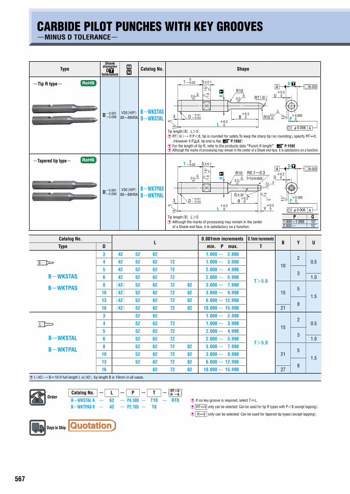
CARBIDE PILOT PUNCHES WITH KEY GROOVES-MINUS D TOLERANCE-
TypeShank
diameter D
tolerance
~
Catalog No. Shape
-Tip R type-
D-0.001-0.006
V30(HIP) 88~89HRA
B-WKSTAS B-WKSTAL
Tip length(B)L>S �RT(※) If P<8, tip is rounded for safety.To keep the sharp tip(no rounding), specify RT=0. (However if P≧8, tip end is flat. P.1592) For the length of tip R, refer to the products data “Punch R length”. P.1592 Although the marks of processing may remain in the center of a Shank end face, it is satisfactory on a function.
-Tapered tip type-
D-0.001-0.006
V30(HIP) 88~89HRA
B-WKTPAS B-WKTPAL
Tip length(B)L>S Although the marks of processing may remain in the center
of a Shank end face, it is satisfactory on a function.
Catalog No.L
0.001mm increments 0.1mm incrementsB Y U
Type D min. P max. T
3 42 52 62 1.000~ 2.990
T>5.0
10
20.54 42 52 62 72 1.000~ 3.990
5 42 52 62 72 2.000~ 4.9903B-WKSTAS
B-WKTPAS
6 42 52 62 72 2.000~ 5.990 1.0
8 (42) 52 62 72 82 3.000~ 7.990
155
1.510 (42) 52 62 72 82 3.000~ 9.990
13 (42) 52 62 72 82 6.000~ 12.9908
16 (42) 52 62 72 82 10.000~ 15.990 21
3 52 62 1.000~ 2.990
T>5.0
15
20.54 52 62 72 1.000~ 3.990
5 52 62 72 2.000~ 4.9903B-WKSTAL
B-WKTPAL
6 52 62 72 2.000~ 5.990 1.0
8 52 62 72 82 3.000~ 7.990
215
1.510 52 62 72 82 3.000~ 9.990
13 52 62 72 82 6.000~ 12.9908
16 62 72 82 10.000~ 15.990 27
L(42) B=10 If full length L is(42), tip length B is 10mm in all cases.
OrderCatalog No. - L - P - T - RT=0
R =0
B-WKSTAL 6 - 62 - P4.500 - T10 - RT0 If no key groove is required, select T=L.
B-WKTPAS 6 - 42 - P2.105 - T8 RT=0 only can be selected: Can be used for tip R types with P<8(except lapping).
R=0 only can be selected: Can be used for tapered tip types(except lapping).
Days to Ship
P G1.000~1.999 10°2.000~ 15°
Alteration Code 1Code
Alte
ratio
ns to
tip
RLC
Tip R is cut flat. Allowable range of change 2≦RLC<√P(10-P/4) 0.1mm increments Can be used for P<8.
-
PC
Tip diameter change PC≧Pmin./2 0.001mm increments
Tip diameter change PC≧Pmin./2≧1.000 0.001mm increments
BCTip length change 2≦BC≦Bmax. 0.1mm increments Full length L must be at least 25mm longer than tip length BC.
YC -
Tip taper length change ・If P<2.0, 1≦YC≦P×2.83-0.3 ・If P≧2.0, 1≦YC≦P×1.86-0.3≦12 L(LC)+YC≦Lmax.+8 0.1mm increments
PKCTip diameter tolerance change
P+0.0050 ⇨ +0.003
0
PKVTip diameter tolerance change
P+0.0050 ⇨ ±0.002
SCTip roughness change
⇨
RT=0 and R=0 cannot be selected.
P Bmax.0.500~0.999 1.000~1.999 2.000~2.999 3.000~3.999 4.000~5.999 6.000~
6 15 21 32 42 47
P Bmax.1.000~1.499 1.500~1.999 2.000~2.499 2.500~2.999 3.000~3.499 3.500~3.999 4.000~4.999 5.000~5.999 6.000~
15 15 21 21 32 32 42 42 47BC
B
PC PP
0.08GL
RLC 0+0.3
R10
YC+0.30
Y
┄
0.2G
0.08GL
Alteration Code 1Code
Altera
tions
to fu
ll len
gth LCFull length change 25+B(BC)≦LC<L 0.1mm increments �If difference between full length and tip length is 25mm
or less, tip length is adjusted to(Full length-25mm).
LCT
Changes to head thickness tolerance and full length are processed using a single code. The allowable range of change, increment, ordering process, and notes()are the same as for LC.
RTC T dimension tolerance change
0-0.02 ⇨ T+0.05
0
+
LC Full length change
Alte
ratio
ns to
key g
roov
e
WKD Addition of double key grooves in parallel
UK
Key groove depth change �Cannot be used
for D3.
RTCT dimension tolerance change
T 0-0.02 ⇨
+0.050
Price
■ Fixing keys for punches with key grooves
P.245
PSKB PSKBH
PSKS PSKJ
PSK PSKP PSKH
PSKW
D UK4・5 0.7
6 1.28~ 16 1.7
UKU
LLC
T ┄
T ┄
LLC
L
S
0.4 G
L
G
B
0.2
R10
R100.2G
P
D ┄T 5±0.1
3 D
D ┄
1.6
1.6
G
U+0.2
+0.3
+0.005
0
0
+0.30 0
φ0.006 A
0-0.02
-0.01-0.03
A 0.002
6.3
RT(※)1.6
R10
D ┄
B
0.4G D
┄
1.6
1.6
+0.30
P+0.005
0
φ0.006 A
0-0.02T 5±0.1
L
3 D
1.6
G +0.30
+0.30
-0.01-0.03
0.002
0.2G
Y
G
1.6G
0.2
0U+0.2A
6.3
R0.1~0.3
G±30́
(R=0 can be selected.)

567 568
CARB
IDE
PILO
T PU
NCHE
S
AlterationsCatalog No. - L(LC・LCT) - P(PC)- T - RT=0
R =0 -(BC・YC・WKD…etc.)B-WKSTAL 6 - LC65.5 - P4.500 - T10 - PKC
CARBIDE PILOT PUNCHES WITH KEY GROOVES-MINUS D TOLERANCE-
TypeShank
diameter D
tolerance
~
Catalog No. Shape
-Tip R type-
D-0.001-0.006
V30(HIP) 88~89HRA
B-WKSTAS B-WKSTAL
Tip length(B)L>S �RT(※) If P<8, tip is rounded for safety.To keep the sharp tip(no rounding), specify RT=0. (However if P≧8, tip end is flat. P.1592) For the length of tip R, refer to the products data “Punch R length”. P.1592 Although the marks of processing may remain in the center of a Shank end face, it is satisfactory on a function.
-Tapered tip type-
D-0.001-0.006
V30(HIP) 88~89HRA
B-WKTPAS B-WKTPAL
Tip length(B)L>S Although the marks of processing may remain in the center
of a Shank end face, it is satisfactory on a function.
Catalog No.L
0.001mm increments 0.1mm incrementsB Y U
Type D min. P max. T
3 42 52 62 1.000~ 2.990
T>5.0
10
20.54 42 52 62 72 1.000~ 3.990
5 42 52 62 72 2.000~ 4.9903B-WKSTAS
B-WKTPAS
6 42 52 62 72 2.000~ 5.990 1.0
8 (42) 52 62 72 82 3.000~ 7.990
155
1.510 (42) 52 62 72 82 3.000~ 9.990
13 (42) 52 62 72 82 6.000~ 12.9908
16 (42) 52 62 72 82 10.000~ 15.990 21
3 52 62 1.000~ 2.990
T>5.0
15
20.54 52 62 72 1.000~ 3.990
5 52 62 72 2.000~ 4.9903B-WKSTAL
B-WKTPAL
6 52 62 72 2.000~ 5.990 1.0
8 52 62 72 82 3.000~ 7.990
215
1.510 52 62 72 82 3.000~ 9.990
13 52 62 72 82 6.000~ 12.9908
16 62 72 82 10.000~ 15.990 27
L(42) B=10 If full length L is(42), tip length B is 10mm in all cases.
OrderCatalog No. - L - P - T - RT=0
R =0
B-WKSTAL 6 - 62 - P4.500 - T10 - RT0 If no key groove is required, select T=L.
B-WKTPAS 6 - 42 - P2.105 - T8 RT=0 only can be selected: Can be used for tip R types with P<8(except lapping).
R=0 only can be selected: Can be used for tapered tip types(except lapping).
Days to Ship
P G1.000~1.999 10°2.000~ 15°
Alteration Code 1Code
Alte
ratio
ns to
tip
RLC
Tip R is cut flat. Allowable range of change 2≦RLC<√P(10-P/4) 0.1mm increments Can be used for P<8.
-
PC
Tip diameter change PC≧Pmin./2 0.001mm increments
Tip diameter change PC≧Pmin./2≧1.000 0.001mm increments
BCTip length change 2≦BC≦Bmax. 0.1mm increments Full length L must be at least 25mm longer than tip length BC.
YC -
Tip taper length change ・If P<2.0, 1≦YC≦P×2.83-0.3 ・If P≧2.0, 1≦YC≦P×1.86-0.3≦12 L(LC)+YC≦Lmax.+8 0.1mm increments
PKCTip diameter tolerance change
P+0.0050 ⇨ +0.003
0
PKVTip diameter tolerance change
P+0.0050 ⇨ ±0.002
SCTip roughness change
⇨
RT=0 and R=0 cannot be selected.
P Bmax.0.500~0.999 1.000~1.999 2.000~2.999 3.000~3.999 4.000~5.999 6.000~
6 15 21 32 42 47
P Bmax.1.000~1.499 1.500~1.999 2.000~2.499 2.500~2.999 3.000~3.499 3.500~3.999 4.000~4.999 5.000~5.999 6.000~
15 15 21 21 32 32 42 42 47BC
B
PC PP
0.08GL
RLC 0+0.3
R10
YC+0.30
Y
┄
0.2G
0.08GL
Alteration Code 1Code
Altera
tions
to fu
ll len
gth LCFull length change 25+B(BC)≦LC<L 0.1mm increments �If difference between full length and tip length is 25mm
or less, tip length is adjusted to(Full length-25mm).
LCT
Changes to head thickness tolerance and full length are processed using a single code. The allowable range of change, increment, ordering process, and notes()are the same as for LC.
RTC T dimension tolerance change
0-0.02 ⇨ T+0.05
0
+
LC Full length change
Alte
ratio
ns to
key g
roov
e
WKD Addition of double key grooves in parallel
UK
Key groove depth change �Cannot be used
for D3.
RTCT dimension tolerance change
T 0-0.02 ⇨
+0.050
Price
■ Fixing keys for punches with key grooves
P.245
PSKB PSKBH
PSKS PSKJ
PSK PSKP PSKH
PSKW
D UK4・5 0.7
6 1.28~ 16 1.7
UKU
LLC
T ┄
T ┄
LLC
L
S
0.4 G
L
G
B
0.2
R10
R100.2G
P
D ┄T 5±0.1
3 D
D ┄
1.6
1.6
G
U+0.2
+0.3
+0.005
0
0
+0.30 0
φ0.006 A
0-0.02
-0.01-0.03
A 0.002
6.3
RT(※)1.6
R10
D ┄
B
0.4G D
┄
1.6
1.6
+0.30
P+0.005
0
φ0.006 A
0-0.02T 5±0.1
L
3 D
1.6
G +0.30
+0.30
-0.01-0.03
0.002
0.2G
Y
G
1.6G
0.2
0U+0.2A
6.3
R0.1~0.3
G±30́
(R=0 can be selected.)
569 570
CARB
IDE
PILO
T PU
NCHE
S
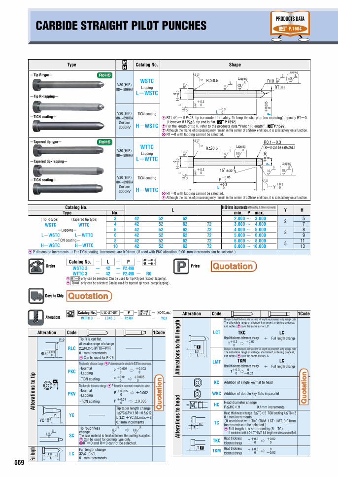
CARBIDE STRAIGHT PILOT PUNCHES WITH KEY GROOVESCARBIDE STRAIGHT PILOT PUNCHES
Type ~
Catalog No. Shape
-Tip R type-
-Tip R・lapping-
-TiCN coating-
V30(HIP) 88~89HRA
WSTC Lapping
L-WSTC
�RT(※) If P<8, tip is rounded for safety. To keep the sharp tip(no rounding), specify RT=0. (However if f P≧8, tip end is flat. P.1592) For the length of tip R, refer to the products data “Punch R length”. P.1592 Although the marks of processing may remain in the center of a Shank end face, it is satisfactory on a function. RT=0 with lapping cannot be selected.
V30(HIP) 88~89HRA
Surface 3000HV
TiCN coating
H-WSTC
-Tapered tip type-
-Tapered tip・lapping-
-TiCN coating-
V30(HIP) 88~89HRA
WTTC Lapping
L-WTTC
RT=0 with lapping cannot be selected. Although the marks of processing may remain in the center of a Shank end face, it is satisfactory on a function.
V30(HIP) 88~89HRA
Surface 3000HV
TiCN coating
H-WTTC
Catalog No. L 0.001mm increments(With coating, 0.01mm increments)Y HType No. min. P max.
(Tip R type) (Tapered tip type)WSTC WTTC
-Lapping- L-WSTC L-WTTC
-TiCN coating- H-WSTC H-WTTC
3 42 52 62 2.000 ~ 3.000 2 54 42 52 62 72 3.000 ~ 4.000 75 42 52 62 72 4.000 ~ 5.000 3 86 42 52 62 72 5.000 ~ 6.000 98 42 52 62 72 6.000 ~ 8.000 5 1110 42 52 62 72 8.000 ~ 10.000 13
P dimension increments For TiCN coating, increments are 0.01mm.(If used with PKC alteration, 0.001mm increments can be selected.)
0.08GL
0.08GL
H-
0.2
0
5
L P
R≦0.5 R106.3 0.2
G
1.6G
+0.30
+0.30
1.6G
+0.
005
0
0.2G
RT(※)
Lapping
Lapping
0.08GL
G
HG
1.6
-0.
20
+0.305
6.3
F 0+0.05
0.2
P
G
R≦0.5
1.6
+0.
005
0
R0.1~0.3
+0.30L Y
+0.30
1.6G
15°±30́ 0.2G
0.08GL
Lapping
(R=0 can be selected.)Lapping
OrderCatalog No. - L - P - RT=0
R =0
WSTC 3 - 42 - P2.490WTTC 3 - 42 - P2.490 - R0
RT=0 only can be selected: Can be used for tip R types(except lapping). R=0 only can be selected: Can be used for tapered tip types(except lapping).
Days to Ship
Price
Alteration Code 1Code
Alte
ratio
ns to
tip
RLC
Tip R is cut flat. Allowable range of change 2≦RLC<√P(10-P/4) 0.1mm increments Can be used for P<8.
-
PKC
Tip diameter tolerance change P dimension can be selected in 0.001mm increments.・Normal ・Lapping
・TiCN coating
PKV
Tip diameter tolerance change P dimension increment remains the same.・Normal ・Lapping
・TiCN coating
YC -
Tip taper length change 1≦YC≦P×1.86-0.3≦12 L(LC)+YC≦Lmax.+8 0.1mm increments
SC
Tip roughness changeThe base material is finished before the coating is applied. Can be used for coating type only. RT=0 and R=0 cannot be selected.
Full le
ngth
LCFull length change 32≦LC<L 0.1mm increments
P +0.0050 ⇨ +0.003
0
P +0.010 ⇨ +0.005
0
P +0.0050 ⇨ ±0.002
P +0.010 ⇨ ±0.005
P
LCL
RLC 0+0.3
R10
YC+0.30
Y
┄
Alteration Code 1Code
Alte
ratio
ns to
full
leng
th
LCT
Changes to head thickness tolerance and full length are processed using a single code. The allowable range of change, increment, ordering process, and notes()are the same as for LC.
TKC Head thickness tolerance change
T+0.30 ⇨ +0.02
0
LC + Full length change
LMT
Changes to head thickness tolerance and full length are processed using a single code. The allowable range of change, increment, ordering process, and notes()are the same as for LC.
TKM Head thickness tolerance change
T+0.30 ⇨ 0
-0.02
LC + Full length change
Alte
ratio
ns to
hea
d
KC Addition of single key flat to head
WKC Addition of double key flats in parallel
HC Head diameter change P≦HC<H 0.1mm increments
TC
Head thickness change 2≦TC<5 TiCN coating 4≦TC<5 0.1mm increments
(If combined with TKC・TKM・LCT・LMT, 0.01mm increments can be selected.) �Full length L is shortened by(5-TC).
If combined with LC・LCT・LMT, full length remains as specified.
TKC Head thickness tolerance change
T +0.30 ⇨ +0.02
0
TKM Head thickness tolerance change
T +0.30 ⇨ 0
-0.02
LCL
T ┄
TTC
T ┄
H HC
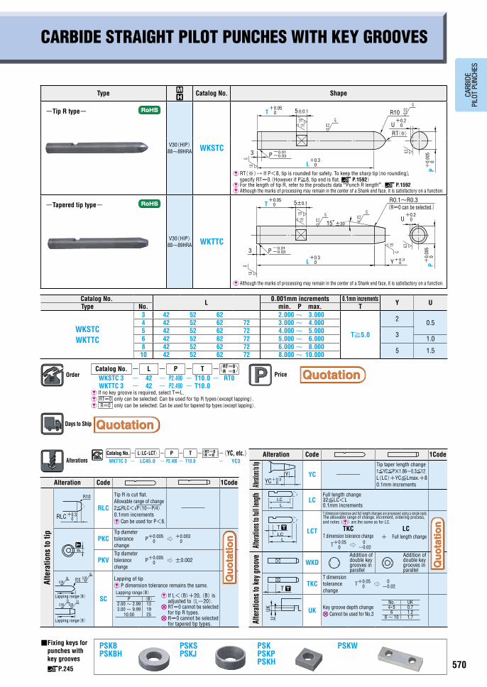
Type ~
Catalog No. Shape
-Tip R type-
V30(HIP) 88~89HRA WKSTC
�RT(※) If P<8, tip is rounded for safety. To keep the sharp tip(no rounding), specify RT=0.(However if P≧8, tip end is flat. P.1592)
For the length of tip R, refer to the products data “Punch R length”. P.1592 Although the marks of processing may remain in the center of a Shank end face, it is satisfactory on a function.
-Tapered tip type-
V30(HIP) 88~89HRA WKTTC
Although the marks of processing may remain in the center of a Shank end face, it is satisfactory on a function.
Catalog No. L 0.001mm increments 0.1mm increments Y UType No. min. P max. T
WKSTC WKTTC
3 42 52 62 2.000 ~ 3.000
T≧5.0
2 0.54 42 52 62 72 3.000 ~ 4.0005 42 52 62 72 4.000 ~ 5.000 36 42 52 62 72 5.000 ~ 6.000 1.08 42 52 62 72 6.000 ~ 8.000 5 1.510 42 52 62 72 8.000 ~ 10.000
T
3
L
U0.2G
R10 0.2G
1.6G
+0.050
P-0.03-0.01
+0.30
+0.20
+0.
005
P0
5±0.1
1.6
6.3
RT(※)
1.6
OrderCatalog No. - L - P - T - RT=0
R =0
WKSTC 3 - 42 - P2.490 - T10.0 - RT0WKTTC 3 - 42 - P2.490 - T10.0
If no key groove is required, select T=L. RT=0 only can be selected: Can be used for tip R types(except lapping). R=0 only can be selected: Can be used for tapered tip types(except lapping).
Days to Ship
Price
Alteration Code 1Code
Alte
ratio
ns to
tip
RLC
Tip R is cut flat. Allowable range of change 2≦RLC<√P(10-P/4) 0.1mm increments Can be used for P<8.
-
PKCTip diameter tolerance change
P+0.0050 ⇨ +0.003
0
PKVTip diameter tolerance change
P+0.0050 ⇨ ±0.002
SC
Lapping of tip P dimension tolerance remains the same.
�If L<(B)+20, (B) is adjusted to (L-20).
RT=0 cannot be selected for tip R types.
R=0 cannot be selected for tapered tip types.
Alteration Code 1Code
Alterati
ons to t
ip
YC -
Tip taper length change 1≦YC≦P×1.86-0.3≦12 L(LC)+YC≦Lmax.+8 0.1mm increments
Altera
tions
to fu
ll len
gth LCFull length change 32≦LC<L 0.1mm increments
LCT
T dimension tolerance and full length changes are processed using a single code. The allowable range of change, increment, ordering process, and notes () are the same as for LC.
TKC T dimension tolerance change
T+0.050 ⇨ 0
-0.02
LC + Full length change
Alte
ratio
ns to
key g
roov
e
WKDAddition of double key grooves in parallel
Addition of double key grooves in parallel
TKCT dimension tolerance change
T+0.050 ⇨ 0
-0.02
UK Key groove depth change �Cannot be used for No.3
■ Fixing keys for punches with key grooves
P.245
PSKB PSKBH
PSKS PSKJ
PSK PSKP PSKH
PSKW
Lapping range(B)P (B)
2.00 ~ 2.99 3.00 ~ 9.99
10.00
13 19 25
No. UK4・5 0.7
6 1.28 ~ 10 1.7
LCL
T T
UKU
YC+0.30
Y
T T
LLC
P
0.08GL 0.08
GL
0.08GL
0.08GL
R10
Lapping range(B)
RLC 0+0.3
R10
Lapping range(B)
┄
PRODUCTS DATA
P.1604
P
LCL
RLC 0+0.3
R10
YC+0.30
Y
┄P
LCL
RLC 0+0.3
R10
YC+0.30
Y
┄P
LCL
RLC 0+0.3
R10
YC+0.30
Y
┄
AlterationsCatalog No. - L(LC・LCT・LMT)- P - RT=0
R =0 -(HC・TC, etc.)WTTC 3 - LC45.0 - P2.490 - YC3
LCL
T ┄
TTC
T ┄
H HC
LCL
T ┄
TTC
T ┄
H HC
0.08GL 0.2
G GL0.08⇨
3
L Y
U
R0.1~R0.3
15°±30́0.2
G 0.2G
1.6
1.6G
+0.30
+0.30
+0.20
-0.01-0.03P
0+
0.00
5P
1.6
+0.05T 0 5±0.1
G
6.3
(R=0 can be selected.)
1.6
AlterationsCatalog No.- L(LC・LCT)- P - T - RT=0
R =0 -(YC, etc.)WKTTC 3 - LC45.0 - P2.490 - T10.0 - YC3
569 570
CARB
IDE
PILO
T PU
NCHE
S
CARBIDE STRAIGHT PILOT PUNCHES WITH KEY GROOVESCARBIDE STRAIGHT PILOT PUNCHES
Type ~
Catalog No. Shape
-Tip R type-
-Tip R・lapping-
-TiCN coating-
V30(HIP) 88~89HRA
WSTC Lapping
L-WSTC
�RT(※) If P<8, tip is rounded for safety. To keep the sharp tip(no rounding), specify RT=0. (However if f P≧8, tip end is flat. P.1592) For the length of tip R, refer to the products data “Punch R length”. P.1592 Although the marks of processing may remain in the center of a Shank end face, it is satisfactory on a function. RT=0 with lapping cannot be selected.
V30(HIP) 88~89HRA
Surface 3000HV
TiCN coating
H-WSTC
-Tapered tip type-
-Tapered tip・lapping-
-TiCN coating-
V30(HIP) 88~89HRA
WTTC Lapping
L-WTTC
RT=0 with lapping cannot be selected. Although the marks of processing may remain in the center of a Shank end face, it is satisfactory on a function.
V30(HIP) 88~89HRA
Surface 3000HV
TiCN coating
H-WTTC
Catalog No. L 0.001mm increments(With coating, 0.01mm increments)Y HType No. min. P max.
(Tip R type) (Tapered tip type)WSTC WTTC
-Lapping- L-WSTC L-WTTC
-TiCN coating- H-WSTC H-WTTC
3 42 52 62 2.000 ~ 3.000 2 54 42 52 62 72 3.000 ~ 4.000 75 42 52 62 72 4.000 ~ 5.000 3 86 42 52 62 72 5.000 ~ 6.000 98 42 52 62 72 6.000 ~ 8.000 5 1110 42 52 62 72 8.000 ~ 10.000 13
P dimension increments For TiCN coating, increments are 0.01mm.(If used with PKC alteration, 0.001mm increments can be selected.)
0.08GL
0.08GL
H-
0.2
0
5
L P
R≦0.5 R106.3 0.2
G
1.6G
+0.30
+0.30
1.6G
+0.
005
0
0.2G
RT(※)
Lapping
Lapping
0.08GL
G
HG
1.6
-0.
20
+0.305
6.3
F 0+0.05
0.2
P
G
R≦0.5
1.6
+0.
005
0
R0.1~0.3
+0.30L Y
+0.30
1.6G
15°±30́ 0.2G
0.08GL
Lapping
(R=0 can be selected.)Lapping
OrderCatalog No. - L - P - RT=0
R =0
WSTC 3 - 42 - P2.490WTTC 3 - 42 - P2.490 - R0
RT=0 only can be selected: Can be used for tip R types(except lapping). R=0 only can be selected: Can be used for tapered tip types(except lapping).
Days to Ship
Price
Alteration Code 1Code
Alte
ratio
ns to
tip
RLC
Tip R is cut flat. Allowable range of change 2≦RLC<√P(10-P/4) 0.1mm increments Can be used for P<8.
-
PKC
Tip diameter tolerance change P dimension can be selected in 0.001mm increments.・Normal ・Lapping
・TiCN coating
PKV
Tip diameter tolerance change P dimension increment remains the same.・Normal ・Lapping
・TiCN coating
YC -
Tip taper length change 1≦YC≦P×1.86-0.3≦12 L(LC)+YC≦Lmax.+8 0.1mm increments
SC
Tip roughness changeThe base material is finished before the coating is applied. Can be used for coating type only. RT=0 and R=0 cannot be selected.
Full le
ngth
LCFull length change 32≦LC<L 0.1mm increments
P +0.0050 ⇨ +0.003
0
P +0.010 ⇨ +0.005
0
P +0.0050 ⇨ ±0.002
P +0.010 ⇨ ±0.005
P
LCL
RLC 0+0.3
R10
YC+0.30
Y
┄
Alteration Code 1Code
Alte
ratio
ns to
full
leng
th
LCT
Changes to head thickness tolerance and full length are processed using a single code. The allowable range of change, increment, ordering process, and notes()are the same as for LC.
TKC Head thickness tolerance change
T+0.30 ⇨ +0.02
0
LC + Full length change
LMT
Changes to head thickness tolerance and full length are processed using a single code. The allowable range of change, increment, ordering process, and notes()are the same as for LC.
TKM Head thickness tolerance change
T+0.30 ⇨ 0
-0.02
LC + Full length change
Alte
ratio
ns to
hea
d
KC Addition of single key flat to head
WKC Addition of double key flats in parallel
HC Head diameter change P≦HC<H 0.1mm increments
TC
Head thickness change 2≦TC<5 TiCN coating 4≦TC<5 0.1mm increments
(If combined with TKC・TKM・LCT・LMT, 0.01mm increments can be selected.) �Full length L is shortened by(5-TC).
If combined with LC・LCT・LMT, full length remains as specified.
TKC Head thickness tolerance change
T +0.30 ⇨ +0.02
0
TKM Head thickness tolerance change
T +0.30 ⇨ 0
-0.02
LCL
T ┄
TTC
T ┄
H HC
Type ~
Catalog No. Shape
-Tip R type-
V30(HIP) 88~89HRA WKSTC
�RT(※) If P<8, tip is rounded for safety. To keep the sharp tip(no rounding), specify RT=0.(However if P≧8, tip end is flat. P.1592)
For the length of tip R, refer to the products data “Punch R length”. P.1592 Although the marks of processing may remain in the center of a Shank end face, it is satisfactory on a function.
-Tapered tip type-
V30(HIP) 88~89HRA WKTTC
Although the marks of processing may remain in the center of a Shank end face, it is satisfactory on a function.
Catalog No. L 0.001mm increments 0.1mm increments Y UType No. min. P max. T
WKSTC WKTTC
3 42 52 62 2.000 ~ 3.000
T≧5.0
2 0.54 42 52 62 72 3.000 ~ 4.0005 42 52 62 72 4.000 ~ 5.000 36 42 52 62 72 5.000 ~ 6.000 1.08 42 52 62 72 6.000 ~ 8.000 5 1.510 42 52 62 72 8.000 ~ 10.000
T
3
L
U0.2G
R10 0.2G
1.6G
+0.050
P-0.03-0.01
+0.30
+0.20
+0.
005
P0
5±0.1
1.6
6.3
RT(※)
1.6
OrderCatalog No. - L - P - T - RT=0
R =0
WKSTC 3 - 42 - P2.490 - T10.0 - RT0WKTTC 3 - 42 - P2.490 - T10.0
If no key groove is required, select T=L. RT=0 only can be selected: Can be used for tip R types(except lapping). R=0 only can be selected: Can be used for tapered tip types(except lapping).
Days to Ship
Price
Alteration Code 1Code
Alte
ratio
ns to
tip
RLC
Tip R is cut flat. Allowable range of change 2≦RLC<√P(10-P/4) 0.1mm increments Can be used for P<8.
-
PKCTip diameter tolerance change
P+0.0050 ⇨ +0.003
0
PKVTip diameter tolerance change
P+0.0050 ⇨ ±0.002
SC
Lapping of tip P dimension tolerance remains the same.
�If L<(B)+20, (B) is adjusted to (L-20).
RT=0 cannot be selected for tip R types.
R=0 cannot be selected for tapered tip types.
Alteration Code 1Code
Alterati
ons to t
ip
YC -
Tip taper length change 1≦YC≦P×1.86-0.3≦12 L(LC)+YC≦Lmax.+8 0.1mm increments
Altera
tions
to fu
ll len
gth LCFull length change 32≦LC<L 0.1mm increments
LCT
T dimension tolerance and full length changes are processed using a single code. The allowable range of change, increment, ordering process, and notes () are the same as for LC.
TKC T dimension tolerance change
T+0.050 ⇨ 0
-0.02
LC + Full length change
Alte
ratio
ns to
key g
roov
e
WKDAddition of double key grooves in parallel
Addition of double key grooves in parallel
TKCT dimension tolerance change
T+0.050 ⇨ 0
-0.02
UK Key groove depth change �Cannot be used for No.3
■ Fixing keys for punches with key grooves
P.245
PSKB PSKBH
PSKS PSKJ
PSK PSKP PSKH
PSKW
Lapping range(B)P (B)
2.00 ~ 2.99 3.00 ~ 9.99
10.00
13 19 25
No. UK4・5 0.7
6 1.28 ~ 10 1.7
LCL
T T
UKU
YC+0.30
Y
T T
LLC
P
0.08GL 0.08
GL
0.08GL
0.08GL
R10
Lapping range(B)
RLC 0+0.3
R10
Lapping range(B)
┄
PRODUCTS DATA
P.1604
P
LCL
RLC 0+0.3
R10
YC+0.30
Y
┄P
LCL
RLC 0+0.3
R10
YC+0.30
Y
┄P
LCL
RLC 0+0.3
R10
YC+0.30
Y
┄
AlterationsCatalog No. - L(LC・LCT・LMT)- P - RT=0
R =0 -(HC・TC, etc.)WTTC 3 - LC45.0 - P2.490 - YC3
LCL
T ┄
TTC
T ┄
H HC
LCL
T ┄
TTC
T ┄
H HC
0.08GL 0.2
G GL0.08⇨
3
L Y
U
R0.1~R0.3
15°±30́0.2
G 0.2G
1.6
1.6G
+0.30
+0.30
+0.20
-0.01-0.03P
0+
0.00
5P
1.6
+0.05T 0 5±0.1
G
6.3
(R=0 can be selected.)
1.6
AlterationsCatalog No.- L(LC・LCT)- P - T - RT=0
R =0 -(YC, etc.)WKTTC 3 - LC45.0 - P2.490 - T10.0 - YC3
571 572
CARB
IDE
PILO
T PU
NCHE
S
Type Shank diameter D tolerance
~
Catalog No. Shape
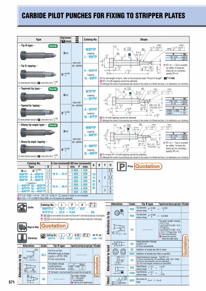
-Tip R type-
-Tip R・lapping-
For shank diameter tolerance D , select either m5 or +0.0050 .
Dm5
V30(HIP) 88~89HRA
WSPTP Lapping
L-WSPTP
D+0.0050
A-WSPTP Lapping
AL-WSPTP
RT(※) Tip is rounded for safety. To keep the sharp tip(no rounding), specify RT=0.
For the length of tip R, refer to the products data “Punch R length”. P.1592 RT=0 with lapping cannot be selected. Although the marks of processing may remain in the center of a Shank end face, it is satisfactory on a function.
-Tapered tip type-
-Tapered tip・lapping-
For shank diameter tolerance D , select either m5 or +0.0050 .
Dm5
V30(HIP) 88~89HRA
WTPTP Lapping
L-WTPTP
R=0 with lapping cannot be selected. Although the marks of processing may remain in the center of a Shank end face, it is satisfactory on a function.
D+0.0050
A-WTPTP Lapping
AL-WTPTP
-Sharp tip angle type-
-Sharp tip angle・lapping-
For shank diameter tolerance D , select either m5 or +0.005
0 .
Dm5
V30(HIP) 88~89HRA
WAPTP Lapping
L-WAPTP
R=0 and RT=0 with lapping cannot be selected. Although the marks of processing may remain in the center of a Shank end face, it is satisfactory on a function.
D+0.0050
A-WAPTP Lapping
AL-WAPTP
Catalog No. 0.1mm increments 0.001mm increments A B Y HType D L min. P max.(Dm5) (D+0.005
0 ) WSPTP A-WSPTP WTPTP A-WTPTP WAPTP A-WAPTP
-Lapping- L-WSPTP AL-WSPTP L-WTPTP AL-WTPTP L-WAPTP AL-WAPTP
1.610.0~ 32.0
0.800~1.599(10)
15 20 25 30
42
2.62.0 1.000~1.990 32.5 1.000~2.490 3.53
10.0~ 40.0
1.000~2.990 54 2.000~3.990 75 2.000~4.990
38
6 2.500~5.990 9 P>D-0.03 ℓ=0 If P>D-0.03, D -0.01
-0.03(press-in lead)is not included. A(10) P<2.000 If P≧2.000, A=10 cannot be selected.
OrderCatalog No.- L - P - A - RT=0
R =0
WAPTP 6 - 29.0 - P4.071- A15WTPTP 6 - 20.0 - P5.020 - R0 RT=0 only can be selected: Can be used for tip R types with P<8 and sharp tip angle types.(Except lapping)
R=0 only can be selected: Can be used for tapered tip types and sharp tip angle types.(Except lapping)
Days to Ship
AlterationsCatalog No.- L - P -A(AC)- RT=0
R =0 -(HC・TC, etc.)WAPTP 6 - 20.0 - P5.020 - AC18 - HC6-PKC
H
3
D ┄
P
Ra
D R10
-0.
2
B
-0.03
+0.3
-0.01
+0.
005
0
0
+0.30
0
6.3
1.6G
1.6G
+0.30
0.4G
L
R20.2 G0.08 GL 0.2 0.08 GLG
ℓ=1
RT (※)
LappingLapping
+0.3
1.6G
3 0
+0.30
0+0.3
0+0.3
H-
0.2
0
6.3
1.6
G0.4
RaG
D ┄
B
P+
0.00
50
Y
1.6G
G±30́
L
F+0.05
0
0.2 G 0.08 GL0.2 0.08 GLD-0.03-0.01 R2
G
R0.1~0.3
ℓ=1
(R=0 can be selected.)
LappingLapping
H-
0.2
0
D-0.03-0.01 R2
+0.3
1.6G
3 0
0+0.3
0+0.3
6.3
1.6
G0.4
RaG
D ┄
B
P+
0.00
50
A°±30́
L
F+0.05
0
RT(※)
0.2 G 0.08 GL0.2 G 0.08 GL
R0.1~0.3
ℓ=1
(R=0 can be selected.)
LappingLapping
Type Shank diameter D tolerance
~
Catalog No. Shape
-Tip R type-
For shank diameter tolerance D , select either m5 or +0.0050 .
Dm5
V30(HIP) 88~89HRA
Surface 3000HV
H-WSPTP �RT(※) Tip is rounded
for safety. To keep the sharp tip(no rounding), specify RT=0.
D+0.0050 AH-WSPTP
For the length of tip R, refer to the products data “Punch R length”. P.1592 Although the marks of processing may remain in the center of a Shank end face, it is satisfactory on a function.
-Tapered tip type-
For shank diameter tolerance D , select either m5 or +0.0050 .
Dm5
V30(HIP) 88~89HRA
Surface 3000HV
H-WTPTP
Although the marks of processing may remain in the center of a Shank end face, it is satisfactory on a function.
D+0.0050 AH-WTPTP
-Sharp tip angle type-
For shank diameter tolerance D , select either m5 or +0.0050 .
Dm5
V30(HIP) 88~89HRA
Surface 3000HV
H-WAPTP
Although the marks of processing may remain in the center of a Shank end face, it is satisfactory on a function.
D+0.0050 AH-WAPTP
Catalog No. 0.1mm increments 0.01mm increments A B Y HType D L min.P max.
(Dm5) (D +0.0050 )
H-WSPTP AH-WSPTP H-WTPTP AH-WTPTP H-WAPTP AH-WAPTP
1.610.0~ 32.0
1.00~ 1.59(10)
15 20 25 30
42
2.62.0 1.00~ 1.99 32.5 1.00~ 2.49 3.53
10.0~ 40.0
1.00~ 2.99 54 2.00~ 3.99 75 2.00~ 4.99 3 86 2.50~ 5.99 9
P>D-0.03 ℓ=0 If P>D-0.03, D -0.01-0.03(press-in lead)is not included.
An extremely thin coating layer is also formed on the shank. A(10) P<2.00 If P≧2.00, A=10 cannot be selected. If used with PKC alteration, P dimension can be selected in 0.001mm increments.
OrderCatalog No. - L - P - A - RT=0
R =0
H-WAPTP 6 - 29.0 - P4.00 - A15 - R0-RT0H-WSPTP 6 - 20.0 - P5.02 RT=0 only can be selected: Can be used for tip R types with P<8 and sharp tip angle types.(Except lapping) R=0 only can be selected: Can be used for tapered tip types and sharp tip angle types.(Except lapping)
AlterationsCatalog No.- L - P - A(AC)- RT=0
R =0 -(HC・TC, etc.)H-WAPTP 6 - 20.0 - P5.02 - AC18 -HC7
CARBIDE PILOT PUNCHES FOR FIXING TO STRIPPER PLATES
D Ra1.6~2.5 ≦0.2
3~6 ≦0.5
D Ra1.6~2.5 ≦0.2
3~6 ≦0.5
Price
Alteration Code Tip R type Tapered tip and sharp tip angle types 1Code
Alte
ratio
ns to
tip RLC
Tip R is cut flat. Allowable range of change 2≦RLC<√P(10-P/4) 0.1mm increments
-
BC
Tip length change 2≦BC≦Bmax. 0.1mm increments Full length L must be at least 8mm longer than tip length BC.
AC -Tip angle change 15°<AC≦45° 1°increments Cannot be used for tapered tip types.
BC B
RLC 0+0.3
R10
L
AC
P Bmax.0.800~1.999 2.000~
15 21
Alteration Code Tip R type Tapered tip and sharp tip angle types 1Code
Alte
ratio
ns to
tip
PKC Tip diameter tolerance change
P+0.0050 ⇨ +0.003
0
PKV Tip diameter tolerance change
P+0.0050 ⇨ ±0.002
YC -
Tip taper length change ・If P<2.0, 1≦YC≦P×2.83-0.3 ・If P≧2.0, 1≦YC≦P×1.86-0.3 L(LC)+YC≦Lmax.+8 0.1mm increments �Cannot be used for
sharp tip angle types.
Alte
ratio
ns to
hea
d HCHead diameter change D≦HC<H 0.1mm increments
KC Addition of single key flat to head
WKC Addition of double key flats in parallel
TCHead thickness change 2≦TC<3 0.1mm increments(If combined with TKC・TKM, 0.01mm increments can be selected.) The full length remains as specified.
TKC Head thickness tolerance change T+0.3
0 ⇨ +0.020
TKM Head thickness tolerance change T+0.3
0 ⇨ 0-0.02
Othe
rs
NDC No press-in lead
ℓ=1 ⇨ ℓ=0
P
TTC
HCH
T ┄
-0.03-0.01
Dℓ
YC+0.30
Y
┄
CARBIDE PILOT PUNCHES FOR FIXING TO STRIPPER PLATES -TiCN COATING-
PRODUCTS DATA
P.1604
D Ra1.6~ 2.5 ≦0.2
3~ 6 ≦0.5
D Ra1.6~ 2.5 ≦0.2
3~ 6 ≦0.5
P G1.00~ 1.99 10°2.00~ 15°
D Ra1.6~ 2.5 ≦0.2
3~ 6 ≦0.5
0
1.6
+0.3HG
3
-0.
20
+0.3 0+0.30
1.6
6.3
G
G0.4
Ra
D ┄
0.2
+0.
01PB
0
R2G
-0.01-0.03D
R10
L
0.2G
ℓ=1RT(※)
Price
Alteration Code Tip R type Tapered tip and sharp tip angle types 1Code
Alte
ratio
ns to
tip
RLC
Tip R is cut flat. Allowable range of change 2≦RLC<√P(10-P/4) 0.1mm increments
-
BCTip length change 2≦BC≦Bmax.≦L/2 0.1mm increments Full length L must be at least 8mm longer than tip length BC.
PKCTip diameter tolerance change
P+0.010 ⇨ +0.005
0
P dimension can be selected in 0.001mm increments.
PKVTip diameter tolerance change
P+0.010 ⇨ ±0.005
P dimension increment remains the same.
SCTip roughness change
⇨
The base material is finished before the coating is applied. R=0 and RT=0 cannot be selected.
AC -Tip angle change 15°<AC≦45° 1° increments Cannot be used for tapered tip types.
P Bmax.1.00~ 1.99 2.00~
15 16
BC B
0.08GL
P
RLC 0+0.3
R10
L
AC
┄
Alteration Code Tip R type Tapered tip and sharp tip angle types 1Code
Alte
ratio
ns to
tip
YC -
Tip taper length change ・If P<2.0, 1≦YC≦P×2.83-0.3 ・If P≧2.0, 1≦YC≦P×1.86-0.3 L(LC)+YC≦Lmax.+8 0.1mm increments �Cannot be used for
sharp tip angle types.
Alte
ratio
ns to
hea
d
HCHead diameter change D≦HC<H 0.1mm increments
KC Addition of single key flat to head
WKC Addition of double key flats in parallel
TCHead thickness change 2≦TC<3 0.1mm increments(If combined with TKC・TKM, 0.01mm increments can be selected.) The full length remains as specified.
TKC Head thickness tolerance change T +0.3
0 ⇨ +0.020
TKM Head thickness tolerance change T +0.3
0 ⇨ 0-0.02
Othe
rs
NDC No press-in lead
ℓ=1 ⇨ ℓ=0
TTC
-0.03-0.01
Dℓ
H HC
T ┄
YC+0.30
Y
0.2G
0.08GL
P G0.800~1.999 10°2.000~ 15°
D Ra1.6~2.5 ≦0.2
3~6 ≦0.5
Days to Ship
-0.
2
+0.3
1.6G
H
3
+0.3L 0
+0.30
0
G±30́
0
6.30.4 D
┄GG Ra
1.6 D-0.03
+0.
01G
Y
B 1.6 P0
R0.1~ 0.3(R=0 can be selected.)G
0.2R2
-0.01
F+0.05
0
+0.30
0.2G
ℓ=1
-0.
2
+0.3
1.6G
H
3
+0.3L 0
+0.30
0A°±30́
0
6.30.4 D
┄GG
Ra
1.6 D-0.03
+0.
01
B P0
R0.1~0.3
G0.2
R2
-0.01
F+0.050
0.2G
RT(※)
ℓ=1 (R=0 can be selected.)
�RT(※)Tip is rounded for safety. To keep the sharp tip(no rounding), specify RT=0.
�RT(※) Tip is rounded for safety. To keep the sharp tip(no rounding), specify RT=0.
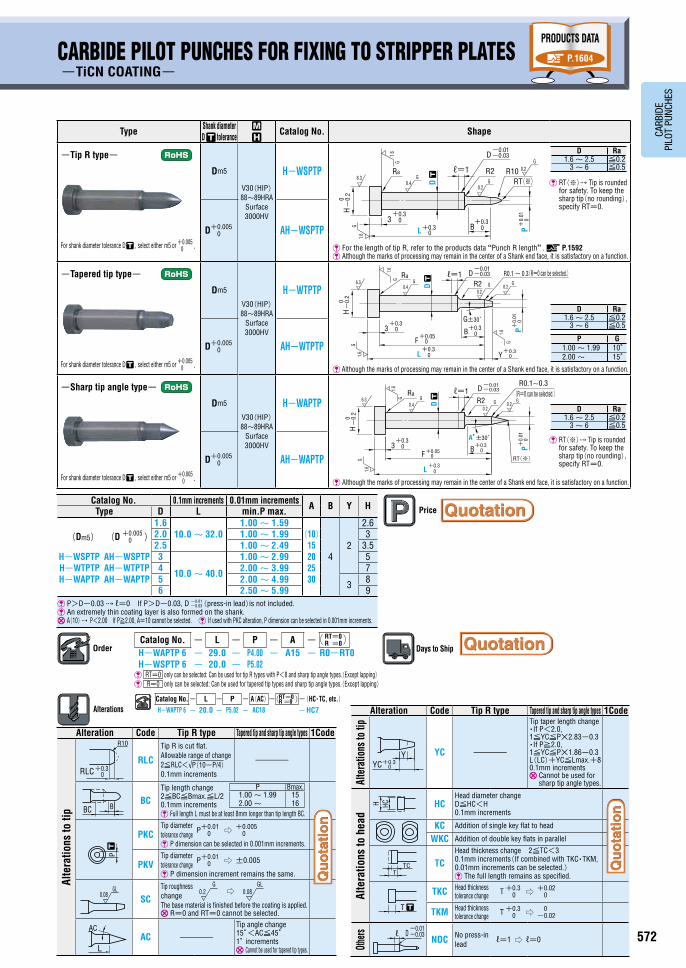
571 572
CARB
IDE
PILO
T PU
NCHE
S
Type Shank diameter D tolerance
~
Catalog No. Shape
-Tip R type-
-Tip R・lapping-
For shank diameter tolerance D , select either m5 or +0.0050 .
Dm5
V30(HIP) 88~89HRA
WSPTP Lapping
L-WSPTP
D+0.0050
A-WSPTP Lapping
AL-WSPTP
RT(※) Tip is rounded for safety. To keep the sharp tip(no rounding), specify RT=0.
For the length of tip R, refer to the products data “Punch R length”. P.1592 RT=0 with lapping cannot be selected. Although the marks of processing may remain in the center of a Shank end face, it is satisfactory on a function.
-Tapered tip type-
-Tapered tip・lapping-
For shank diameter tolerance D , select either m5 or +0.0050 .
Dm5
V30(HIP) 88~89HRA
WTPTP Lapping
L-WTPTP
R=0 with lapping cannot be selected. Although the marks of processing may remain in the center of a Shank end face, it is satisfactory on a function.
D+0.0050
A-WTPTP Lapping
AL-WTPTP
-Sharp tip angle type-
-Sharp tip angle・lapping-
For shank diameter tolerance D , select either m5 or +0.005
0 .
Dm5
V30(HIP) 88~89HRA
WAPTP Lapping
L-WAPTP
R=0 and RT=0 with lapping cannot be selected. Although the marks of processing may remain in the center of a Shank end face, it is satisfactory on a function.
D+0.0050
A-WAPTP Lapping
AL-WAPTP
Catalog No. 0.1mm increments 0.001mm increments A B Y HType D L min. P max.(Dm5) (D+0.005
0 ) WSPTP A-WSPTP WTPTP A-WTPTP WAPTP A-WAPTP
-Lapping- L-WSPTP AL-WSPTP L-WTPTP AL-WTPTP L-WAPTP AL-WAPTP
1.610.0~ 32.0
0.800~1.599(10)
15 20 25 30
42
2.62.0 1.000~1.990 32.5 1.000~2.490 3.53
10.0~ 40.0
1.000~2.990 54 2.000~3.990 75 2.000~4.990
38
6 2.500~5.990 9 P>D-0.03 ℓ=0 If P>D-0.03, D -0.01
-0.03(press-in lead)is not included. A(10) P<2.000 If P≧2.000, A=10 cannot be selected.
OrderCatalog No.- L - P - A - RT=0
R =0
WAPTP 6 - 29.0 - P4.071- A15WTPTP 6 - 20.0 - P5.020 - R0 RT=0 only can be selected: Can be used for tip R types with P<8 and sharp tip angle types.(Except lapping)
R=0 only can be selected: Can be used for tapered tip types and sharp tip angle types.(Except lapping)
Days to Ship
AlterationsCatalog No.- L - P -A(AC)- RT=0
R =0 -(HC・TC, etc.)WAPTP 6 - 20.0 - P5.020 - AC18 - HC6-PKC
H
3
D ┄
P
Ra
D R10
-0.
2
B
-0.03
+0.3
-0.01
+0.
005
0
0
+0.30
0
6.3
1.6G
1.6G
+0.30
0.4G
L
R20.2 G0.08 GL 0.2 0.08 GLG
ℓ=1
RT (※)
LappingLapping
+0.3
1.6G
3 0
+0.30
0+0.3
0+0.3
H-
0.2
0
6.3
1.6
G0.4
RaG
D ┄
B
P+
0.00
50
Y
1.6G
G±30́
L
F+0.05
0
0.2 G 0.08 GL0.2 0.08 GLD-0.03-0.01 R2
G
R0.1~0.3
ℓ=1
(R=0 can be selected.)
LappingLapping
H-
0.2
0
D-0.03-0.01 R2
+0.3
1.6G
3 0
0+0.3
0+0.3
6.3
1.6
G0.4
RaG
D ┄
B
P+
0.00
50
A°±30́
L
F+0.05
0
RT(※)
0.2 G 0.08 GL0.2 G 0.08 GL
R0.1~0.3
ℓ=1
(R=0 can be selected.)
LappingLapping
Type Shank diameter D tolerance
~
Catalog No. Shape
-Tip R type-
For shank diameter tolerance D , select either m5 or +0.0050 .
Dm5
V30(HIP) 88~89HRA
Surface 3000HV
H-WSPTP �RT(※) Tip is rounded
for safety. To keep the sharp tip(no rounding), specify RT=0.
D+0.0050 AH-WSPTP
For the length of tip R, refer to the products data “Punch R length”. P.1592 Although the marks of processing may remain in the center of a Shank end face, it is satisfactory on a function.
-Tapered tip type-
For shank diameter tolerance D , select either m5 or +0.0050 .
Dm5
V30(HIP) 88~89HRA
Surface 3000HV
H-WTPTP
Although the marks of processing may remain in the center of a Shank end face, it is satisfactory on a function.
D+0.0050 AH-WTPTP
-Sharp tip angle type-
For shank diameter tolerance D , select either m5 or +0.0050 .
Dm5
V30(HIP) 88~89HRA
Surface 3000HV
H-WAPTP
Although the marks of processing may remain in the center of a Shank end face, it is satisfactory on a function.
D+0.0050 AH-WAPTP
Catalog No. 0.1mm increments 0.01mm increments A B Y HType D L min.P max.
(Dm5) (D +0.0050 )
H-WSPTP AH-WSPTP H-WTPTP AH-WTPTP H-WAPTP AH-WAPTP
1.610.0~ 32.0
1.00~ 1.59(10)
15 20 25 30
42
2.62.0 1.00~ 1.99 32.5 1.00~ 2.49 3.53
10.0~ 40.0
1.00~ 2.99 54 2.00~ 3.99 75 2.00~ 4.99 3 86 2.50~ 5.99 9
P>D-0.03 ℓ=0 If P>D-0.03, D -0.01-0.03(press-in lead)is not included.
An extremely thin coating layer is also formed on the shank. A(10) P<2.00 If P≧2.00, A=10 cannot be selected. If used with PKC alteration, P dimension can be selected in 0.001mm increments.
OrderCatalog No. - L - P - A - RT=0
R =0
H-WAPTP 6 - 29.0 - P4.00 - A15 - R0-RT0H-WSPTP 6 - 20.0 - P5.02 RT=0 only can be selected: Can be used for tip R types with P<8 and sharp tip angle types.(Except lapping) R=0 only can be selected: Can be used for tapered tip types and sharp tip angle types.(Except lapping)
AlterationsCatalog No.- L - P - A(AC)- RT=0
R =0 -(HC・TC, etc.)H-WAPTP 6 - 20.0 - P5.02 - AC18 -HC7
CARBIDE PILOT PUNCHES FOR FIXING TO STRIPPER PLATES
D Ra1.6~2.5 ≦0.2
3~6 ≦0.5
D Ra1.6~2.5 ≦0.2
3~6 ≦0.5
Price
Alteration Code Tip R type Tapered tip and sharp tip angle types 1Code
Alte
ratio
ns to
tip RLC
Tip R is cut flat. Allowable range of change 2≦RLC<√P(10-P/4) 0.1mm increments
-
BC
Tip length change 2≦BC≦Bmax. 0.1mm increments Full length L must be at least 8mm longer than tip length BC.
AC -Tip angle change 15°<AC≦45° 1°increments Cannot be used for tapered tip types.
BC B
RLC 0+0.3
R10
L
AC
P Bmax.0.800~1.999 2.000~
15 21
Alteration Code Tip R type Tapered tip and sharp tip angle types 1Code
Alte
ratio
ns to
tip
PKC Tip diameter tolerance change
P+0.0050 ⇨ +0.003
0
PKV Tip diameter tolerance change
P+0.0050 ⇨ ±0.002
YC -
Tip taper length change ・If P<2.0, 1≦YC≦P×2.83-0.3 ・If P≧2.0, 1≦YC≦P×1.86-0.3 L(LC)+YC≦Lmax.+8 0.1mm increments �Cannot be used for
sharp tip angle types.
Alte
ratio
ns to
hea
d HCHead diameter change D≦HC<H 0.1mm increments
KC Addition of single key flat to head
WKC Addition of double key flats in parallel
TCHead thickness change 2≦TC<3 0.1mm increments(If combined with TKC・TKM, 0.01mm increments can be selected.) The full length remains as specified.
TKC Head thickness tolerance change T+0.3
0 ⇨ +0.020
TKM Head thickness tolerance change T+0.3
0 ⇨ 0-0.02
Othe
rs
NDC No press-in lead
ℓ=1 ⇨ ℓ=0
P
TTC
HCH
T ┄
-0.03-0.01
Dℓ
YC+0.30
Y
┄
CARBIDE PILOT PUNCHES FOR FIXING TO STRIPPER PLATES -TiCN COATING-
PRODUCTS DATA
P.1604
D Ra1.6~ 2.5 ≦0.2
3~ 6 ≦0.5
D Ra1.6~ 2.5 ≦0.2
3~ 6 ≦0.5
P G1.00~ 1.99 10°2.00~ 15°
D Ra1.6~ 2.5 ≦0.2
3~ 6 ≦0.5
0
1.6
+0.3HG
3
-0.
20
+0.3 0+0.30
1.6
6.3
G
G0.4
Ra
D ┄
0.2
+0.
01PB
0
R2G
-0.01-0.03D
R10
L
0.2G
ℓ=1RT(※)
Price
Alteration Code Tip R type Tapered tip and sharp tip angle types 1Code
Alte
ratio
ns to
tip
RLC
Tip R is cut flat. Allowable range of change 2≦RLC<√P(10-P/4) 0.1mm increments
-
BCTip length change 2≦BC≦Bmax.≦L/2 0.1mm increments Full length L must be at least 8mm longer than tip length BC.
PKCTip diameter tolerance change
P+0.010 ⇨ +0.005
0
P dimension can be selected in 0.001mm increments.
PKVTip diameter tolerance change
P+0.010 ⇨ ±0.005
P dimension increment remains the same.
SCTip roughness change
⇨
The base material is finished before the coating is applied. R=0 and RT=0 cannot be selected.
AC -Tip angle change 15°<AC≦45° 1° increments Cannot be used for tapered tip types.
P Bmax.1.00~ 1.99 2.00~
15 16
BC B
0.08GL
P
RLC 0+0.3
R10
L
AC
┄
Alteration Code Tip R type Tapered tip and sharp tip angle types 1Code
Alte
ratio
ns to
tip
YC -
Tip taper length change ・If P<2.0, 1≦YC≦P×2.83-0.3 ・If P≧2.0, 1≦YC≦P×1.86-0.3 L(LC)+YC≦Lmax.+8 0.1mm increments �Cannot be used for
sharp tip angle types.
Alte
ratio
ns to
hea
d
HCHead diameter change D≦HC<H 0.1mm increments
KC Addition of single key flat to head
WKC Addition of double key flats in parallel
TCHead thickness change 2≦TC<3 0.1mm increments(If combined with TKC・TKM, 0.01mm increments can be selected.) The full length remains as specified.
TKC Head thickness tolerance change T +0.3
0 ⇨ +0.020
TKM Head thickness tolerance change T +0.3
0 ⇨ 0-0.02
Othe
rs
NDC No press-in lead
ℓ=1 ⇨ ℓ=0
TTC
-0.03-0.01
Dℓ
H HC
T ┄
YC+0.30
Y
0.2G
0.08GL
P G0.800~1.999 10°2.000~ 15°
D Ra1.6~2.5 ≦0.2
3~6 ≦0.5
Days to Ship
-0.
2
+0.3
1.6G
H
3
+0.3L 0
+0.30
0
G±30́
0
6.30.4 D
┄GG Ra
1.6 D-0.03
+0.
01G
Y
B 1.6 P0
R0.1~ 0.3(R=0 can be selected.)G
0.2R2
-0.01
F+0.05
0
+0.30
0.2G
ℓ=1
-0.
2
+0.3
1.6G
H
3
+0.3L 0
+0.30
0A°±30́
0
6.30.4 D
┄GGRa
1.6 D-0.03
+0.
01
B P0
R0.1~0.3
G0.2
R2
-0.01
F+0.050
0.2G
RT(※)
ℓ=1 (R=0 can be selected.)
�RT(※)Tip is rounded for safety. To keep the sharp tip(no rounding), specify RT=0.
�RT(※) Tip is rounded for safety. To keep the sharp tip(no rounding), specify RT=0.

573 574
CARB
IDE
PILO
T PU
NCHE
S
CARBIDE STRAIGHT PILOT PUNCHES FOR FIXING TO STRIPPER PLATES-TiCN COATING-
CARBIDE STRAIGHT PILOT PUNCHES FOR FIXING TO STRIPPER PLATES
Type ~
Catalog No. Shape
-Tip R type-
-Tip R・lapping-
V30(HIP) 88~89HRA
WSPT
Lapping
L-WSPT RT(※) Tip is rounded
for safety.To keep the sharp tip (no rounding), specify RT=0.
-Tapered tip type-
-Tapered tip, lapping-
V30(HIP) 88~89HRA
WTPT
Lapping L-WTPT
R=0 with lapping cannot be selected. Although the marks of processing may remain in the center of a Shank end face, it is satisfactory on a function.
-Sharp tip angle type-
-Sharp tip angle・lapping-
V30(HIP) 88~89HRA
WAPT
Lapping
L-WAPT
Catalog No. 0.1mm increments 0.001mm increments A Y HType No. L min. P max.
(Tip R type) (Tapered tip type)(Sharp tip angle type)
1.610.0 ~ 32.0
0.600 ~ 1.600(10)
15 20 25 30
(2)
2.62.0 1.000 ~ 2.000 3
WSPT WTPT WAPT 2.5 1.500 ~ 2.500 3.5
-Lapping-
3
10.0 ~ 40.0
2.000 ~ 3.000 54 3.000 ~ 4.000 7
L-WSPT L-WTPT L-WAPT 5 4.000 ~ 5.000 3 86 5.000 ~ 6.000 9
A(10) P<2.000 If P≧2.000, A=10 cannot be selected. Y(2) If P≦0.8, Y dimension is 0.8mm.
OrderCatalog No. - L - P - A - RT=0
R =0
WAPT 6 - 25.0 - P5.990 - A30 -RT0-R0WTPT 6 - 20.0 - P5.020
RT=0 only can be selected: Can be used for tip R types with P<8 and sharp tip angle types.(Except lapping) R=0 only can be selected: Can be used for tapered tip types and sharp tip angle types.(Except lapping)
Days to Ship
AlterationsCatalog No. - L - P - A(AC)-(R)-(RT)-(HC・TC, etc.)
WAPT 6 - 20.0 - P5.020 - AC18
No. Ra1.6 ~ 2.5 ≦0.2
3 ~ 6 ≦0.5
No. Ra1.6 ~ 2.5 ≦0.2
3 ~ 6 ≦0.5
P G0.800 ~ 1.999 10°2.000 ~ 15°
No. Ra1.6 ~ 2.5 ≦0.2
3 ~ 6 ≦0.5
H-
0.2
0
3
L
RaR10
6.3
1.6G
0.2G
0.2G
P0
+0.30
+0.301.6
G
+0.0
05
RT(※)
0.08GL
0.08GL
Lapping
Lapping
H-
0.2
0
P
3F
L Y+0.3
+0.05
+0.30
Ra
+0.30
0+
0.0
05G±30́
6.3
1.6G
0.2G
0
0
1.6G 1.6
G
0.08GL
0.2G
0.08GL
R0.1~0.3Lapping
(R=0 can be selected.)
Lapping
H-
0.2
0
P
3F
L
+0.05
+0.30
Ra
+0.30
0+
0.0
05A°±30́
6.3
1.6
G
0.2G
0
1.6G
RT(※)
0.2G
0.08GL
0.08GL R0.1~0.3
Lapping
Lapping
(R=0 can be selected.)
Price
Alteration Code Tip R type Tapered tip and sharp tip angle types 1Code
Alte
ratio
ns to
tip RLC
Tip R is cut flat. Allowable range of change 2≦RLC<√P(10-P/4) 0.1mm increments
-
AC -
Tip angle change 15°<AC≦45° 1° increments Cannot be used for
tapered tip types.
PKCTip diameter tolerance change
P +0.0050 ⇨ +0.003
0P T
RLC 0+0.3
R10
L
AC
Alteration Code Tip R type Tapered tip and sharp tip angle types 1Code
Alte
ratio
ns to
tip PKV
Tip diameter tolerance change
P +0.0050 ⇨ ±0.002
YC -
Tip taper length change ・If P<2.0, 1≦YC≦P×2.83-0.3 ・If P≧2.0, 1≦YC≦P×1.86-0.3 L(LC)+YC≦Lmax.+8 0.1mm increments Cannot be used for
sharp tip angle types.
Alte
ratio
ns to
hea
d HC P≦HC<H 0.1mm increments
KC Addition of single key flat to head
WKC Addition of double key flats in parallel
TCHead thickness change 2≦TC<3 0.1mm increments (If combined with TKC・TKM, 0.01mm increments can be selected.) The full length remains as specified.
TKC Head thickness tolerance change
T +0.30 ⇨ +0.02
0
TKM Head thickness tolerance change
T +0.30 ⇨ 0
-0.02
PRODUCTS DATA
P.1604
Type ~
Catalog No. Shape
-Tip R type-
V30(HIP) 88~89HRA
Surface 3000HV
H-WSPT RT(※) Tip is rounded
for safety.To keep the sharp tip (no rounding), specify RT=0.
For the length of tip R, refer to the products data “Punch R length”. P.1592 Although the marks of processing may remain in the center of a Shank end face, it is satisfactory on a function.
-Tapered tip type-
V30(HIP) 88~89HRA
Surface 3000HV
H-WTPT
-Sharp tip angle type-
V30(HIP) 88~89HRA
Surface 3000HV
H-WAPT
Catalog No. 0.1mm increments 0.01mm increments A Y HType No. L min. P max.
H-WSPT
H-WTPT
H-WAPT
1.610.0 ~ 32.0
1.00 ~ 1.60(10)
15 20 25 30
2
2.62.0 1.00 ~ 2.00 32.5 1.50 ~ 2.50 3.53
10.0 ~ 40.0
2.00 ~ 3.00 54 3.00 ~ 4.00 75 4.00 ~ 5.00 3 86 5.00 ~ 6.00 9
A(10) P<2.00 If P≧2.00, A=10 cannot be selected. If used with PKC alteration, P dimension can be selected in 0.001mm increments.
OrderCatalog No. - L - P - A - RT=0
R =0
H-WAPT 6 - 25.0 - P5.99 - A30H-WSPT 6 - 20.0 - P5.02 - RT0 RT=0 only can be selected: Can be used for tip R types with P<8 and sharp tip angle types.
R=0 only can be selected: Can be used for tapered tip types and sharp tip angle types.
Days to Ship
AlterationsCatalog No. - L - P - A(AC)-(R)-(RT)-(HC・TC, etc.)H-WAPT6 - 20.0 - P5.02 - AC18
3
L
Ra R106.3
1.6G
0.2G
0.2G
P0
+0.30
+0.301.6
G
+0.
01
RT(※)
H-
0.2
0
No. Ra1.6 ~ 2.5 ≦0.2
3 ~ 6 ≦0.5
No. Ra1.6 ~ 2.5 ≦0.2
3 ~ 6 ≦0.5
P G0.800 ~ 1.999 10°2.000 ~ 15°
Price
Alteration Code Tip R type Tapered tip and sharp tip angle types 1Code
Alte
ratio
ns to
tip RLC
Tip R is cut flat. Allowable range of change 2≦RLC<√P(10-P/4) 0.1mm increments
-
AC -
Tip angle change 15°<AC≦45° 1° increments Cannot be used for
tapered tip types.
PKCTip diameter tolerance change
P +0.010 ⇨ +0.005
0
P dimension can be selected in 0.001mm increments.
P T
L
AC
RLC 0+0.3
R10
Alteration Code Tip R type Tapered tip and sharp tip angle types 1Code
Alte
ratio
ns to
tip
PKVTip diameter tolerance change
P +0.010 ⇨ ±0.0058
pt
P dimension increment remains the same.
YC -
Tip taper length change ・If P<2.0, 1≦YC≦P×2.83-0.3 ・If P≧2.0, 1≦YC≦P×1.86-0.3 L(LC)+YC≦Lmax.+8 0.1mm increments Cannot be used for sharp
tip angle types.
SCTip roughness changeThe base material is finished before the coating is applied. RT=0 and R=0 cannot be selected.
Alte
ratio
ns to
hea
d HC P≦HC<H 0.1mm increments
KC Addition of single key flat to head
WKC Addition of double key flats in parallel
TKC Head thickness tolerance change
T +0.30 ⇨ +0.02
0
TKM Head thickness tolerance change
T +0.30 ⇨ 0
-0.02
YC+0.30
Y
T T
H HC
P T
No. Ra1.6 ~ 2.5 ≦0.2
3 ~ 6 ≦0.5
TTC
T T
H HC
P T
YC+0.30
Y
YC+0.30
Y
T T
H HC
P T
P
3F
L Y+0.3
+0.05
+0.30
Ra
+0.30
0+
0.0
1G±30́
6.3
1.6G
0.2G
0
0
1.6G 1.6
G
0.2G
R0.1~0.3
H-
0.2
0
(R=0 can be selected.)
P
3F
L
+0.05
+0.30
Ra
+0.30
0+
0.0
1A°±30́
6.3
1.6
G
0.2G
0
1.6G
RT(※)
0.2G
R0.1~0.3
H-
0.2
0
(R=0 can be selected.)
0.08GL 0.2
G GL0.08⇨
For the length of tip R, refer to the products data “Punch R length”. P.1592 RT=0 with lapping cannot be selected. Although the marks of processing may remain in the center of a Shank end face, it is satisfactory on a function.
R=0 and RT=0 with lapping cannot be selected. Although the marks of processing may remain in the center of a Shank end face, it is satisfactory on a function.
Although the marks of processing may remain in the center of a Shank end face, it is satisfactory on a function.
Although the marks of processing may remain in the center of a Shank end face, it is satisfactory on a function.
RT(※) Tip is rounded for safety.To keep the sharp tip (no rounding), specify RT=0. RT(※) Tip is rounded
for safety.To keep the sharp tip (no rounding), specify RT=0.
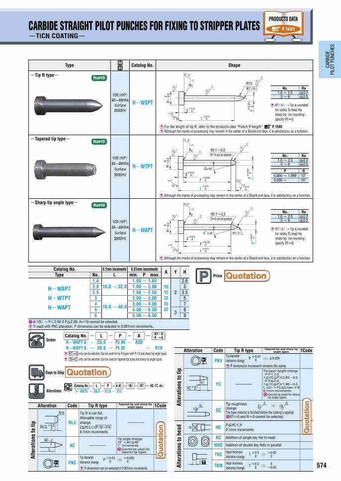

575 576
CARB
IDE
PILO
T PU
NCHE
S
CARBIDE STRAIGHT PILOT PUNCHES FOR FIXING TO STRIPPER PLATES-TIP R AND TAPER COMBINED TYPE, MINUS HEAD TOLERANCE, NORMAL・LAPPING・TiCN COATING-
CARBIDE PILOT PUNCHES FOR FIXING TO STRIPPER PLATES-TIP R AND TAPER COMBINED TYPE・MINUS HEAD TOLERANCE・NORMAL・LAPPING・TiCN COATING-
PRODUCTS DATA
P.1604
Type ~
Catalog No.Shape
Normal Lapping TiCN coating Surface hardness 3000HV
V30(HIP) 88~89HRA WSPTPF L-WSPTPF H-WSPTPF RT(※) Tip is rounded
for safety. To keep the sharp tip (no rounding), specify RT=0.
Catalog No. 0.1mm increments 0.001mm increments (With coating, 0.01mm increments)
B HType D L min. P max.
Normal WSPTPF
Lapping
L-WSPTPFTiCN coating
H-WSPTPF
1.6
10.0 ~ 32.0
0.800(1.00)~ 1.599
4
2.6
2.0 1.000 ~ 1.999 3.0
2.5 1.500 ~ 2.499 3.5
3 10.0 ~ 40.0 2.000 ~ 2.999 5 P>D-0.03 ℓ=0 If P>D-0.03, D-0.01
-0.03(press-in lead) is not included. (Y) Tip Y length=0.6+√(P-0.2)(39.8-P)/4 The coating process also forms an extremely thin coating layer on the shank. P(1.00) For TiCN coating is Pmin 1.00.
OrderCatalog No. - L - P -(RT=0)
WSPTPF 2.0- 28.0 - P1.900 - RT0H-WSPTPF 2.5- 30.0 - P2.20
RT=0 only can be selected.(However, lapping cannot be used.)
Days to Ship
AlterationsCatalog No. - L - P -(RT=0)-(BC・HC・TC, etc.)WSPTPF3 - 28.0 - P2.500 - RT0 - HC4.0
D Ra1.6 2.0 2.5 ≦0.2
3 ≦0.5
■Features ● These pilot punches for fixing to stripper plates were developed for use with press dies that are used with thin workpieces.
● The under-head dimension F is highly accurate and the tip is smoothly rounded.
Alteration Code Spec. 1Code
Alte
ratio
ns to
tip
BC
Tip length change 2≦BC≦Bmax. 0.1mm increments Full length L must be at least 8mm longer than
tip length BC.
RLCTip R is cut flat. 3≦RLC<Ymax. 0.1mm increments
PKC
Tip diameter tolerance change・Normal ・Lapping
P +0.0050 ⇨ +0.003
0
・TiCN coating P +0.010 ⇨ +0.005
0 P dimension can be selected in 0.001mm increments.
PKV
Tip diameter tolerance change・Normal ・Lapping
P +0.0050 ⇨ ±0.002
・TiCN coating P +0.010 ⇨ ±0.005
P dimension increment remains the same.
SC
Tip roughness changeThe base material is finished before the coating is applied. Can be used for coating types only.RT=0 and R=0 cannot be selected.
BBC
P
RLC 0+0.3
R10
┄
Alteration Code Spec. 1Code
Full l
ength
LKCFull length tolerance change L ±0.05 ⇨ +0.05
0
F dimension tolerance F +0.050 ⇨ ±0.05
Alte
ratio
ns to
hea
d HCHead diameter change D+0.1≦HC<H 0.1mm increments
TCHead thickness change 2≦TC<3 0.1mm increments The full length remains as specified.
KC Addition of single key flat to head
WKC Addition of double key flats in parallel
Othe
rs
NDC No press-in lead ℓ≧1 ⇨ ℓ=0
H HC
TTC
D-0.01-0.03ℓ
L ┄
Price
P Ymax.0.800~1.499 1.500~2.499 2.500~2.999
3 4 5
P Bmax.0.800~1.999 2.000~2.999
15 21
PRODUCTS DATA
P.1604
Type ~
Catalog No.Shape
Normal Lapping TiCN coating Surface hardness 3000HV
V30(HIP) 88~89HRA WSPTF L-WSPTF H-WSPTF RT(※) Tip is rounded
for safety. To keep the sharp tip (no rounding), specify RT=0.
Catalog No. 0.1mm increments 0.001mm increments (With coating, 0.01mm increments)
HType No. L min. P max.
Normal
WSPTFLapping
L-WSPTFTiCN coating
H-WSPTF
1.6
10.0 ~ 32.0
0.800(1.00)~ 1.600 2.6
2.0 1.000 ~ 2.000 3.0
2.5 1.500 ~ 2.500 3.5
3 10.0 ~ 40.0 2.000 ~ 3.000 5
(Y) Tip Y length=0.6+√(P-0.2)(39.8-P)/4 P(1.00) For TiCN coating is Pmin 1.00.
OrderCatalog No. - L - P -(RT=0)
WSPTF2.0 - 28.0 - P1.900 - RT0L-WSPTF2.5 - 30.0 - P2.205
RT=0 only can be selected.(However, lapping cannot be used.)
Days to Ship
AlterationsCatalog No. - L - P -(RT=0)-(RSC・HC・TC…etc.)
WSPTF 3 - 28.0 - P2.480 - RT0 -HC4.0-PKC
No. Ra1.6 2.0 2.5 ≦0.2
3 ≦0.5
■Features ● These pilot punches for fixing to stripper plates were developed for use with press dies that are used with thin workpieces.
● The under-head dimension F is highly accurate and the tip is smoothly rounded.
Alteration Code Spec. 1Code
Alte
ratio
ns to
tip
RLCTip R is cut flat. 3≦RLC<Ymax. 0.1mm increments
PKC
Tip diameter tolerance change・Normal・Lapping
P +0.0050 ⇨ +0.003
0
・TiCN coating P +0.010 ⇨ +0.005
0 P dimension can be selected in 0.001mm increments.
PKV
Tip diameter tolerance change・Normal・Lapping
P +0.0050 ⇨ ±0.002
・TiCN coating P +0.010 ⇨ ±0.005
P dimension increment remains the same.
SC
Tip roughness changeThe base material is finished before the coating is applied. Can be used for coating types only.RT=0 and R=0 cannot be selected.
P Ymax.0.800~1.499 1.500~2.499 2.500~3.000
3 4 5RLC 0
+0.3
R10
P┄
Alteration Code Spec. 1Code
Full l
ength
LKCFull length tolerance change L±0.05 ⇨ +0.05
0
F dimension tolerance F +0.050 ⇨ ±0.05
Alte
ratio
ns to
hea
d
HCHead diameter change 2.6≦P+0.1≦HC<H 0.1mm increments
TC
Head thickness change 2≦TC<3 0.1mm increments The full length remains as specified. Cannot be used with TiCN coating.
KC Addition of single key flat to head
WKC Addition of double key flats in parallel
H HC
TTC
L ┄
Price
BBC
P
RLC 0+0.3
R10
┄
H HC
TTC
L ┄
H HC
TTC
L ┄
0.2G GL
0.08⇨
0.2G GL
0.08⇨
0.08GL
0.08GL
-0.03-0.01
-0.
20
H
+0.0
05
B+0.3
+0.050F (Y)
0
P0
Ra
D
R2
RT(※)
L±0.05
03-0.02
Dm5
0.08GL
0.2G
P+0.
010
R101.5
10°
6.3G
1.6
G
G1.
6
Lapping
TiCN
coati
ng
Enlarged view
ℓ=10.08
GL
P+0.
010
R101.5
10°
L±0.05
-0.
2H
03-0.02
0
0+0.05
F
P0
R
+0.
005
RT(※)
(Y)
6.3G
1.6
G
0.2G
G1.
6
Lapping
Lapping range(13)
TiCN
coa
ting
Enlarged view
Although the marks of processing may remain in the center of a Shank end face, it is satisfactory on a function. Although the marks of processing may remain in the center of a Shank end face, it is satisfactory on a function.
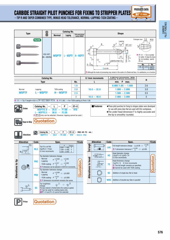
575 576
CARB
IDE
PILO
T PU
NCHE
S
CARBIDE STRAIGHT PILOT PUNCHES FOR FIXING TO STRIPPER PLATES-TIP R AND TAPER COMBINED TYPE, MINUS HEAD TOLERANCE, NORMAL・LAPPING・TiCN COATING-
CARBIDE PILOT PUNCHES FOR FIXING TO STRIPPER PLATES-TIP R AND TAPER COMBINED TYPE・MINUS HEAD TOLERANCE・NORMAL・LAPPING・TiCN COATING-
PRODUCTS DATA
P.1604
Type ~
Catalog No.Shape
Normal Lapping TiCN coating Surface hardness 3000HV
V30(HIP) 88~89HRA WSPTPF L-WSPTPF H-WSPTPF RT(※) Tip is rounded
for safety. To keep the sharp tip (no rounding), specify RT=0.
Catalog No. 0.1mm increments 0.001mm increments (With coating, 0.01mm increments)
B HType D L min. P max.
Normal WSPTPF
Lapping
L-WSPTPFTiCN coating
H-WSPTPF
1.6
10.0 ~ 32.0
0.800(1.00)~ 1.599
4
2.6
2.0 1.000 ~ 1.999 3.0
2.5 1.500 ~ 2.499 3.5
3 10.0 ~ 40.0 2.000 ~ 2.999 5 P>D-0.03 ℓ=0 If P>D-0.03, D-0.01
-0.03(press-in lead) is not included. (Y) Tip Y length=0.6+√(P-0.2)(39.8-P)/4 The coating process also forms an extremely thin coating layer on the shank. P(1.00) For TiCN coating is Pmin 1.00.
OrderCatalog No. - L - P -(RT=0)
WSPTPF 2.0- 28.0 - P1.900 - RT0H-WSPTPF 2.5- 30.0 - P2.20
RT=0 only can be selected.(However, lapping cannot be used.)
Days to Ship
AlterationsCatalog No. - L - P -(RT=0)-(BC・HC・TC, etc.)WSPTPF3 - 28.0 - P2.500 - RT0 - HC4.0
D Ra1.6 2.0 2.5 ≦0.2
3 ≦0.5
■Features ● These pilot punches for fixing to stripper plates were developed for use with press dies that are used with thin workpieces.
● The under-head dimension F is highly accurate and the tip is smoothly rounded.
Alteration Code Spec. 1Code
Alte
ratio
ns to
tip
BC
Tip length change 2≦BC≦Bmax. 0.1mm increments Full length L must be at least 8mm longer than
tip length BC.
RLCTip R is cut flat. 3≦RLC<Ymax. 0.1mm increments
PKC
Tip diameter tolerance change・Normal ・Lapping
P +0.0050 ⇨ +0.003
0
・TiCN coating P +0.010 ⇨ +0.005
0 P dimension can be selected in 0.001mm increments.
PKV
Tip diameter tolerance change・Normal ・Lapping
P +0.0050 ⇨ ±0.002
・TiCN coating P +0.010 ⇨ ±0.005
P dimension increment remains the same.
SC
Tip roughness changeThe base material is finished before the coating is applied. Can be used for coating types only.RT=0 and R=0 cannot be selected.
BBC
P
RLC 0+0.3
R10
┄
Alteration Code Spec. 1Code
Full l
ength
LKCFull length tolerance change L ±0.05 ⇨ +0.05
0
F dimension tolerance F +0.050 ⇨ ±0.05
Alte
ratio
ns to
hea
d HCHead diameter change D+0.1≦HC<H 0.1mm increments
TCHead thickness change 2≦TC<3 0.1mm increments The full length remains as specified.
KC Addition of single key flat to head
WKC Addition of double key flats in parallel
Othe
rs
NDC No press-in lead ℓ≧1 ⇨ ℓ=0
H HC
TTC
D-0.01-0.03ℓ
L ┄
Price
P Ymax.0.800~1.499 1.500~2.499 2.500~2.999
3 4 5
P Bmax.0.800~1.999 2.000~2.999
15 21
PRODUCTS DATA
P.1604
Type ~
Catalog No.Shape
Normal Lapping TiCN coating Surface hardness 3000HV
V30(HIP) 88~89HRA WSPTF L-WSPTF H-WSPTF RT(※) Tip is rounded
for safety. To keep the sharp tip (no rounding), specify RT=0.
Catalog No. 0.1mm increments 0.001mm increments (With coating, 0.01mm increments)
HType No. L min. P max.
Normal
WSPTFLapping
L-WSPTFTiCN coating
H-WSPTF
1.6
10.0 ~ 32.0
0.800(1.00)~ 1.600 2.6
2.0 1.000 ~ 2.000 3.0
2.5 1.500 ~ 2.500 3.5
3 10.0 ~ 40.0 2.000 ~ 3.000 5
(Y) Tip Y length=0.6+√(P-0.2)(39.8-P)/4 P(1.00) For TiCN coating is Pmin 1.00.
OrderCatalog No. - L - P -(RT=0)
WSPTF2.0 - 28.0 - P1.900 - RT0L-WSPTF2.5 - 30.0 - P2.205
RT=0 only can be selected.(However, lapping cannot be used.)
Days to Ship
AlterationsCatalog No. - L - P -(RT=0)-(RSC・HC・TC…etc.)
WSPTF 3 - 28.0 - P2.480 - RT0 - HC4.0-PKC
No. Ra1.6 2.0 2.5 ≦0.2
3 ≦0.5
■Features ● These pilot punches for fixing to stripper plates were developed for use with press dies that are used with thin workpieces.
● The under-head dimension F is highly accurate and the tip is smoothly rounded.
Alteration Code Spec. 1Code
Alte
ratio
ns to
tip
RLCTip R is cut flat. 3≦RLC<Ymax. 0.1mm increments
PKC
Tip diameter tolerance change・Normal・Lapping
P +0.0050 ⇨ +0.003
0
・TiCN coating P +0.010 ⇨ +0.005
0 P dimension can be selected in 0.001mm increments.
PKV
Tip diameter tolerance change・Normal・Lapping
P +0.0050 ⇨ ±0.002
・TiCN coating P +0.010 ⇨ ±0.005
P dimension increment remains the same.
SC
Tip roughness changeThe base material is finished before the coating is applied. Can be used for coating types only.RT=0 and R=0 cannot be selected.
P Ymax.0.800~1.499 1.500~2.499 2.500~3.000
3 4 5RLC 0
+0.3
R10
P┄
Alteration Code Spec. 1Code
Full l
ength
LKCFull length tolerance change L±0.05 ⇨ +0.05
0
F dimension tolerance F +0.050 ⇨ ±0.05
Alte
ratio
ns to
hea
d
HCHead diameter change 2.6≦P+0.1≦HC<H 0.1mm increments
TC
Head thickness change 2≦TC<3 0.1mm increments The full length remains as specified. Cannot be used with TiCN coating.
KC Addition of single key flat to head
WKC Addition of double key flats in parallel
H HC
TTC
L ┄
Price
BBC
P
RLC 0+0.3
R10
┄
H HC
TTC
L ┄
H HC
TTC
L ┄
0.2G GL
0.08⇨
0.2G GL
0.08⇨
0.08GL
0.08GL
-0.03-0.01
-0.
20
H
+0.0
05
B+0.3
+0.050F (Y)
0
P0
Ra
D
R2
RT(※)
L±0.05
03-0.02
Dm5
0.08GL
0.2G
P+0.
010
R101.5
10°
6.3G
1.6
G
G1.
6
Lapping
TiCN
coati
ng
Enlarged view
ℓ=10.08
GL
P+0.
010
R101.5
10°
L±0.05
-0.
2H
03-0.02
0
0+0.05
F
P0
R
+0.
005
RT(※)
(Y)
6.3G
1.6
G
0.2G
G1.
6
Lapping
Lapping range(13)
TiCN
coa
ting
Enlarged view
Although the marks of processing may remain in the center of a Shank end face, it is satisfactory on a function. Although the marks of processing may remain in the center of a Shank end face, it is satisfactory on a function.
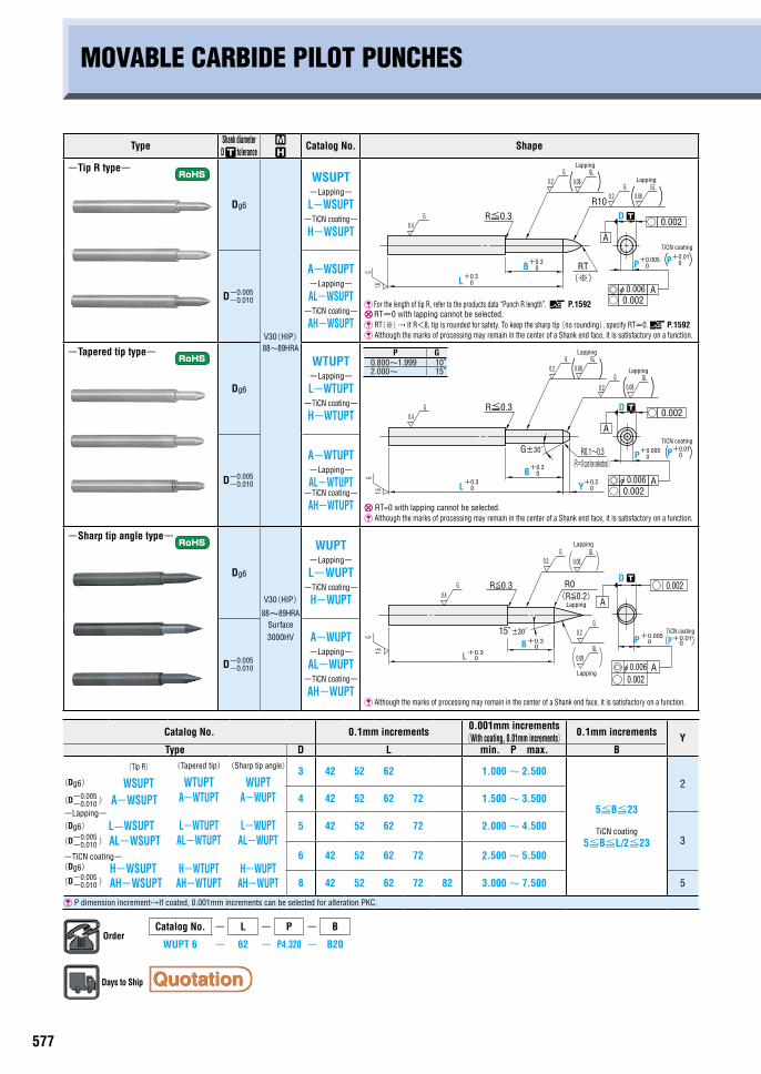
577 578
CARB
IDE
PILO
T PU
NCHE
S
AlterationsCatalog No. - L(LC)- P(PC)- B -(PKC, etc.)
WUPT 6 - LC60 - PC2.000 - B20 -PKC- GC30
Alteration Code Tip R type Tapered tip and sharp tip angle types 1Code
Alte
ratio
ns to
tip
PCPC≧Pmin./2 0.01mm increments If PC is 0.500 ~ 0.999, Bmax. is 8mm. ・-Coating type-P≧Pmin./2≧1.00 0.01mm increments
PKC
Tip diameter tolerance change・Normal ・Lapping
・TiCN coating
P dimension can be selected in 0.001mm increments.
PKV
Tip diameter tolerance change・Normal ・Lapping
・TiCN coating
P dimension increment remains the same.
RLCTip R is cut flat. Allowable range of change 2≦RLC<√P(10-P/4) 0.1mm increments
-
P +0.0050 ⇨ +0.003
0
P +0.010 ⇨ +0.005
0
P +0.0050 ⇨ ±0.002
P +0.010 ⇨ ±0.005
MOVABLE CARBIDE PILOT PUNCHESPRODUCTS DATA
P.1604
Type Shank diameter D tolerance
~
Catalog No. Shape
-Tip R type-
Dg6
V30(HIP) 88~89HRA
WSUPT -Lapping-
L-WSUPT -TiCN coating-
H-WSUPT
For the length of tip R, refer to the products data “Punch R length”. P.1592 RT=0 with lapping cannot be selected. RT(※) If R<8, tip is rounded for safety. To keep the sharp tip (no rounding), specify RT=0. P.1592 Although the marks of processing may remain in the center of a Shank end face, it is satisfactory on a function.
D-0.005-0.010
A-WSUPT -Lapping-
AL-WSUPT -TiCN coating-
AH-WSUPT
-Tapered tip type-
Dg6
WTUPT -Lapping-
L-WTUPT -TiCN coating-
H-WTUPT
RT=0 with lapping cannot be selected. Although the marks of processing may remain in the center of a Shank end face, it is satisfactory on a function.
D-0.005-0.010
A-WTUPT -Lapping-
AL-WTUPT -TiCN coating-
AH-WTUPT
-Sharp tip angle type-
Dg6
V30(HIP)
88~89HRA Surface 3000HV
WUPT -Lapping-
L-WUPT -TiCN coating-
H-WUPT
Although the marks of processing may remain in the center of a Shank end face, it is satisfactory on a function.
D-0.005-0.010
A-WUPT -Lapping-
AL-WUPT -TiCN coating-
AH-WUPT
Catalog No. 0.1mm increments 0.001mm increments (With coating, 0.01mm increments)
0.1mm increments YType D L min. P max. B
(Dg6)
(Tip R) WSUPT
(Tapered tip)
WTUPT(Sharp tip angle)
WUPT3 42 52 62 1.000 ~ 2.500
5≦B≦23
TiCN coating 5≦B≦L/2≦23
2(D-0.005
-0.010 ) A-WSUPT A-WTUPT A-WUPT 4 42 52 62 72 1.500 ~ 3.500-Lapping-(Dg6) L-WSUPT L-WTUPT L-WUPT 5 42 52 62 72 2.000 ~ 4.500
3(D-0.005-0.010 ) AL-WSUPT
-TiCN coating-
AL-WTUPT AL-WUPT6 42 52 62 72 2.500 ~ 5.500
(Dg6)
(D-0.005-0.010 )
H-WSUPTAH-WSUPT
H-WTUPTAH-WTUPT
H-WUPTAH-WUPT 8 42 52 62 72 82 3.000 ~ 7.500 5
P dimension incrementIf coated, 0.001mm increments can be selected for alteration PKC.
OrderCatalog No. - L - P - B
WUPT 6 - 62 - P4.320 - B20
Days to Ship
L+0.30
B+0.30
R≦0.3
R10
A
A◎○ 0.002
○ 0.002D ┄
( )( )
P+0.010P+0.005
0 (RT(※)
0.08GL
0.2G
0.2G
0.4G
1.6G
0.08GL
)
Lapping
Lapping
TiCN coating
φ0.006
L+0.30
B+0.30
R≦0.3
A
A◎○ 0.002
○ 0.002D ┄
( )( )
P+0.010P+0.005
0 (R0.1~0.3G±30́
Y+0.30
0.2G
0.2G
0.4G
1.6G
0.08GL
0.08GL
)
Lapping
TiCN coating
Lapping
φ0.006
(R=0 can be selected.)
BL
R≦0.3 R0
+0.30
+0.30
1.6G
0.4G
15°±30́P 0
0.002
A
0.002A
+0.005
(R≦0.2)
0.2G
0.2G
0.08GL
0.08GL
P+0.010
D ┄
Lapping
TiCN coating
Lapping
Lapping
φ0.006
P G0.800~1.999 10°2.000~ 15°
PC PP ┄
RLC 0+0.3
R10
Alteration Code Tip R type Tapered tip and sharp tip angle types 1Code
Alte
ratio
ns to
tip
BKC -Tip length tolerance change
B +0.30 ⇨ +0.05
0
SC
Tip roughness change ⇨
The base material is finished before the coating is applied. Can be used for coating types only. R=0 R≦0.2
GC -
Tip angle change 15°<GC≦45° 1° increments Cannot be used for tapered tip types.
YC -
Tip taper length change ・If P<2.0, 1≦YC≦P×2.83-0.3 ・If P≧2.0, 1≦YC≦P×1.86-0.3≦12 L(LC)+YC≦Lmax.+8 0.1mm increments Cannot be used for sharp
tip angle types.
Alterati
ons to f
ull leng
th
LC Full length change B+9≦LC<L 0.1mm increments
B
L
GC
0.08GL
LCL
YC+0.30
Y
┄
0.2G
0.08GL
Price
PC PP ┄
RLC 0+0.3
R10
Example
DP
SP
PP
BP
■Features① No height adjustment is required after
regrinding.② Because it is possible to remove the
pilot punch without disassembling the die, the number of steps required for regrinding can be reduced.
③ Even if a misfeed occurs, because the pilot punches themselves are moveable, it is possible to prevent the punch from biting into the workpiece or being broken.

577 578
CARB
IDE
PILO
T PU
NCHE
S
AlterationsCatalog No. - L(LC)- P(PC)- B -(PKC, etc.)
WUPT 6 - LC60 - PC2.000 - B20 -PKC- GC30
Alteration Code Tip R type Tapered tip and sharp tip angle types 1Code
Alte
ratio
ns to
tip
PCPC≧Pmin./2 0.01mm increments If PC is 0.500 ~ 0.999, Bmax. is 8mm. ・-Coating type-P≧Pmin./2≧1.00 0.01mm increments
PKC
Tip diameter tolerance change・Normal ・Lapping
・TiCN coating
P dimension can be selected in 0.001mm increments.
PKV
Tip diameter tolerance change・Normal ・Lapping
・TiCN coating
P dimension increment remains the same.
RLCTip R is cut flat. Allowable range of change 2≦RLC<√P(10-P/4) 0.1mm increments
-
P +0.0050 ⇨ +0.003
0
P +0.010 ⇨ +0.005
0
P +0.0050 ⇨ ±0.002
P +0.010 ⇨ ±0.005
MOVABLE CARBIDE PILOT PUNCHESPRODUCTS DATA
P.1604
Type Shank diameter D tolerance
~
Catalog No. Shape
-Tip R type-
Dg6
V30(HIP) 88~89HRA
WSUPT -Lapping-
L-WSUPT -TiCN coating-
H-WSUPT
For the length of tip R, refer to the products data “Punch R length”. P.1592 RT=0 with lapping cannot be selected. RT(※) If R<8, tip is rounded for safety. To keep the sharp tip (no rounding), specify RT=0. P.1592 Although the marks of processing may remain in the center of a Shank end face, it is satisfactory on a function.
D-0.005-0.010
A-WSUPT -Lapping-
AL-WSUPT -TiCN coating-
AH-WSUPT
-Tapered tip type-
Dg6
WTUPT -Lapping-
L-WTUPT -TiCN coating-
H-WTUPT
RT=0 with lapping cannot be selected. Although the marks of processing may remain in the center of a Shank end face, it is satisfactory on a function.
D-0.005-0.010
A-WTUPT -Lapping-
AL-WTUPT -TiCN coating-
AH-WTUPT
-Sharp tip angle type-
Dg6
V30(HIP)
88~89HRA Surface 3000HV
WUPT -Lapping-
L-WUPT -TiCN coating-
H-WUPT
Although the marks of processing may remain in the center of a Shank end face, it is satisfactory on a function.
D-0.005-0.010
A-WUPT -Lapping-
AL-WUPT -TiCN coating-
AH-WUPT
Catalog No. 0.1mm increments 0.001mm increments (With coating, 0.01mm increments)
0.1mm increments YType D L min. P max. B
(Dg6)
(Tip R) WSUPT
(Tapered tip)
WTUPT(Sharp tip angle)
WUPT3 42 52 62 1.000 ~ 2.500
5≦B≦23
TiCN coating 5≦B≦L/2≦23
2(D-0.005
-0.010 ) A-WSUPT A-WTUPT A-WUPT 4 42 52 62 72 1.500 ~ 3.500-Lapping-(Dg6) L-WSUPT L-WTUPT L-WUPT 5 42 52 62 72 2.000 ~ 4.500
3(D-0.005-0.010 ) AL-WSUPT
-TiCN coating-
AL-WTUPT AL-WUPT6 42 52 62 72 2.500 ~ 5.500
(Dg6)
(D-0.005-0.010 )
H-WSUPTAH-WSUPT
H-WTUPTAH-WTUPT
H-WUPTAH-WUPT 8 42 52 62 72 82 3.000 ~ 7.500 5
P dimension incrementIf coated, 0.001mm increments can be selected for alteration PKC.
OrderCatalog No. - L - P - B
WUPT 6 - 62 - P4.320 - B20
Days to Ship
L+0.30
B+0.30
R≦0.3
R10
A
A◎○ 0.002
○ 0.002D ┄
( )( )
P+0.010P+0.005
0 (RT(※)
0.08GL
0.2G
0.2G
0.4G
1.6G
0.08GL
)
Lapping
Lapping
TiCN coating
φ0.006
L+0.30
B+0.30
R≦0.3
A
A◎○ 0.002
○ 0.002D ┄
( )( )
P+0.010P+0.005
0 (R0.1~0.3G±30́
Y+0.30
0.2G
0.2G
0.4G
1.6G
0.08GL
0.08GL
)
Lapping
TiCN coating
Lapping
φ0.006
(R=0 can be selected.)
BL
R≦0.3 R0
+0.30
+0.30
1.6G
0.4G
15°±30́P 0
0.002
A
0.002A
+0.005
(R≦0.2)
0.2G
0.2G
0.08GL
0.08GL
P+0.010
D ┄
Lapping
TiCN coating
Lapping
Lapping
φ0.006
P G0.800~1.999 10°2.000~ 15°
PC PP ┄
RLC 0+0.3
R10
Alteration Code Tip R type Tapered tip and sharp tip angle types 1Code
Alte
ratio
ns to
tip
BKC -Tip length tolerance change
B +0.30 ⇨ +0.05
0
SC
Tip roughness change ⇨
The base material is finished before the coating is applied. Can be used for coating types only. R=0 R≦0.2
GC -
Tip angle change 15°<GC≦45° 1° increments Cannot be used for tapered tip types.
YC -
Tip taper length change ・If P<2.0, 1≦YC≦P×2.83-0.3 ・If P≧2.0, 1≦YC≦P×1.86-0.3≦12 L(LC)+YC≦Lmax.+8 0.1mm increments Cannot be used for sharp
tip angle types.
Alterati
ons to f
ull leng
thLC Full length change
B+9≦LC<L 0.1mm increments
B
L
GC
0.08GL
LCL
YC+0.30
Y
┄
0.2G
0.08GL
Price
PC PP ┄
RLC 0+0.3
R10
Example
DP
SP
PP
BP
■Features① No height adjustment is required after
regrinding.② Because it is possible to remove the
pilot punch without disassembling the die, the number of steps required for regrinding can be reduced.
③ Even if a misfeed occurs, because the pilot punches themselves are moveable, it is possible to prevent the punch from biting into the workpiece or being broken.


