

“Linear and Rotational Motion Analysis in Traffic Crash Reconstruction” http://www.iptm.org/Webstore/p-122-linear-and-rotational-motion-analysis-in-traffic-crash-reconstruction.aspx
5-18
Case Study 1
Scenario: A 1991 Buick Century sedan (Buick) was westbound and stopped at a stop
sign at an intersection with a four lane divided highway. The female driver of the Buick
intended to make a left turn on US-1. She pulled across the northbound lanes and
stopped partially in the median to wait for traffic to clear in the southbound lanes so that
she could complete her turn. Concurrently, a 1997 Kawasaki Vulcan 750 motorcycle
(Kawasaki), operated by a male, was traveling in the left northbound lane of the
highway. An impact occurred between the front of the Kawasaki and the left rear of the
Buick. The Buick rotated counter clockwise heading east at final rest. The police report
diagram (Figure 5-8) showed the final rest position to the south of its position at impact,
which clearly violates the laws of conservation of linear momentum; however, the angle
of final rest was confirmed by all parties to be accurate. The speed limit for the
northbound traffic on US-1 was 60 miles per hour.
Figure 5-8

“Linear and Rotational Motion Analysis in Traffic Crash Reconstruction” http://www.iptm.org/Webstore/p-122-linear-and-rotational-motion-analysis-in-traffic-crash-reconstruction.aspx
5-19
The damage to the Buick shows a distinct tire print on the rear edge of the left rear door,
forward of the left rear wheel well. Additional damage is noted to the left ‘C’ pillar area.
The left rear wheel is missing, with damage to the front portion of the wheel well. The
unibody is bowed and concaved at the point of impact, Figures 5-9 and 5-10.
Figure 5-9

“Linear and Rotational Motion Analysis in Traffic Crash Reconstruction” http://www.iptm.org/Webstore/p-122-linear-and-rotational-motion-analysis-in-traffic-crash-reconstruction.aspx
5-20
Figure 5-10
The photographs of the Kawasaki illustrate an impact from the front (Figures 5-11 and
5-12). The front fork tubes are bent rearward approximately 20° on the left and
approximately 15° on the right. The handlebars were broken off the top of the fork
tubes. The gas tank was dented on the top rear and demonstrated adjacent side
damage that appeared to have been caused by compression from the sides due to the
thighs of the driver. The front alloy wheel, which appears to have seven spokes, shows
some deformation of the rim, consistent with an impact adjacent to one of the spokes.
The tire and rim are pushed into the radiator/engine area of the motorcycle. The front
tire appears to still be inflated.

“Linear and Rotational Motion Analysis in Traffic Crash Reconstruction” http://www.iptm.org/Webstore/p-122-linear-and-rotational-motion-analysis-in-traffic-crash-reconstruction.aspx
5-21
Figure 5-11
Figure 5-12
The roadway was inspected and documented. A scale diagram of the scene was
drawn, as shown in Figure 5-13. The approximate point of impact was based on the
geometry of the intersection and statements of the Buick’s driver. The post impact
position of the Buick was based on testimony of the two drivers and a witness that
arrived on the scene before the Buick was moved. The final rest of the Kawasaki based
on a fluid mark on the roadway. The final rest of the Kawasaki driver was based on his
testimony.

“Linear and Rotational Motion Analysis in Traffic Crash Reconstruction” http://www.iptm.org/Webstore/p-122-linear-and-rotational-motion-analysis-in-traffic-crash-reconstruction.aspx
5-22
Figure 5-13
The driver of the Kawasaki indicated that he had locked up his brakes at least 15 feet
prior to impact.
The driver of the Buick indicated that she had a trunk full of items, which she listed in
detail. The estimated weight of the items in the trunk was 105 pounds. The driver was
estimated to weigh 139 pounds, the weight of a 50 percentile adult female (Woodson,
1992).
“Linear and Rotational Motion Analysis in Traffic Crash Reconstruction” http://www.iptm.org/Webstore/p-122-linear-and-rotational-motion-analysis-in-traffic-crash-reconstruction.aspx
5-23
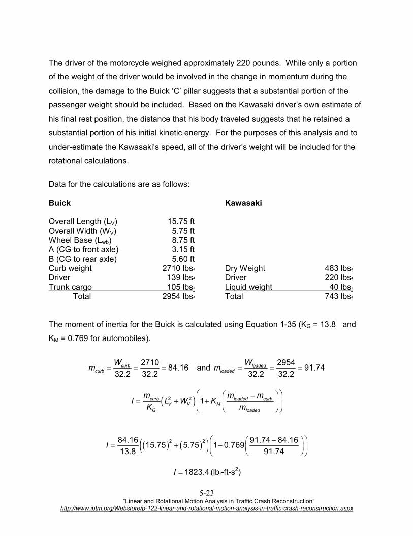
The driver of the motorcycle weighed approximately 220 pounds. While only a portion
of the weight of the driver would be involved in the change in momentum during the
collision, the damage to the Buick ‘C’ pillar suggests that a substantial portion of the
passenger weight should be included. Based on the Kawasaki driver’s own estimate of
his final rest position, the distance that his body traveled suggests that he retained a
substantial portion of his initial kinetic energy. For the purposes of this analysis and to
under-estimate the Kawasaki’s speed, all of the driver’s weight will be included for the
rotational calculations.
Data for the calculations are as follows: Buick Kawasaki Overall Length (LV) 15.75 ft Overall Width (WV) 5.75 ft Wheel Base (Lwb) 8.75 ft A (CG to front axle) 3.15 ft B (CG to rear axle) 5.60 ft Curb weight 2710 lbsf Dry Weight 483 lbsf Driver 139 lbsf Driver 220 lbsf Trunk cargo 105 lbsf Liquid weight 40 lbsf Total 2954 lbsf Total 743 lbsf The moment of inertia for the Buick is calculated using Equation 1-35 (KG = 13.8 and
KM = 0.769 for automobiles).
271084.16
32.2 32.2curb
curb
Wm = = = and
295491.74
32.2 32.2loaded
loaded
Wm = = =
( )2 2 1curb loaded curbV V M
G loaded
m m mI L W K
K m
−= + +
( ) ( )( )2 284.16 91.74 84.1615.75 5.75 1 0.769
13.8 91.74I
− = + +
1823.4I = (lbf-ft-s
2)

“Linear and Rotational Motion Analysis in Traffic Crash Reconstruction” http://www.iptm.org/Webstore/p-122-linear-and-rotational-motion-analysis-in-traffic-crash-reconstruction.aspx
5-24
The Buick was stopped at impact and rotated at least 160°. Using the composite best
fit line on Figure 4-1, 0.72ξ ≈ . The median on which the Buick was stopped was
asphalt with loose gravel and therefore, the roadway friction was estimated at 0.6. The
rotational friction factor (fr) is calculated as follows:
( )0.72 (0.6) 0.43rf fξ= = ≈
The impact was approximately 14 inches forward of the rear axle, therefore the axial
distance from the center of gravity to the impact is:
14 /12 5.60 1.17 4.43d B= − = − = ft
The vehicle is at an approximate 20 degree angle with the roadway, therefore, the
perpendicular distance to the line of force is calculated as follows (refer to Figure 5-13):
1 1/ 2 5.75 / 2tan tan 33
4.43
ov
I
W
dθ − − = = =
( )2 2
22 5.754.43 5.28
2 2
v
I
Wr d
= + = + =
ft
cos( 20) 5.28cos(33 20) 5.14I I Id r θ= − = − = ft
Figure 5-14
“Linear and Rotational Motion Analysis in Traffic Crash Reconstruction” http://www.iptm.org/Webstore/p-122-linear-and-rotational-motion-analysis-in-traffic-crash-reconstruction.aspx
5-25
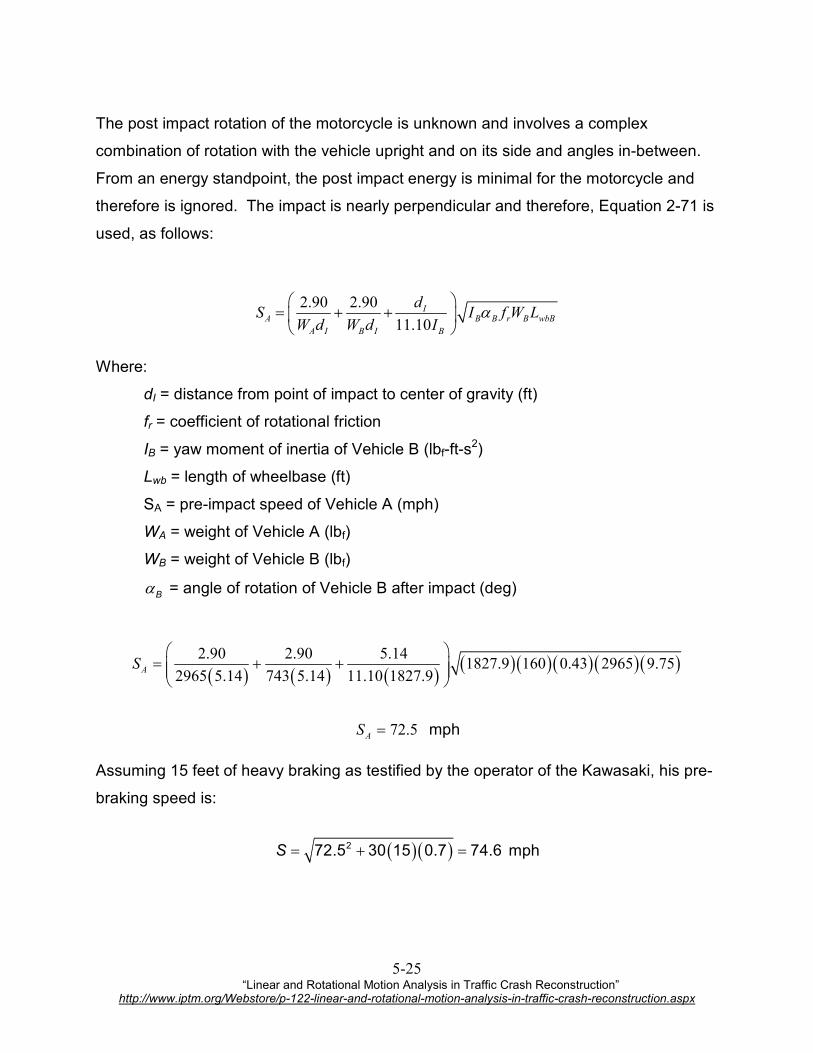
The post impact rotation of the motorcycle is unknown and involves a complex
combination of rotation with the vehicle upright and on its side and angles in-between.
From an energy standpoint, the post impact energy is minimal for the motorcycle and
therefore is ignored. The impact is nearly perpendicular and therefore, Equation 2-71 is
used, as follows:
2.90 2.90
11.10
IA B B r B wbB
A I B I B
dS I f W L
W d W d Iα
= + +
Where:
dI = distance from point of impact to center of gravity (ft)
fr = coefficient of rotational friction
IB = yaw moment of inertia of Vehicle B (lbf-ft-s2)
Lwb = length of wheelbase (ft)
SA = pre-impact speed of Vehicle A (mph)
WA = weight of Vehicle A (lbf)
WB = weight of Vehicle B (lbf)
Bα = angle of rotation of Vehicle B after impact (deg)
( ) ( ) ( )( )( )( ) ( )( )2.90 2.90 5.141827.9 160 0.43 2965 9.75
2965 5.14 743 5.14 11.10 1827.9
= + +
AS
72.5=AS mph
Assuming 15 feet of heavy braking as testified by the operator of the Kawasaki, his pre-
braking speed is:
( ) ( )272.5 30 15 0.7 74.6S = + = mph


