
ENCORE™ MULTI-POINT
LOCKING SYSTEM
18
Providing trouble free operation withfully concealed locking and sequentialengagement the Encore Multi-PointLocking System is the most completelocking system for casement andawning windows. The Encore Lockbrings a number of new features uniqueto the window industry – including anoption for securing round-top windowsand a built-in construction handle whichallows windows to be operable prior topainting or staining. In addition, theEncore Lock features the followingadvancements:
Easy to install – fewer screws, fewerparts, prelocated guides and simplerside stop machining are sure to benefitthe manufacturer.
Stronger – Tested to beyond DP 85 ona 36" x 72" window with only threelock points. The Encore is also rated to400 lbs. per lock point, dependingupon application.
Handle Action – Built-in detents,reduced handle to jamb contact and atighter escutcheon means the Encorelock is more reliable and resistant toinsect and light infiltration.
ADDITIONAL FEATURES &
BENEFITS INCLUDE:
• Interchangeable handle andescutcheon allows homeowner toeasily change the color and style ofthe hardware
• Escutcheon snaps into lock driverather than into wood, producing amore secure connection.
• Locking points can be both above andbelow the handle for added flexibility.
• Detent in locked and unlockedpositions eliminates tie bar drop inshipping and helps to pass impacttesting.
• Window preparation for Encore doesnot require CNC machining of thestop.
• Pre-located guides on tie bars makesthem easier to install.
• Single kerf locating allows use of asingle screw at each guide whichreduces machining and installationtime and cost.
• Handed tie bar with 1 to 4 lockingpoints.
• Available with surface mount (flange)or recessed (biscuit-style) keepers
• Stainless steel components forcoastal applications are also available.
• Convert from Truth’s Mirage™ Lockto the Encore system withoutrecertifying your window.
PRODUCT APPLICATION
ASSISTANCE
If you are designing a new windowprofile, or are having difficultyselecting hardware for your window,please contact Truth. Our highlytrained Product Specialists can assistyou with the selection of the appropriatehardware to meet your performancerequirements, as well as providingpersonalized application drawings.
CORROSION RESISTANCE
Truth’s E-Gard® Hardware has a multi-stage coating process that producesa superior physical and aesthetic finish.Plus, it is resistant to a wider range ofcorrosive materials, includingindustrial cleaning materials andenvironmental pollutants. Thisproprietary process has been tested tobe approximately three times betterthan common zinc plated finishes.Stainless steel components for coastalapplications are also available.
WARRANTY:
Protected under the terms of the Truth Warranty for Window & DoorManufacturers & AuthorizedDistributors. Refer to Truth’s Terms & Conditions for further details.
MATERIAL:
Molded in color plastic handle andescutcheon, Stamped steel andengineered plastic lock drive, Steeltiebar with engineered plastic guides,keepers of high strength steel orstainless steel.
FINISH:
The removable handle and escutcheonare constructed of durable, fade andscratch resistant plastic. These aresupplied with color molded in forconsistency with our painted products.Please refer to Truth’s Color Chart forexamples of Truth’s most popularfinish options.
Truth also offers a wide range ofdecorative “plated” finishes – contactTruth for additional information onavailability of these finishes on specificproduct lines.
CASEMENTAWNING
ORDERING INFORMATION
If application assistance is needed,please contact Truth Hardware’sProduct Specialists.
1. Order Non-handed Encore™ lockdrive by part number.#12642.92 Encore lock drive assembly
2. Order Non-handed Encore TangoSash Lock handle and escutcheon pack#12662.XX Encore Tango handle andescutcheon (painted)
3. Specify finish number.
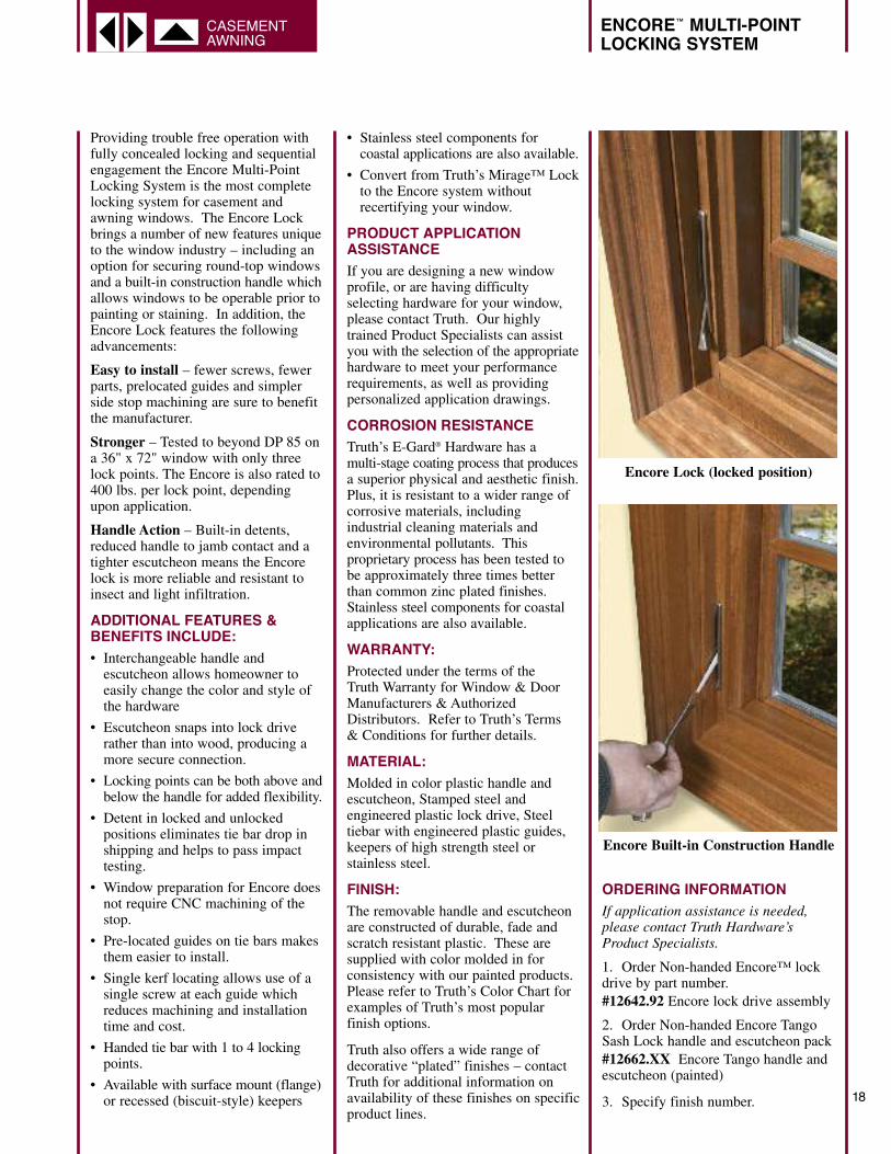
Encore Lock (locked position)
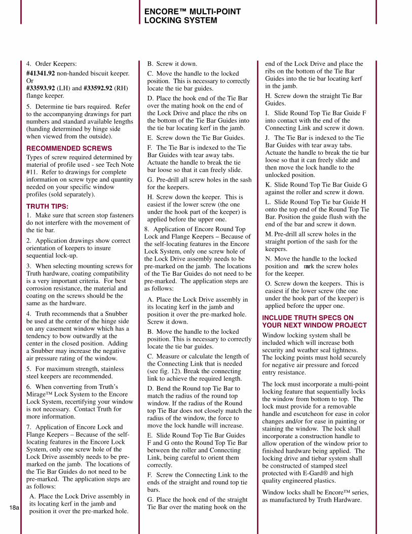
Encore Built-in Construction Handle
ENCORE™ MULTI-POINT
LOCKING SYSTEM
18a
4. Order Keepers:
#41341.92 non-handed biscuit keeper.Or#33593.92 (LH) and #33592.92 (RH)flange keeper.
5. Determine tie bars required. Referto the accompanying drawings for partnumbers and standard available lengths(handing determined by hinge sidewhen viewed from the outside).
RECOMMENDED SCREWS
Types of screw required determined bymaterial of profile used - see Tech Note#11. Refer to drawings for completeinformation on screw type and quantityneeded on your specific windowprofiles (sold separately).
TRUTH TIPS:
1. Make sure that screen stop fastenersdo not interfere with the movement ofthe tie bar.
2. Application drawings show correctorientation of keepers to insuresequential lock-up.
3. When selecting mounting screws forTruth hardware, coating compatibilityis a very important criteria. For bestcorrosion resistance, the material andcoating on the screws should be thesame as the hardware.
4. Truth recommends that a Snubberbe used at the center of the hinge sideon any casement window which has atendency to bow outwardly at thecenter in the closed position. Adding a Snubber may increase the negativeair pressure rating of the window.
5. For maximum strength, stainlesssteel keepers are recommended.
6. When converting from Truth’sMirage™ Lock System to the EncoreLock System, recertifying your windowis not necessary. Contact Truth formore information.
7. Application of Encore Lock andFlange Keepers – Because of the self-locating features in the Encore LockSystem, only one screw hole of theLock Drive assembly needs to be pre-marked on the jamb. The locations ofthe Tie Bar Guides do not need to bepre-marked. The application steps areas follows:
A. Place the Lock Drive assembly inits locating kerf in the jamb andposition it over the pre-marked hole.
B. Screw it down.
C. Move the handle to the lockedposition. This is necessary to correctlylocate the tie bar guides.
D. Place the hook end of the Tie Barover the mating hook on the end ofthe Lock Drive and place the ribs onthe bottom of the Tie Bar Guides intothe tie bar locating kerf in the jamb.
E. Screw down the Tie Bar Guides.
F. The Tie Bar is indexed to the TieBar Guides with tear away tabs.Actuate the handle to break the tie bar loose so that it can freely slide.
G. Pre-drill all screw holes in the sashfor the keepers.
H. Screw down the keeper. This iseasiest if the lower screw (the oneunder the hook part of the keeper) isapplied before the upper one.
8. Application of Encore Round TopLock and Flange Keepers – Because ofthe self-locating features in the EncoreLock System, only one screw hole ofthe Lock Drive assembly needs to bepre-marked on the jamb. The locationsof the Tie Bar Guides do not need to bepre-marked. The application steps areas follows:
A. Place the Lock Drive assembly inits locating kerf in the jamb andposition it over the pre-marked hole.Screw it down.
B. Move the handle to the lockedposition. This is necessary to correctlylocate the tie bar guides.
C. Measure or calculate the length ofthe Connecting Link that is needed(see fig. 12). Break the connectinglink to achieve the required length.
D. Bend the Round top Tie Bar tomatch the radius of the round topwindow. If the radius of the Roundtop Tie Bar does not closely match theradius of the window, the force tomove the lock handle will increase.
E. Slide Round Top Tie Bar Guides F and G onto the Round Top Tie Barbetween the roller and ConnectingLink, being careful to orient themcorrectly.
F. Screw the Connecting Link to theends of the straight and round top tiebars.
G. Place the hook end of the straightTie Bar over the mating hook on the
end of the Lock Drive and place theribs on the bottom of the Tie BarGuides into the tie bar locating kerf in the jamb.
H. Screw down the straight Tie BarGuides.
I. Slide Round Top Tie Bar Guide Finto contact with the end of theConnecting Link and screw it down.
J. The Tie Bar is indexed to the TieBar Guides with tear away tabs.Actuate the handle to break the tie barloose so that it can freely slide andthen move the lock handle to theunlocked position.
K. Slide Round Top Tie Bar Guide Gagainst the roller and screw it down.
L. Slide Round Top Tie bar Guide Honto the top end of the Round Top TieBar. Position the guide flush with theend of the bar and screw it down.
M. Pre-drill all screw holes in thestraight portion of the sash for thekeepers.
N. Move the handle to the lockedposition and mark the screw holes for the keeper.
O. Screw down the keepers. This iseasiest if the lower screw (the oneunder the hook part of the keeper) isapplied before the upper one.
INCLUDE TRUTH SPECS ON
YOUR NEXT WINDOW PROJECT
Window locking system shall beincluded which will increase bothsecurity and weather seal tightness.The locking points must hold securelyfor negative air pressure and forcedentry resistance.
The lock must incorporate a multi-pointlocking feature that sequentially locksthe window from bottom to top. Thelock must provide for a removablehandle and escutcheon for ease in colorchanges and/or for ease in painting orstaining the window. The lock shallincorporate a construction handle toallow operation of the window prior tofinished hardware being applied. Thelocking drive and tiebar system shallbe constructed of stamped steelprotected with E-Gard® and highquality engineered plastics.
Window locks shall be Encore™ series,as manufactured by Truth Hardware.

18b
ENCORE™ MULTI-POINT
LOCKING SYSTEM
FIG. 1 CASEMENT APPLICATION WITH FLANGE KEEPER
NOTES:
1 ACCURACY OF INDICATED DIMENSIONS IS CRITICAL TO THE FUNCTION OF THE MULTI-POINT LOCK
2. "A", "B" AND "C" DIMENSIONS ARE CONFIGURED TO GIVE SEQUENTIAL LOCKING, STARTING WITH THE BOTTOM LOCKING POINT. REFER TO FIG. 4
3. TIE BAR MOVES APPROX. 1.50" (38.1 mm)
4. CONTACT TECHNICAL SERVICES FOR TIE BAR INFORMATION
LEFT HAND SHOWN
B
A
12662.XXSEE FIG. 533593.92 12642.92
PART NO.ENCORE TANGO HANDLE AND ESCUTCHEONENCORE TIE BAR ASSEMBLYSTEEL KEEPER, LH FLANGE (33592.92 RH)(QTY:1 PER LOCK POINT)ENCORE LOCK DRIVE ASSSEMBLY
[109.5 mm]4.310
B
A
TIE BAR ASSEMBLY
[93.7 mm]3.690
1
A1
B 1
[26.0 mm]1.025 1
[57.1 mm][44.4 mm]
2.2501.750
SECTION A-ALOCK DRIVE MOUNTING
[19.9 mm](.785)
[5.4 mm].213
ROUND SCREW HOLE
[4.2 mm].165
SLOTTED SCREW HOLE
SECTION B-BTIE BAR & KEEPER MOUNTING
1
1
[28.6 mm]1.125
ESCUTCHEON
HANDLE
DESCRIPTIONHARDWARE SHOWN
TIE BAR LENGTH
LOCKDRIVEASSEMBLY
1C
OF LOCK(8.275)
FLANGE KEEPER
(5.000)
ENCORE™ MULTI-POINT
LOCKING SYSTEM
18c
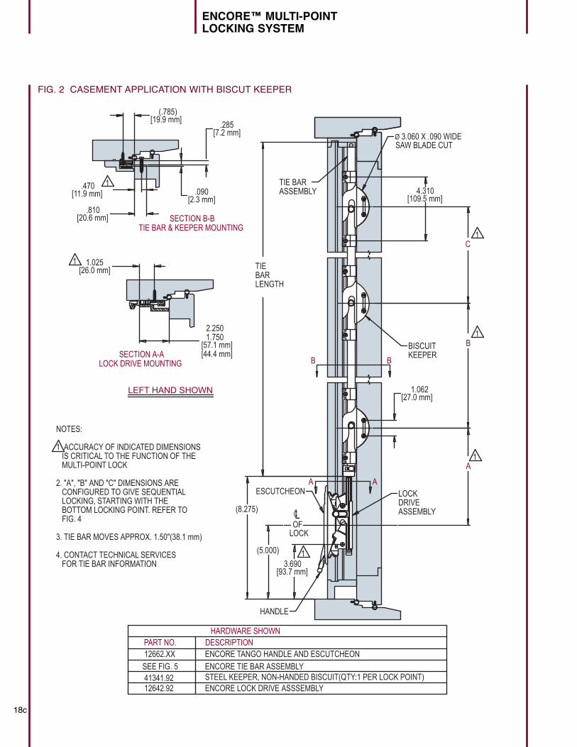
FIG. 2 CASEMENT APPLICATION WITH BISCUT KEEPER
[7.2 mm].285
[2.3 mm].090
F
LEFT HAND SHOWN
(8.275)
OFLOCK
[93.7 mm]3.690
[109.5 mm]4.310
B
A
TIE BARASSEMBLY
HANDLE
ESCUTCHEON
NOTES:
1 ACCURACY OF INDICATED DIMENSIONS IS CRITICAL TO THE FUNCTION OF THE MULTI-POINT LOCK
2. "A", "B" AND "C" DIMENSIONS ARE CONFIGURED TO GIVE SEQUENTIAL LOCKING, STARTING WITH THE BOTTOM LOCKING POINT. REFER TO FIG. 4
3. TIE BAR MOVES APPROX. 1.50"(38.1 mm)
4. CONTACT TECHNICAL SERVICES FOR TIE BAR INFORMATION
1
1
1
[11.9 mm].470 1
SECTION B-BTIE BAR & KEEPER MOUNTING
[26.0 mm]1.0251
[57.1 mm][44.4 mm]
2.2501.750
SECTION A-ALOCK DRIVE MOUNTING
[19.9 mm](.785)
BISCUIT KEEPER
1C
(5.000)
12662.XX
SEE FIG. 541341.92 12642.92
PART NO.ENCORE TANGO HANDLE AND ESCUTCHEON
ENCORE TIE BAR ASSEMBLYSTEEL KEEPER, NON-HANDED BISCUIT(QTY:1 PER LOCK POINT)ENCORE LOCK DRIVE ASSSEMBLY
DESCRIPTIONHARDWARE SHOWN
[20.6 mm].810
B B
A A
[27.0 mm]1.062
LOCKDRIVEASSEMBLY
TIEBARLENGTH
SAW BLADE CUTØ 3.060 X .090 WIDE
LC
18d
ENCORE™ MULTI-POINT
LOCKING SYSTEM
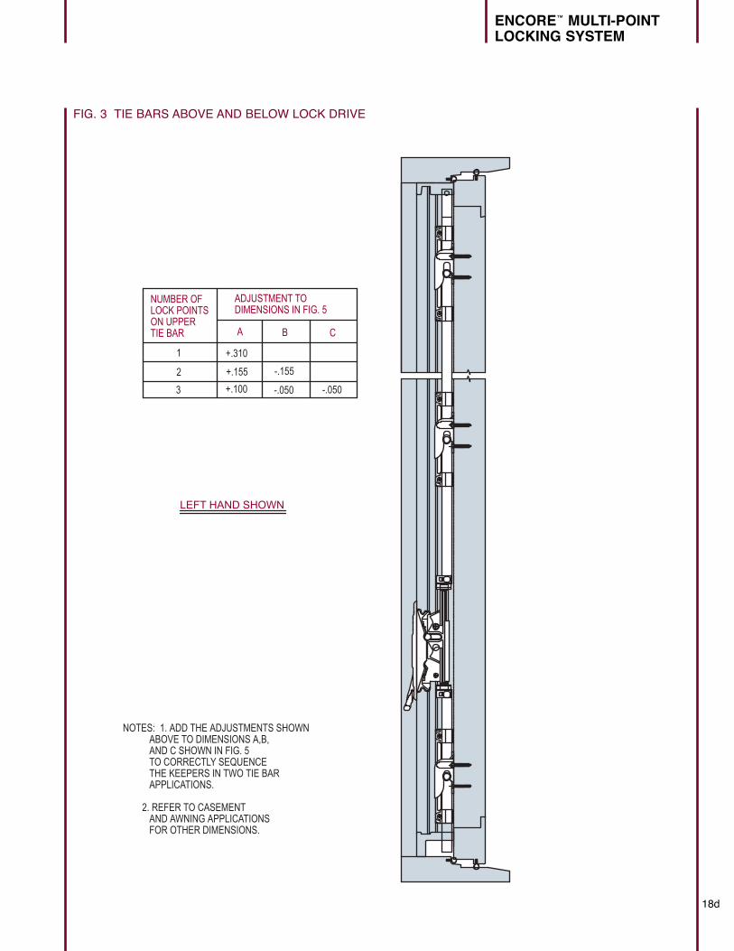
FIG. 3 TIE BARS ABOVE AND BELOW LOCK DRIVE
LEFT HAND SHOWN
NOTES: 1. ADD THE ADJUSTMENTS SHOWN ABOVE TO DIMENSIONS A,B, AND C SHOWN IN FIG. 5 TO CORRECTLY SEQUENCE THE KEEPERS IN TWO TIE BAR APPLICATIONS.
2. REFER TO CASEMENT AND AWNING APPLICATIONS FOR OTHER DIMENSIONS.
NUMBER OFLOCK POINTSON UPPER TIE BAR
ADJUSTMENT TO DIMENSIONS IN FIG. 5
A B C
+.310
+.155
+.100
-.155
-.050 -.050
1
2
3
ENCORE™ MULTI-POINT
LOCKING SYSTEM
18e
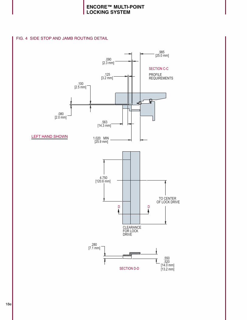
FIG. 4 SIDE STOP AND JAMB ROUTING DETAIL
TO CENTER OF LOCK DRIVE
CLEARANCEFOR LOCKDRIVE
D D
F
LEFT HAND SHOWN
[25.9 mm]1.020 MIN
[25.0 mm].985
[2.3 mm].090
[3.2 mm].125
[14.3 mm].563
[2.5 mm].100
[2.0 mm].080
SECTION C-C
PROFILEREQUIREMENTS
[120.6 mm]4.750
[7.1 mm].280
SECTION D-D[14.0 mm][13.2 mm]
.550
.520
18f
ENCORE™ MULTI-POINT
LOCKING SYSTEM
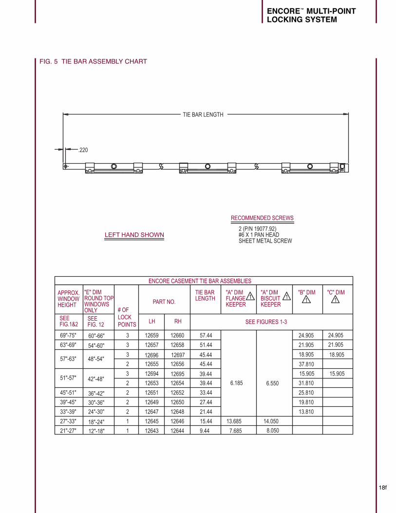
FIG. 5 TIE BAR ASSEMBLY CHART
.220
RECOMMENDED SCREWS
2 (P/N 19077.92)#6 X 1 PAN HEADSHEET METAL SCREW
F
LEFT HAND SHOWN
"A" DIMFLANGE KEEPER
"A" DIMBISCUIT KEEPER
1
6.550
14.050
8.050
TIE BAR LENGTH
3 12696 12697 45.44 18.905
3 12694 12695 39.44 15.905 15.905
37.810
"E" DIMROUND TOPWINDOWS ONLY
60"-66"
54"-60"
48"-54"
42"-48"
36"-42"
30"-36"
24"-30"
18"-24"
12"-18"
SEEFIG.1&2
SEE FIG. 12 SEE FIGURES 1-3
69"-75"
63"-69"
57"-63"
51"-57"
45"-51"
39"-45"
33"-39"
27"-33"
21"-27"
APPROX.WINDOWHEIGHT
3
3
2
2
2
2
2
1
1
# OF LOCKPOINTS
12659
12657
12655
12653
12651
12649
12647
12645
12643 12644
12646
12648
12650
12652
12654
12656
12658
12660
LH RH
PART NO.
57.44
51.44
45.44
39.44
33.44
27.44
21.44
15.44
9.44
TIE BARLENGTH 1
6.185
13.685
7.685
"B" DIM1
13.810
19.810
25.810
31.810
18.905
21.905
24.905
"C" DIM1
24.905
21.905
ENCORE CASEMENT TIE BAR ASSEMBLIES
ENCORE™ MULTI-POINT
LOCKING SYSTEM
18g
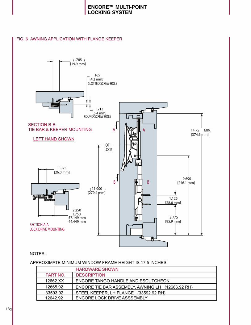
FIG. 6 AWNING APPLICATION WITH FLANGE KEEPER
[26.0 mm]1.025
[374.6 mm]14.75 MIN.
[5.4 mm].213
[4.2 mm].165
[19.9 mm]( .785 )
57.149 mm44.449 mm
2.2501.750
[28.6 mm]1.125
[279.4 mm]( 11.000 )
[95.9 mm]3.775
[246.1 mm]9.690
LEFT HAND SHOWN
ROUND SCREW HOLE
SLOTTED SCREW HOLE
12662.XX12665.9233593.9212642.92
PART NO.ENCORE TANGO HANDLE AND ESCUTCHEONENCORE TIE BAR ASSEMBLY, AWNING LH (12666.92 RH)STEEL KEEPER, LH FLANGE (33592.92 RH)ENCORE LOCK DRIVE ASSSEMBLY
DESCRIPTIONHARDWARE SHOWN
SECTION B-BTIE BAR & KEEPER MOUNTING
SECTION A-ALOCK DRIVE MOUNTING
NOTES:
APPROXIMATE MINIMUM WINDOW FRAME HEIGHT IS 17.5 INCHES.
OFLOCK
FIG. 6 AWNING APPLICATION WITH FLANGE
A A
BB
18h
ENCORE™ MULTI-POINT
LOCKING SYSTEM
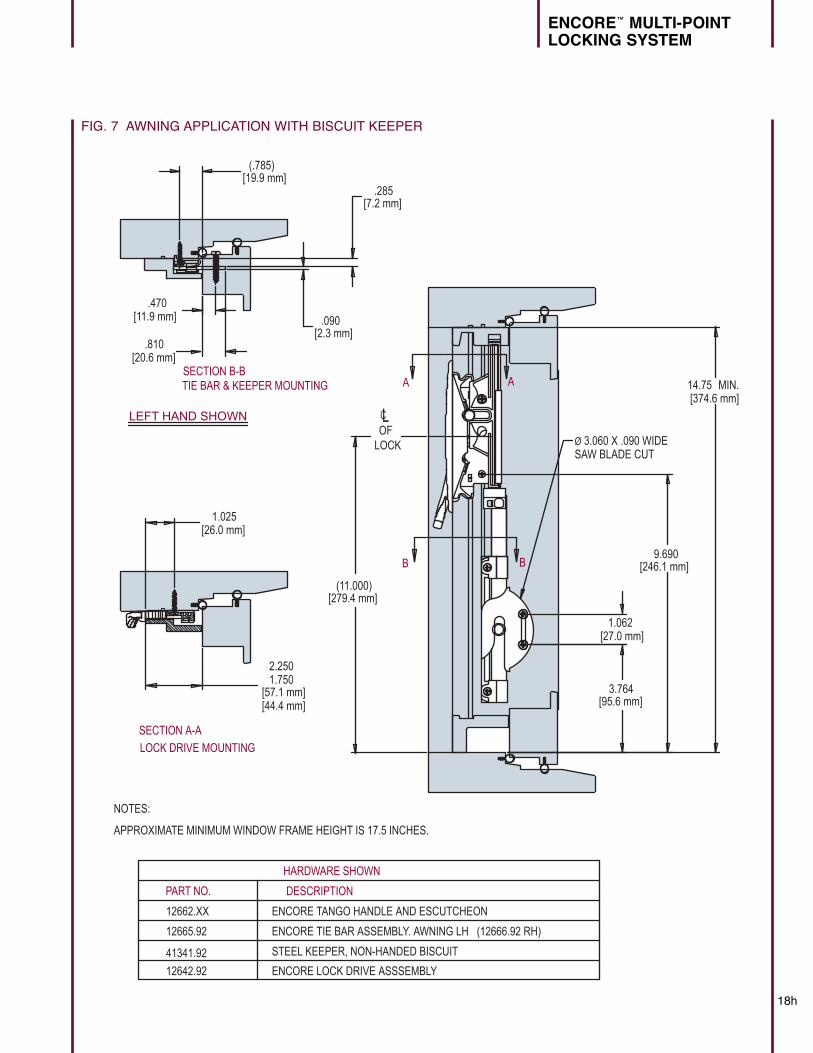
FIG. 7 AWNING APPLICATION WITH BISCUIT KEEPER
[26.0 mm]1.025
LEFT HAND SHOWN
[374.6 mm]14.75 MIN.
[11.9 mm].470
[20.6 mm].810
12662.XX
12665.92
41341.92
12642.92
PART NO.
ENCORE TANGO HANDLE AND ESCUTCHEON
ENCORE TIE BAR ASSEMBLY. AWNING LH (12666.92 RH)
STEEL KEEPER, NON-HANDED BISCUIT
ENCORE LOCK DRIVE ASSSEMBLY
DESCRIPTION
HARDWARE SHOWN
Ø 3.060 X .090 WIDESAW BLADE CUT
A A
BB
SECTION B-BTIE BAR & KEEPER MOUNTING
SECTION A-A
LOCK DRIVE MOUNTING
[57.1 mm][44.4 mm]
2.2501.750
NOTES:
APPROXIMATE MINIMUM WINDOW FRAME HEIGHT IS 17.5 INCHES.
OF LOCK
[27.0 mm]1.062
[279.4 mm](11.000)
[7.2 mm].285
[2.3 mm].090
[95.6 mm]3.764
[246.1 mm]9.690
[19.9 mm](.785)
LC
ENCORE™ MULTI-POINT
LOCKING SYSTEM
18i
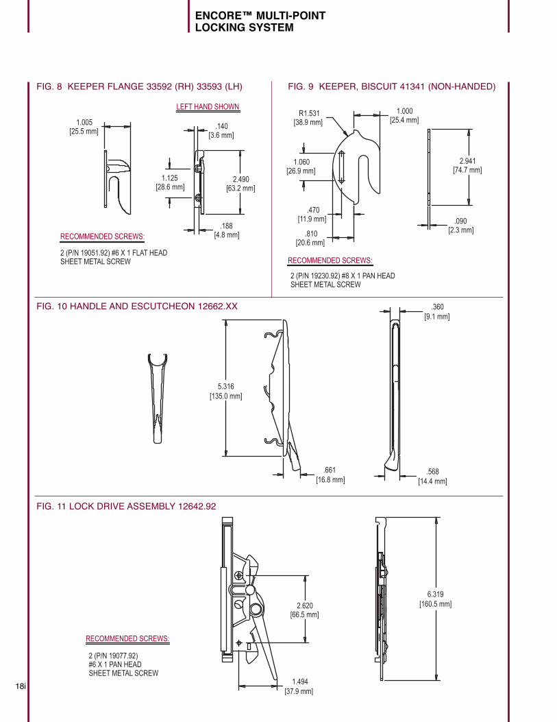
FIG. 8 KEEPER FLANGE 33592 (RH) 33593 (LH) FIG. 9 KEEPER, BISCUIT 41341 (NON-HANDED)
2 (P/N 19051.92) #6 X 1 FLAT HEAD SHEET METAL SCREW
2 (P/N 19230.92) #8 X 1 PAN HEADSHEET METAL SCREW
2
RECOMMENDED SCREWS: [4.8 mm].188
LEFT HAND SHOWN
[2.3 mm].090
[25.4 mm]1.000
[26.9 mm]1.060
[11.9 mm].470
[20.6 mm].810
RECOMMENDED SCREWS:
F
[38.9 mm]R1.531
FIG. 10 HANDLE AND ESCUTCHEON 12662.XX
F
[63.2 mm]2.490
[25.5 mm]1.005
[28.6 mm]1.125
[3.6 mm].140
[74.7 mm]2.941
[
[135.0 mm]5.316
[16.8 mm].661
[9.1 mm].360
[14.4 mm].568
FIG. 10 HANDLE AND ESCUTCHEON 12662.XX
2 (P/N 19077.92)#6 X 1 PAN HEAD SHEET METAL SCREW
P
[37.9 mm]1.494
[160.5 mm]6.319
[66.5 mm]2.620
RECOMMENDED SCREWS:
FIG. 11 LOCK DRIVE ASSEMBLY 12642.92
18j
ENCORE™ MULTI-POINT
LOCKING SYSTEM
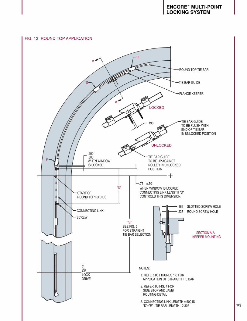
FIG. 12 ROUND TOP APPLICATION
A
A
.237 ROUND SCREW HOLE
.169 SLOTTED SCREW HOLE
"D"
.198
LOCKED
UNLOCKED
TIE BAR GUIDETO BE FLUSH WITH END OF TIE BARIN UNLOCKED POSITION
TIE BAR GUIDE TO BE UP AGAINST ROLLER IN UNLOCKED POSITION
START OF ROUND TOP RADIUS
.250
.000
.75 ±.50
F
G
H
ROUND TOP TIE BAR
TIE BAR GUIDE
FLANGE KEEPER
CONNECTING LINK
SCREW
NOTES:
1. REFER TO FIGURES 1-5 FOR APPLICATION OF STRAIGHT TIE BAR
2. REFER TO FIG. 4 FOR SIDE STOP AND JAMB ROUTING DETAIL
3. CONNECTING LINK LENGTH ±.500 IS "D"="E" - TIE BAR LENGTH - 2.305
SECTION A-AKEEPER MOUNTING
WHEN WINDOW IS LOCKED
WHEN WINDOW IS LOCKED.CONNECTING LINK LENGTH "D"CONTROLS THIS DIMENSION.
OF LOCKDRIVE
"E"SEE FIG. 5FOR STRAIGHT TIE BAR SELECTION
LC
18k
ENCORE™ MULTI-POINT
LOCKING SYSTEM
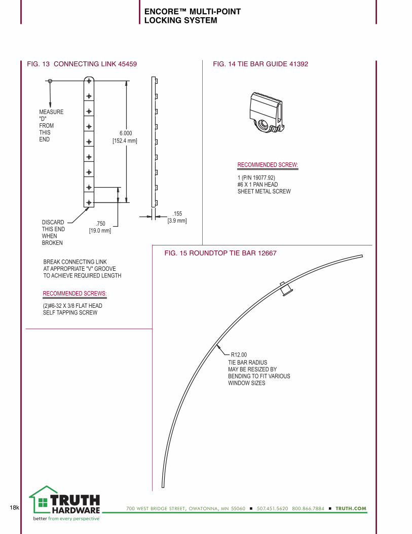
FIG. 13 CONNECTING LINK 45459 FIG. 14 TIE BAR GUIDE 41392
BREAK CONNECTING LINKAT APPROPRIATE "V" GROOVETO ACHIEVE REQUIRED LENGTH
P
(2)#6-32 X 3/8 FLAT HEADSELF TAPPING SCREW
1 (P/N 19077.92)#6 X 1 PAN HEADSHEET METAL SCREW
MEASURE "D"FROMTHIS END
TIE BAR RADIUS MAY BE RESIZED BY BENDING TO FIT VARIOUSWINDOW SIZES
1.990
FIG. 15 TIE BAR GUIDE 41392
FIG. 16 ROUNDTOP TIE BAR 12667
RECOMMENDED SCREW:
RECOMMENDED SCREWS:
6.000[152.4 mm]
[19.0 mm].750DISCARD
THIS ENDWHEN BROKEN
R12.00
[3.9 mm].155
FIG. 15 ROUNDTOP TIE BAR 12667
700 west bridge street, owatonna, mn 55060 � 507.451.5620 800.866.7884 � TRUTH.COM
1 (P/N 19077.92)#6 X 1 PAN HEADSHEET METAL SCREW
RECOMMENDED SCREW:


