
Version 1b- Sep06 By Dickson Sham (ME dept, HKPU)
A- 1
CATIA V5R16 surface modeling – Mouse
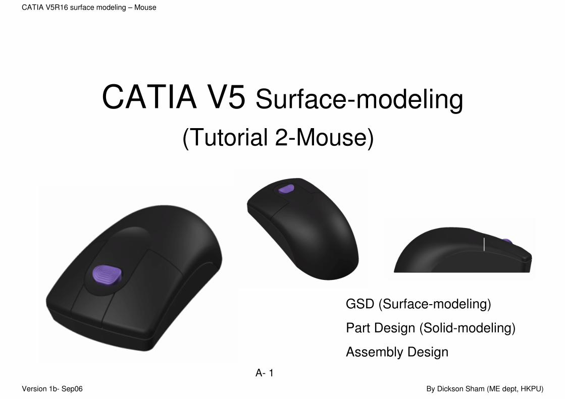
CATIA V5 Surface-modeling
(Tutorial 2-Mouse)
GSD (Surface-modeling)
Part Design (Solid-modeling)
Assembly Design
Version 1b- Sep06 By Dickson Sham (ME dept, HKPU)
A- 2
CATIA V5R16 surface modeling – Mouse
CATIA Surface-modeling
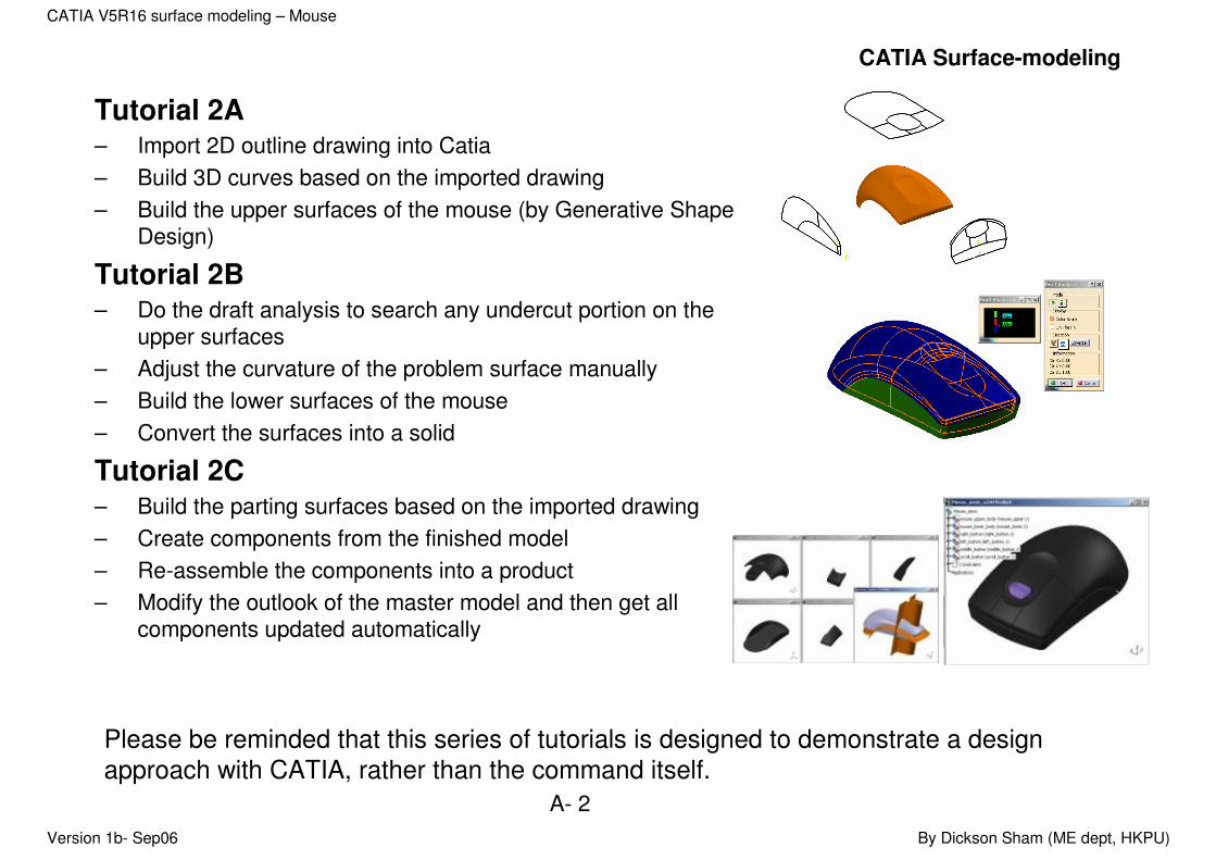
Tutorial 2A– Import 2D outline drawing into Catia
– Build 3D curves based on the imported drawing
– Build the upper surfaces of the mouse (by Generative Shape Design)
Tutorial 2B– Do the draft analysis to search any undercut portion on the
upper surfaces
– Adjust the curvature of the problem surface manually
– Build the lower surfaces of the mouse
– Convert the surfaces into a solid
Tutorial 2C– Build the parting surfaces based on the imported drawing
– Create components from the finished model
– Re-assemble the components into a product
– Modify the outlook of the master model and then get all components updated automatically
Please be reminded that this series of tutorials is designed to demonstrate a design
approach with CATIA, rather than the command itself.
Version 1b- Sep06 By Dickson Sham (ME dept, HKPU)
A- 3
CATIA V5R16 surface modeling – Mouse
Tutorial 2A
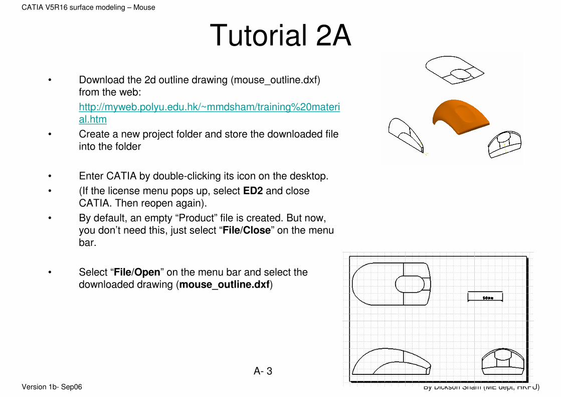
• Download the 2d outline drawing (mouse_outline.dxf) from the web:
http://myweb.polyu.edu.hk/~mmdsham/training%20material.htm
• Create a new project folder and store the downloaded file into the folder
• Enter CATIA by double-clicking its icon on the desktop.
• (If the license menu pops up, select ED2 and close CATIA. Then reopen again).
• By default, an empty “Product” file is created. But now, you don’t need this, just select “File/Close” on the menu bar.
• Select “File/Open” on the menu bar and select the downloaded drawing (mouse_outline.dxf)

Version 1b- Sep06 By Dickson Sham (ME dept, HKPU)
A- 4
CATIA V5R16 surface modeling – Mouse
Tutorial 2A
To confirm that the size of the
drawing is correct:-
• Click “Dimensions” icon;
• Click on the scale line of the drawing;
• Check if the displayed dimension is 50mm; If not, we need to enlarge or shrink the drawing into the correct size.
To copy and paste the drawing into 3D
space:-
• Multi-select all entities on the drawing, except the scale bar;
• Click “Copy” icon
Version 1b- Sep06 By Dickson Sham (ME dept, HKPU)
A- 5
CATIA V5R16 surface modeling – Mouse
Tutorial 2A
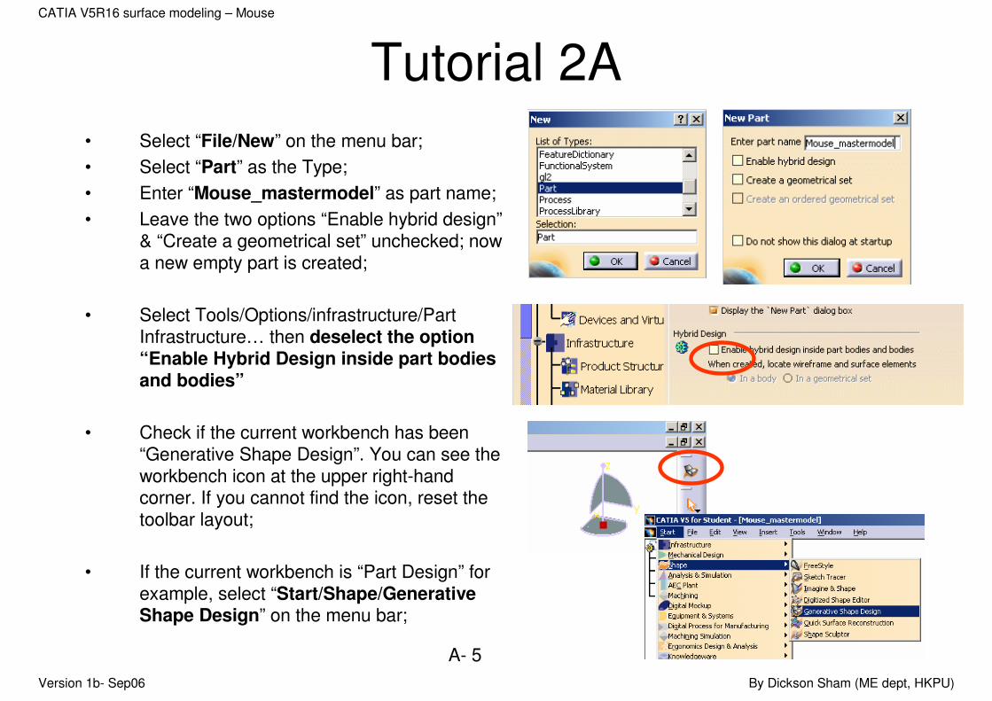
• Select “File/New” on the menu bar;
• Select “Part” as the Type;
• Enter “Mouse_mastermodel” as part name;
• Leave the two options “Enable hybrid design”& “Create a geometrical set” unchecked; now a new empty part is created;
• Select Tools/Options/infrastructure/Part Infrastructure… then deselect the option “Enable Hybrid Design inside part bodies and bodies”
• Check if the current workbench has been “Generative Shape Design”. You can see the workbench icon at the upper right-hand corner. If you cannot find the icon, reset the toolbar layout;
• If the current workbench is “Part Design” for example, select “Start/Shape/Generative Shape Design” on the menu bar;

Version 1b- Sep06 By Dickson Sham (ME dept, HKPU)
A- 6
CATIA V5R16 surface modeling – Mouse
Tutorial 2A
• Select “Insert/Geometrical Set…” on the menu bar; then click ok to confirm; (This geometrical set is going to store all three reference views of the mouse)
• Click “Sketch” icon and select xy plane;
• Click “Paste” icon to paste the drawing onto the xy plane;
• Click “Exit” icon to exit the sketcher mode. (Now “Sketch.1” is stored in “Geometrical Set.1”)
Version 1b- Sep06 By Dickson Sham (ME dept, HKPU)
A- 7
CATIA V5R16 surface modeling – Mouse
Tutorial 2A
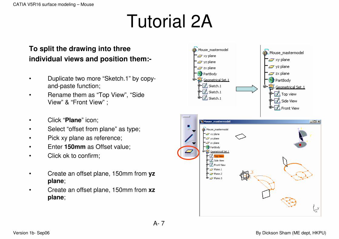
To split the drawing into three
individual views and position them:-
• Duplicate two more “Sketch.1” by copy-and-paste function;
• Rename them as “Top View”, “Side View” & “Front View” ;
• Click “Plane” icon;
• Select “offset from plane” as type;
• Pick xy plane as reference;
• Enter 150mm as Offset value;
• Click ok to confirm;
• Create an offset plane, 150mm from yzplane;
• Create an offset plane, 150mm from xzplane;
Version 1b- Sep06 By Dickson Sham (ME dept, HKPU)
A- 8
CATIA V5R16 surface modeling – Mouse
Tutorial 2A
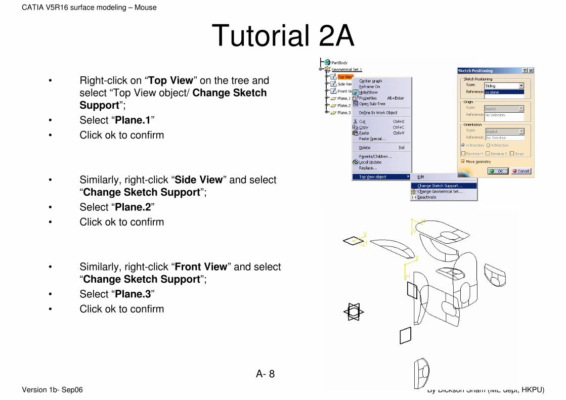
• Right-click on “Top View” on the tree and select “Top View object/ Change Sketch Support”;
• Select “Plane.1”
• Click ok to confirm
• Similarly, right-click “Side View” and select “Change Sketch Support”;
• Select “Plane.2”
• Click ok to confirm
• Similarly, right-click “Front View” and select “Change Sketch Support”;
• Select “Plane.3”
• Click ok to confirm

Version 1b- Sep06 By Dickson Sham (ME dept, HKPU)
A- 9
CATIA V5R16 surface modeling – Mouse
Tutorial 2A
• Double-click “Top View” sketch on the tree to edit;
• Select and delete the curves not related to the top view;
• Create a point at the rightmost of the shape (Click “point” icon, put the mouse cursor onto the rightmost arc, click to confirm its position when it is aligned on the same level as the center of the inner arc);
• Select all elements of the shape and click “Translate” icon;
Aligned
Version 1b- Sep06 By Dickson Sham (ME dept, HKPU)
A- 10
CATIA V5R16 surface modeling – Mouse
Tutorial 2A
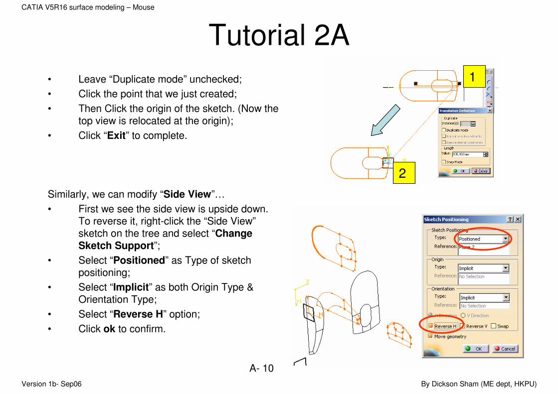
• Leave “Duplicate mode” unchecked;
• Click the point that we just created;
• Then Click the origin of the sketch. (Now the top view is relocated at the origin);
• Click “Exit” to complete.
Similarly, we can modify “Side View”…
• First we see the side view is upside down. To reverse it, right-click the “Side View”sketch on the tree and select “Change Sketch Support”;
• Select “Positioned” as Type of sketch positioning;
• Select “Implicit” as both Origin Type & Orientation Type;
• Select “Reverse H” option;
• Click ok to confirm.
1
2
Version 1b- Sep06 By Dickson Sham (ME dept, HKPU)
A- 11
CATIA V5R16 surface modeling – Mouse
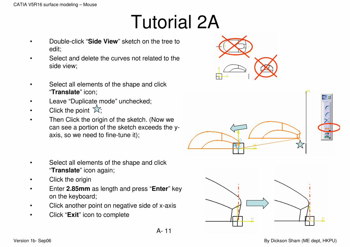
Tutorial 2A• Double-click “Side View” sketch on the tree to
edit;
• Select and delete the curves not related to the side view;
• Select all elements of the shape and click “Translate” icon;
• Leave “Duplicate mode” unchecked;
• Click the point ;
• Then Click the origin of the sketch. (Now we can see a portion of the sketch exceeds the y-axis, so we need to fine-tune it);
• Select all elements of the shape and click “Translate” icon again;
• Click the origin
• Enter 2.85mm as length and press “Enter” key on the keyboard;
• Click another point on negative side of x-axis
• Click “Exit” icon to complete

Version 1b- Sep06 By Dickson Sham (ME dept, HKPU)
A- 12
CATIA V5R16 surface modeling – Mouse
Tutorial 2ASimilarly, we can modify “Front View”…
• First we see the side view is orientated correctly. To adjust it, right-click the “Front View” sketch on the tree and select “Change Sketch Support”;
• Select “Positioned” as Type of sketch positioning;
• Select “Implicit” as both Origin Type & Orientation Type;
• Click ok to confirm.
• Double-click “Front View” sketch on the tree to edit;
• Select and delete the curves not related to the front view;
Top View
Side ViewFront View
Version 1b- Sep06 By Dickson Sham (ME dept, HKPU)
A- 13
CATIA V5R16 surface modeling – Mouse
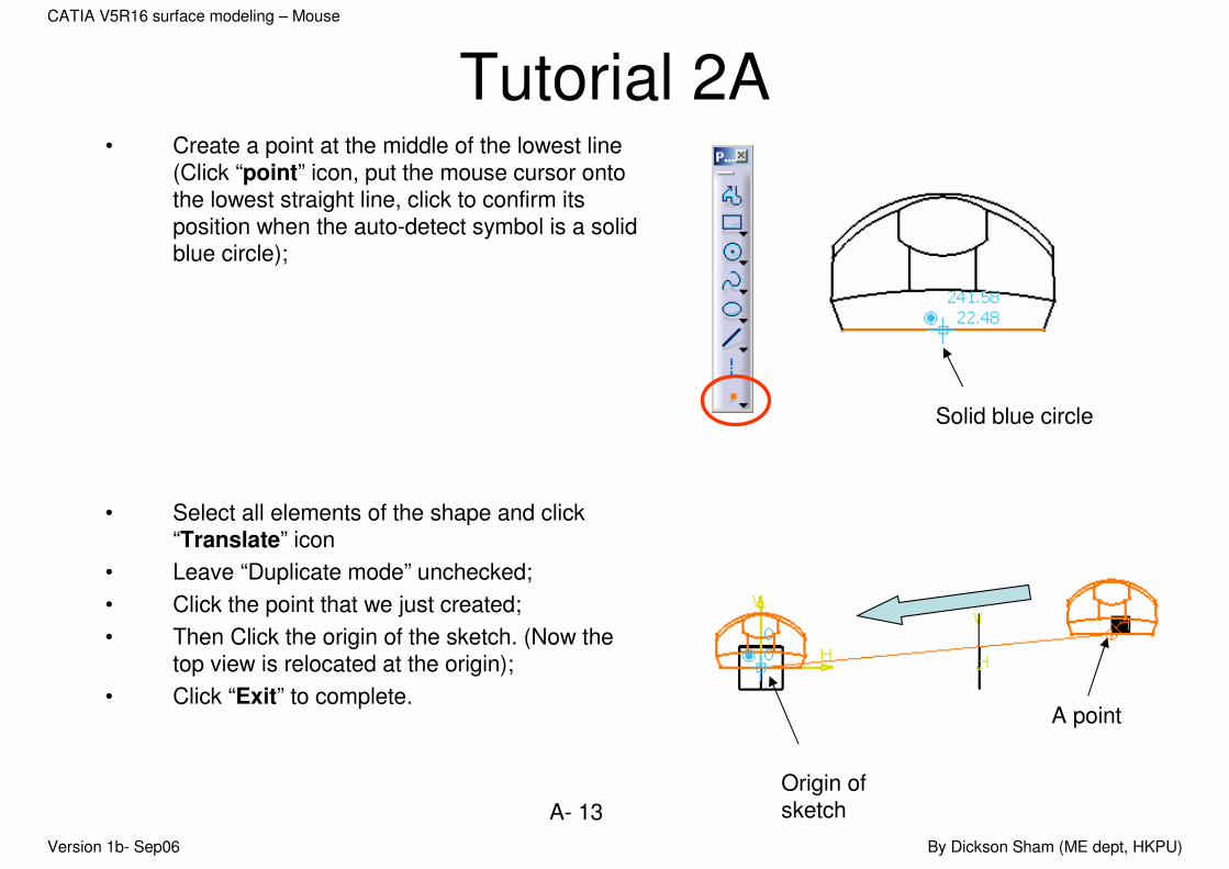
Tutorial 2A• Create a point at the middle of the lowest line
(Click “point” icon, put the mouse cursor onto the lowest straight line, click to confirm its position when the auto-detect symbol is a solid blue circle);
• Select all elements of the shape and click “Translate” icon
• Leave “Duplicate mode” unchecked;
• Click the point that we just created;
• Then Click the origin of the sketch. (Now the top view is relocated at the origin);
• Click “Exit” to complete.
Solid blue circle
Origin of sketch
A point
Version 1b- Sep06 By Dickson Sham (ME dept, HKPU)
A- 14
CATIA V5R16 surface modeling – Mouse
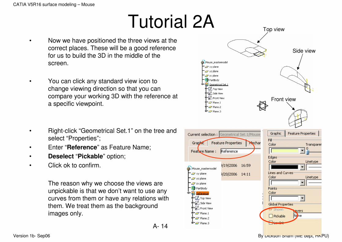
Tutorial 2A• Now we have positioned the three views at the
correct places. These will be a good reference for us to build the 3D in the middle of the screen.
• You can click any standard view icon to change viewing direction so that you can compare your working 3D with the reference at a specific viewpoint.
• Right-click “Geometrical Set.1” on the tree and select “Properties”;
• Enter “Reference” as Feature Name;
• Deselect “Pickable” option;
• Click ok to confirm.
The reason why we choose the views are unpickable is that we don’t want to use any curves from them or have any relations with them. We treat them as the background images only.
Top view
Side view
Front view
Version 1b- Sep06 By Dickson Sham (ME dept, HKPU)
A- 15
CATIA V5R16 surface modeling – Mouse
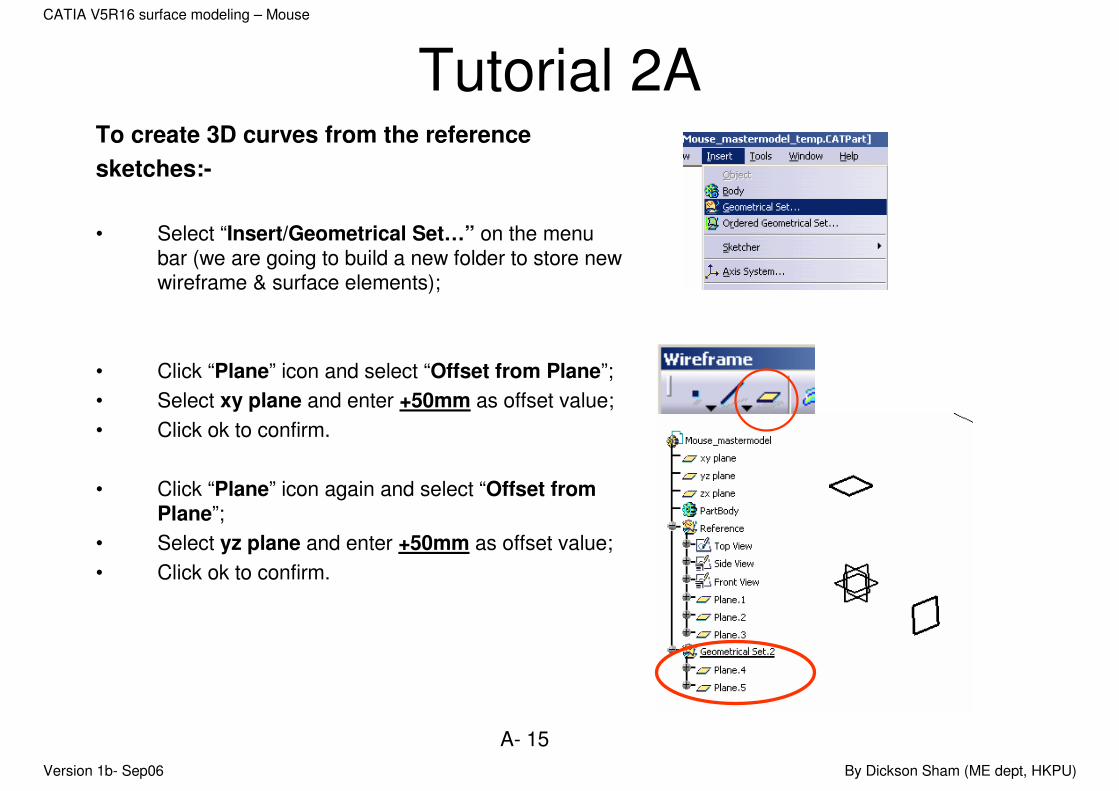
Tutorial 2ATo create 3D curves from the reference
sketches:-
• Select “Insert/Geometrical Set…” on the menu bar (we are going to build a new folder to store new wireframe & surface elements);
• Click “Plane” icon and select “Offset from Plane”;
• Select xy plane and enter +50mm as offset value;
• Click ok to confirm.
• Click “Plane” icon again and select “Offset from Plane”;
• Select yz plane and enter +50mm as offset value;
• Click ok to confirm.

Version 1b- Sep06 By Dickson Sham (ME dept, HKPU)
A- 16
CATIA V5R16 surface modeling – Mouse
Tutorial 2A• Click “Sketch” icon and select “Plane.4”;
• Draw an Arc (R90mm), with two ends symmetric about the x-axis and the arc is tangent to the y-axis;
• Reminded that the arc is a little longer than the reference;
• Click “Exit” icon to complete.
• Click an open area to deselect the Sketch (Sketch.4);
• Click “Sketch” icon and select “Plane.5”;
• Draw an Arc (R150mm), with two ends symmetric about the x-axis and the peak 11mm from the x-axis;
• Reminded that the arc should be a little bit longer than the reference;
• Click “Exit” icon to complete.
tangent
symmetric
symmetric
Version 1b- Sep06 By Dickson Sham (ME dept, HKPU)
A- 17
CATIA V5R16 surface modeling – Mouse
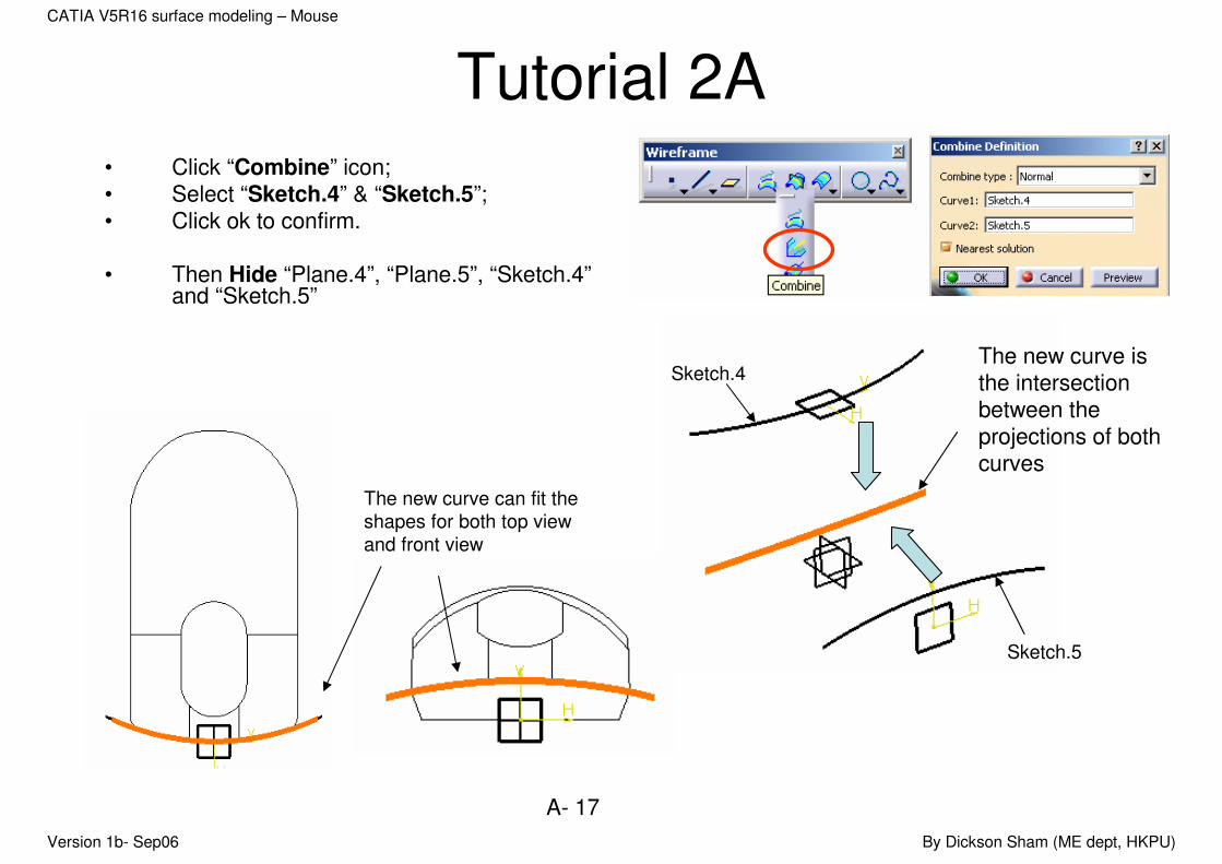
Tutorial 2A• Click “Combine” icon;• Select “Sketch.4” & “Sketch.5”;• Click ok to confirm.
• Then Hide “Plane.4”, “Plane.5”, “Sketch.4”and “Sketch.5”
The new curve is the intersection between the projections of both curves
Sketch.5
Sketch.4
The new curve can fit the
shapes for both top view
and front view

Version 1b- Sep06 By Dickson Sham (ME dept, HKPU)
A- 18
CATIA V5R16 surface modeling – Mouse
Tutorial 2A
• Click “Plane” icon and select “Offset from Plane”;
• Select zx plane and enter +30.5mm as offset value;
• Click ok to confirm.
• Click “Sketch” icon and select the new plane “Plane.6”;
• Draw two arcs as shown;
• Reminded that two arcs must be tangent to each other; one end of the small arc is touching the x-axis; one end of the bigger arc is just near y-axis;
• Click “Exit” icon to complete.
Plane.6
Version 1b- Sep06 By Dickson Sham (ME dept, HKPU)
A- 19
CATIA V5R16 surface modeling – Mouse
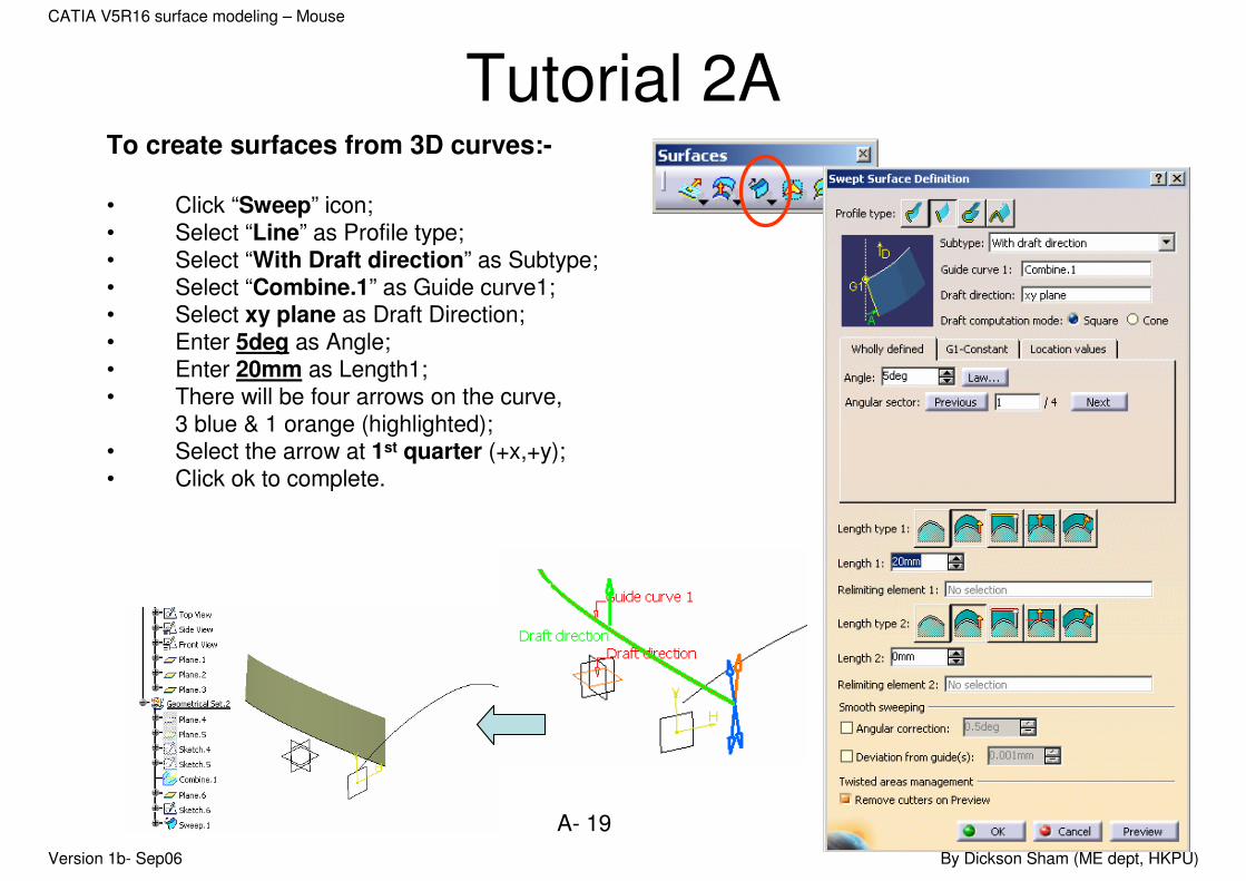
Tutorial 2ATo create surfaces from 3D curves:-
• Click “Sweep” icon;• Select “Line” as Profile type;• Select “With Draft direction” as Subtype;• Select “Combine.1” as Guide curve1;• Select xy plane as Draft Direction;• Enter 5deg as Angle;• Enter 20mm as Length1;• There will be four arrows on the curve,
3 blue & 1 orange (highlighted);• Select the arrow at 1st quarter (+x,+y);• Click ok to complete.
Version 1b- Sep06 By Dickson Sham (ME dept, HKPU)
A- 20
CATIA V5R16 surface modeling – Mouse
Tutorial 2A
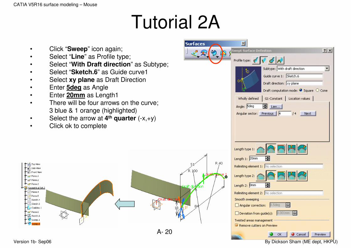
• Click “Sweep” icon again;• Select “Line” as Profile type;• Select “With Draft direction” as Subtype;• Select “Sketch.6” as Guide curve1• Select xy plane as Draft Direction• Enter 5deg as Angle• Enter 20mm as Length1• There will be four arrows on the curve;
3 blue & 1 orange (highlighted)• Select the arrow at 4th quarter (-x,+y)• Click ok to complete

Version 1b- Sep06 By Dickson Sham (ME dept, HKPU)
A- 21
CATIA V5R16 surface modeling – Mouse
Tutorial 2ATo duplicate a surface by mirroring:-
• Click “Symmetry” icon;
• Select “Sweep.2” as Element;
• Select “zx plane” as Reference;
• Click ok to complete.
To add a fillet between two surfaces:-
• Click “Shape Fillet” icon;
• Select surfaces “Sweep.1” & “Sweep.2”;
• Click the red arrows on the surfaces if they are not pointing inwards;
• Enter 5mm as Radius;
• Click ok to complete.

Version 1b- Sep06 By Dickson Sham (ME dept, HKPU)
A- 22
CATIA V5R16 surface modeling – Mouse
Tutorial 2A
• Click “Shape Fillet” icon;
• Select surfaces “Fillet.1” & “Symmetry.1”;
• Click the red arrows on the surfaces if they are not pointing inwards;
• Enter 5mm as Radius;
• Click ok to complete
To duplicate a 3D curve by
translation:-
• Click “Translate” icon;
• Select “Combine.1” as Element;
• Select “xy plane” as Direction;
• Enter 3.5mm as Distance;
• Click ok to complete.
Version 1b- Sep06 By Dickson Sham (ME dept, HKPU)
A- 23
CATIA V5R16 surface modeling – Mouse
Tutorial 2A
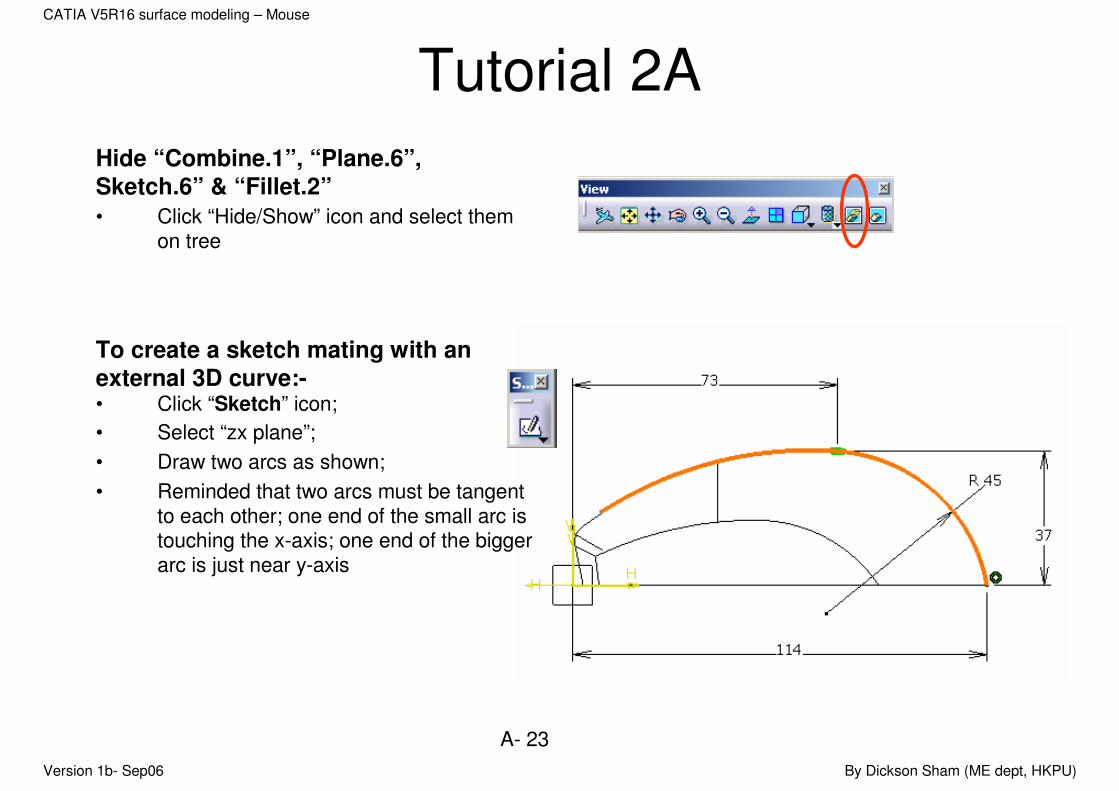
Hide “Combine.1”, “Plane.6”,
Sketch.6” & “Fillet.2”
• Click “Hide/Show” icon and select them on tree
To create a sketch mating with an
external 3D curve:-• Click “Sketch” icon;
• Select “zx plane”;
• Draw two arcs as shown;
• Reminded that two arcs must be tangent to each other; one end of the small arc is touching the x-axis; one end of the bigger arc is just near y-axis

Version 1b- Sep06 By Dickson Sham (ME dept, HKPU)
A- 24
CATIA V5R16 surface modeling – Mouse
Tutorial 2A• Click “intersect 3D elements” icon;
• Select “Translate.1” on tree or Direct-click the curve;
• Select the intersection point and click “Construction/Standard element” icon (The point shape will be changed from a cross to a point);
• Add a coincidence constraint between the endpoint of the bigger arc and the intersection point.
• Click ok to complete
The arc touches
“Translate.1” after we’ve
added a coincidence
constraint
Version 1b- Sep06 By Dickson Sham (ME dept, HKPU)
A- 25
CATIA V5R16 surface modeling – Mouse
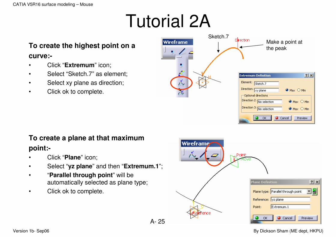
Tutorial 2ATo create the highest point on a
curve:-
• Click “Extremum” icon;
• Select “Sketch.7” as element;
• Select xy plane as direction;
• Click ok to complete.
To create a plane at that maximum
point:-
• Click “Plane” icon;
• Select “yz plane” and then “Extremum.1”;
• “Parallel through point” will be automatically selected as plane type;
• Click ok to complete.
Make a point at
the peak
Sketch.7
Version 1b- Sep06 By Dickson Sham (ME dept, HKPU)
A- 26
CATIA V5R16 surface modeling – Mouse
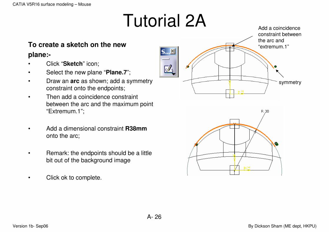
Tutorial 2ATo create a sketch on the new
plane:-
• Click “Sketch” icon;
• Select the new plane “Plane.7”;
• Draw an arc as shown; add a symmetry constraint onto the endpoints;
• Then add a coincidence constraint between the arc and the maximum point “Extremum.1”;
• Add a dimensional constraint R38mm onto the arc;
• Remark: the endpoints should be a little bit out of the background image
• Click ok to complete.
Add a coincidence
constraint between
the arc and
“extremum.1”
symmetry
Version 1b- Sep06 By Dickson Sham (ME dept, HKPU)
A- 27
CATIA V5R16 surface modeling – Mouse
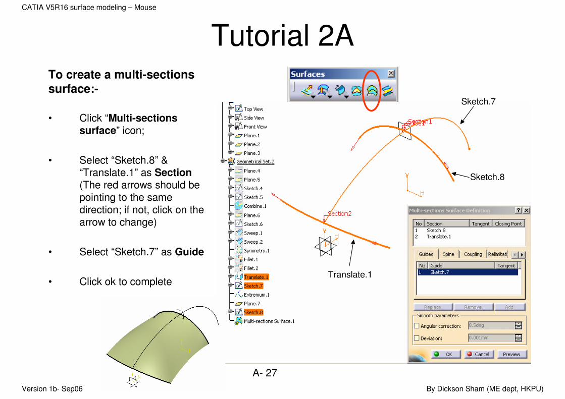
Tutorial 2ATo create a multi-sections
surface:-
• Click “Multi-sections surface” icon;
• Select “Sketch.8” & “Translate.1” as Section(The red arrows should be pointing to the same direction; if not, click on the arrow to change)
• Select “Sketch.7” as Guide
• Click ok to completeTranslate.1
Sketch.8
Sketch.7

Version 1b- Sep06 By Dickson Sham (ME dept, HKPU)
A- 28
CATIA V5R16 surface modeling – Mouse
Tutorial 2ATo Trim surfaces and form a joined
surface:-
• Show “Fillet.2” on the tree;
• Click “Trim” icon
• Select surfaces “Fillet.2” & ‘Multi-sections Surface.1”
• Click the option “Other side/next element” & “Other side/previous element” to obtain the result as shown on the right.
• Click ok to complete
Fillet.2
Multi-sections
Surface.1
Version 1b- Sep06 By Dickson Sham (ME dept, HKPU)
A- 29
CATIA V5R16 surface modeling – Mouse
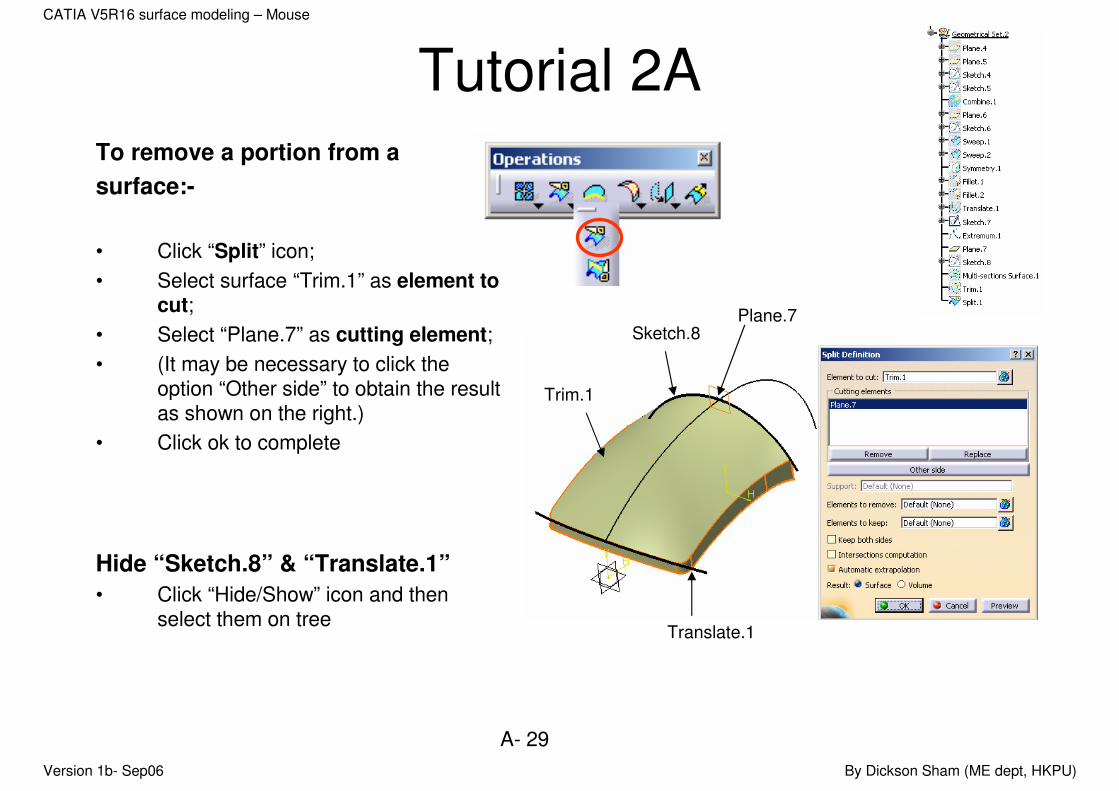
Tutorial 2ATo remove a portion from a
surface:-
• Click “Split” icon;
• Select surface “Trim.1” as element to cut;
• Select “Plane.7” as cutting element;
• (It may be necessary to click the option “Other side” to obtain the result as shown on the right.)
• Click ok to complete
Hide “Sketch.8” & “Translate.1”
• Click “Hide/Show” icon and then select them on tree
Trim.1
Plane.7Sketch.8
Translate.1
Version 1b- Sep06 By Dickson Sham (ME dept, HKPU)
A- 30
CATIA V5R16 surface modeling – Mouse
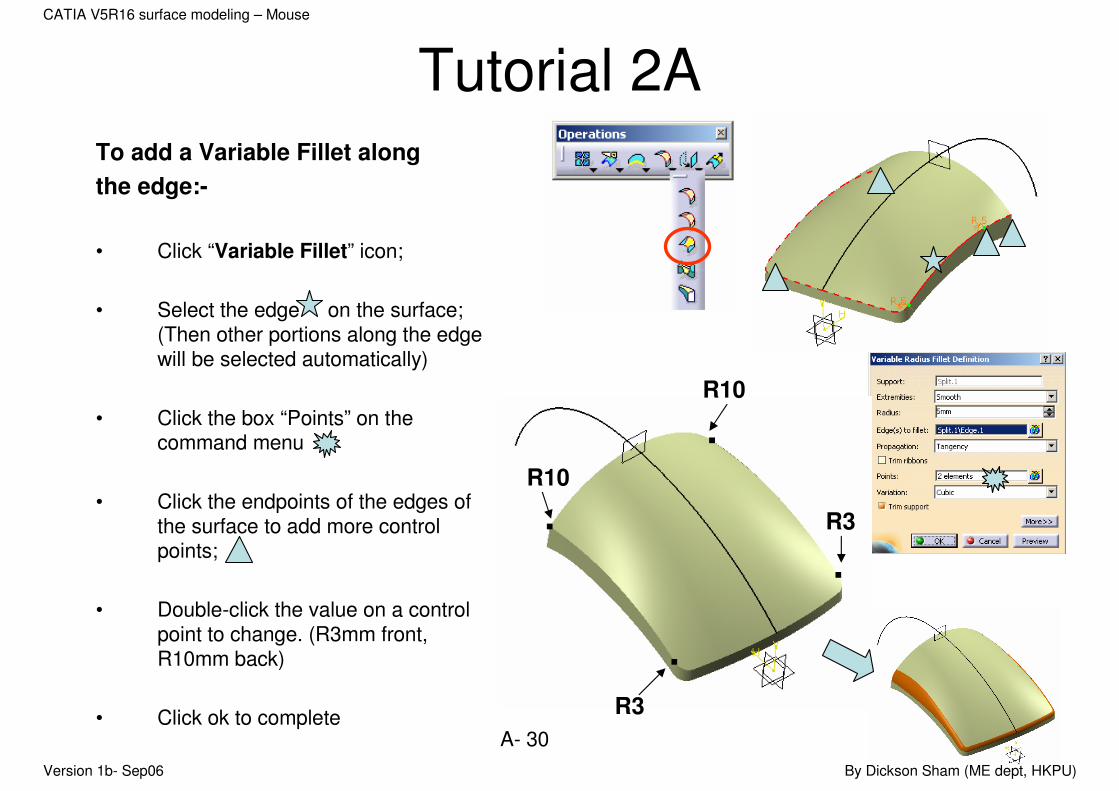
Tutorial 2ATo add a Variable Fillet along
the edge:-
• Click “Variable Fillet” icon;
• Select the edge on the surface; (Then other portions along the edge will be selected automatically)
• Click the box “Points” on the command menu
• Click the endpoints of the edges of the surface to add more control points;
• Double-click the value on a control point to change. (R3mm front, R10mm back)
• Click ok to complete
R10
R3
R3
R10
Version 1b- Sep06 By Dickson Sham (ME dept, HKPU)
A- 31
CATIA V5R16 surface modeling – Mouse
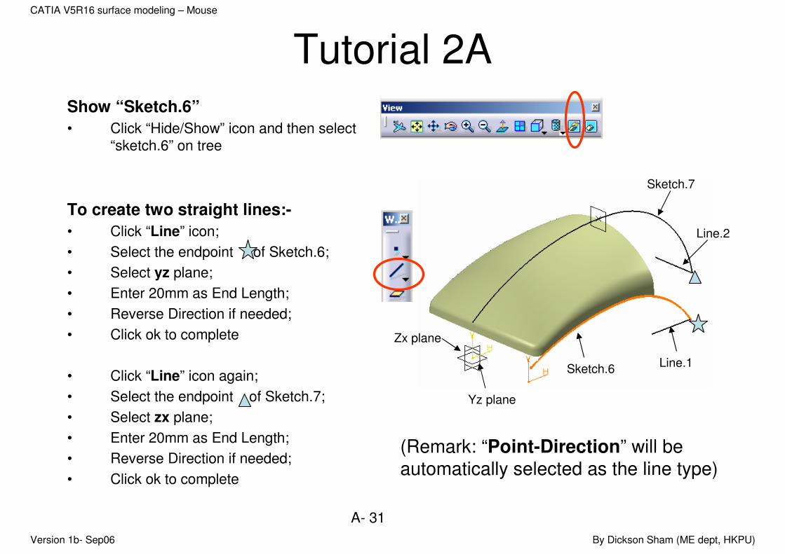
Tutorial 2AShow “Sketch.6”
• Click “Hide/Show” icon and then select “sketch.6” on tree
To create two straight lines:-
• Click “Line” icon;
• Select the endpoint of Sketch.6;
• Select yz plane;
• Enter 20mm as End Length;
• Reverse Direction if needed;
• Click ok to complete
• Click “Line” icon again;
• Select the endpoint of Sketch.7;
• Select zx plane;
• Enter 20mm as End Length;
• Reverse Direction if needed;
• Click ok to complete
Sketch.6
Line.2
Line.1
Sketch.7
Zx plane
Yz plane
(Remark: “Point-Direction” will be
automatically selected as the line type)
Version 1b- Sep06 By Dickson Sham (ME dept, HKPU)
A- 32
CATIA V5R16 surface modeling – Mouse
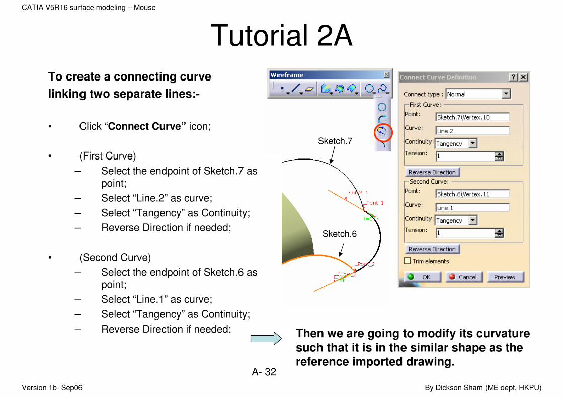
Tutorial 2ATo create a connecting curve
linking two separate lines:-
• Click “Connect Curve” icon;
• (First Curve)
– Select the endpoint of Sketch.7 as point;
– Select “Line.2” as curve;
– Select “Tangency” as Continuity;
– Reverse Direction if needed;
• (Second Curve)
– Select the endpoint of Sketch.6 as point;
– Select “Line.1” as curve;
– Select “Tangency” as Continuity;
– Reverse Direction if needed;
Sketch.7
Sketch.6
Then we are going to modify its curvature
such that it is in the similar shape as the reference imported drawing.

Version 1b- Sep06 By Dickson Sham (ME dept, HKPU)
A- 33
CATIA V5R16 surface modeling – Mouse
Tutorial 2A• Click “Top View” icon and now we can
see the reference top view;
• Enter 1.7 as tension of 1st Curve
• Enter 0.4 as tension of 2nd Curve
• Click ok to confirm

Version 1b- Sep06 By Dickson Sham (ME dept, HKPU)
A- 34
CATIA V5R16 surface modeling – Mouse
Tutorial 2ATo duplicate curves about a mirror
plane:-
• Click “Symmetry” icon;
• Select “Sketch.6” as element;
• Select “zx plane” as reference;
• Click ok to complete.
• Similarly, Click “Symmetry” icon again;
• Select “Connect.1” as element;
• Select “zx plane” as reference;
• Click ok to complete.
Sketch.6Connect.1
Zx plane
Version 1b- Sep06 By Dickson Sham (ME dept, HKPU)
A- 35
CATIA V5R16 surface modeling – Mouse
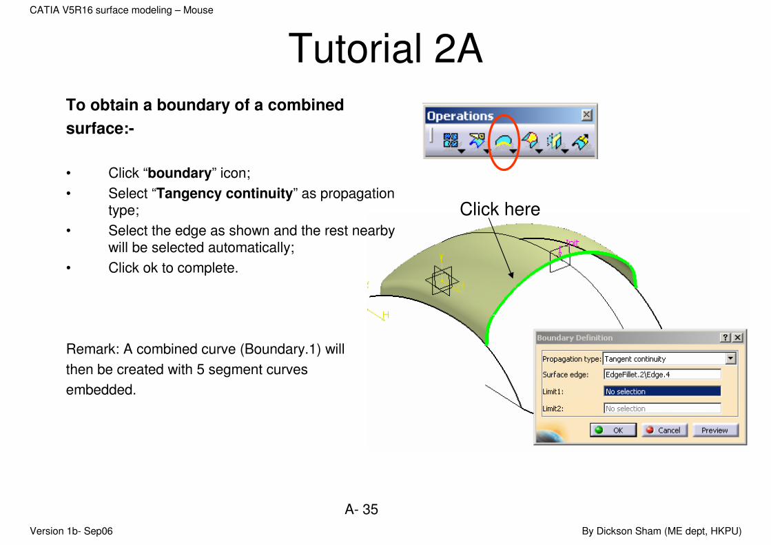
Tutorial 2ATo obtain a boundary of a combined
surface:-
• Click “boundary” icon;
• Select “Tangency continuity” as propagation type;
• Select the edge as shown and the rest nearby will be selected automatically;
• Click ok to complete.
Remark: A combined curve (Boundary.1) will
then be created with 5 segment curves
embedded.
Click here

Version 1b- Sep06 By Dickson Sham (ME dept, HKPU)
A- 36
CATIA V5R16 surface modeling – Mouse
Tutorial 2ATo join two curves into one:-
• Click “Join” icon;
• Select “Connect.1” & “ Symmetry.3”;
• Click ok to complete.
Boundary.1
Symmetry.2
Connect.1
Symmetry.3
Sketch.6
Version 1b- Sep06 By Dickson Sham (ME dept, HKPU)
A- 37
CATIA V5R16 surface modeling – Mouse
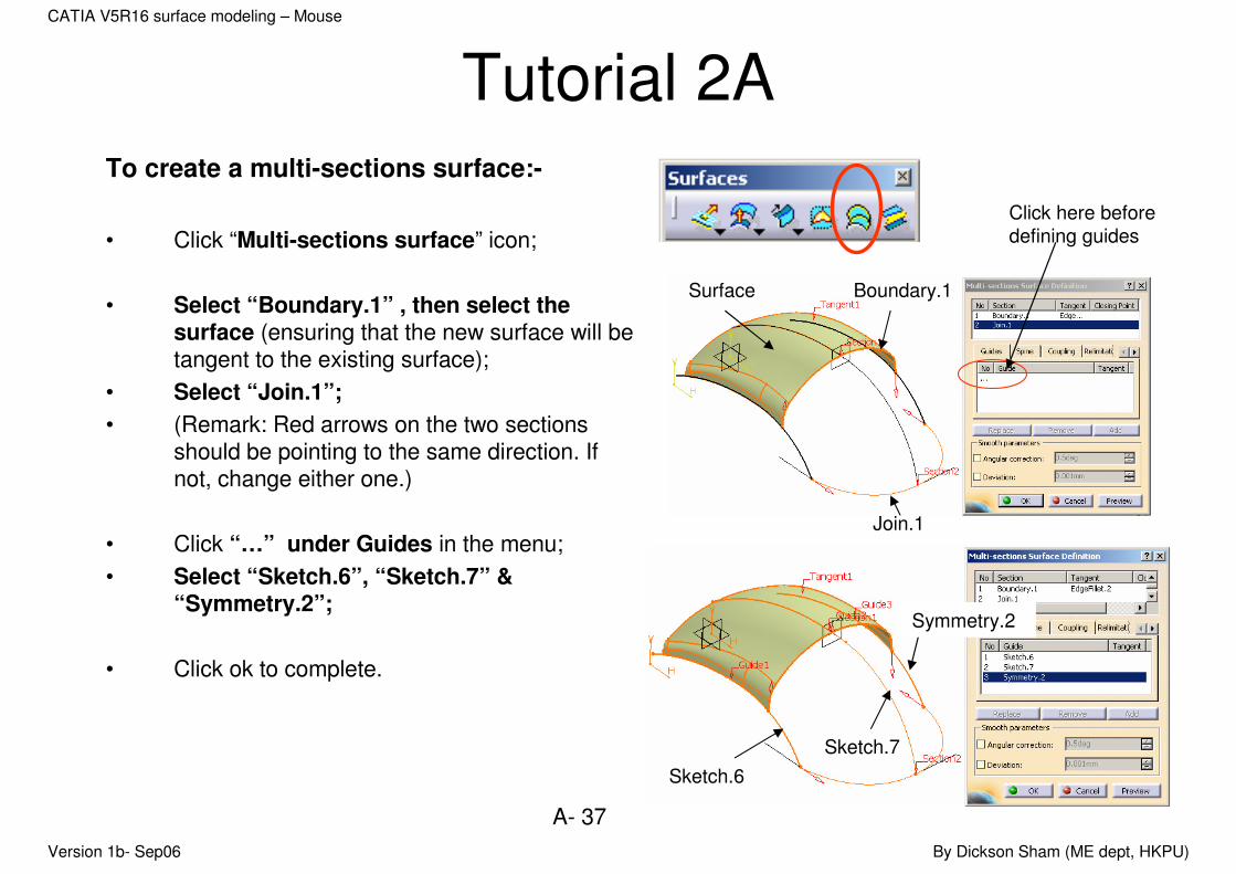
Tutorial 2ATo create a multi-sections surface:-
• Click “Multi-sections surface” icon;
• Select “Boundary.1” , then select the surface (ensuring that the new surface will be tangent to the existing surface);
• Select “Join.1”;
• (Remark: Red arrows on the two sections should be pointing to the same direction. If not, change either one.)
• Click “…” under Guides in the menu;
• Select “Sketch.6”, “Sketch.7” & “Symmetry.2”;
• Click ok to complete.
Symmetry.2
Sketch.6
Sketch.7
Join.1
Boundary.1
Click here before
defining guides
Surface
Version 1b- Sep06 By Dickson Sham (ME dept, HKPU)
A- 38
CATIA V5R16 surface modeling – Mouse
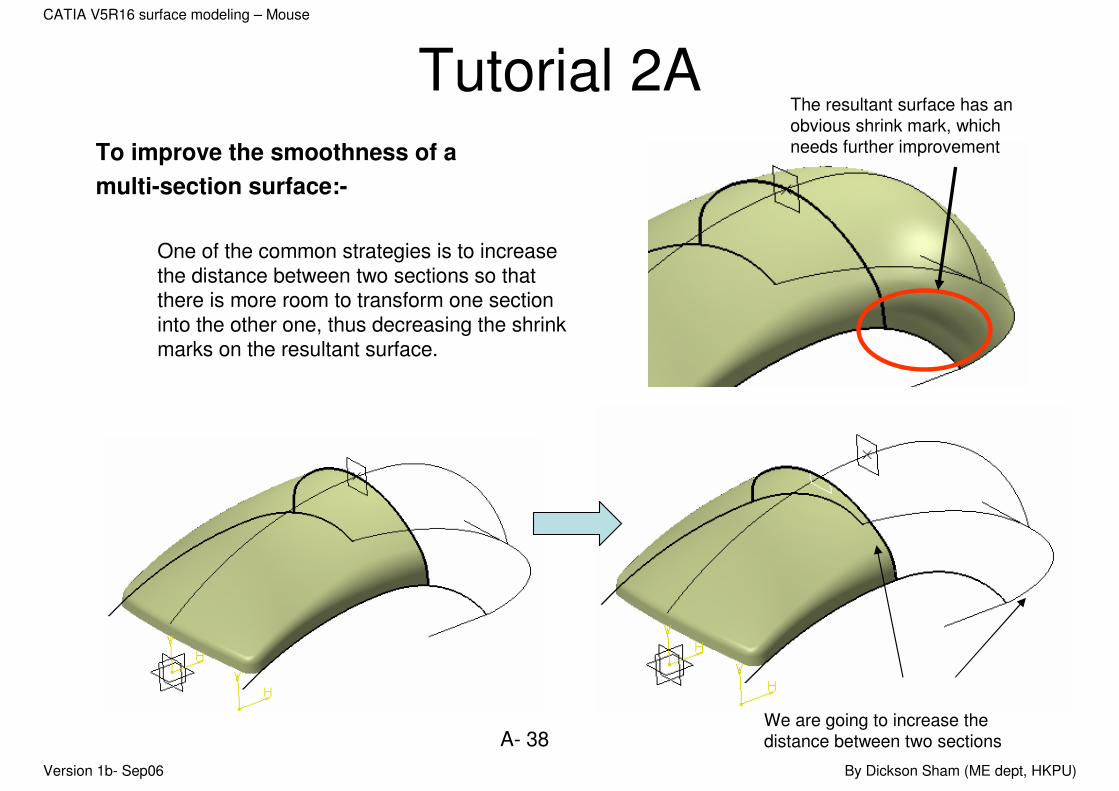
Tutorial 2ATo improve the smoothness of a
multi-section surface:-
One of the common strategies is to increase the distance between two sections so that there is more room to transform one section into the other one, thus decreasing the shrink marks on the resultant surface.
The resultant surface has an
obvious shrink mark, which
needs further improvement
We are going to increase the
distance between two sections
Version 1b- Sep06 By Dickson Sham (ME dept, HKPU)
A- 39
CATIA V5R16 surface modeling – Mouse
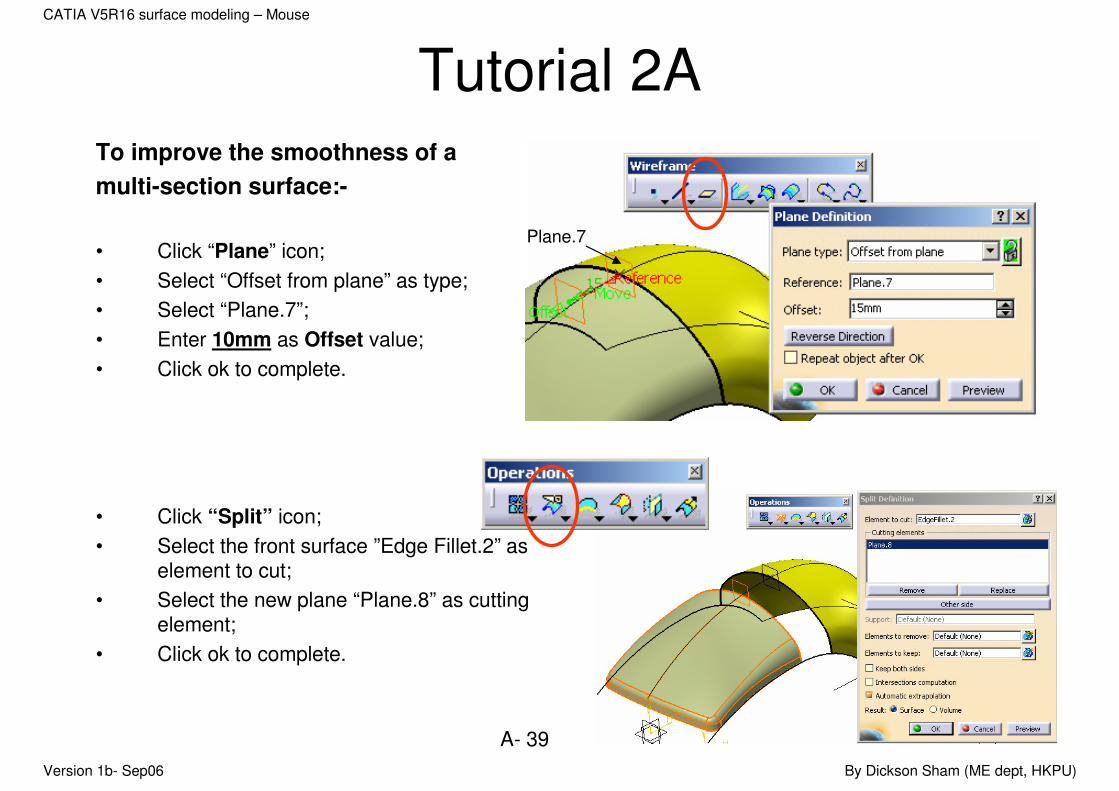
Tutorial 2ATo improve the smoothness of a
multi-section surface:-
• Click “Plane” icon;
• Select “Offset from plane” as type;
• Select “Plane.7”;
• Enter 10mm as Offset value;
• Click ok to complete.
• Click “Split” icon;
• Select the front surface ”Edge Fillet.2” as element to cut;
• Select the new plane “Plane.8” as cutting element;
• Click ok to complete.
Plane.7
Version 1b- Sep06 By Dickson Sham (ME dept, HKPU)
A- 40
CATIA V5R16 surface modeling – Mouse
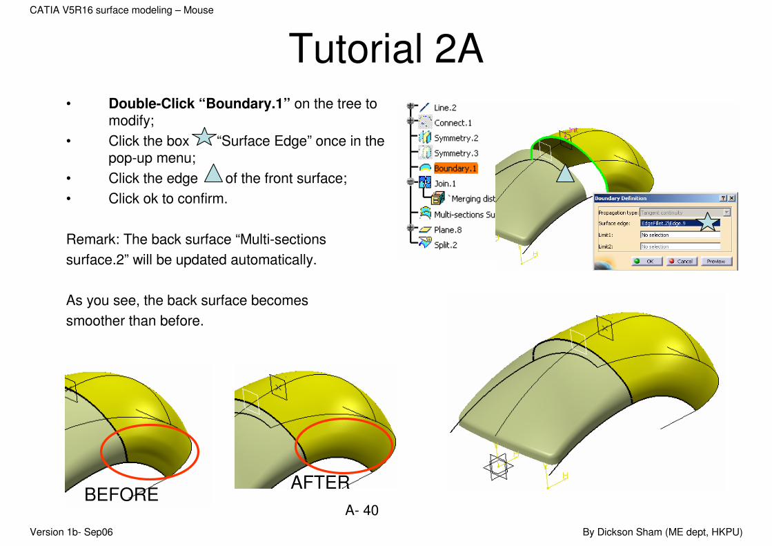
Tutorial 2A• Double-Click “Boundary.1” on the tree to
modify;
• Click the box “Surface Edge” once in the pop-up menu;
• Click the edge of the front surface;
• Click ok to confirm.
Remark: The back surface “Multi-sections
surface.2” will be updated automatically.
As you see, the back surface becomes
smoother than before.
BEFOREAFTER

Version 1b- Sep06 By Dickson Sham (ME dept, HKPU)
A- 41
CATIA V5R16 surface modeling – Mouse
Tutorial 2ATo auto-sort the tree:-
After modifying the position of the front section, the back surface is updated but the tree is not in logical sequence. Although it is not a must and does not affect the final result, keeping the tree in a correct order can help us modify the model more easily in future.
e.g. “Split.2” should appear before “Boundary.1”
• Right-Click “Geometrical Set.2”
• Select “Geometrical Set.2 Object/ Autosort”
• Then the tree will be re-ordered in a logical way.
Version 1b- Sep06 By Dickson Sham (ME dept, HKPU)
A- 42
CATIA V5R16 surface modeling – Mouse
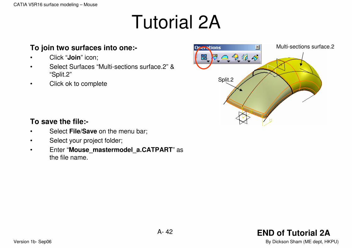
Tutorial 2ATo join two surfaces into one:-
• Click “Join” icon;
• Select Surfaces “Multi-sections surface.2” & “Split.2”
• Click ok to complete
To save the file:-
• Select File/Save on the menu bar;
• Select your project folder;
• Enter “Mouse_mastermodel_a.CATPART” as the file name.
Multi-sections surface.2
Split.2
END of Tutorial 2A

Version 1b- Sep06 By Dickson Sham (ME dept, HKPU)
A- 43
CATIA V5R16 surface modeling – Mouse
Tutorial 2BWe continue to build the skin of the upper part. After that, we
need to check if the whole skin can meet the required shape and has no undercut portion…
• Reopen the file “Mouse_mastermodel_a.CATPART” ;
• Ensure that the current workbench is “Generative Shape Design”;
• Click “Front View” icon to check the front view;
• Click “Right View” icon to check the right view;
• Click “Top View” icon to check the top view;
(Remark: the surface should match the three reference views)
Front
Right
Top
Version 1b- Sep06 By Dickson Sham (ME dept, HKPU)
A- 44
CATIA V5R16 surface modeling – Mouse
Sketch9
join2
Xy plane
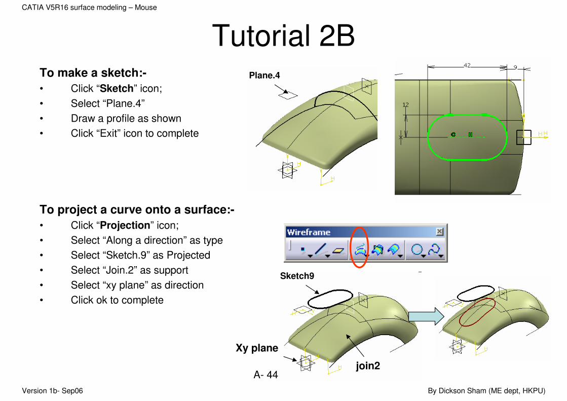
Tutorial 2BTo make a sketch:-
• Click “Sketch” icon;
• Select “Plane.4”
• Draw a profile as shown
• Click “Exit” icon to complete
To project a curve onto a surface:-
• Click “Projection” icon;
• Select “Along a direction” as type
• Select “Sketch.9” as Projected
• Select “Join.2” as support
• Select “xy plane” as direction
• Click ok to complete
Plane.4
Version 1b- Sep06 By Dickson Sham (ME dept, HKPU)
A- 45
CATIA V5R16 surface modeling – Mouse
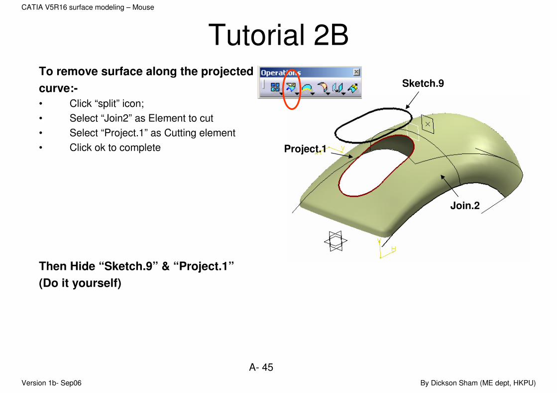
Tutorial 2BTo remove surface along the projected
curve:-
• Click “split” icon;
• Select “Join2” as Element to cut
• Select “Project.1” as Cutting element
• Click ok to complete
Then Hide “Sketch.9” & “Project.1”
(Do it yourself)
Join.2
Project.1
Sketch.9
Version 1b- Sep06 By Dickson Sham (ME dept, HKPU)
A- 46
CATIA V5R16 surface modeling – Mouse
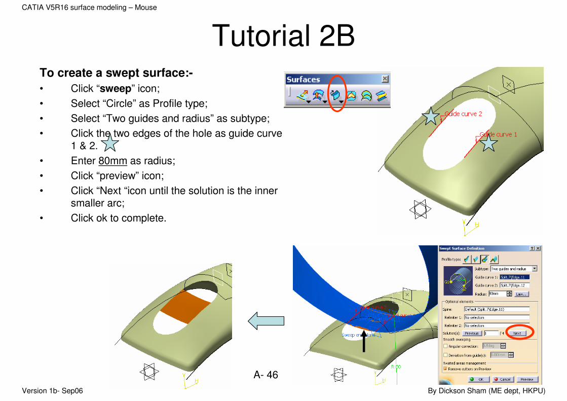
Tutorial 2BTo create a swept surface:-
• Click “sweep” icon;
• Select “Circle” as Profile type;
• Select “Two guides and radius” as subtype;
• Click the two edges of the hole as guide curve 1 & 2.
• Enter 80mm as radius;
• Click “preview” icon;
• Click “Next “icon until the solution is the inner smaller arc;
• Click ok to complete.
Version 1b- Sep06 By Dickson Sham (ME dept, HKPU)
A- 47
CATIA V5R16 surface modeling – Mouse
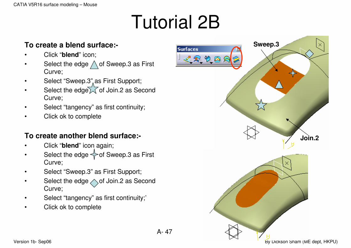
Tutorial 2BTo create a blend surface:-
• Click “blend” icon;
• Select the edge of Sweep.3 as First Curve;
• Select “Sweep.3” as First Support;
• Select the edge of Join.2 as Second Curve;
• Select “tangency” as first continuity;
• Click ok to complete
To create another blend surface:-
• Click “blend” icon again;
• Select the edge of Sweep.3 as First Curve;
• Select “Sweep.3” as First Support;
• Select the edge of Join.2 as Second Curve;
• Select “tangency” as first continuity;’
• Click ok to complete
Join.2
Sweep.3
Version 1b- Sep06 By Dickson Sham (ME dept, HKPU)
A- 48
CATIA V5R16 surface modeling – Mouse
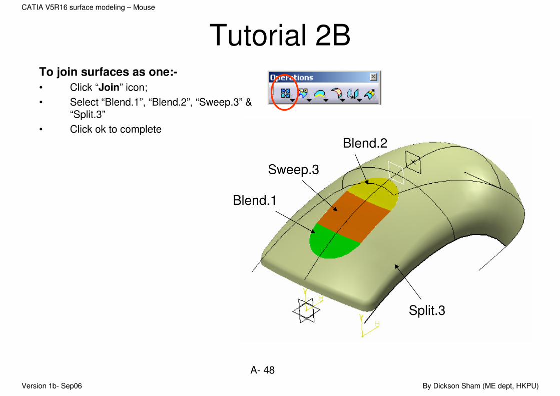
Tutorial 2BTo join surfaces as one:-
• Click “Join” icon;
• Select “Blend.1”, “Blend.2”, “Sweep.3” & “Split.3”
• Click ok to complete
Split.3
Blend.1
Sweep.3
Blend.2
Version 1b- Sep06 By Dickson Sham (ME dept, HKPU)
A- 49
CATIA V5R16 surface modeling – Mouse
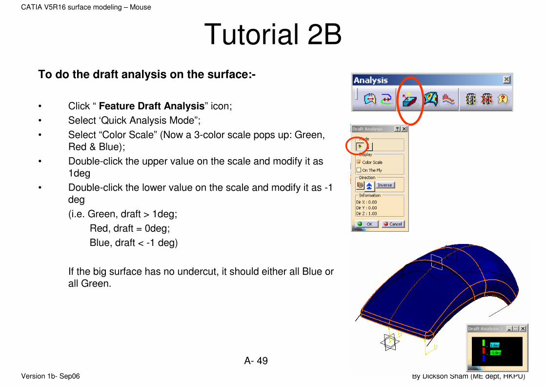
Tutorial 2BTo do the draft analysis on the surface:-
• Click “ Feature Draft Analysis” icon;
• Select ‘Quick Analysis Mode”;
• Select “Color Scale” (Now a 3-color scale pops up: Green, Red & Blue);
• Double-click the upper value on the scale and modify it as 1deg
• Double-click the lower value on the scale and modify it as -1 deg
(i.e. Green, draft > 1deg;
Red, draft = 0deg;
Blue, draft < -1 deg)
If the big surface has no undercut, it should either all Blue orall Green.
Version 1b- Sep06 By Dickson Sham (ME dept, HKPU)
A- 50
CATIA V5R16 surface modeling – Mouse
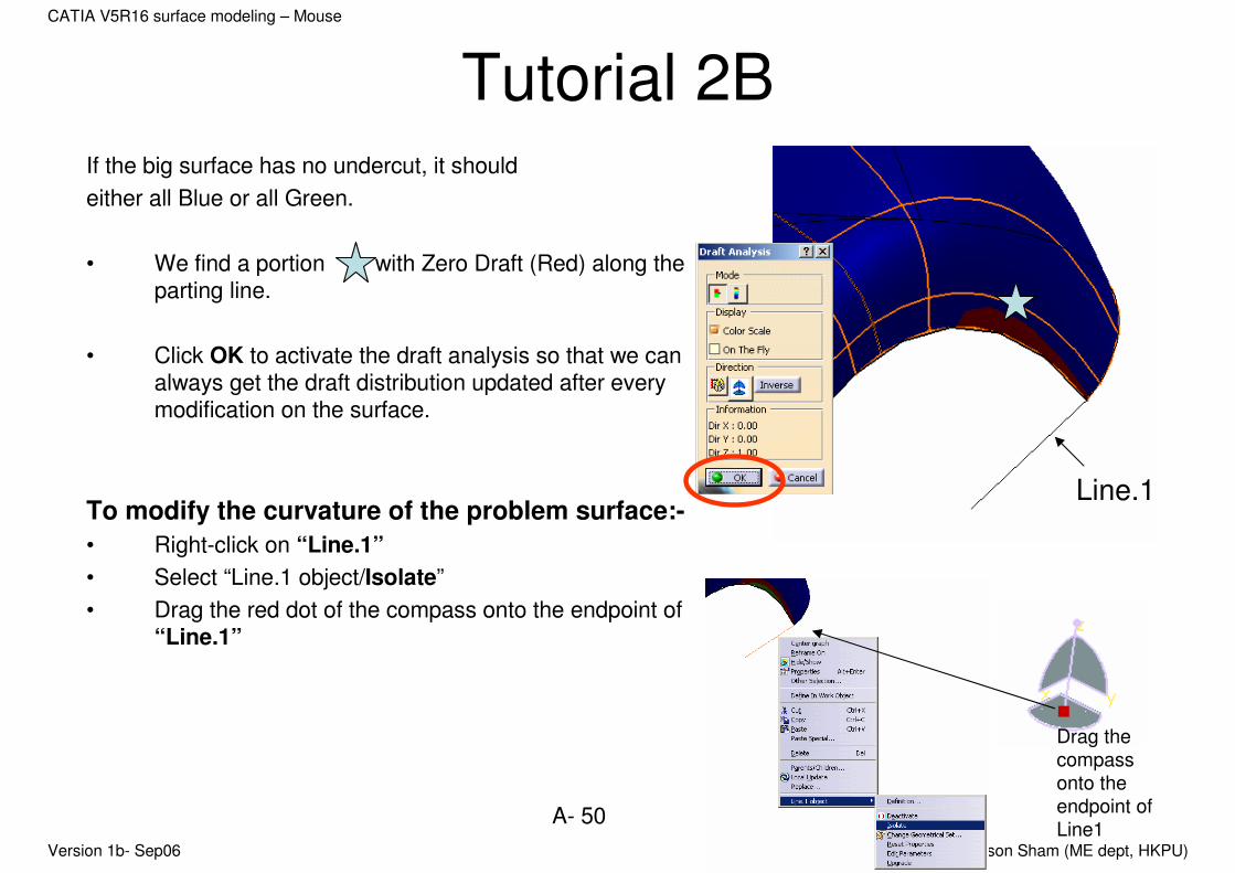
Tutorial 2BIf the big surface has no undercut, it should
either all Blue or all Green.
• We find a portion with Zero Draft (Red) along the parting line.
• Click OK to activate the draft analysis so that we can always get the draft distribution updated after every modification on the surface.
To modify the curvature of the problem surface:-
• Right-click on “Line.1”
• Select “Line.1 object/Isolate”
• Drag the red dot of the compass onto the endpoint of “Line.1”
Line.1
Drag the
compass
onto the
endpoint of
Line1
Version 1b- Sep06 By Dickson Sham (ME dept, HKPU)
A- 51
CATIA V5R16 surface modeling – Mouse
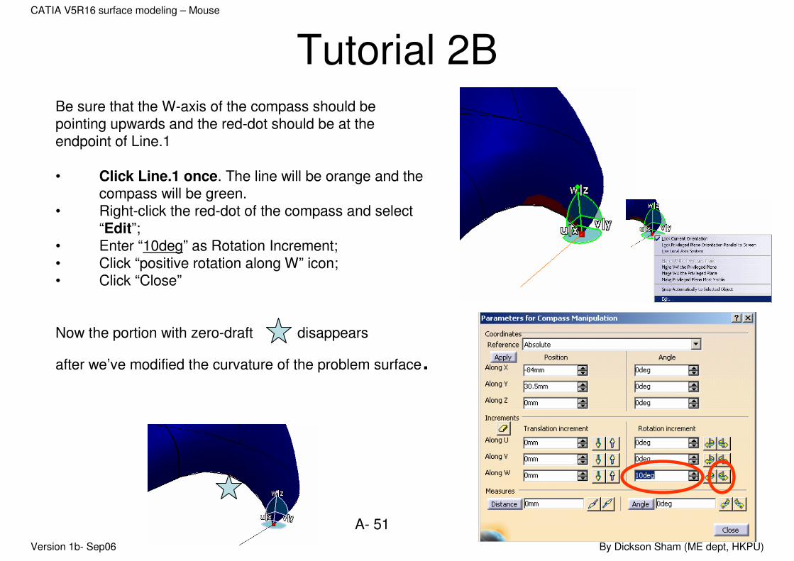
Tutorial 2BBe sure that the W-axis of the compass should be pointing upwards and the red-dot should be at the endpoint of Line.1
• Click Line.1 once. The line will be orange and the compass will be green.
• Right-click the red-dot of the compass and select “Edit”;
• Enter “10deg” as Rotation Increment;• Click “positive rotation along W” icon;• Click “Close”
Now the portion with zero-draft disappears
after we’ve modified the curvature of the problem surface.
Version 1b- Sep06 By Dickson Sham (ME dept, HKPU)
A- 52
CATIA V5R16 surface modeling – Mouse
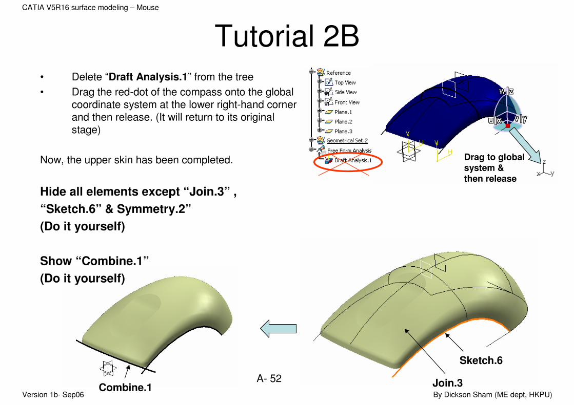
Tutorial 2B• Delete “Draft Analysis.1” from the tree
• Drag the red-dot of the compass onto the global coordinate system at the lower right-hand corner and then release. (It will return to its original stage)
Now, the upper skin has been completed.
Hide all elements except “Join.3” ,
“Sketch.6” & Symmetry.2”
(Do it yourself)
Show “Combine.1”
(Do it yourself)
Drag to global system & then release
Join.3
Sketch.6
Combine.1

Version 1b- Sep06 By Dickson Sham (ME dept, HKPU)
A- 53
CATIA V5R16 surface modeling – Mouse
Tutorial 2BWe are going to build a lower skin…
To create a swept surface:-
• Click “Sweep” icon
• Select “Line” as Profile-type
• Select “with draft direction” as Subtype
• Select “Combine.1” as Guide Curve1
• Select “xy plane” as direction
• Enter 10deg as Angle
• Select inward downward arrow
• Enter 20mm as Length1
• Click ok to complete
Version 1b- Sep06 By Dickson Sham (ME dept, HKPU)
A- 54
CATIA V5R16 surface modeling – Mouse
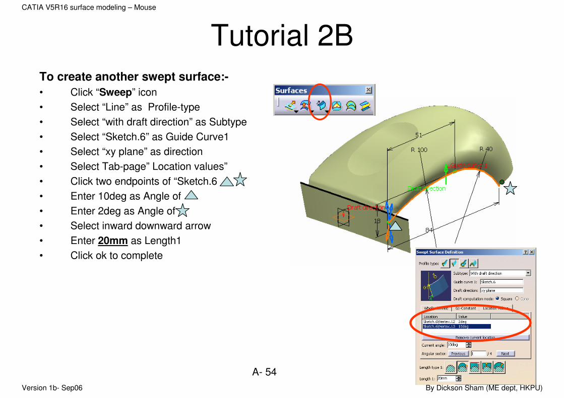
Tutorial 2BTo create another swept surface:-
• Click “Sweep” icon
• Select “Line” as Profile-type
• Select “with draft direction” as Subtype
• Select “Sketch.6” as Guide Curve1
• Select “xy plane” as direction
• Select Tab-page” Location values”
• Click two endpoints of “Sketch.6
• Enter 10deg as Angle of
• Enter 2deg as Angle of
• Select inward downward arrow
• Enter 20mm as Length1
• Click ok to complete
Version 1b- Sep06 By Dickson Sham (ME dept, HKPU)
A- 55
CATIA V5R16 surface modeling – Mouse
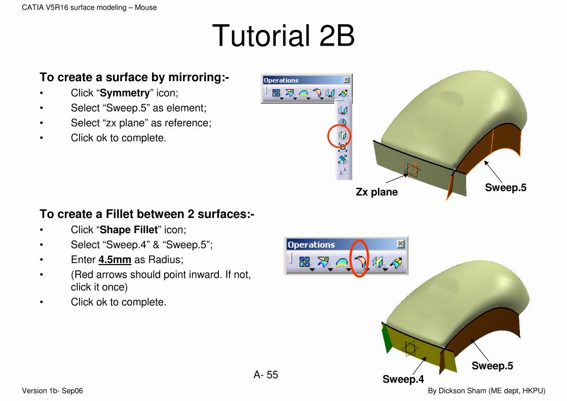
Tutorial 2BTo create a surface by mirroring:-
• Click “Symmetry” icon;
• Select “Sweep.5” as element;
• Select “zx plane” as reference;
• Click ok to complete.
To create a Fillet between 2 surfaces:-
• Click “Shape Fillet” icon;
• Select “Sweep.4” & “Sweep.5”;
• Enter 4.5mm as Radius;
• (Red arrows should point inward. If not, click it once)
• Click ok to complete.
Zx plane Sweep.5
Sweep.5
Sweep.4
Version 1b- Sep06 By Dickson Sham (ME dept, HKPU)
A- 56
CATIA V5R16 surface modeling – Mouse
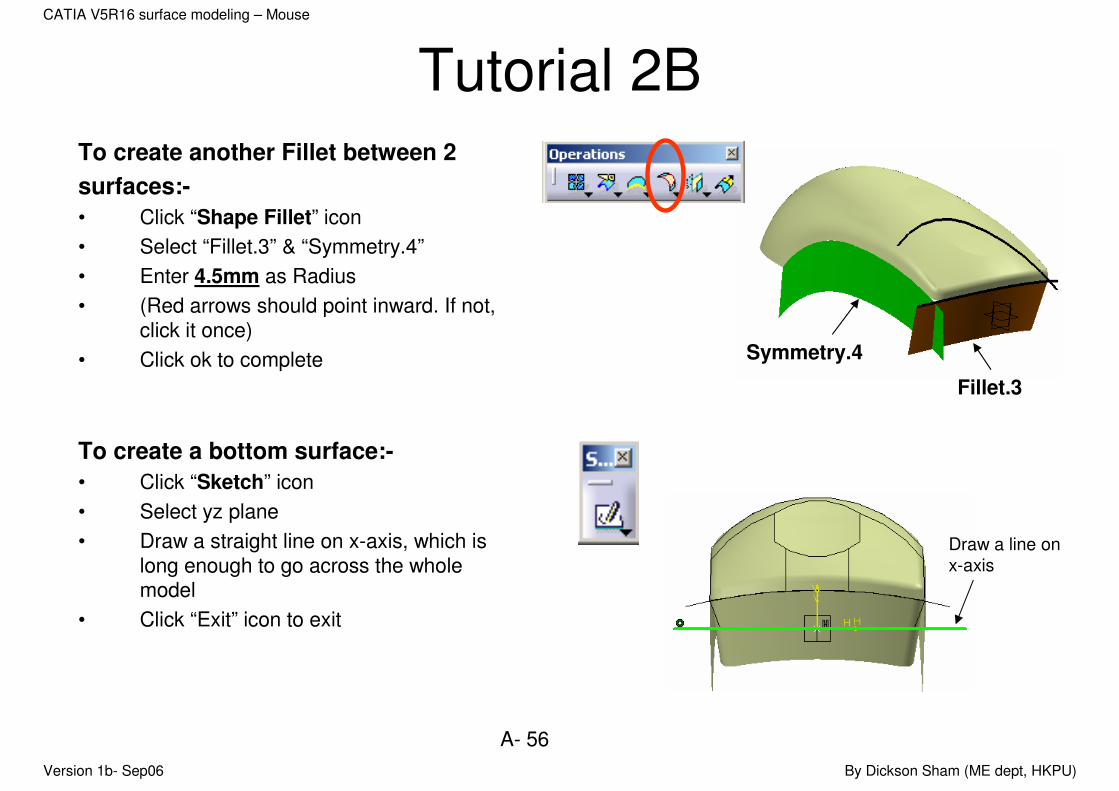
Tutorial 2BTo create another Fillet between 2
surfaces:-
• Click “Shape Fillet” icon
• Select “Fillet.3” & “Symmetry.4”
• Enter 4.5mm as Radius
• (Red arrows should point inward. If not, click it once)
• Click ok to complete
To create a bottom surface:-
• Click “Sketch” icon
• Select yz plane
• Draw a straight line on x-axis, which is long enough to go across the whole model
• Click “Exit” icon to exit
Fillet.3
Symmetry.4
Draw a line on
x-axis

Version 1b- Sep06 By Dickson Sham (ME dept, HKPU)
A- 57
CATIA V5R16 surface modeling – Mouse
Tutorial 2B• Click “Extrude” icon;
• Enter 120mm as Limit 1;
• (You may need to click “reverse direction”icon to change the extrusion direction)
• Click ok to complete.
To join surfaces:-
• Click “Join” icon
• Select ‘Join.3” & “Fillet.4”
• Enter 0.1mm as Merging direction to correct the discrepancy between two fillet surfaces
• Click “ok” icon to exit
Fillet.4
Join.3
A small gap
Version 1b- Sep06 By Dickson Sham (ME dept, HKPU)
A- 58
CATIA V5R16 surface modeling – Mouse
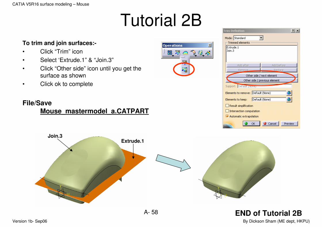
Tutorial 2BTo trim and join surfaces:-
• Click “Trim” icon
• Select ‘Extrude.1” & “Join.3”
• Click “Other side” icon until you get the surface as shown
• Click ok to complete
File/Save
Mouse_mastermodel_a.CATPART
Join.3Extrude.1
END of Tutorial 2B
Version 1b- Sep06 By Dickson Sham (ME dept, HKPU)
A- 59
CATIA V5R16 surface modeling – Mouse
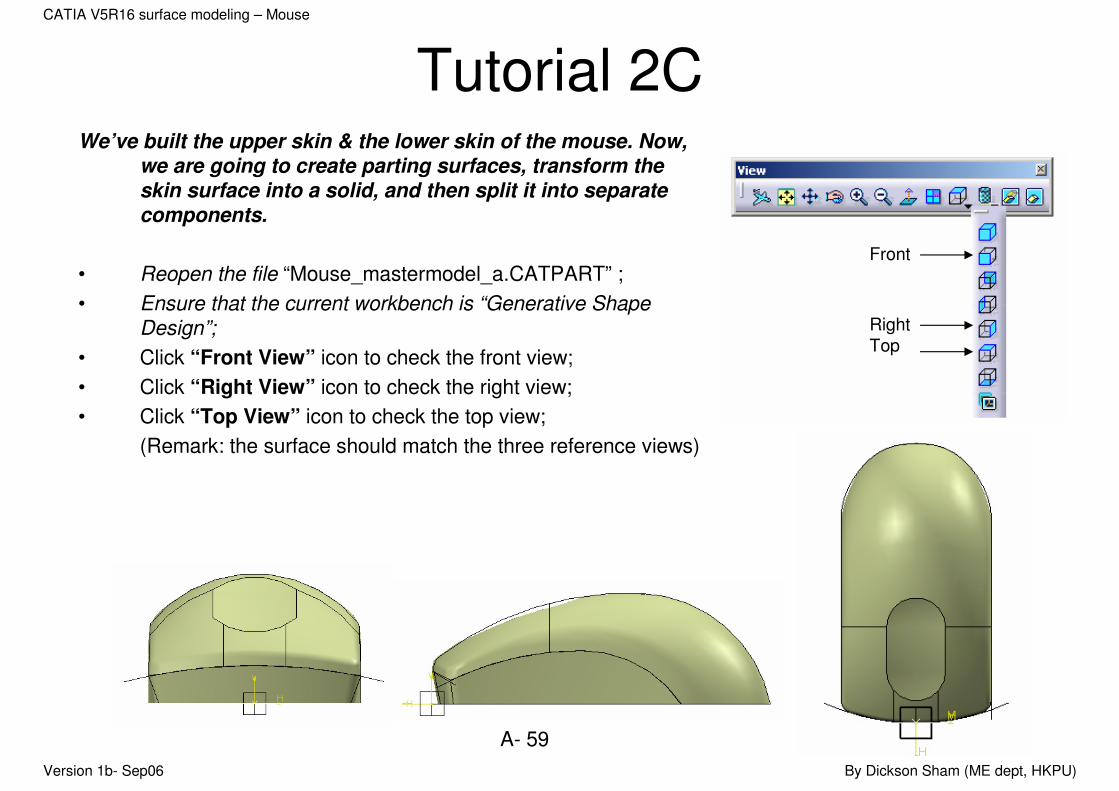
Tutorial 2CWe’ve built the upper skin & the lower skin of the mouse. Now,
we are going to create parting surfaces, transform the skin surface into a solid, and then split it into separate components.
• Reopen the file “Mouse_mastermodel_a.CATPART” ;
• Ensure that the current workbench is “Generative Shape Design”;
• Click “Front View” icon to check the front view;
• Click “Right View” icon to check the right view;
• Click “Top View” icon to check the top view;
(Remark: the surface should match the three reference views)
Front
Right
Top

Version 1b- Sep06 By Dickson Sham (ME dept, HKPU)
A- 60
CATIA V5R16 surface modeling – Mouse
Tutorial 2CTo Insert a Geometrical Set:-
• Select “Insert/Geometrical Set…” from the menu bar;
• Enter “Parting Surfaces” as Name;
• Click ok to confirm.
• (Now a new set is created. It is underlined, and so all the coming elements will be stored under this set.)
To create a swept surface:-
• Click “Sweep” icon;
• Select “Explicit” as profile type;
• Select “With reference surface” as subtype;
• Select “Combine.1” as profile;
• Select “Sketch.6” as Guide curve;
• Click ok to complete.
Version 1b- Sep06 By Dickson Sham (ME dept, HKPU)
A- 61
CATIA V5R16 surface modeling – Mouse
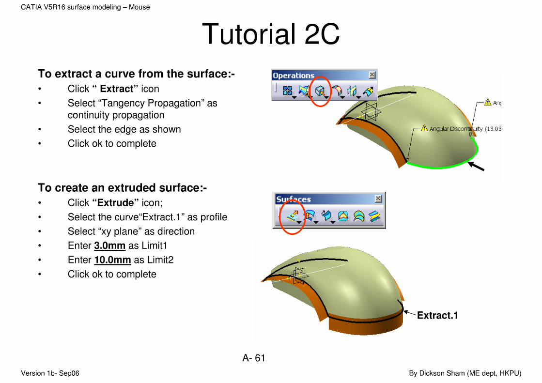
Tutorial 2CTo extract a curve from the surface:-
• Click “ Extract” icon
• Select “Tangency Propagation” as continuity propagation
• Select the edge as shown
• Click ok to complete
To create an extruded surface:-
• Click “Extrude” icon;
• Select the curve“Extract.1” as profile
• Select “xy plane” as direction
• Enter 3.0mm as Limit1
• Enter 10.0mm as Limit2
• Click ok to complete
Extract.1
Version 1b- Sep06 By Dickson Sham (ME dept, HKPU)
A- 62
CATIA V5R16 surface modeling – Mouse
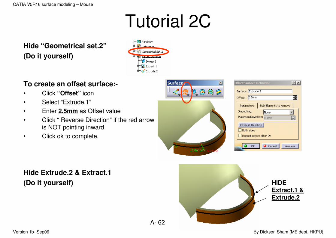
Tutorial 2CHide “Geometrical set.2”
(Do it yourself)
To create an offset surface:-
• Click “Offset” icon
• Select “Extrude.1”
• Enter 2.5mm as Offset value
• Click “ Reverse Direction” if the red arrow is NOT pointing inward
• Click ok to complete.
Hide Extrude.2 & Extract.1
(Do it yourself) HIDE Extract.1 & Extrude.2

Version 1b- Sep06 By Dickson Sham (ME dept, HKPU)
A- 63
CATIA V5R16 surface modeling – Mouse
Tutorial 2CTo extend a surface:-
• Click “ Extrapolate” icon
• Select the edge of Sweep.6 as boundary;
• Select “Sweep.6” as Extrapolated
• Enter 20mm as Length
• Select “Assemble result” option
• Click ok to complete
Similarly,
Extend the both edges of the Offset.1
by 10mm (Do it yourself)
Extended by 10mm
Offset.1

Version 1b- Sep06 By Dickson Sham (ME dept, HKPU)
A- 64
CATIA V5R16 surface modeling – Mouse
Tutorial 2CTo create a line:-
• Click “ line” icon
• Select the two end points of the surface
• Click ok to complete
To create an extruded surface:-
• Click “Extrude” icon
• Select the line Line.3 as profile
• Select yz plane as direction
• Enter 50mm as Limit1
• Enter 0 mm as Limit2
• Click “ Reverse Direction” to get the surface as shown
• Click ok to complete
Line.3
Version 1b- Sep06 By Dickson Sham (ME dept, HKPU)
A- 65
CATIA V5R16 surface modeling – Mouse
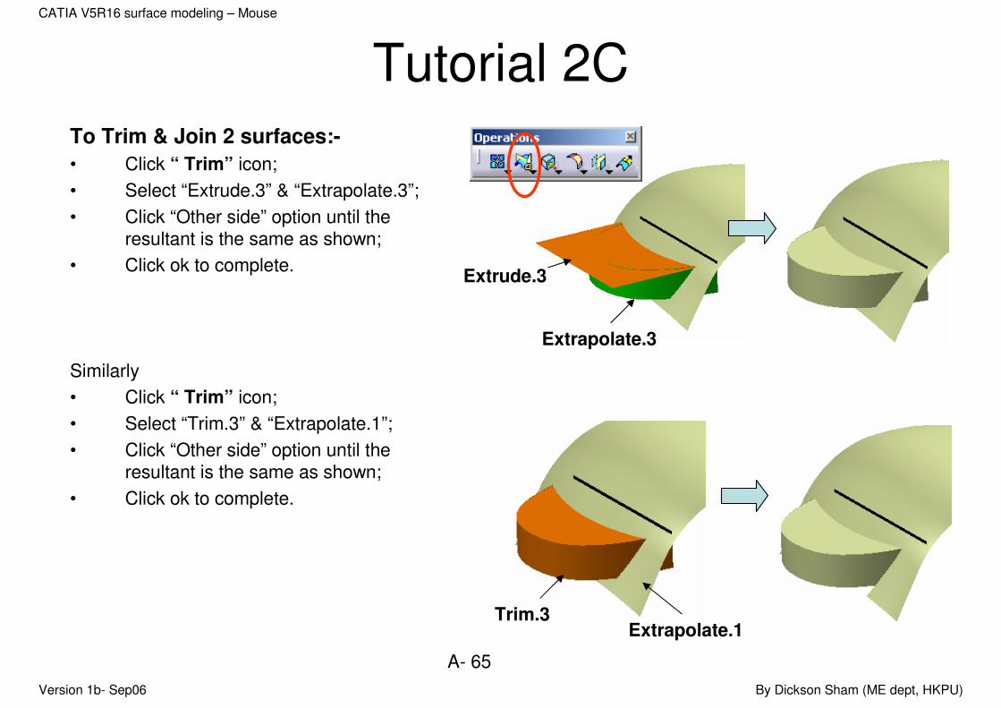
Tutorial 2CTo Trim & Join 2 surfaces:-
• Click “ Trim” icon;
• Select “Extrude.3” & “Extrapolate.3”;
• Click “Other side” option until the resultant is the same as shown;
• Click ok to complete.
Similarly
• Click “ Trim” icon;
• Select “Trim.3” & “Extrapolate.1”;
• Click “Other side” option until the resultant is the same as shown;
• Click ok to complete.
Extrapolate.3
Extrude.3
Extrapolate.1Trim.3

Version 1b- Sep06 By Dickson Sham (ME dept, HKPU)
A- 66
CATIA V5R16 surface modeling – Mouse
Tutorial 2CShow Geometrical set.2 again
(Do it yourself)
To show previous element:-
• Click “Swap visible space” icon
• Select “Sketch.9” & “Plane.4”
• Click “Hide/Show” icon (Now the two elements are moved to the visible space)
• Click “Swap visible space” icon
Plane.4
Sketch.9
Version 1b- Sep06 By Dickson Sham (ME dept, HKPU)
A- 67
CATIA V5R16 surface modeling – Mouse
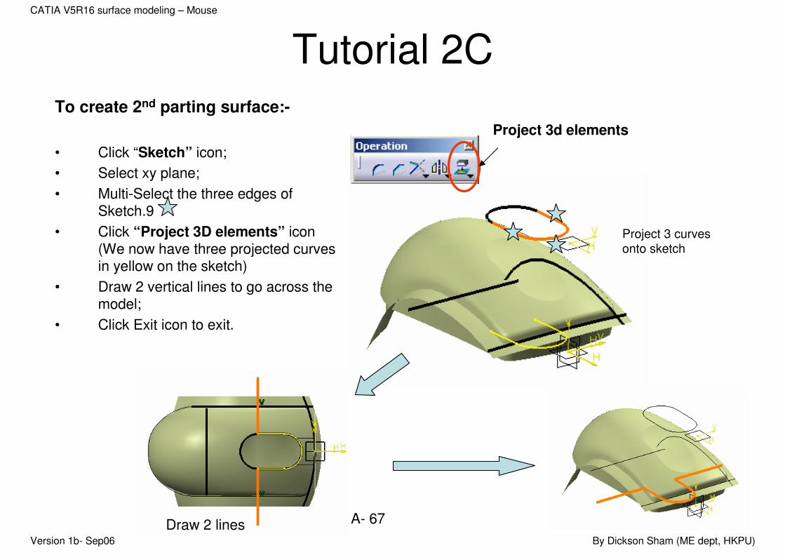
Tutorial 2CTo create 2nd parting surface:-
• Click “Sketch” icon;
• Select xy plane;
• Multi-Select the three edges of Sketch.9
• Click “Project 3D elements” icon (We now have three projected curves in yellow on the sketch)
• Draw 2 vertical lines to go across the model;
• Click Exit icon to exit.
Project 3d elements
Project 3 curves
onto sketch
Draw 2 lines

Version 1b- Sep06 By Dickson Sham (ME dept, HKPU)
A- 68
CATIA V5R16 surface modeling – Mouse
Tutorial 2C• Click “Extrude” icon;
• Select “Sketch.11” as profile;
• Select “xy plane” as direction (automatically)
• Enter 50mm as Limit1;
• Click ok to complete.
Hide all elements except
Xy plane
Yx plane
Zx plane
Trim.2 (last element under Geometrical set.2)
Trim.6 (under Parting Surfaces)
Extrude.4 (under Parting Surfaces)
(Do it yourself)
Sketch.11
Extrude.4
Trim.6
Trim.2
Version 1b- Sep06 By Dickson Sham (ME dept, HKPU)
A- 69
CATIA V5R16 surface modeling – Mouse
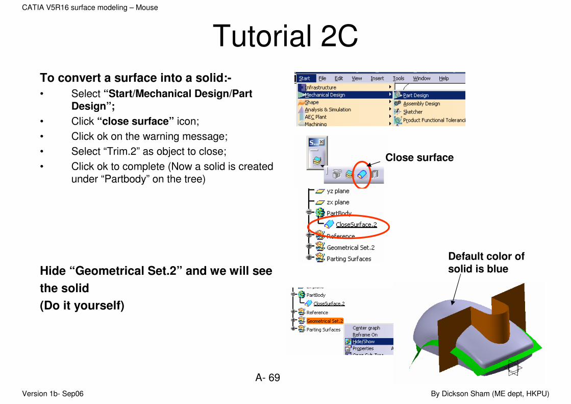
Tutorial 2CTo convert a surface into a solid:-
• Select “Start/Mechanical Design/Part Design”;
• Click “close surface” icon;
• Click ok on the warning message;
• Select “Trim.2” as object to close;
• Click ok to complete (Now a solid is created under “Partbody” on the tree)
Hide “Geometrical Set.2” and we will see
the solid
(Do it yourself)
Close surface
Default color of solid is blue
Version 1b- Sep06 By Dickson Sham (ME dept, HKPU)
A- 70
CATIA V5R16 surface modeling – Mouse
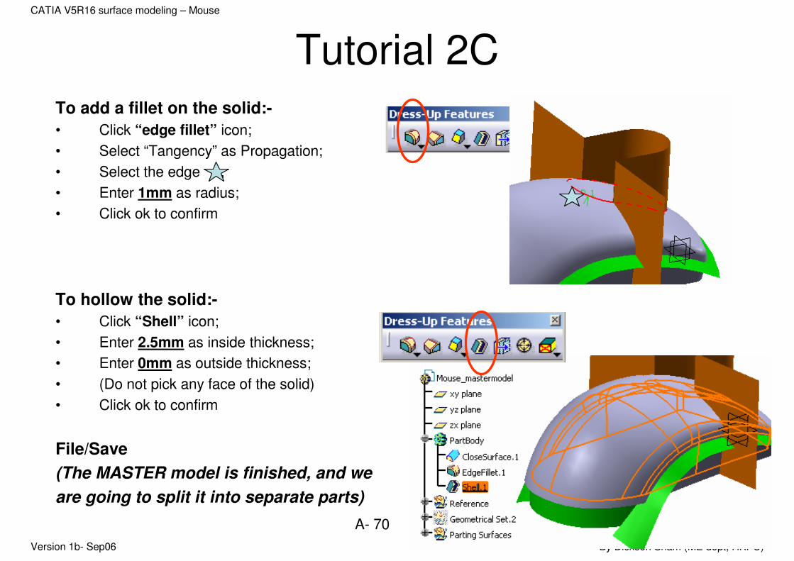
Tutorial 2CTo add a fillet on the solid:-
• Click “edge fillet” icon;
• Select “Tangency” as Propagation;
• Select the edge ;
• Enter 1mm as radius;
• Click ok to confirm
To hollow the solid:-
• Click “Shell” icon;
• Enter 2.5mm as inside thickness;
• Enter 0mm as outside thickness;
• (Do not pick any face of the solid)
• Click ok to confirm
File/Save
(The MASTER model is finished, and we
are going to split it into separate parts)

Version 1b- Sep06 By Dickson Sham (ME dept, HKPU)
A- 71
CATIA V5R16 surface modeling – Mouse
Tutorial 2CTo create the upper body:-
• Select File/New;
• Select Part as type;
• Enter Upper_body as part name;
• Click ok to complete.
• Select Window/Tile Vertically (we can see Mouse_Master & Upper Body at the same time)
• Right-click “PartBody” of Mouse_master_a.CatPart;
• and then select “Copy”;
• Right-click “Upper_body” of the tree of Upper_body and then select “Paste Special…”
• Select “As Result with link”;
• Click ok to complete.

Version 1b- Sep06 By Dickson Sham (ME dept, HKPU)
A- 72
CATIA V5R16 surface modeling – Mouse
Tutorial 2C• Multi-Select the two parting surfaces “Trim.4” &
Extrude.4”
• Right-click on either one and then select “Copy”
• Right-click “Upper_body” of the tree of Upper_body and then select “Paste Special…”
• Select “As Result with link”
• Click ok to complete
Surface.1
Surface.2
Version 1b- Sep06 By Dickson Sham (ME dept, HKPU)
A- 73
CATIA V5R16 surface modeling – Mouse
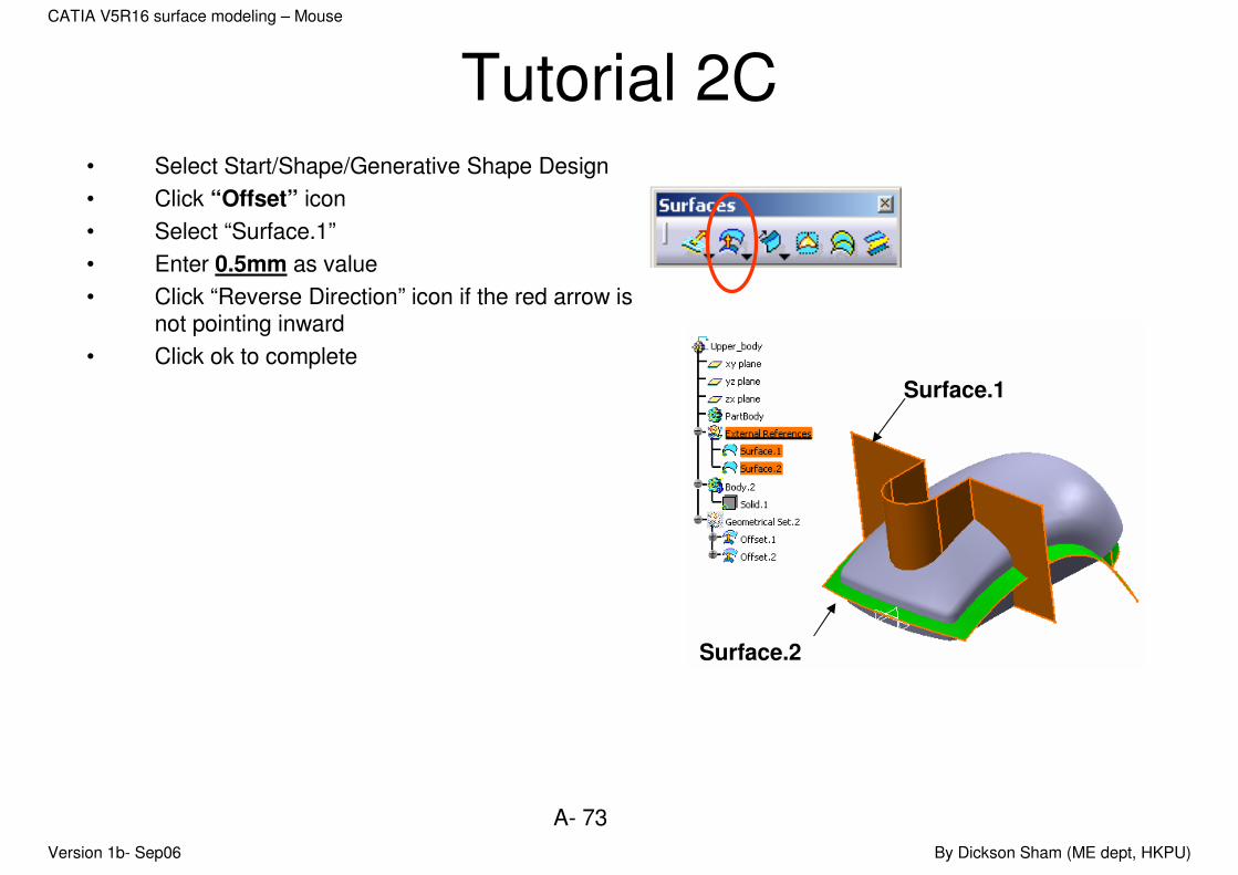
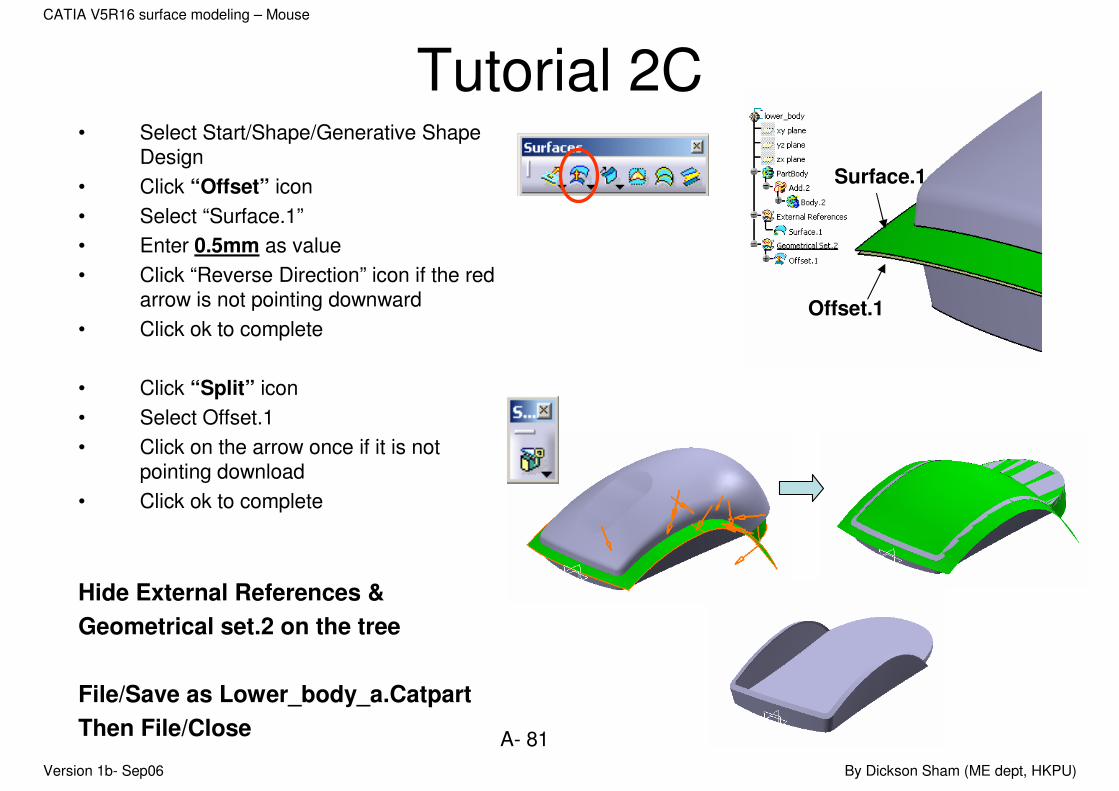
Tutorial 2C• Select Start/Shape/Generative Shape Design
• Click “Offset” icon
• Select “Surface.1”
• Enter 0.5mm as value
• Click “Reverse Direction” icon if the red arrow is not pointing inward
• Click ok to complete
Surface.1
Surface.2

Version 1b- Sep06 By Dickson Sham (ME dept, HKPU)
A- 74
CATIA V5R16 surface modeling – Mouse
Tutorial 2C• Select Start/Mechanical Design/Part
Design
• Right-Click “PartBody” and then select “Define in work object”
• Right-click “Body.2” and select “Add”
• Click “Split” icon
• Select Offset.1
• Click on the arrow once if it is not pointing inward
• Click ok to complete
The external reference solid is added into default body
Offset.1

Version 1b- Sep06 By Dickson Sham (ME dept, HKPU)
A- 75
CATIA V5R16 surface modeling – Mouse
Tutorial 2C• Click “Split” icon again
• Select Surface.2
• Click on the arrow once if it is not pointing upward
• Click ok to complete
Hide External References &
Geometrical set.2 on the tree
(Do it yourself)
Surface.2

Version 1b- Sep06 By Dickson Sham (ME dept, HKPU)
A- 76
CATIA V5R16 surface modeling – Mouse
Tutorial 2C• Select “Insert/Body” from the menu bar;
• Click “sketch” icon;
• Select xy plane;
• Draw a profile as shown;
• Click exit icon to exit.
• Click “ Pad” icon;
• Enter 50mm as First Limit;
• Enter -16.5mm as Second Limit;
• Click ok to complete.
Version 1b- Sep06 By Dickson Sham (ME dept, HKPU)
A- 77
CATIA V5R16 surface modeling – Mouse
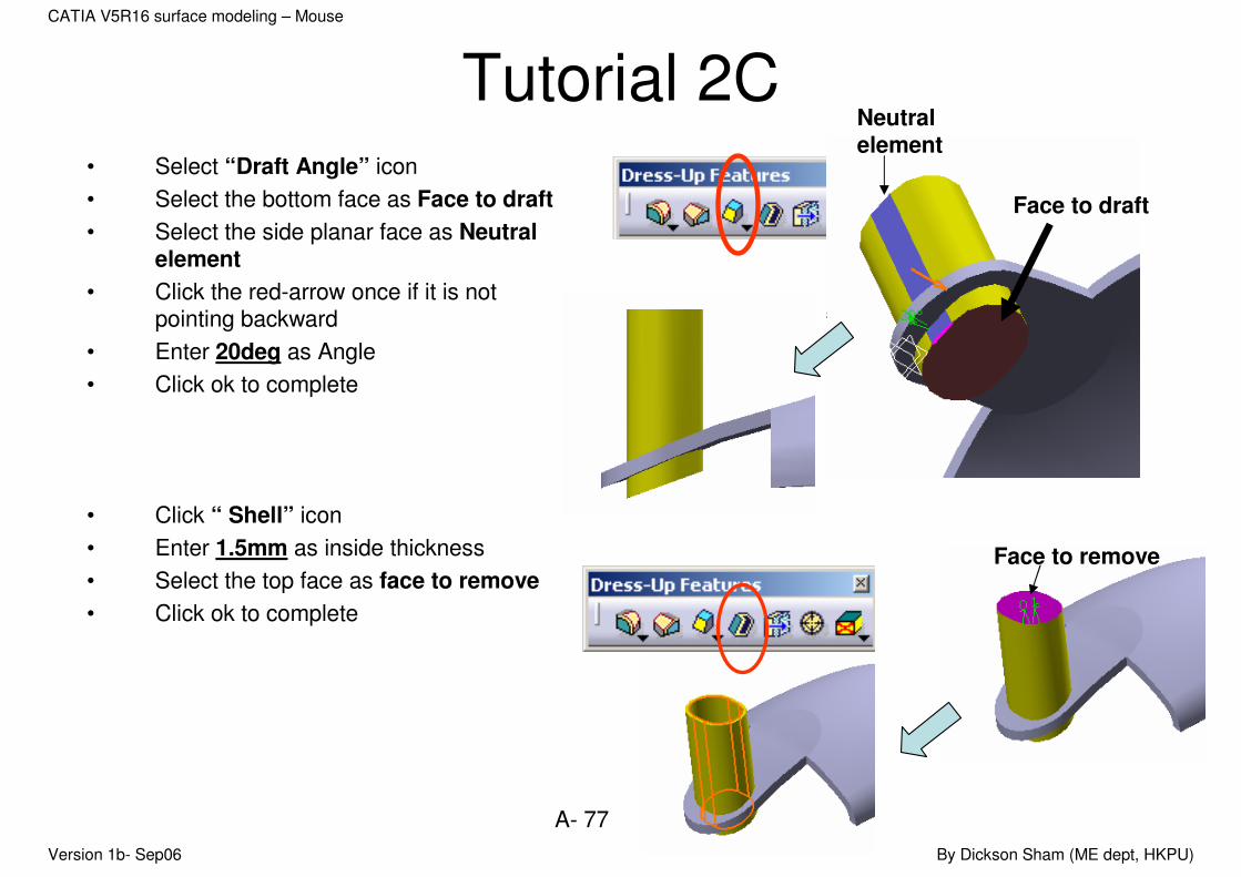
Tutorial 2C• Select “Draft Angle” icon
• Select the bottom face as Face to draft
• Select the side planar face as Neutral element
• Click the red-arrow once if it is not pointing backward
• Enter 20deg as Angle
• Click ok to complete
• Click “ Shell” icon
• Enter 1.5mm as inside thickness
• Select the top face as face to remove
• Click ok to complete
Face to draft
Neutral element
Face to remove
Version 1b- Sep06 By Dickson Sham (ME dept, HKPU)
A- 78
CATIA V5R16 surface modeling – Mouse
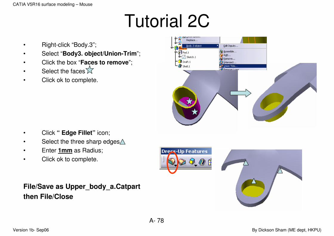
Tutorial 2C• Right-click “Body.3”;
• Select “Body3. object/Union-Trim”;
• Click the box “Faces to remove”;
• Select the faces
• Click ok to complete.
• Click “ Edge Fillet” icon;
• Select the three sharp edges
• Enter 1mm as Radius;
• Click ok to complete.
File/Save as Upper_body_a.Catpart
then File/Close
Version 1b- Sep06 By Dickson Sham (ME dept, HKPU)
A- 79
CATIA V5R16 surface modeling – Mouse
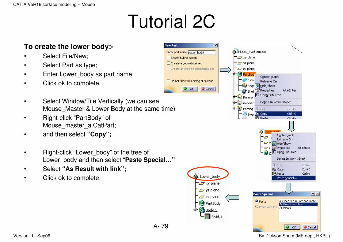
Tutorial 2CTo create the lower body:-
• Select File/New;
• Select Part as type;
• Enter Lower_body as part name;
• Click ok to complete.
• Select Window/Tile Vertically (we can see Mouse_Master & Lower Body at the same time)
• Right-click “PartBody” of Mouse_master_a.CatPart;
• and then select “Copy”;
• Right-click “Lower_body” of the tree of Lower_body and then select “Paste Special…”
• Select “As Result with link”;
• Click ok to complete.

Version 1b- Sep06 By Dickson Sham (ME dept, HKPU)
A- 80
CATIA V5R16 surface modeling – Mouse
Tutorial 2C• Select the parting surface “Trim.4””
• Right-click on either one and then select “Copy”
• Right-click “Lower_body” of the tree of Lower_body and then select “Paste Special…”
• Select “As Result with link”
• Click ok to complete
• Select Start/Mechanical Design/Part Design
• Right-Click “PartBody” and then select “define in work object”
• Right-click “Body.2” and select “Add”
Surface.1
The external reference solid is added into default body
Version 1b- Sep06 By Dickson Sham (ME dept, HKPU)
A- 81
CATIA V5R16 surface modeling – Mouse
Tutorial 2C• Select Start/Shape/Generative Shape
Design
• Click “Offset” icon
• Select “Surface.1”
• Enter 0.5mm as value
• Click “Reverse Direction” icon if the red arrow is not pointing downward
• Click ok to complete
• Click “Split” icon
• Select Offset.1
• Click on the arrow once if it is not pointing download
• Click ok to complete
Hide External References &
Geometrical set.2 on the tree
File/Save as Lower_body_a.Catpart
Then File/Close
Offset.1
Surface.1
Version 1b- Sep06 By Dickson Sham (ME dept, HKPU)
A- 82
CATIA V5R16 surface modeling – Mouse
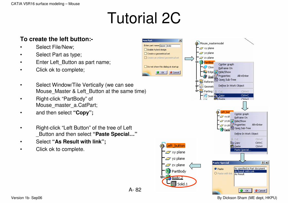
Tutorial 2CTo create the left button:-
• Select File/New;
• Select Part as type;
• Enter Left_Button as part name;
• Click ok to complete;
• Select Window/Tile Vertically (we can see Mouse_Master & Left_Button at the same time)
• Right-click “PartBody” of Mouse_master_a.CatPart;
• and then select “Copy”;
• Right-click “Left Button” of the tree of Left _Button and then select “Paste Special…”
• Select “As Result with link”;
• Click ok to complete.

Version 1b- Sep06 By Dickson Sham (ME dept, HKPU)
A- 83
CATIA V5R16 surface modeling – Mouse
Tutorial 2C• Multi-Select the two parting surfaces “Trim.4” &
Extrude.4”
• Right-click on either one and then select “Copy”
• Right-click “Left_button” of the tree of Left Button and then select “Paste Special…”
• Select “As Result with link”
• Click ok to complete
Surface.1
Surface.2
Version 1b- Sep06 By Dickson Sham (ME dept, HKPU)
A- 84
CATIA V5R16 surface modeling – Mouse
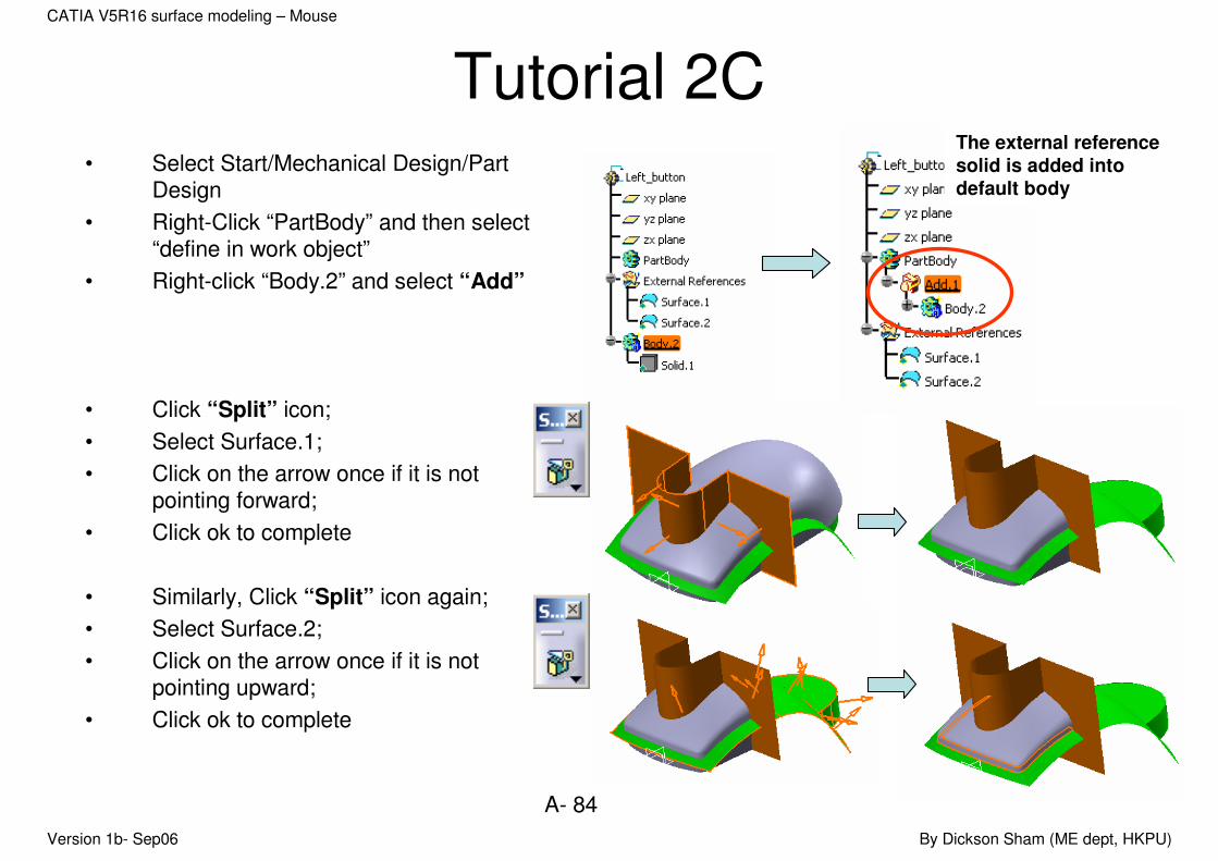
Tutorial 2C• Select Start/Mechanical Design/Part
Design
• Right-Click “PartBody” and then select “define in work object”
• Right-click “Body.2” and select “Add”
• Click “Split” icon;
• Select Surface.1;
• Click on the arrow once if it is not pointing forward;
• Click ok to complete
• Similarly, Click “Split” icon again;
• Select Surface.2;
• Click on the arrow once if it is not pointing upward;
• Click ok to complete
The external reference solid is added into default body
Version 1b- Sep06 By Dickson Sham (ME dept, HKPU)
A- 85
CATIA V5R16 surface modeling – Mouse
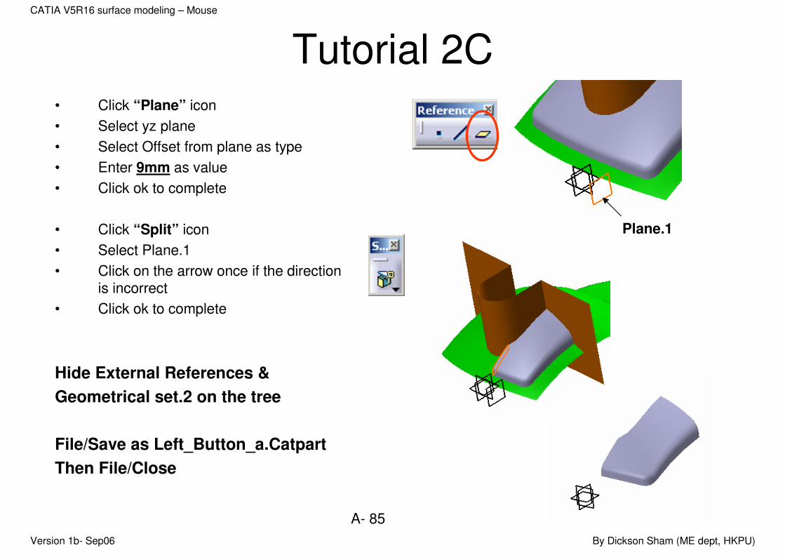
Tutorial 2C• Click “Plane” icon
• Select yz plane
• Select Offset from plane as type
• Enter 9mm as value
• Click ok to complete
• Click “Split” icon
• Select Plane.1
• Click on the arrow once if the direction is incorrect
• Click ok to complete
Hide External References &
Geometrical set.2 on the tree
File/Save as Left_Button_a.Catpart
Then File/Close
Plane.1
Version 1b- Sep06 By Dickson Sham (ME dept, HKPU)
A- 86
CATIA V5R16 surface modeling – Mouse
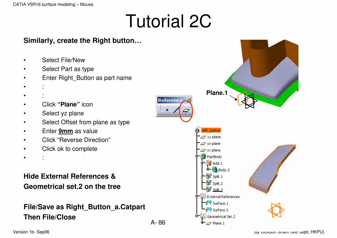
Tutorial 2CSimilarly, create the Right button…
• Select File/New
• Select Part as type
• Enter Right_Button as part name
• :
• :
• Click “Plane” icon
• Select yz plane
• Select Offset from plane as type
• Enter 9mm as value
• Click “Reverse Direction”
• Click ok to complete
• :
Hide External References &
Geometrical set.2 on the tree
File/Save as Right_Button_a.Catpart
Then File/Close
Plane.1
Version 1b- Sep06 By Dickson Sham (ME dept, HKPU)
A- 87
CATIA V5R16 surface modeling – Mouse
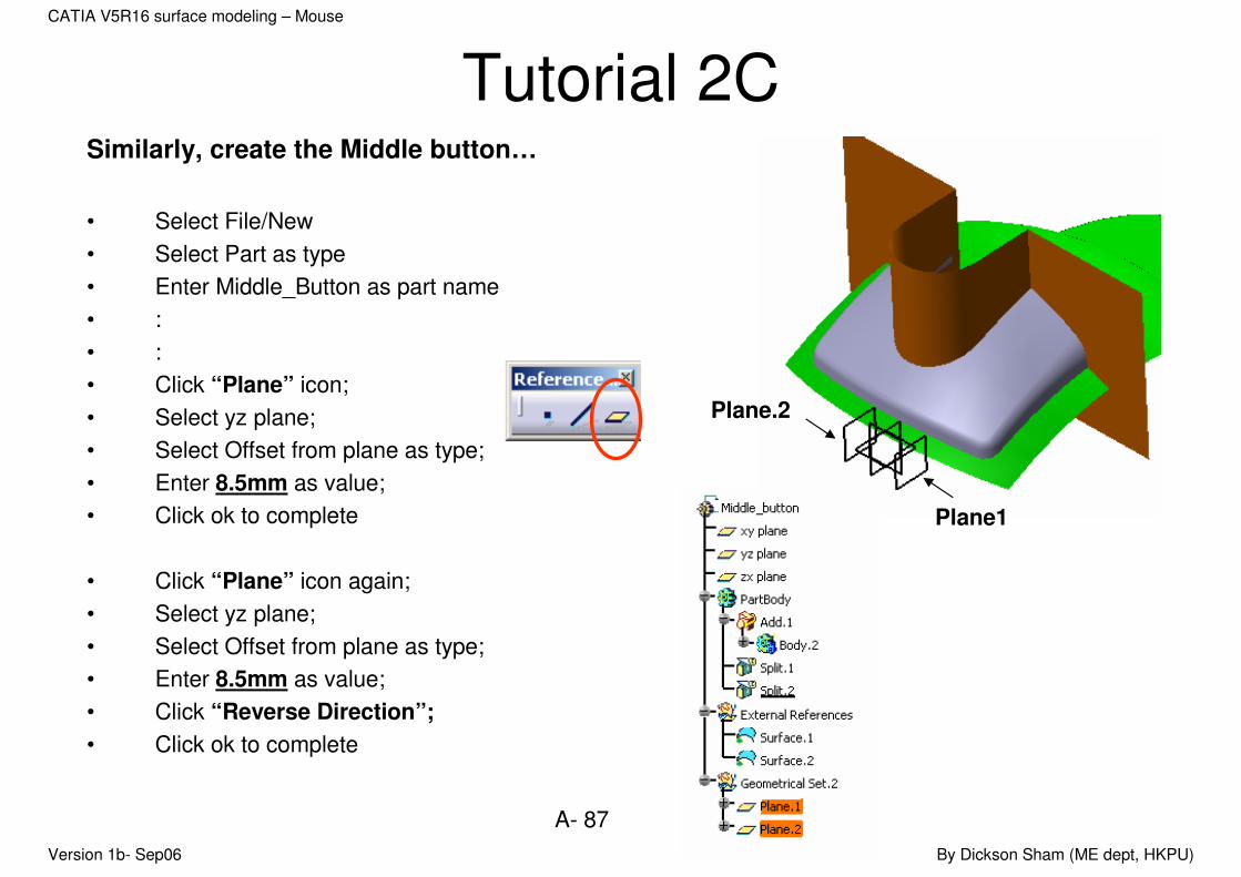
Tutorial 2CSimilarly, create the Middle button…
• Select File/New
• Select Part as type
• Enter Middle_Button as part name
• :
• :
• Click “Plane” icon;
• Select yz plane;
• Select Offset from plane as type;
• Enter 8.5mm as value;
• Click ok to complete
• Click “Plane” icon again;
• Select yz plane;
• Select Offset from plane as type;
• Enter 8.5mm as value;
• Click “Reverse Direction”;
• Click ok to complete
Plane.2
Plane1
Version 1b- Sep06 By Dickson Sham (ME dept, HKPU)
A- 88
CATIA V5R16 surface modeling – Mouse
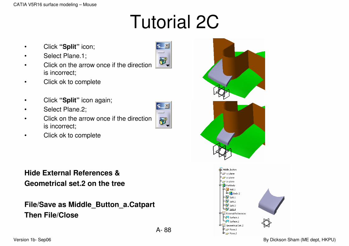
Tutorial 2C• Click “Split” icon;
• Select Plane.1;
• Click on the arrow once if the direction is incorrect;
• Click ok to complete
• Click “Split” icon again;
• Select Plane.2;
• Click on the arrow once if the direction is incorrect;
• Click ok to complete
Hide External References &
Geometrical set.2 on the tree
File/Save as Middle_Button_a.Catpart
Then File/Close

Version 1b- Sep06 By Dickson Sham (ME dept, HKPU)
A- 89
CATIA V5R16 surface modeling – Mouse
Tutorial 2CWe have split the master into separate parts.
We should always follow the rule that one file contains one part.
Now we are going to assemble the parts into a product with other components, e.g. a scroll button.
• Close all files;
• Select “Start/Mechanical Design/Assembly Design” (A new Product will then be created);
• Right-Click “Product1” on the tree;
• Select “properties” and Select the tab page “Product”;
• Enter Mouse_assm as part name;
• Click ok to confirm
Version 1b- Sep06 By Dickson Sham (ME dept, HKPU)
A- 90
CATIA V5R16 surface modeling – Mouse
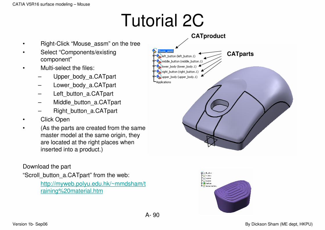
Tutorial 2C• Right-Click “Mouse_assm” on the tree
• Select “Components/existing component”
• Multi-select the files:
– Upper_body_a.CATpart
– Lower_body_a.CATpart
– Left_button_a.CATpart
– Middle_button_a.CATpart
– Right_button_a.CATpart
• Click Open
• (As the parts are created from the same master model at the same origin, they are located at the right places when inserted into a product.)
Download the part
“Scroll_button_a.CATpart” from the web:
http://myweb.polyu.edu.hk/~mmdsham/training%20material.htm
CATproduct
CATparts

Version 1b- Sep06 By Dickson Sham (ME dept, HKPU)
A- 91
CATIA V5R16 surface modeling – Mouse
Tutorial 2C• Right-Click “Mouse_assm” on the tree
• Select “Components/existing component”
• Select the files:
– Scroll_button_a.CATpart
• Drag the red dot of the compass and drop it onto the Scroll_button (The compass will turn into green and the scroll_button will be highlighted on the tree)
• Use the compass to move the Scroll button on the top of the pocket of the upper_body (Remark: the scroll button is not symmetric, the side with a hole should be closer to the center of the mouse)
A small hole
compass
Version 1b- Sep06 By Dickson Sham (ME dept, HKPU)
A- 92
CATIA V5R16 surface modeling – Mouse
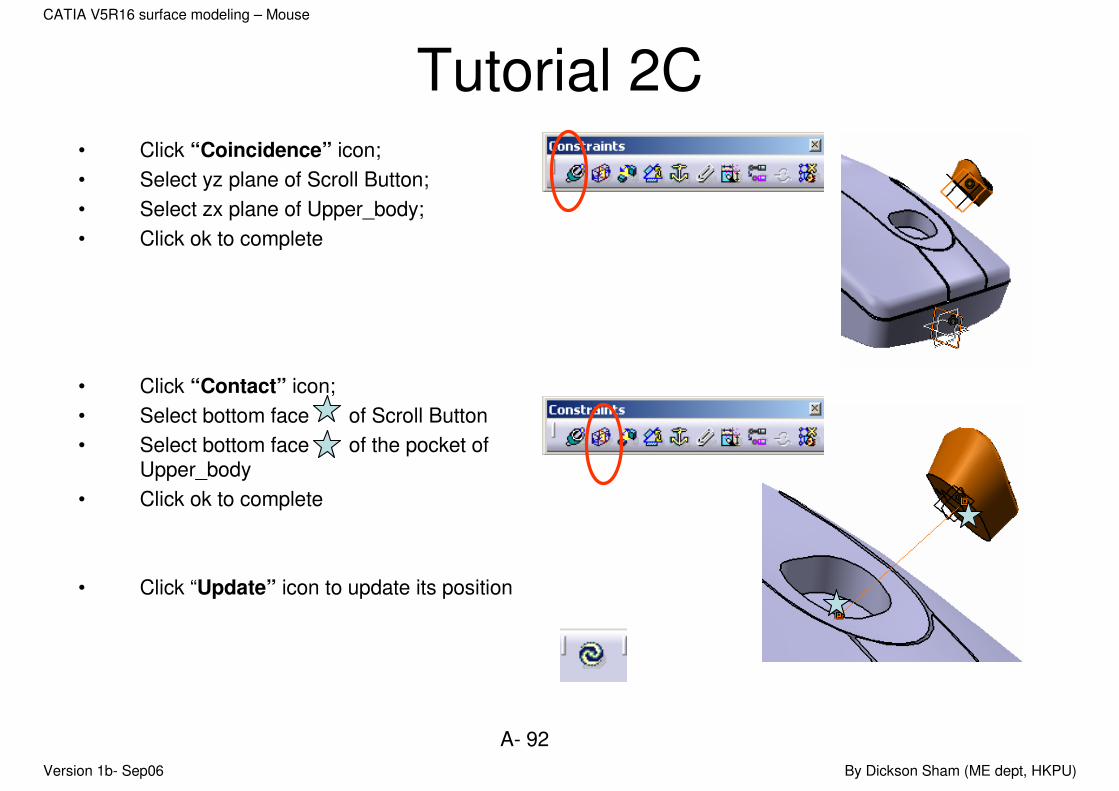
Tutorial 2C• Click “Coincidence” icon;
• Select yz plane of Scroll Button;
• Select zx plane of Upper_body;
• Click ok to complete
• Click “Contact” icon;
• Select bottom face of Scroll Button
• Select bottom face of the pocket of Upper_body
• Click ok to complete
• Click “Update” icon to update its position

Version 1b- Sep06 By Dickson Sham (ME dept, HKPU)
A- 93
CATIA V5R16 surface modeling – Mouse
Tutorial 2C• Drag the scroll_button to the center of the
pocket by using the Compass;
• Drag the red dot of the compass onto the global coordinate system at the lower righthand corner of the screen and then release;
• (Now, the compass is reset to original)
Version 1b- Sep06 By Dickson Sham (ME dept, HKPU)
A- 94
CATIA V5R16 surface modeling – Mouse
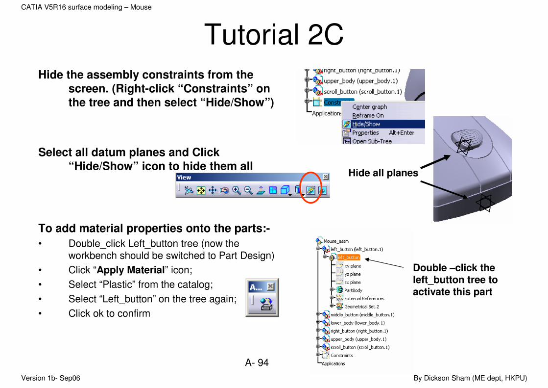
Tutorial 2CHide the assembly constraints from the
screen. (Right-click “Constraints” on
the tree and then select “Hide/Show”)
Select all datum planes and Click
“Hide/Show” icon to hide them all
To add material properties onto the parts:-
• Double_click Left_button tree (now the workbench should be switched to Part Design)
• Click “Apply Material” icon;
• Select “Plastic” from the catalog;
• Select “Left_button” on the tree again;
• Click ok to confirm
Hide all planes
Double –click the left_button tree to activate this part
Version 1b- Sep06 By Dickson Sham (ME dept, HKPU)
A- 95
CATIA V5R16 surface modeling – Mouse
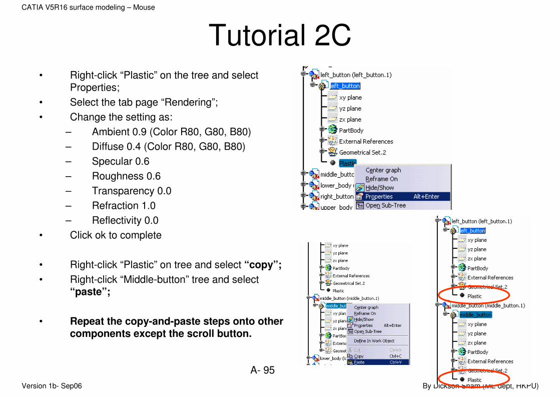
Tutorial 2C• Right-click “Plastic” on the tree and select
Properties;
• Select the tab page “Rendering”;
• Change the setting as:
– Ambient 0.9 (Color R80, G80, B80)
– Diffuse 0.4 (Color R80, G80, B80)
– Specular 0.6
– Roughness 0.6
– Transparency 0.0
– Refraction 1.0
– Reflectivity 0.0
• Click ok to complete
• Right-click “Plastic” on tree and select “copy”;
• Right-click “Middle-button” tree and select “paste”;
• Repeat the copy-and-paste steps onto other components except the scroll button.
Version 1b- Sep06 By Dickson Sham (ME dept, HKPU)
A- 96
CATIA V5R16 surface modeling – Mouse
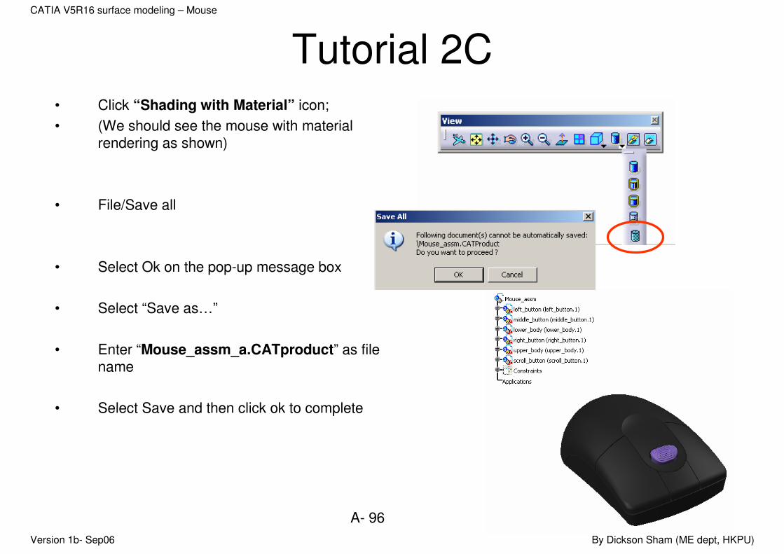
Tutorial 2C• Click “Shading with Material” icon;
• (We should see the mouse with material rendering as shown)
• File/Save all
• Select Ok on the pop-up message box
• Select “Save as…”
• Enter “Mouse_assm_a.CATproduct” as file name
• Select Save and then click ok to complete
Version 1b- Sep06 By Dickson Sham (ME dept, HKPU)
A- 97
CATIA V5R16 surface modeling – Mouse
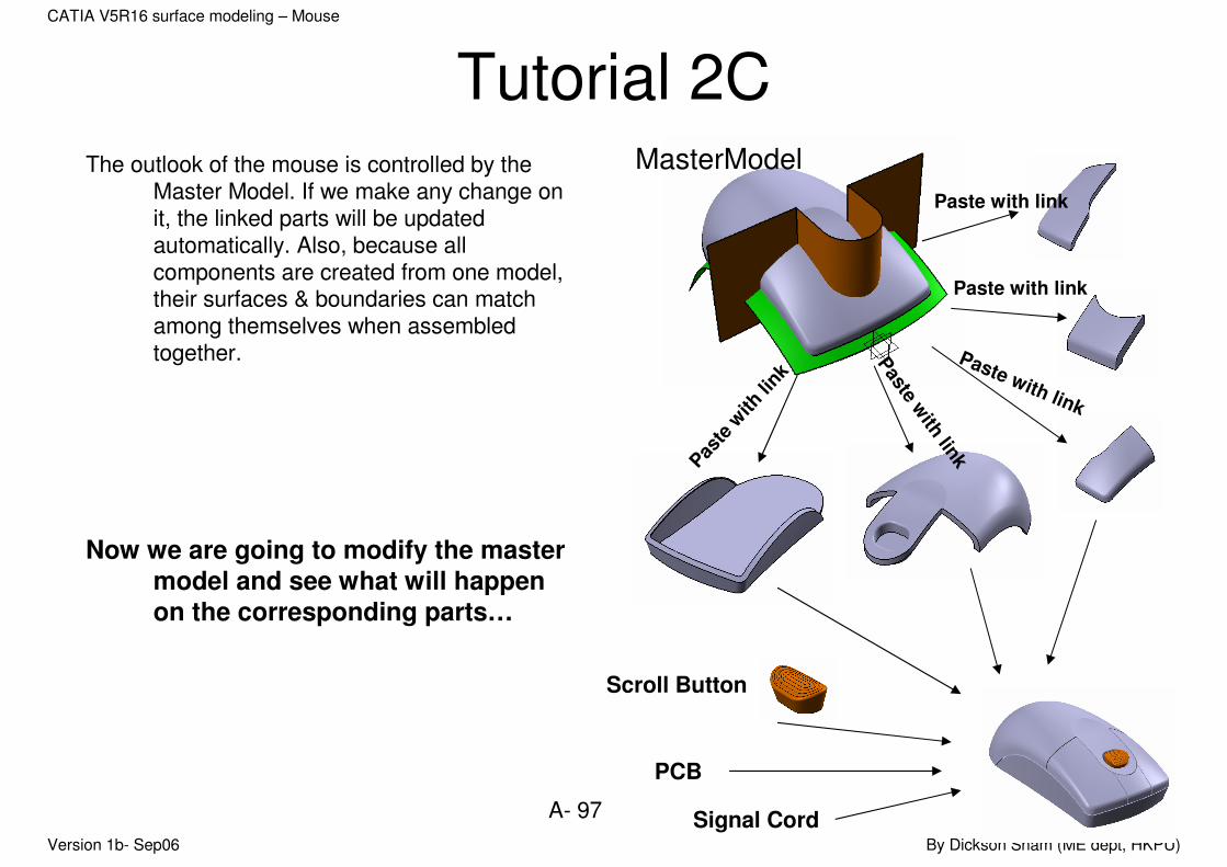
Tutorial 2CThe outlook of the mouse is controlled by the
Master Model. If we make any change on it, the linked parts will be updated automatically. Also, because all components are created from one model, their surfaces & boundaries can match among themselves when assembled together.
Now we are going to modify the master
model and see what will happen
on the corresponding parts…
MasterModel
Pas
te w
ith li
nk
Paste w
ith lin
k
Paste with link
Paste with link
Paste with link
Scroll Button
PCB
Signal Cord
Version 1b- Sep06 By Dickson Sham (ME dept, HKPU)
A- 98
CATIA V5R16 surface modeling – Mouse
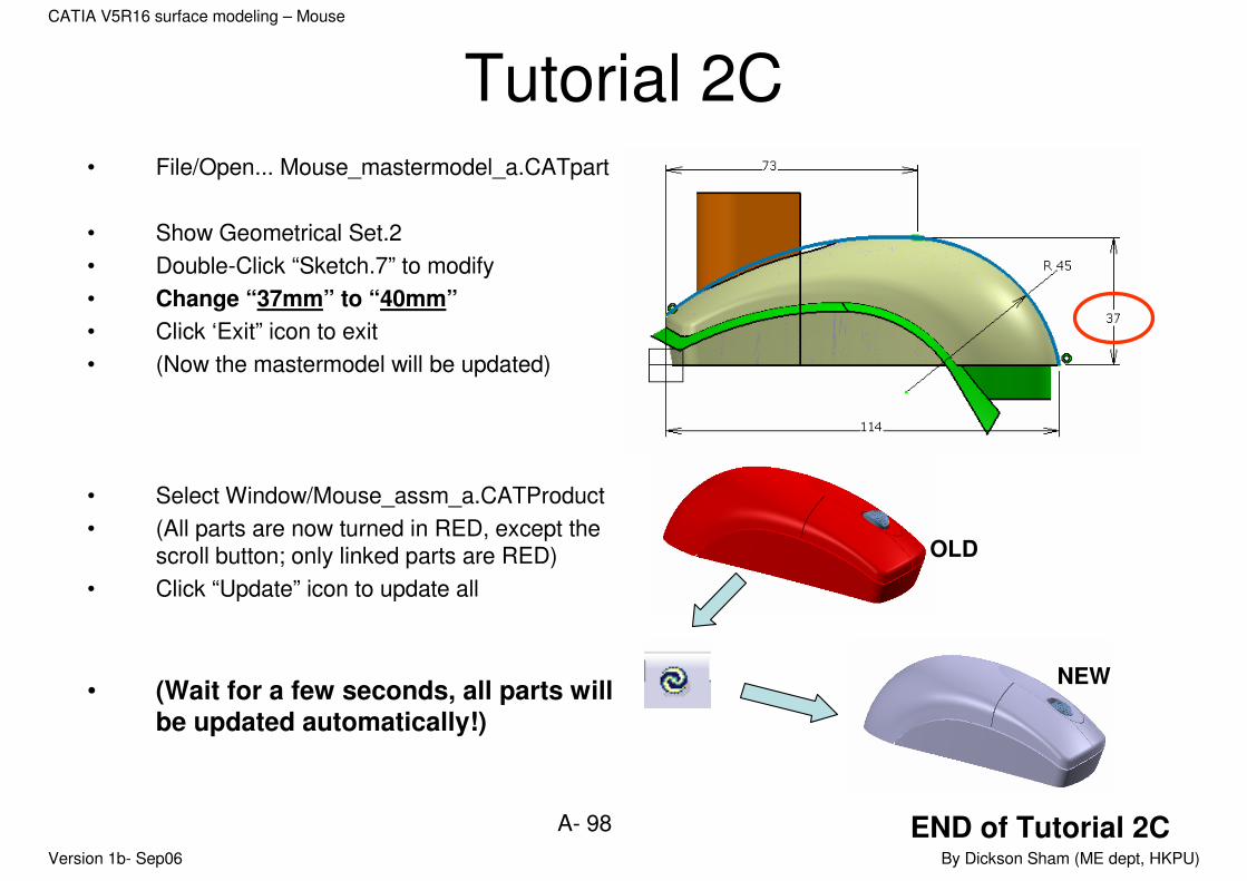
Tutorial 2C• File/Open... Mouse_mastermodel_a.CATpart
• Show Geometrical Set.2
• Double-Click “Sketch.7” to modify
• Change “37mm” to “40mm”
• Click ‘Exit” icon to exit
• (Now the mastermodel will be updated)
• Select Window/Mouse_assm_a.CATProduct
• (All parts are now turned in RED, except the scroll button; only linked parts are RED)
• Click “Update” icon to update all
• (Wait for a few seconds, all parts will be updated automatically!)
END of Tutorial 2C
OLD
NEW


