


Cisco Press800 East 96th Street
Indianapolis, IN 46240
CCNA WirelessOfficial Exam Certification Guide
Brandon James Carroll
00_1587202115_fm.qxd 9/29/08 2:42 PM Page i

CCNA Wireless Official Exam Certification GuideBrandon James Carroll
Copyright© 2009 Cisco Systems, Inc.
Published by:Cisco Press800 East 96th Street Indianapolis, IN 46240 USA
All rights reserved. No part of this book may be reproduced or transmitted in any form or by any means,electronic or mechanical, including photocopying, recording, or by any information storage and retrievalsystem, without written permission from the publisher, except for the inclusion of brief quotations in areview.
Printed in the United States of America
First Printing October 2008
Library of Congress Cataloging-in-Publication Data:
Carroll, Brandon.CCNA wireless official exam certification guide / Brandon James Carroll.
p. cm.ISBN 978-1-58720-211-7 (hbk. : CD-ROM)
1. Wireless LANs--Examinations--Study guides. 2. Electronic dataprocessing personnel--Certification--Study guides. I. Title.
TK5105.78C37 2009004.6'8076--dc22
2008038512
ISBN-13: 978-1-58720-211-7
ISBN-10: 1-58720-211-5
Warning and DisclaimerThis book is designed to provide information about the 640-721 Implementing Cisco Unified WirelessNetworking Essentials (IUWNE) certification exam. Every effort has been made to make this book ascomplete and as accurate as possible, but no warranty or fitness is implied.
The information is provided on an “as is” basis. The authors, Cisco Press, and Cisco Systems, Inc., shall haveneither liability nor responsibility to any person or entity with respect to any loss or damages arising fromthe information contained in this book or from the use of the discs or programs that may accompany it.
The opinions expressed in this book belong to the author and are not necessarily those of Cisco Systems, Inc.
Trademark AcknowledgmentsAll terms mentioned in this book that are known to be trademarks or service marks have been appropri-ately capitalized. Cisco Press or Cisco Systems, Inc., cannot attest to the accuracy of this information.Use of a term in this book should not be regarded as affecting the validity of any trademark or servicemark.
ii CCNA Wireless Official Exam Certification Guide
00_1587202115_fm.qxd 9/29/08 2:42 PM Page ii

Corporate and Government SalesThe publisher offers excellent discounts on this book when ordered in quantity for bulk purchases or spe-cial sales, which may include electronic versions and/or custom covers and content particular to your busi-ness, training goals, marketing focus, and branding interests. For more information, please contact:
U.S. Corporate and Government Sales [email protected]
For sales outside the United States please contact:International [email protected]
Feedback InformationAt Cisco Press, our goal is to create in-depth technical books of the highest quality and value. Each bookis crafted with care and precision, undergoing rigorous development that involves the unique expertise ofmembers from the professional technical community.
Readers’ feedback is a natural continuation of this process. If you have any comments regarding how wecould improve the quality of this book or otherwise alter it to better suit your needs, you can contact usthrough email at [email protected]. Please make sure to include the book title and ISBN in yourmessage.
We greatly appreciate your assistance.
Publisher: Paul Boger Associate Publisher: Dave Dusthimer
Executive Editor: Brett Bartow Cisco Representative: Anthony Wolfenden
Managing Editor: Patrick Kanouse Cisco Press Program Manager: Jeff Brady
Senior Development Editor: Christopher Cleveland Copy Editors: Karen A. Gill, Gayle Johnson
Project Editor: Mandie Frank Technical Editors: Bobby Corcoran, Robert Marg
Editorial Assistant: Vanessa Evans Proofreader: Sheri Cain, Water Crest Publishing, Inc.
Book and Cover Designer: Louisa Adair Indexer: Tim Wright
Composition: Mark Shirar
iii
Cisco has more than 200 offices worldwide. Addresses, phone numbers, and fax numbers are listed on the Cisco Website at www.cisco.com/go/offices.
CCDE, CCENT, Cisco Eos, Cisco Lumin, Cisco Nexus, Cisco StadiumVision, the Cisco logo, DCE, and Welcome to the Human Network are trademarks.; Changing the Way We Work, Live, Play, and Learn is a service mark; and Access Registrar, Aironet, AsyncOS, Bringing the Meeting To You, Catalyst, CCDA, CCDP, CCIE, CCIP, CCNA, CCNP, CCSP, CCVP, Cisco, the Cisco Certified Internetwork Expert logo, Cisco IOS, Cisco Press, Cisco Systems, Cisco Systems Capital, the Cisco Systems logo, Cisco Unity, Collaboration Without Limitation, EtherFast, EtherSwitch, Event Center, Fast Step, Follow Me Browsing, FormShare, GigaDrive, HomeLink, Internet Quotient, IOS, iPhone, iQ Expertise, the iQ logo, iQ Net Readiness Scorecard, iQuick Study, IronPort, the IronPort logo, LightStream, Linksys, MediaTone, MeetingPlace, MGX, Networkers, Networking Academy, Network Registrar, PCNow, PIX, PowerPanels, ProConnect, ScriptShare, SenderBase, SMARTnet, Spectrum Expert, StackWise, The Fastest Way to Increase Your Internet Quotient, TransPath, WebEx, and the WebEx logo are registered trademarks of Cisco Systems, Inc. and/or its affiliates in the United States and certain other countries.
All other trademarks mentioned in this document or Website are the property of their respective owners. The use of the word partner does not imply a partnership relationship between Cisco and any other company. (0805R)
Americas Headquarters Cisco Systems, Inc. San Jose, CA
Asia Pacific Headquarters Cisco Systems (USA) Pte. Ltd. Singapore
Europe Headquarters Cisco Systems International BV Amsterdam, The Netherlands
00_1587202115_fm.qxd 9/29/08 2:42 PM Page iii

About the AuthorBrandon James Carroll, CCNA, CCNP, CCSP, is one of the leading instructors forCisco security technologies in the country, teaching classes that include the CCNA,CCNP, and CCSP courses, numerous CCVP courses, and custom developed courseware.In his eight years with Ascolta, Brandon has developed and taught many private Ciscocourses for companies such as Boeing, Intel, and Cisco. He is a certified Cisco instructorand the author of Cisco Access Control Security, in addition to several Quick ReferenceSheets.
Prior to becoming a technical instructor for Ascolta, Brandon was a technician and anADSL specialist for GTE Network Services and Verizon Communications. His dutiesinvolved ISP router support and network design. As a lead engineer, he tested and main-tained Frame Relay connections between Lucent B-STDX and Cisco routers. His teamwas in charge of troubleshooting ISP Frame Relay to ATM cut-overs for ADSL customers.Brandon trained new employees at Verizon to the EPG in ADSL testing and troubleshoot-ing procedures and managed a Tekwizard database for technical information and trou-bleshooting techniques. He majored in information technology at St. Leo University.
About the Technical ReviewersBobby Corcoran, CCNA, is a systems engineer responsible for the design, configuration,implementation, and support of LAN, WAN, wireless, voice, and security infrastructuresfor a health care organization, including two acute care hospitals and several ancillaryhealth care facilities. His recent wireless experience includes the migration of a multicam-pus Cisco SWAN to CUWN architecture. Bobby holds a bachelor’s degree in businessadministration from Southern Oregon University.
Robert Marg is a wireless consulting systems engineer with Cisco. In his position atCisco, he is a technical leader in wireless and mobility and has worked closely with enter-prise, commercial, federal and transportation marketing, and product management teamsto develop and deliver solutions for numerous customers and various transportation andfederal agencies. Robert holds a bachelor’s degree in bacteriology from the University ofWisconsin-Madison.
iv CCNA Wireless Official Exam Certification Guide
00_1587202115_fm.qxd 9/29/08 2:42 PM Page iv

DedicationI would like to dedicate this book to all those engineers out there who are going to spendmany hours away from friends and family just to learn this material, advance their careers,and accelerate the network world. It’s because of you that I have done the same in writingthis book.
AcknowledgmentsI would like to thank Brett Bartow for giving me another wonderful opportunity to workon this book and to work with a handful of exceptional people.
I’d also like to thank my technical editors, Robert Marg and Bobby Corcoran, for theextremely difficult task that they underwent and for the continued support. Thanks forresponding to all my extra emails! You truly have made this a better book.
I would like to give special recognition to Christopher Cleveland, Dayna Isley, AndrewCupp, Mandie Frank, and all the good people at Cisco Press, for keeping this publicationon track.
In addition, I would like to thank Ascolta Training for giving me the opportunity toexplore areas of technology that I really love. And I want to recognize Ted Wagner andKevin Marz for their constant encouragement and support. Finally, thanks to TonyDeSimone, William Kivlen, Jack Wood, Kevin Masui, and the other instructors at Ascoltafor being there when I needed to bounce ideas off of someone.
v
00_1587202115_fm.qxd 9/29/08 2:42 PM Page v

Contents at a GlanceForeword xix
Introduction xx
Part I Wireless LAN Fundamentals 2
Chapter 1 Introduction to Wireless Networking Concepts 5
Chapter 2 Standards Bodies 21
Chapter 3 WLAN RF Principles 31
Chapter 4 WLAN Technologies and Topologies 47
Chapter 5 Antenna Communications 67
Chapter 6 Overview of the 802.11 WLAN Protocols 95
Chapter 7 Wireless Traffic Flow and AP Discovery 113
Chapter 8 Additional Wireless Technologies 131
Chapter 9 Delivering Packets from the Wireless to Wired Network 143
Part II Cisco Wireless LANs 164
Chapter 10 Cisco Wireless Networks Architecture 167
Chapter 11 Controller Discovery and Association 189
Chapter 12 Adding Mobility with Roaming 207
Chapter 13 Simple Network Configuration and Monitoring with the Cisco Controller 223
Chapter 14 Migrating Standalone APs to LWAPP 261
Chapter 15 Cisco Mobility Express 277
Chapter 16 Wireless Clients 295
Part III WLAN Maintenance and Administration 324
Chapter 17 Securing the Wireless Network 327
Chapter 18 Enterprise Wireless Management with the WCS and the Location Appliance 353
Chapter 19 Maintaining Wireless Networks 381
Chapter 20 Troubleshooting Wireless Networks 403
Part IV Final Preparation 428
Chapter 21 Final Preparation 431
Part V Appendixes 436
Appendix A Answers to the “Do I Know This Already?” Quizzes 438
Appendix B Memory Tables (on the CD only)
Appendix C Memory Tables Answer Key (on the CD only)
Glossary 450
Index 464
vi CCNA Wireless Official Exam Certification Guide
00_1587202115_fm.qxd 9/29/08 2:42 PM Page vi

ContentsForeword xix
Introduction xx
Part I Wireless LAN Fundamentals 2
Chapter 1 Introduction to Wireless Networking Concepts 5
“Do I Know This Already?” Quiz 5
Foundation Topics 8
Wireless Local-Area Networks 8
How Bandwidth Is Achieved from RF Signals 8
Unlicensed Frequency Bands Used in WLANs 9
900 MHz 11
2.4 GHz 11
5 GHz 12
Modulation Techniques and How They Work 12
DSSS 12
MIMO 16
Dynamic Rate Shifting 17
Sending Data Using CSMA/CA 17
Exam Preparation Tasks 18
Review All Key Concepts 18
Complete the Tables and Lists from Memory 18
Definition of Key Terms 18
Chapter 2 Standards Bodies 21
“Do I Know This Already?” Quiz 21
Foundation Topics 24
Wireless Standards and Regulatory Committees 24
FCC 24
ETSI 25
IEEE 27
Wi-Fi Certification 27
Exam Preparation Tasks 28
Review All the Key Topics 28
Complete the Tables and Lists from Memory 28
Definition of Key Terms 28
vii
00_1587202115_fm.qxd 9/29/08 2:42 PM Page vii

Chapter 3 WLAN RF Principles 31
“Do I Know This Already?” Quiz 31
Foundation Topics 34
Characteristics of Wireless Networks 34
Review of Wavelength 34
Review of Frequency 34
Review of Amplitude 35
What Is Effective Isotropic Radiated Power? 35
Influences on Wireless Transmissions 35
Understanding the Free Path Loss Model 35
Understanding Absorption 36
Understanding Reflection 38
Understanding Multipath 39
Understanding Scattering 39
Understanding Refraction 40
Understanding Line of Sight 41
Determining Signal Strength Influences 42
The Fresnel Zone 42
Received Signal Strength Indicator 42
Signal-to-Noise Ratio 43
Link Budget 44
Exam Preparation Tasks 45
Review All Key Concepts 45
Definition of Key Terms 45
Chapter 4 WLAN Technologies and Topologies 47
“Do I Know This Already?” Quiz 47
Foundation Topics 52
General Wireless Topologies 52
WPAN 52
WLAN 53
WMAN 54
WWAN 54
Original 802.11 Topologies 55
Overview of Ad Hoc Networks 55
Network Infrastructure Mode 55
Service Set Identifiers 58
Vendor-Specific Topology Extensions 59
Workgroup Bridges 59
Repeaters 60
viii CCNA Wireless Official Exam Certification Guide
00_1587202115_fm.qxd 9/29/08 2:42 PM Page viii

Outdoor Wireless Bridges 61
Outdoor Mesh Networks 62
Exam Preparation Tasks 64
Review All the Key Topics 64
Definition of Key Terms 64
Chapter 5 Antenna Communications 67
“Do I Know This Already?” Quiz 67
Foundation Topics 71
Principles of Antennas 71
Polarization 71
Diversity 71
Common Antenna Types 73
Omnidirectional Antennas 73
Directional Antennas 79
Antenna Connectors and Hardware 89
Attenuators 89
Amplifiers 89
Lightning Arrestors 89
Splitters 90
Exam Preparation Tasks 91
Review All the Key Topics 91
Complete the Tables and Lists from Memory 91
Definition of Key Terms 91
References in This Chapter 92
Chapter 6 Overview of the 802.11 WLAN Protocols 95
“Do I Know This Already?” Quiz 95
Foundation Topics 100
The 802.11 Protocol Family Overview 100
The Original 802.11 Protocol 100
The 802.11b Protocol 100
The 802.11g Protocol 101
How 802.11g Interacts with 802.11b 102
The 802.11a Protocol 106
802.11a Power Requirements 107
The 802.11n Protocol 108
Sending Frames 109
Antenna Considerations 109
ix
00_1587202115_fm.qxd 9/29/08 2:42 PM Page ix

Exam Preparation Tasks 110
Review All Key Concepts 110
Complete the Tables and Lists from Memory 110
Definition of Key Terms 110
End Notes 110
Chapter 7 Wireless Traffic Flow and AP Discovery 113
“Do I Know This Already?” Quiz 113
Foundation Topics 116
Wireless Frame Transmission 116
Wireless Frame Types 116
Sending a Frame 116
Wireless Frame Headers 118
Frame Types 120
Management Frames 121
Control Frames 123
Power Save Mode and Frame Types 124
Frame Speeds 125
A Wireless Connection 125
Exam Preparation Tasks 129
Review All the Key Concepts 129
Complete the Tables and Lists from Memory 129
Definition of Key Terms 129
Chapter 8 Additional Wireless Technologies 131
“Do I Know This Already?” Quiz 131
Foundation Topics 134
Cordless Phones 134
Bluetooth 135
ZigBee 135
WiMax 138
Other Types of Interference 140
Exam Preparation Tasks 141
Review All the Key Topics 141
Definition of Key Terms 141
Endnotes 141
References in This Chapter 141
Chapter 9 Delivering Packets from the Wireless to Wired Network 143
“Do I Know This Already?” Quiz 143
Foundation Topics 147
The Wireless Network Road Trip 147
x CCNA Wireless Official Exam Certification Guide
00_1587202115_fm.qxd 9/29/08 2:42 PM Page x

The Association Process 147
Sending to a Host on Another Subnet 148
Using VLANs to Add Control 153
VLAN Membership Modes 154
Configuring VLANs and Trunks 155
Creating VLANs 156
Assigning Ports to a VLAN 158
Creating Trunk Ports 159
Exam Preparation Tasks 162
Review All the Key Topics 162
Complete the Tables and Lists from Memory 162
Definition of Key Terms 163
Command References to Check Your Memory 163
End Notes 163
Part II Cisco Wireless LANs 164
Chapter 10 Cisco Wireless Networks Architecture 167
“Do I Know This Already?” Quiz 167
Foundation Topics 171
The Need for Centralized Control 171
The Cisco Solution 171
APs in the CUWN 172
WLCs in the CUWN 172
Features of the Cisco Controllers 172
Supporting Multiple Networks 173
The CUWN Architecture 174
Client Devices 176
Access Points 176
The 1130AG 177
The 1240AG 178
The 1250 Series AP 178
The 1300 Series AP/Bridge 179
The 1400 Series Wireless Bridge 180
Cisco Access Point Summary 180
Wireless LAN Controllers 181
The Cisco 44xx Series WLC 182
The 3750-G WLC 182
The Cisco WiSM 183
xi
00_1587202115_fm.qxd 9/29/08 2:42 PM Page xi

The Cisco 2106 WLC 183
The Cisco WLCM 184
Wireless LAN Controller Summary 185
Wireless Network Management 185
Exam Preparation Tasks 187
Review All the Key Topics 187
Complete the Tables and Lists from Memory 187
Definition of Key Terms 187
References 187
Chapter 11 Controller Discovery and Association 189
“Do I Know This Already?” Quiz 189
Foundation Topics 192
Understanding the Different LWAPP Modes 192
LWAPP Layer 2 Transport Mode 193
LWAPP Layer 3 Transport Mode 194
How an LWAPP AP Discovers a Controller 196
How an LWAPP AP Chooses a Controller and Joins It 197
How an LWAPP AP Receives Its Configuration 200
Redundancy for APs and Controllers 201
The AP Is Joined, Now What? 202
Local Mode 203
Monitor Mode 203
Sniffer Mode 203
Rogue Detection Mode 203
H-REAP Mode 204
Bridge Mode 204
Exam Preparation Tasks 205
Review All the Key Topics 205
Definition of Key Terms 205
Chapter 12 Adding Mobility with Roaming 207
“Do I Know This Already?” Quiz 207
Foundation Topics 210
Understanding Roaming 210
Understanding Mobility Groups 210
Types of Roaming 212
The Layer 2 Roaming Process 215
The Layer 3 Roaming Process 216
xii CCNA Wireless Official Exam Certification Guide
00_1587202115_fm.qxd 9/29/08 2:42 PM Page xii

Exam Preparation Tasks 221
Review All the Key Topics 221
Definition of Key Terms 221
Chapter 13 Simple Network Configuration and Monitoring with the CiscoController 223
“Do I Know This Already?” Quiz 223
Foundation Topics 228
Controller Terminology 228
Dynamic Interfaces 228
Static Interfaces 229
Connecting to the Controller 230
Controller Boot Sequence 230
Performing Initial CLI Configurations 232
Performing Initial Web Configurations 235
Navigating the Web Interface of the Controller 235
Configuring the Controller Using the Web Interface 238
Building the Controller Interface 238
Creating the WLAN and Tying It to the Interface 240
Modifying the Security Settings 242
Naming Access Points 243
Restricting Access to Access Points 245
Summary of Controller Configuration Using the Web Interface 247
Monitoring with the Controller 247
General Monitoring 248
Managing Rogue APs 253
Managing Clients 256
Using Internal DHCP 257
Exam Preparation Tasks 259
Review All the Key Topics 259
Definition of Key Terms 259
Chapter 14 Migrating Standalone APs to LWAPP 261
“Do I Know This Already?” Quiz 261
Foundation Topics 264
Connecting to a Standalone AP 264
Accessing the AP in Autonomous Mode 264
Using the Express Setup and Express Security for Basic Configuration 265
Working with the Web Interface 267
xiii
00_1587202115_fm.qxd 9/29/08 2:42 PM Page xiii

Converting to LWAPP 269
Converting to LWAPP Using the IOS-to-LWAPP Conversion Utility 269
Exam Preparation Tasks 275
Review All the Key Topics 275
Definition of Key Terms 275
Chapter 15 Cisco Mobility Express 277
“Do I Know This Already?” Quiz 277
Foundation Topics 280
Overview of the Small Business Communication System 280
521 AP 281
526 Wireless Express Controller 281
Comparing the Cisco Mobility Express Architecture to the CUWN
282
Configuring the 521 AP and 526 Controller 282
Using the CLI to Configure the Controller 282
Using the Web Browser to Configure the Controller 287
Using the Cisco Configuration Assistant 288
Exam Preparation Tasks 292
Review All the Key Topics 292
Definition of Key Terms 292
References 292
Chapter 16 Wireless Clients 295
“Do I Know This Already?” Quiz 295
Foundation Topics 298
Using Windows to Connect to a Wireless LAN 298
Configuring a Profile 298
How the WZC Tool Works 300
Using a Mac to Connect to a Wireless LAN 301
Configuring a Profile 301
How the AirPort Extreme Tool Works 302
Using Linux to Connect to a Wireless LAN 304
Configuring a Profile 305
How the NetworkManager Tool Works 306
Using the ADU to Connect to a Wireless LAN 307
Cisco Wireless LAN Adapters 307
Installing the ADU 308
Configuring a Profile 310
xiv CCNA Wireless Official Exam Certification Guide
00_1587202115_fm.qxd 9/29/08 2:42 PM Page xiv

Connecting to Preferred Networks 311
Manually Creating a Profile 312
Managing Profiles 315
Using Diagnostic Tools 315
The ACAU 319
The Cisco Secure Services Client 320
Licensing 320
Installation 321
Configuring Profiles 321
SSC Groups 322
SSCAU Overview 322
The Cisco Client Extension Program 322
Exam Preparation Tasks 323
Review All the Key Topics 323
Complete the Tables and Lists from Memeory 323
Definition of Key Terms 323
Part III WLAN Maintenance and Administration 324
Chapter 17 Securing the Wireless Network 327
“Do I Know This Already?” Quiz 327
Foundation Topics 331
Threats to Wireless Networks 331
Ad Hoc Networks 331
Rogue APs 331
Client Misassociation 331
Management Frame Protection 332
Wireless Attacks 332
Simple Authentications 334
Open Authentication 334
Preshared Key Authentication with Wired Equivalent Privacy 334
MAC Address Filtering 336
Centralized Authentication 336
802.1x and How It Is Used 338
The EAP Process 340
The Authentication Server 340
EAP-TLS 342
EAP-FAST 343
PEAP 344
xv
00_1587202115_fm.qxd 9/29/08 2:42 PM Page xv

LEAP 345
Authentication and Encryption 345
WPA Overview 346
WPA2 Overview 347
Exam Preparation Tasks 350
Review All the Key Topics 350
Complete the Tables and Lists from Memeory 350
Definition of Key Terms 351
References 351
Chapter 18 Enterprise Wireless Management with the WCS and the LocationAppliance 353
“Do I Know This Already?” Quiz 353
Foundation Topics 358
Introduction to the WCS 358
Installing and Configuring the WCS 358
Administration Options in the WCS 360
Adding Controllers to the WCS 362
Working with Templates 364
Auto Provisioning 367
Maps and APs in the WCS 368
Planning Mode 372
Monitoring with the WCS 376
Exam Preparation Tasks 378
Review All the Key Topics 378
Complete the Tables and Lists from Memeory 378
Definition of Key Terms 379
References 379
Chapter 19 Maintaining Wireless Networks 381
“Do I Know This Already?” Quiz 381
Foundation Topics 386
Upgrading a Controller 386
Controller Upgrade Approaches 388
Upgrade Using WCS 390
Upgrading an AP 391
Upgrading WCS 392
Managing Configurations 392
Working with AP Configuration Files 398
Resetting the Controller to the Defaults 398
xvi CCNA Wireless Official Exam Certification Guide
00_1587202115_fm.qxd 9/29/08 2:42 PM Page xvi

Exam Preparation Tasks 400
Review All the Key Topics 400
Definition of Key Terms 400
References 400
Chapter 20 Troubleshooting Wireless Networks 403
“Do I Know This Already?” Quiz 403
Foundation Topics 408
Physical Connections and LEDs 408
Common Client-Side Issues 408
Using the CLI to Troubleshoot 410
Using the Controller Interface 417
Using the Controller Logs 418
Using SNMP 420
Configuring the Community Strings 421
Using Tech Support 422
Using WCS Version 5.x to Troubleshoot Clients 423
Using the Cisco Spectrum Expert 423
Exam Preparation Tasks 426
Review All the Key Topics 426
Complete the Tables and Lists from Memeory 426
Definition of Key Terms 427
References 427
Part IV Final Preparation 428
Chapter 21 Final Preparation 431
Tools for Final Preparation 431
Exam Engine and Questions on the CD 431
Install the Software from the CD 432
Activate and Download the Practice Exam 432
Activating Other Exams 433
Cisco Learning Network 433
Study Plan 433
Recall the Facts 434
Practice Configurations 434
Use the Exam Engine 435
Choosing Study or Simulation Mode 435
Passing Scores for the Cisco CCNA Wireless Exams 435
xvii
00_1587202115_fm.qxd 9/29/08 2:42 PM Page xvii

Part V Appendixes 436
Appendix A Answers to the “Do I Know This Already?” Quizzes 438
Appendix B Memory Tables (on the CD only)
Appendix C Memory Tables Answer Key (on the CD only)
Glossary 450
Index 464
xviii CCNA Wireless Official Exam Certification Guide
00_1587202115_fm.qxd 9/29/08 2:42 PM Page xviii

Icons Used in This Book
Command Syntax ConventionsThe conventions used to present command syntax in this book are the same conventionsused in the IOS Command Reference. The Command Reference describes these conven-tions as follows:
■ Boldface indicates commands and keywords that are entered literally as shown. Inactual configuration examples and output (not general command syntax), boldfaceindicates commands that are manually input by the user (such as a show command).
■ Italic indicates arguments for which you supply actual values.
■ Vertical bars (|) separate alternative, mutually exclusive elements.
■ Square brackets [ ] indicate optional elements.
■ Braces { } indicate a required choice.
■ Braces within brackets [{ }] indicate a required choice within an optional element.
xix
Router Gateway Switch
PC Server Laptop
Multilayer Switch
Wireless Router
U
Wireless Bridge
Access Point
WLAN Controller
LWAPP Access Point
LWAPP
Network CloudSerial Line Connection
Ethernet Connection
Wireless Connection
00_1587202115_fm.qxd 9/29/08 2:42 PM Page xix

ForewordCCNA Wireless Official Exam Certification Guide is an excellent self-study resourcefor the Cisco IUWNE (640-721) exam. Passing the IUWNE exam validates the knowl-edge and skills required to successfully secure Cisco network devices.
Gaining certification in Cisco technology is key to the continuing educational develop-ment of today’s networking professional. Through certification programs, Cisco validatesthe skills and expertise required to effectively manage the modern enterprise network.
Cisco Press exam certification guides and preparation materials offer exceptional—andflexible—access to the knowledge and information required to stay current in your fieldof expertise or to gain new skills. Whether used as a supplement to more traditionaltraining or as a primary source of learning, these materials offer users the informationand knowledge validation required to gain new understanding and proficiencies.
Developed in conjunction with the Cisco certifications and training team, Cisco Pressbooks are the only self-study books authorized by Cisco, and they offer students a seriesof exam practice tools and resource materials to help ensure that learners fully grasp theconcepts and information presented.
Additional authorized Cisco instructor-led courses, e-learning, labs, and simulations areavailable exclusively from Cisco Learning Solutions Partners worldwide. To learn more,visit http://www.cisco.com/go/training.
I hope that you find these materials to be an enriching and useful part of your exampreparation.
Erik UllandersonManager, Global CertificationsLearning@CiscoMay 2008
xx CCNA Wireless Official Exam Certification Guide
00_1587202115_fm.qxd 9/29/08 2:42 PM Page xx

IntroductionWelcome to the world of Cisco Certified Network Associate (CCNA) Wireless! As tech-nology continues to evolve, wireless technologies are finding their way to the forefront.This clearly indicates the progression from a fixed wired type of connectivity to a morefluid, mobile workforce that can work when, where, and how they want. Regardless ofyour background, one of the primary goals of the new CCNA Wireless certification is tointroduce you to the Cisco Unified Wireless Network (CUWN).
In June 2008, Cisco announced new CCNA specialties, including CCNA Security, CCNAWireless, and CCNA Voice. These certifications, released 10 years after the initialCCNA, represent the growth of Cisco into new and emerging industries. Certificationcandidates can now specialize into specific areas of study. Figure I-1 shows the basicorganization of the certifications and exams used to achieve your CCNA Wireless certifi-cation.
Figure I-1 Cisco Certifications and CCNA Wireless Certification Path
As you can see from the figure, a traditional CCNA certification is a prerequisite beforeyou venture into the CCNA Wireless certification.
Goals and MethodsThe most important and somewhat obvious goal of this book is to help you pass theImplementing Cisco Unified Wireless Networking Essentials (IUWNE) exam (640-721).In fact, if the primary objective of this book were different, the book title would be mis-leading; however, the methods used in this book to help you pass the IUWNE exam aredesigned to also make you much more knowledgeable about how to do your job.
This book uses several key methodologies to help you discover the exam topics that youneed to review in more depth so that you can fully understand and remember those
xxi
Take 640-822 (ICND1)
Take 640-816 (ICND2)
or 640-802 (CCNA)
CCENT Certification
CCNA Certified
Take 640-721 (IUWNE)
CCNA Wireless Certification
00_1587202115_fm.qxd 9/29/08 2:42 PM Page xxi

details and prove to yourself that you have retained your knowledge of those topics. Thisbook does not try to help you pass by memorization but helps you truly learn and under-stand the topics. The CCNA Wireless exam is the foundation for Cisco professional certi-fications to come, and it would be a disservice to you if this book did not help you trulylearn the material. Therefore, this book will help you pass the CCNA Wireless exam byusing the following methods:
■ Helping you discover which test topics you have not mastered
■ Providing explanations and information to fill in your knowledge gaps
■ Supplying exercises and scenarios that enhance your ability to recall and deduce theanswers to test questions
■ Providing practice exercises on the topics and the testing process via test questionson the CD
In addition, this book uses quite a different style from typical certification-preparationbooks. The newer Cisco certification exams have adopted a style of testing that essential-ly says, “If you do not know how to do it, you will not pass this exam.” This means thatmost of the questions on the certification exam require you to deduce the answerthrough reasoning or configuration rather than just memorization of facts, figures, or syn-tax from a book. To accommodate this newer testing style, I have written this book as a“real-world” explanation of Cisco wireless topics. Whenever possible, key concepts areexplained using real-world examples rather than showing tables full of syntax optionsand explanations, which are freely available at Cisco.com. As you read through this book,you will definitely get a feeling of, “This is how I can do this” rather than, “There is thegeneral syntax I need to memorize,” which is exactly what you need for the newer Ciscoexams.
Who Should Read This Book?This book is designed to provide a twofold purpose. The primary purpose is to tremen-dously increase your chances of passing the CCNA Wireless certification exam. The sec-ondary purpose is to provide the information necessary to deploy a CUWN and a CiscoMobility Express (CME) network as part of the Smart Business Communications System(SBCS). The new Cisco exam approach provides an avenue to write the book with both areal-world and certification-study approach at the same time. As you read through thisbook and study the configuration examples and exam tips, you will truly understand howyou can deploy a wireless network, while at the same time feel equipped to pass theCCNA Wireless certification exam.
Strategies for Exam PreparationStrategies for exam preparation will vary depending on your existing skills, knowledge,and equipment available. Of course, the ideal exam preparation would consist of buildinga small wireless lab with a 2106 wireless LAN controller and an 1131AP, as well as aCisco Mobility Express (CME) 526 controller and 521 AP. You would also need a switch
xxii CCNA Wireless Official Exam Certification Guide
00_1587202115_fm.qxd 9/29/08 2:42 PM Page xxii

and a few wireless clients so that you could work through configurations as you readthrough this book. However, not everyone has access to this equipment, so the next beststep you can take is to read through the chapters in this book, jotting notes down withkey concepts or configurations on a separate notepad. Each chapter begins with a “Do IKnow This Already?” quiz designed to give you a good idea of the chapter content. Insome cases, you might already know most of or all the information covered in a givenchapter.
After you have read this book, look at the current exam objectives for the CCNAWireless exam listed on the Cisco website (http://www.cisco.com/certification). If yousee areas shown in the certification exam outline that you would still like to study, findthose sections in the book and review them. When you feel confident in your skills,attempt the practice exam included on the book CD. As you work through the practiceexam, note the areas where you lack confidence, and review those concepts or configura-tions in the book. After you have reviewed the areas, work through the practice exam asecond time and rate your skills. Keep in mind that the more you work through the prac-tice exam, the more familiar the questions will become and the less accurate the practiceexam will measure your skills. After you have worked through the practice exam a secondtime and feel confident with your skills, schedule the real IUWNE (640-721) examthrough VUE (www.vue.com). You should typically take the exam within a week fromwhen you consider yourself ready to take it so the information is fresh in your mind.
Cisco exams are difficult. Even if you have a solid grasp of the information, many otherfactors play into the testing environment (stress, time constraints, and so on). If you passthe exam on the first attempt, fantastic! If not, know that this is happens to many people.The next time you attempt the exam, you have a major advantage: You have experiencedthe exam firsthand. Although future exams might have different questions, the topics andgeneral “feel” of the exam will remain the same. Take some time to study areas from thebook where you felt weak on the exam. You must wait a certain period betweenattempts, so use that time to make yourself more prepared in the areas in which youscored low.
640-721 IUWNE Exam Topics
Table I-1 lists the exam topics for the 640-721 IUWNE exam. This table also lists thebook parts where each exam topic is covered.
Table I-1 Exam Topics for 640-721 IUWNE Exam
Book Part(s) Where Topic Is Covered Exam Topic
Describe WLAN fundamentals
Part I Describe basics of spread spectrum technology (modulation, DSS,OFDM, MIMO, Channels reuse and overlap, Rate-shifting,CSMA/CA)
xxiii
00_1587202115_fm.qxd 9/29/08 2:42 PM Page xxiii

Table I-1 Exam Topics for 640-721 IUWNE Exam (continued)
Book Part(s) Where Topic Is Covered Exam Topic
Part I Describe the impact of various wireless technologies (Bluetooth,WiMAX, ZigBee, cordless phone)
Part I Describe wireless regulatory bodies, standards and certifications(FCC, ETSI, 802.11a/b/g/n, WiFi Alliance)
Part I Describe WLAN RF principles (antenna types, RF gain/loss, EIRP,refraction, reflection, ETC)
Part I Describe networking technologies used in wireless (SSID —>WLAN_ID —> Interface — >VLAN, 802.1Q trunking)
Part I Describe wireless topologies (IBSS, BSS, ESS, Point-to-Point,Point-to-Multipoint, basic Mesh, bridging)
Part III Describe 802.11 authentication and encryption methods (Open,Shared, 802.1X, EAP, TKIP, AES)
Part I Describe frame types (associated/unassociated, management, con-trol, data)
Install a basic Cisco wireless LAN
Part II Describe the basics of the Cisco Unified Wireless Network archi-tecture (Split MAC, LWAPP, stand-alone AP versus controller-based AP, specific hardware examples)
Part II Describe the Cisco Mobility Express Wireless architecture (SmartBusiness Communication System — SBCS, Cisco Config Agent —CCA, 526WLC, 521AP - stand-alone and controller-based)
Part II Describe the modes of controller-based AP deployment (local,monitor, HREAP, sniffer, rogue detector, bridge)
Part II Describe controller-based AP discovery and association (OTAP,DHCP, DNS, Master-Controller, Primary-Secondary-Tertiary, n+1redundancy)
Part II Describe roaming (Layer 2 and Layer 3, intra-controller and inter-controller, mobility groups)
Part II Configure a WLAN controller and access points WLC: ports,interfaces, WLANs, NTP, CLI and Web UI, CLI wizard, LAG AP:Channel, Power
Part II Configure the basics of a stand-alone access point (no lab)(Express setup, basic security)
Part II Describe RRM
xxiv CCNA Wireless Official Exam Certification Guide
00_1587202115_fm.qxd 9/29/08 2:42 PM Page xxiv

Table I-1 Exam Topics for 640-721 IUWNE Exam (continued)
Book Part(s) Where Topic Is Covered Exam Topic
Install Wireless Clients
Part II Describe client OS WLAN configuration (Windows, Apple, and Linux.)
Part II Install Cisco ADU
Part II Describe basic CSSC
Part II Describe CCX versions 1 through 5
Implement basic WLAN Security
Part III Describe the general framework of wireless security and securitycomponents (authentication, encryption, MFP, IPS)
Part III Describe and configure authentication methods (Guest, PSK,802.1X, WPA/WPA2 with EAP- TLS, EAP-FAST, PEAP, LEAP)
Part III Describe and configure encryption methods (WPA/WPA2 withTKIP, AES)
Part III Describe and configure the different sources of authentication(PSK, EAP-local or -external, Radius)
Operate basic WCS
Part III Describe key features of WCS and Navigator (versions and licensing)
Part III Install/upgrade WCS and configure basic administration parame-ters (ports, O/S version, strong passwords, service vs. application)
Part III Configure controllers and APs (using the Configuration tab nottemplates)
Part III Configure and use maps in the WCS (add campus, building, floor,maps, position AP)
Part III Use the WCS monitor tab and alarm summary to verify theWLAN operations
Conduct basic WLAN Maintenance and Troubleshooting
Part III Identify basic WLAN troubleshooting methods for controllers,access points, and clients methodologies
Part III Describe basic RF deployment considerations related to site survey design of data or VoWLAN applications, Common RFinterference sources such as devices, building material, AP location Basic RF site survey design related to channel reuse, signal strength, cell overlap
xxv
00_1587202115_fm.qxd 9/29/08 2:42 PM Page xxv

Table I-1 Exam Topics for 640-721 IUWNE Exam (continued)
Book Part(s) Where Topic Is Covered Exam Topic
Part III Describe the use of WLC show, debug and logging
Part III Describe the use of the WCS client troubleshooting tool
Part III Transfer WLC config and O/S using maintenance tools and commands
Part III Describe and differentiate WLC WLAN management accessmethods (console port, CLI, telnet, ssh, http, https, wired versus wireless management)
How This Book Is OrganizedAlthough you can read this book cover to cover, it is designed to be flexible and allowyou to easily move between chapters and sections of chapters to cover just the materialthat you need more work with. If you do intend to read all the chapters, the order in thebook is an excellent sequence to use.
Part I, “Wireless LAN Fundamentals,” consists of Chapters 1 through 9, which cover thefollowing topics:
■ Chapter 1, “Introduction to Wireless Networking Concepts”: This chapter discuss-es the basics of wireless networking along with some of the challenges you may face.It is intended to be an introductory chapter to what you will be covering in chaptersto come.
■ Chapter 2, “Standards Bodies”: This chapter focuses primarily on the standardsbodies involved in wireless technology.
■ Chapter 3, “WLAN RF Principles”: This chapter discusses WLAN transmissionsalong with some of the influences on WLAN transmissions. You will also learn howto determine your signal strength and determine what may be influencing your wire-less deployment.
■ Chapter 4, “WLAN Technologies and Topologies”: This chapter covers the variouswireless topologies that you may come across, from Wireless Personal AreaNetworks (WPAN) to wireless LANs (WLAN). It also offers a further look at 802.11topologies, including Ad-hoc mode and Infrastructure mode. In addition, you get alook at roaming and some vendor-specific topologies.
■ Chapter 5, “Antennae Communications”: This chapter focuses on antennas. It cov-ers everything from how antennas work to how they are regulated. It even discussesthe different types of antennas that Cisco offers.
■ Chapter 6, “Overview of the 802.11 WLAN Protocols”: This chapter examineseach of the 802.11 protocols, including 802.11a, 802.11b. 802.11g, and even 802.11n.
xxvi CCNA Wireless Official Exam Certification Guide
00_1587202115_fm.qxd 9/29/08 2:42 PM Page xxvi

■ Chapter 7, “Wireless Traffic Flow and AP Discovery”: This chapter disusses howtraffic flows in a wireless network and shows you the various headers and communi-cations. You will also learn how a client discovers an AP.
■ Chapter 8, “Additional Wireless Technologies”: This chapter takes into account theother wireless technologies that are seen in the market today, including Bluetooth,ZigBee, and WiMax.
■ Chapter 9, “Delivering Packets from the Wireless to Wired Network”: This chapterdives into the flow of a packet. You will actually experience the journey of a packetas it travels from the wireless to the wired network.
Part II, “Cisco Wireless LANs,” which focuses primarily on configuration and consists ofChapters 10 through 16, covers the following topics:
■ Chapter 10, “Cisco Wireless Networks Architecture”: This chapter discusses theCUWN architecutre and the devices involved.
■ Chapter 11, “Controller Discovery and Association”: In this chapter, you will learnhow an AP discovers a controller and associates with it. You will also learn whatsteps to take to provide controller redundancy.
■ Chapter 12, “Adding Mobility with Roaming”: This chapter discusses how clientsroam, how the controllers are configured to support roaming, and all that is involvedin asymmetric roaming, symmetric roaming, and mobility anchors.
■ Chapter 13, “Simple Network Configuration and Monitoring with the CiscoController”: This chapter is your first configuration chapter that gets into allowingclient access. In this chapter, you will learn how to build a WLAN with open authen-tication.
■ Chapter 14, “Migrating Standalone APs to LWAPP”: This chapter discusses theprocess of migrating a standalone AP to LWAPP using various tools.
■ Chapter 15, “Cisco Mobility Express”: This chapter discusses the MobilityExpress solution for small environments. In this chapter, you will learn how to con-figure the Cisco 526 controller and 521 AP.
■ Chapter 16, “Wireless Clients”: This chapter discusses the Windows wirelessclients with the Wireless Zero Configuration utility, the Apple Airport utility, andthe Linux Network Configuration utility. You will also learn how to set up theAironet Desktop Utility (ADU) and the Cisco Secure Services Client (CSSC). Finally,you will learn about the Cisco Compatible Extensions Program (CCX).
Part III, “WLAN Maintenance and Administration,” which consists of Chapters 17through 20, covers the following topics:
■ Chapter 17, “Securing the Wireless Network”: This chapter discusses the variousmethods of securing wireless networks. This chapter covers the many EAP methods,802,.1x, Wired Equivalent Privacy (WEP), and Wi-Fi Protected Access(WPA)/WPA2.
xxvii
00_1587202115_fm.qxd 9/29/08 2:42 PM Page xxvii

■ Chapter 18, “Enterprise Wireless Management with the WCS and the LocationAppliance”: This chapter introduces the Wireless Control System (WCS) that can beused to manage large depolyments with many controllers.
■ Chapter 19, “Maintaining Wireless Networks”: This chapter discusses the manage-ment side of things. Here you learn how to perform mainentance tasks, includingupgrades.
■ Chapter 20, “Troubleshooting Wireless Networks”: This chapter discusses trou-bleshooting techniques for wireless networks using the various tools that are avail-able. You will learn to use the command-line interface (CLI) of the controller as wellas the WCS.
In addition to the 20 main chapters, this book includes tools to help you verify that youare prepared to take the exam. Chapter 21, “Final Preparation,” includes guidelines thatyou can follow in the final days before the exam. Appendix A, “Answers to the ‘Do IKnow This Already?’ Quizzes,” will help you verify your knowledge based on the self-assessment quizzes at the beginning of each chapter. The Glossary helps to navigate youthrough the many terms associated with wireless networking. Also, the CD-ROMincludes quiz questions and memory tables (refer to Appendix B and C on the CD-ROM)that you can work through to verify your knowledge of the subject matter.
xxviii CCNA Wireless Official Exam Certification Guide
00_1587202115_fm.qxd 9/29/08 2:42 PM Page xxviii

00_1587202115_fm.qxd 9/29/08 2:42 PM Page xxix

Cisco Published 640-721 IUWNE Exam TopicsCovered in This Part
Describe WLAN fundamentals
■ Describe basics of spread spectrum technology (modulation, DSS, OFDM, MIMO,Channels reuse and overlap, Rate-shifting, CSMA/CA)
■ Describe the impact of various wireless technologies (Bluetooth, WiMAX, ZigBee,cordless phone)
■ Describe wireless regulatory bodies, standards and certifications (FCC, ETSI,802.11a/b/g/n, WiFi Alliance)
■ Describe WLAN RF principles (antenna types, RF gain/loss, EIRP, refraction, reflec-tion, ETC)
■ Describe networking technologies used in wireless (SSID —> WLAN_ID —>Interface — >VLAN, 802.1q trunking)
■ Describe wireless topologies (IBSS, BSS, ESS, Point-to-Point, Point-to-Multipoint,basic Mesh, bridging)
■ Describe frame types (associated/unassociated, management, control, data)
01_1587202115_part1.qxd 9/29/08 2:45 PM Page 2

Chapter 1 Introduction to Wireless Networking Concepts
Chapter 2 Standards Bodies
Chapter 3 WLAN RF Principles
Chapter 4 WLAN Technologies and Topologies
Chapter 5 Antenna Communications
Chapter 6 Overview of the 802.11 WLAN Protocols
Chapter 7 Wireless Traffic Flow and AP Discovery
Chapter 8 Additional Wireless Technologies
Chapter 9 Delivering Packets from the Wireless to Wired Network
Part I: Wireless LANFundamentals
01_1587202115_part1.qxd 9/29/08 2:45 PM Page 3

This chapter covers the following subjects:
Wireless Local-Area Networks: A brief historyof wireless networking and some of the basic con-cepts.
How Bandwidth Is Achieved from RFSignals: The frequency spectrum used in RFtransmissions.
Modulation Techniques and How TheyWork: How binary data is represented and trans-mitted using RF technology.
02_1587202115_ch01.qxd 9/29/08 2:43 PM Page 4

CHAPTER 1
Introduction to Wireless Networking Concepts
Table 1-1 “Do I Know This Already?” Section-to-Question Mapping
Foundation Topics Section Questions
Wireless Local-Area Networks 1–2
How Bandwidth Is Achieved from RF Signals 3–6
Modulation Techniques and How They Work 7–10
Perhaps this is the first time you have ever delved into the world of wireless networking.Or maybe you have been in networking for some time and are now beginning to see thevast possibilities that come with wireless networking. Either way, this chapter can helpyou understand topics that are not only tested on the CCNA Wireless exam but provide agood foundation for the chapters to come. If you are comfortable with the available fre-quency bands, the modulation techniques used in wireless LANs, and some of the stan-dards and regulatory bodies that exist for wireless networking, you may want to skip toChapter 2, “Standards Bodies.”
This chapter provides a brief history of wireless networks and explores the basics of radiotechnology, the modulation techniques used, and some of the issues seen in wireless LANs.
You should do the “Do I Know This Already?” quiz first. If you score 80 percent or higher,you might want to skip to the section “Exam Preparation Tasks.” If you score below 80percent, you should spend the time reviewing the entire chapter. Refer to Appendix A,“Answers to the ‘Do I Know This Already?’ Quizzes” to confirm your answers.
“Do I Know This Already?” QuizThe “Do I Know This Already?” quiz helps you determine your level of knowledge of thischapter’s topics before you begin. Table 1-1 details the major topics discussed in this chap-ter and their corresponding quiz questions.
02_1587202115_ch01.qxd 9/29/08 2:43 PM Page 5

1. Which of the following accurately describes the goal of RF technology?
a. To send as much data as far as possible and as fast as possible
b. To send secure data to remote terminals
c. To send small amounts of data periodically
d. To send data and voice short distances using encryption
2. Which of the following is a significant problem experienced with wireless networks?
a. Infection
b. Policing
c. Transmission
d. Interference
3. Which two of the following are unlicensed frequency bands used in the UnitedStated? (Choose two.)
a. 2.0 MHz
b. 2.4 GHz
c. 5.0 GHz
d. 6.8 GHz
4. Each 2.4-GHz channel is how many megahertz wide?
a. 22 MHz
b. 26 MHz
c. 24 MHz
d. 28 MHz
5. How many nonoverlapping channels exist in the 2.4-GHz ISM range?
a. 9
b. 3
c. 17
d. 13
6. The 5.0-GHz range is used by which two of the following 802.11 standards?(Choose two.)
a. 802.11
b. 802.11b/g
c. 802.11n
d. 802.11a
6 CCNA Wireless Official Exam Certification Guide
02_1587202115_ch01.qxd 9/29/08 2:43 PM Page 6

Chapter 1: Introduction to Wireless Networking Concepts 7
7. Which three of the following modulation techniques do WLANs today use?(Choose three.)
a. OFDM
b. AM
c. FM
d. DSSS
e. MIMO
8. DSSS uses a chipping code to encode redundant data into the modulated signal.Which two of the following are examples of chipping codes that DSSS uses?(Choose two.)
a. Barker code
b. Baker code
c. Complementary code keying (CCK)
d. Cypher block chaining (CBC)
9. DSSS binary phase-shift keying uses what method of encoding at the 1-Mbps data rate?
a. 11-chip Barker code
b. 8-chip CCK
c. 11-chip CCK
d. 8-chip Barker code
10. With DRS, when a laptop operating at 11 Mbps moves farther away from an accesspoint, what happens?
a. The laptop roams to another AP.
b. The laptop loses its connection.
c. The rate shifts dynamically to 5.5 Mbps.
d. The rate increases, providing more throughput.
02_1587202115_ch01.qxd 9/29/08 2:43 PM Page 7

8 CCNA Wireless Official Exam Certification Guide
Foundation Topics
Wireless Local-Area NetworksAlthough wireless networking began to penetrate the market in the 1990s, the technologyhas actually been around since the 1800s. A musician and astronomer, Sir William Her-schel (1738 to 1822) made a discovery that infrared light existed and was beyond the visi-bility of the human eye. The discovery of infrared light led the way to the electromagneticwave theory, which was explored in-depth by a man named James Maxwell (1831 to1879). Much of his discoveries related to electromagnetism were based on research doneby Michael Faraday (1791 to 1867) and Andre-Marie Ampere (1775 to 1836), who wereresearchers that came before him. Heinrich Hertz (1857 to 1894) built on the discoveriesof Maxwell by proving that electromagnetic waves travel at the speed of light and thatelectricity can be carried on these waves.
Although these discoveries are interesting, you might be asking yourself how they relateto wireless local-area networks (WLANs). Here is the tie-in: In standard LANs, data ispropagated over wires such as an Ethernet cable, in the form of electrical signals. The dis-covery that Hertz made opens the airways to transfer the same data, as electrical signals,without wires. Therefore, the simple answer to the relationship between WLANs and theother discoveries previously mentioned is that a WLAN is a LAN that does not need ca-bles to transfer data between devices, and this technology exists because of the researchand discoveries that Herschel, Maxwell, Ampere, and Hertz made. This is accomplishedby way of Radio Frequencies (RF).
With RF, the goal is to send as much data as far as possible and as fast as possible. Theproblem is the numerous influences on radio frequencies that need to be either overcomeor dealt with. One of these problems is interference, which is discussed at length inChapter 5, “Antennae Communications.” For now, just understand that the concept ofwireless LANs is doable, but it is not always going to be easy. To begin to understand howto overcome the issues, and for that matter what the issues are, you need to understandhow RF is used.
How Bandwidth Is Achieved from RF SignalsTo send data over the airwaves, the IEEE has developed the 802.11 specification, which de-fines half-duplex operations using the same frequency for send and receive operations on aWLAN. No licensing is required to use the 802.11 standards; however, you must follow therules that the FCC has set forth. The IEEE defines standards that help to operate withinthe FCC rules. The FCC governs not only the frequencies that can be used without li-censes but the power levels at which WLAN devices can operate, the transmission tech-nologies that can be used, and the locations where certain WLAN devices can bedeployed.
02_1587202115_ch01.qxd 9/29/08 2:43 PM Page 8

Chapter 1: Introduction to Wireless Networking Concepts 9
Note: The FCC is the regulatory body that exists in the United States. The European
Telecommunications Standards Institute (ETSI) is the European equivalent to the FCC.Other countries have different regulatory bodies.
To achieve bandwidth from RF signals, you need to send data as electrical signals usingsome type of emission method. One such emission method is known as Spread Spectrum.In 1986, the FCC agreed to allow the use of spread spectrum in the commercial marketusing what is known as the industry, scientific, and medical (ISM) frequency bands. Toplace data on the RF signals, you use a modulation technique. Modulation is the additionof data to a carrier signal. You are probably familiar with this already. To send music,news, or speech over the airwaves, you use frequency modulation (FM) or amplitude
modulation (AM). The last time you were sitting in traffic listening to the radio, you wereusing this technology.
Unlicensed Frequency Bands Used in WLANs
As you place more information on a signal, you use more frequency spectrum, or band-width. You may be familiar with using terms like bits, kilobits, megabits, and gigabitswhen you refer to bandwidth. In wireless networking, the word bandwidth can mean twodifferent things. In one sense of the word, it can refer to data rates. In another sense of theword, it can refer to the width of an RF channel.
Note: This book uses the term bandwidth to refer to the width of the RF channel and notto data rates.
When referring to bandwidth in a wireless network, the standard unit of measure is theHertz (Hz). A Hertz measures the number of cycles per second. One Hertz is one cycleper second. In radio technology, a Citizens’ Band (CB) radio is pretty low quality. It usesabout 3 kHz of bandwidth. FM radio is generally a higher quality, using about 175 kHz ofbandwidth. Compare that to a television signal, which sends both voice and video over theair. The TV signal you receive uses almost 4500 kHz of bandwidth.
Figure 1-1 shows the entire electromagnetic spectrum. Notice that the frequency rangesused in CB radio, FM radio, and TV broadcasts are only a fraction of the entire spectrum.Most of the spectrum is governed by folks like the FCC. This means that you cannot usethe same frequencies that FM radio uses in your wireless networks.
As Figure 1-1 illustrates, the electromagnetic spectrum spans from Extremely Low Fre-quency (ELF) at 3 to 30 Hz to Extremely High Frequency (EHF) at 30 GHz to 300 GHz.The data you send is not done so in either of these ranges. In fact, the data you send usingWLANs is either in the 900-MHz, 2.4-GHz, or 5-GHz frequency ranges. This places you inthe Ultra High Frequency (UHF) or Super High Frequency (SHF) ranges. Again, this is justa fraction of the available spectrum, but remember that the FCC controls it. You arelocked into the frequency ranges you can use. Table 1-2 lists the ranges that can be used inthe United States, along with the frequency ranges allowed in Japan and Europe.
02_1587202115_ch01.qxd 9/29/08 2:43 PM Page 9

10 CCNA Wireless Official Exam Certification Guide
Table 1-2 Usable Frequency Bands in Europe, the United States, and Japan
Europe USA Japan Frequency
2.4 GHz 900 MHz
2.4 GHz ISM 2.0–2.4835 GHz
2.4 GHz 2.0–2.495 GHz
CEPT A UNII-1 5.15–5.25 GHz 5.15–5.25 GHz
CEPT A UNII-2 5.25–5.35 GHz
CEPT B UNII-2 Extended 5.47–5.7253 GHz
ISM 5.725–5.850 GHz
5.0 GHz 5.038–5.091 GHz
4.9 GHz 4.9–5.0 GHz
3 Hz
30 Hz
ELF
30 Hz
300 Hz
SLF
300 Hz
3 kHz
ULF
3 kHz
30 kHz
VLF
30 kHz
300 kHz
LF
300 kHz
3 MHz
MF
3 MHz
30 MHz
HF
30 MHz
300 MHz
VHF
300 MHz
3 GHz
UHF
3 GHz
30 GHz
SHF
30 GHz
300 GHz
EHF
The Entire Electromagnetic Radio Spectrum
CB Radio
26.965 MHz – 27.405 M
HzFM
Radio
88.1 MHz – 108.1 M
Hz802.11b/g
2.4000 MHz – 2.3835 M
Hz802.11a
5.47 GHz – 5.725 GHz
Figure 1-1 Electromagnetic Spectrum
Table 1-2 clearly shows that not all things are equal, depending on which country you are in.In Europe, the 2.4-GHz range and the 5.0-GHz range are used. The 5.0-GHz frequencyranges that are used in Europe are called the Conference of European Post and Telecommu-nication (CEPT) A, CEPT B, CEPT C, and CEPT C bands. In the United States, the 900-MHz, 2.4-GHz ISM, and 5.0-GHz Unlicensed National Information Infrastructure (UNII)bands are used. Japan has its own ranges in the 2.4- and 5.0-GHz range. The following sec-tions explain the U.S. frequency bands in more detail.
Key Topic
Key Topic
02_1587202115_ch01.qxd 9/29/08 2:43 PM Page 10

Chapter 1: Introduction to Wireless Networking Concepts 11
22 MHzWide
22 MHzWide
22 MHzWide
1 111098765432Channel:
Figure 1-2 2.4-GHz Channels
900 MHz
The 900-MHz band starts at 902 MHz and goes to 928 MHz. This frequency range islikely the most familiar to you because you probably had a cordless phone that operatedin this range. This is a good way to understand what wireless channels are. You might havepicked up your cordless phone only to hear a lot of static or even a neighbor on his cord-less phone. If this happened, you could press the Channel button to switch to a channelthat did not have as much interference. When you found a clear channel, you could makeyour call. The channel you were changing to was simply a different range of frequencies.This way, even though both your phone and your neighbor’s were operating in the 900-MHz range, you could select a channel in that range and have more than one device oper-ating at the same time.
2.4 GHz
The 2.4-GHz range is probably the most widely used frequency range in WLANs. It is usedby the 802.11, 802.11b, 802.11g, and 802.11n IEEE standards. The 2.4-GHz frequencyrange that can be used by WLANs is subdivided into channels that range from 2.4000 to2.4835 GHz. The United States has 11 channels, and each channel is 22-MHz wide. Somechannels overlap with others and cause interference. For this reason, channels 1, 6, and 11are most commonly used because they do not overlap. In fact, many consumer-grade wire-less devices are hard set so you can choose only one of the three channels. Figure 1-2shows the 11 channels, including overlap. Again, notice that channels 1, 6, and 11 do notoverlap.
With 802.11b and 802.11g, the energy is spread out over a wide area of the band. With802.11b or 802.11g products, the channels have a bandwidth of 22 MHz. This allows threenonoverlapping, noninterfering channels to be used in the same area.
The 2.4-GHz range uses direct sequence spread spectrum (DSSS) modulation. DSSS is dis-cussed later in this chapter in the section “DSSS.” Data rates of 1 Mbps, 2 Mbps, 5.5 Mbps,and 11 Mbps are defined for this range.
Key Topic
02_1587202115_ch01.qxd 9/29/08 2:43 PM Page 11

12 CCNA Wireless Official Exam Certification Guide
5 GHz
The 5-GHz range is used by the 802.11a standard and the new 802.11n draft standard. Inthe 802.11a standard, data rates can range from 6 Mbps to 54 Mbps. 802.11a devices werenot seen in the market until 2001, so they do not have quite the market penetration as 2.4-GHz range 802.11 b devices. The 5-GHz range is also subdivided into channels, each being20-MHz wide. A total of 23 nonoverlapping channels exist in the 5-GHz range.
The 5-GHz ranges use Orthogonal Frequency Division Multiplexing (OFDM). OFDMis discussed later in this chapter in the section “OFDM.” Data rates of 6, 9, 12, 18, 24, 36,48, and 54 Mbps are defined.
Modulation Techniques and How They WorkIn short, the process of modulation is the varying in a signal or a tone called a carrier
signal. Data is then added to this carrier signal in a process known as encoding.
Imagine that you are singing a song. Words are written on a sheet of music. If you justread the words, your tone is soft and does not travel far. To convey the words to a largegroup, you use your vocal chords and modulation to send the words farther. While youare singing the song, you encode the written words into a waveform and let your vocalcords modulate it. People hear you singing and decode the words to understand the mean-ing of the song.
Modulation is what wireless networks use to send data. It enables the sending of encodeddata using radio signals. Wireless networks use modulation as a carrier signal, whichmeans that the modulated tones carry data. A modulated waveform consists of three parts:
Amplitude: The volume of the signal
Phase: The timing of the signal between peaks
Frequency: The pitch of the signal
Wireless networks use a few different modulation techniques, including these:
DSSS
OFDM
Multiple-Input Multiple-Output (MIMO)
The sections that follow cover these modulation techniques in further detail.
DSSS
DSSS is the modulation technique that 802.11b devices use to send the data. In DSSS, thetransmitted signal is spread across the entire frequency spectrum that is being used. Forexample, an access point that is transmitting on channel 1 spreads the carrier signal acrossthe 22-MHz-wide channel range of 2.401 to 2.423 GHz.
To encode data using DSSS, you use a chip sequence. A chip and a bit are essentiallythe same thing, but a bit represents the data, and a chip is used for the carrier encoding.Encoding is the process of transforming information from one format to another. To
02_1587202115_ch01.qxd 9/29/08 2:43 PM Page 12

Chapter 1: Introduction to Wireless Networking Concepts 13
Si
Data
“1001”
Spreading Using theChipping Code and
Sending:
Chipping CodeConverted Back to
Data Bits:
LWAPP
“00110011011 11001100100 11001100100 00110011011”
Equals“1001”
“00110011011 11001100100 11001100100 00110011011”
Figure 1-3 Chipping Sequence
understand how data is encoded in a wireless network and then modulated, you must firstunderstand chipping codes.
Chipping Codes
Because of the possible noise interference with a wireless transmission, DSSS uses a se-quence of chips. When DSSS spreads information across a frequency range, it sends a sin-gle data bit as a string of chips or a chip stream. With redundant data being sent, if someof the signal is lost to noise, the data can likely still be understood. The chipping codeprocess takes each data bit and then expands it into a string of bits.
Figure 1-3 illustrates this process for better understanding.
As the laptop in the figure sends data over the wireless network, the data must be encodedusing a chip sequence and then modulated over the airwaves. In the figure, the chippingcode for the bit value of 1 is expanded to the chip sequence of 00110011011, and thechipping code for the bit value of 0 is 11001100100. Therefore, after the data bits are sent,1001 creates the chip sequence.
You can decode this chip sequence back to the value of 1001 at the receiving access point.Remember, because of interference, it is still possible that some of the bits in the chip se-quence will be lost or inverted. This means that a 1 could become a 0 and a 0 could be-come a 1. This is okay, because more than five bits need to be inverted to change the valuebetween a 1 and a 0. Because of this, using a chipping sequence makes 802.11 networksmore resilient against interference.
[[]]00110011011 11001100100 11001100100 00110011011
1 0 0 1
Key Topic
02_1587202115_ch01.qxd 9/29/08 2:43 PM Page 13

14 CCNA Wireless Official Exam Certification Guide
Table 1-3 DSSS Encoding Methods
Data Rate Encoding Modulation
1 11 chip Barker coding DSSS Binary Phase Shift Keying
2 11 chip Barker coding DSSS Quadrature Phase Shift Keying
5.5 8 chip encoding8 bits CCK coding
DSSS Quadrature Phase Shift Keying
11 8 chip encoding4 bits CCK coding
DSSS Quadrature Phase Shift Keying
Also, because more bits are sent for chipping (carrier) than there is actual data, the chip-ping rate is higher than the data rate.
Barker Code
To achieve rates of 1 Mbps and 2 Mbps, 802.11 uses a Barker code. This code defines theuse of 11 chips when encoding the data. The 11-chip Barker code used in 802.11 is10110111000. Certain mathematical details beyond the scope of this book make theBarker code ideal for modulating radio waves. In the end, and for the exam, each bit ofdata sent is encoded into an 11-bit Barker code and then modulated with DSSS.
Complementary Code Keying
When you are using DSSS, the Barker code works well for lower data rates such as 1-Mbps, 2-Mbps, 5.5-Mbps, and 11-Mbps. DSSS uses a different method for higher data rates, which allowsthe 802.11 standard to achieve rates of 5.5 and 11 Mbps. Complementary code keying (CCK)uses a series of codes called complementary sequences. There are 64 unique code words. Up to 6bits can be represented by a code word, as opposed to the 1 bit represented by a Barker code.
DSSS Modulation Techniques and Encoding
Now that the data has been encoded using Barker code or CCK, it needs to be transmittedor modulated out of the radio antennas. You can think of it this way:
■ Encoding is how the changes in RF signal translate to the 1s and 0s.
■ Modulation is the characteristic of the RF signal that is manipulated.
For example, amplitude modulation, frequency modulation, and phase-shift keying aremodulations. The encoding would be that a 180-degree phase shift is a 1, and 0-degreephase shift is a 0. This is binary phase-shift keying. In 802.11b, the data is modulated on acarrier wave, and that carrier wave is spread across the frequency range using DSSS.802.11b can modulate and encode the data using the methods seen in Table 1-3.
One method of modulation that is simple to understand is amplitude modulation. Withamplitude modulation, the information sent is based on the amplitude of the signal. Forexample, +5 volts is a 1, and –5 volts is a 0. Because of external factors, the amplitude of asignal is likely changed, and this in turn modifies the information you are sending. Thismakes AM a “not-so-good” solution for sending important data. However, other factors,such as frequency and phase, are not likely to change. 802.11b uses phase to modulate thedata. Specifically, in 802.11b, BPSK and QPSK are used.
Key Topic
02_1587202115_ch01.qxd 9/29/08 2:43 PM Page 14

Chapter 1: Introduction to Wireless Networking Concepts 15
Amplitude
Period
Phase
Figure 1-4 Waveform
BPSK
Remember that phase is timing between peaks in the signal. Actually, that needs to be ex-panded further so you can really grasp the concept of BPSK and QPSK. To begin, look atFigure 1-4, which shows a waveform. This waveform, or motion, is happening over a pe-riod of time.
Figure 1-4 illustrates the next step in determining phase. The phase is the difference be-tween the two waveforms at the same frequency. If the waveforms peak at the same time,they are said to be in-phase, or 0 degrees. If the two waves peak at different times, theyare said to be out-of-phase. Phase-shift keying (PSK) represents information by changingthe phase of the signal.
BPSK is the simplest method of PSK. In BPSK, two phases are used that are separated by180 degrees. BPSK can modulate 1 bit per symbol. To simplify this, a phase shift of 180degrees is a 1, and a phase shift of 0 degrees is a 0, as illustrated in Figure 1-5.
802.11 also uses quadrature phase-shift keying (QPSK), which is discussed in the follow-ing section.
QPSK
In BPSK, 1 bit per symbol is encoded. This is okay for lower data rates. QPSK has the capa-bility to encode 2 bits per symbol. This doubles the data rates available in BPSK while stay-ing within the same bandwidth. At the 2-Mbps data rate, QPSK is used with Barkerencoding. At the 5.5-Mbps data rate, QPSK is also used, but the encoding is CCK-16. Atthe 11-Mbps data rate, QPSK is also used, but the encoding is CCK-128.
OFDM
OFDM is not considered a spread spectrum technology, but it is used for modulation inwireless networks. Using OFDM, you can achieve the highest data rates with the maxi-mum resistance to corruption of the data caused by interference. OFDM defines a num-ber of channels in a frequency range. These channels are further divided into a largernumber of small-bandwidth subcarriers. The channels are 20 MHz, and the subcarriers are
02_1587202115_ch01.qxd 9/29/08 2:43 PM Page 15

16 CCNA Wireless Official Exam Certification Guide
0-Degree Phase Shift
180-Degree Phase Shift
Figure 1-5 Encoding with Phase Shifting
300 kHz wide. You end up with 52 subcarriers per channel. Each of the subcarriers has alow data rate, but the data is sent simultaneously over the subcarriers in parallel. This ishow you can achieve higher data rates.
OFDM is not used in 802.11b because 802.11b devices use DSSS. 802.11g and 802.11aboth used OFDM. The way they are implemented is a little different because 802.11g isdesigned to operate in the 2.4-MHz range along with 802.11b devices. Chapter 2, “Stan-dards Bodies,” covers the differences in the OFDM implementations.
MIMO
MIMO is a technology that is used in the new 802.11n specification. Although at presstime, the 802.11n specification had not yet been ratified by the IEEE, many vendors arealready releasing products into the market that claim support for it. Here is what you needto know about it, though. A device that uses MIMO technology uses multiple antennasfor receiving signals (usually two or three) in addition to multiple antennas for sending sig-nals. MIMO technology can offer data rates higher than 100 Mbps by multiplexing datastreams simultaneously in one channel. In other words, if you want data rates higher than100-Mbps, then multiple streams are sent over a bonded channel, not just one. Using ad-vanced signal processing, the data can be recovered after being sent on two or more spa-tial streams.
With the use of MIMO technology, an access point (AP) can talk to non-MIMO-capabledevices and still offer about a 30 percent increase in performance of standard 802.11a/b/gnetworks.
Key Topic
02_1587202115_ch01.qxd 9/29/08 2:43 PM Page 16

Chapter 1: Introduction to Wireless Networking Concepts 17
Dynamic Rate Shifting
Now that you have an idea of how data is encoded and modulated, things will start to geta little easier. Another important aspect to understand, not only for the exam but for ac-tual wireless deployments, is that the farther away you get from the access point, thelower the data rates are that you can achieve. This is true regardless of the technology. Al-though you can achieve higher data rates with different standards, you still have this todeal with.
All Cisco wireless products can perform a function called dynamic rate shifting (DRS). In802.11 networks, operating in the 2.4-GHz range, the devices can rate-shift from 11 Mbpsto 5.5 Mbps, and further to 2 and 1 Mbps depending on the circumstances. It even hap-pens without dropping your connection. Also, it is done on a transmission-by-transmis-sion basis, so if you shift from 11 Mbps to 5.5 Mbps for one transmission and then movecloser to the AP, it can shift back up to 11 Mbps for the next transmission.
This process also occurs with 802.11g and 802.11a. In all deployments, DRS supports mul-tiple clients operating at multiple rates.
Sending Data Using CSMA/CA
Wireless networks have to deal with the possibility of collisions. This is because, in awireless topology, the behavior of the AP is similar to that of a hub. Multiple client de-vices can send at the same time. When this happens, just like in a wired network where ahub exists, a collision can occur. The problem with wireless networks is that they cannottell when a collision has occurred. If you are in a wired network, a jam signal is heard bylistening to the wire. To listen for a jam signal, wireless devices need two antennas. Theycan send using one antenna while listening for a jam signal with the other. Although thissounds feasible, especially because MIMO technology defines the use of multiple anten-nas, the transmitting signal from one antenna would drown out the received signal on theother, so the jam signal would not be heard.
To avoid collisions on a wireless network, carrier sense multiple access collision avoidance(CSMA/CA) is used. You are probably familiar with carrier sense multiple access collisiondetect (CSMA/CD), which is used on wired networks. Although the two are similar, colli-sion avoidance means that when a device wishes to send, it must listen first. If the channel isconsidered idle, the device sends a signal informing others that it is going to send data andthat they should not send. It then listens again for a period before sending. Another way tosupplement this is using request to send (RTS) and clear to send (CTS) packets. With theRTS/CTS method, the sending device uses an RTS packet, and the intended receiver uses aCTS packet. This alerts other devices that they should not send for a period.
02_1587202115_ch01.qxd 9/29/08 2:43 PM Page 17

18 CCNA Wireless Official Exam Certification Guide
Table 1-4 Key Topics for Chapter 1
Key Topic Item Description Page Number
Figure 1-1 The electromagnetic spectrum 10
Table 1-2 The usable frequency bands for WLANs in theUnited States, Europe, and Japan
10
Figure 1-2 The 2.4-GHz channels 11
Figure 1-3 Understanding chipping sequences 13
Table 1-3 DSSS encoding methods 14
Figure 1-5 Phase-shift encoding and how it works 16
Exam Preparation Tasks
Review All Key ConceptsReview the most important topics from this chapter, noted with the Key Topics icon in theouter margin of the page. Table 1-4 lists a reference of these key topics and the page num-ber where you can find each one.
Complete the Tables and Lists from MemoryPrint a copy of Appendix B, “Memory Tables,” (found on the CD) or at least the sectionfor this chapter, and complete the tables and lists from memory. Appendix C, “Memory Ta-bles Answer Key,” also on the CD, includes completed tables and lists to check your work.
Definition of Key TermsDefine the following key terms from this chapter, and check your answers in the Glossary:
FCC, IEEE, ETSI, bandwidth, Hz, ISM, UNII, channels, DSSS, OFDM, amplitude, phase,frequency, chipping code, Barker code, CCK, BPSK, QPSK, MIMO, DRS, CSMA/CA, RTS,CTS
02_1587202115_ch01.qxd 9/29/08 2:43 PM Page 18

02_1587202115_ch01.qxd 9/29/08 2:43 PM Page 19

This chapter covers the following subjects:
Wireless Standards and Regulatory Commit-tees: Looks at the wireless regulatory committessand some of their requirements.
Wi-Fi Certification: Discusses how Wi-Fi devicesare certified for interoperability.
03_1587202115_ch02.qxd 9/29/08 2:46 PM Page 20

CHAPTER 2
Standards Bodies
It took a long time for wireless to come together as we know it today. If it weren’t for thestandards bodies and committees, there’s no telling where the technology would be. Inthis chapter, you will look at the standards bodies as well as the bodies that regulate theairwaves.
Take the “Do I Know This Already?” quiz first. If you do well on the quiz, you may wantto skim through this chapter and continue to the next. If you score low on the quiz, youshould spend some time reading through the chapter. These standards are important be-cause they are something you will deal with on a day-to-day basis in wireless networking.Refer to Appendix A, “Answers to the ‘Do I Know This Already?’ Quizzes” to confirmyour answers.
“Do I Know This Already?” QuizThe “Do I Know This Already?” quiz helps you determine your level of knowledge of thischapter’s topics before you begin. Table 2-1 details the major topics discussed in this chap-ter and their corresponding quiz questions.
1. The FCC regulates wireless usage in which of the following countries?
a. United States of America
b. United Arab Emirates
c. United Kingdom
d. Europe, Asia, and Asia
Table 2-1 “Do I Know This Already?” Section-to-Question Mapping
Foundation Topics Section Questions
Wireless Standards and Regulatory Committees 1–8
Wi-Fi Certification 9–10
03_1587202115_ch02.qxd 9/29/08 2:46 PM Page 21

22 CCNA Wireless Official Exam Certification Guide
2. True or false: The U.S. complies with ETSI standards of EIRP.
a. True
b. False
3. What is the maximum EIRP for point-to-multipoint in Europe? (Choose all that apply.)
a. 20 dBm
b. 17 dBi
c. 17 dBm
d. 36 dBm
4. The FCC regulates EIRP in the U.S. to a maximum of _____ for point-to-point and_____ for point-to-multipoint.
a. 36 dBm, 36 dBm
b. 30 dBm, 17 dBm
c. 17 dBm, 36, dBm
d. 36 dBm, 17 dBm
5. The IEEE committees work on which of the following wireless standards? (Choose allthat apply.)
a. 802.11a
b. 802.11g
c. 802.11x
d. 802.1q
e. 802.11b
6. True or false: The IEEE is a regulatory body in the U.S. that controls the usage ofwireless frequencies.
a. True
b. False
03_1587202115_ch02.qxd 9/29/08 2:46 PM Page 22

Chapter 2: Standards Bodies 23
7. In Europe, can a professional installer increase the gain on wireless antennas?
a. Yes, provided that he or she decreases the transmit power using a 1:1 ratio.
b. No; this is illegal.
c. Only with a wavier.
d. Antennas don’t have anything to do with gain.
8. The FCC regulates that professional installers maintain what ratio of gain to transmitpower when increasing the gain of an antenna?
a. 3:1
b. 1:1
c. 6:1
d. 1:3
9. Which organization certifies interoperability for wireless equipment?
a. Wi-Max Alliance
b. IEEE
c. Wi-Fi Alliance
d. FRF.12
10. Certification of wireless equipment includes which protocols and standards for inter-operability? (Choose two.)
a. 802.11a/b/g
b. IPsec
c. WPA/WPA2
d. Zigbee
03_1587202115_ch02.qxd 9/29/08 2:46 PM Page 23

24 CCNA Wireless Official Exam Certification Guide
Foundation Topics
Wireless Standards and Regulatory CommitteesMany people benefit from the availability of wireless Internet access as they travel to vari-ous parts of the world. Without regulatory committees and organizations to ensure theproper use and interoperability of equipment, it’s likely that people could not connectfrom place to place. To ensure that certain rules governing the use of wireless RF are ad-hered to, numerous country-specific organizations and global committees monitor stan-dards and usage. This chapter discusses some of them.
FCC
The Federal Communications Commission (FCC) is an independent agency in the UnitedStates that regulates communication methods. It is held directly responsible by Congress.It is the FCC in the United States that governs the frequency ranges that can be used with-out a license, the transmit power of devices, the types of devices that can be used indoorsas well as outdoors, and how the various types of hardware can be used. The FCC existsbecause of the Communications Act of 1934.
Note: The FCC website is http://www.fcc.gov.
When it comes to the FCC and Cisco wireless, it’s important to know the requirements de-fined in FCC - Part 15 - Antenna Requirements. This federal requirement states that an-tennas must use a unique nonstandard connector that cannot be acquired easily. Thereason for not being acquired easily is to ensure that home users and noncertified in-stallers cannot easily deploy an antenna that goes beyond the regulated values. For thisreason, Cisco uses a connector known as the Reverse-Polarity-Threaded Neil-Concelman(RP-TNC) connector, as shown in Figure 2-1.
What makes this connector unique is that the center contacts are reversed so that youcan’t use a store-bought antenna with a Cisco wireless device. If you did so, you might vi-olate the FCC regulatory requirements.
Figure 2-1 RP-TNC Connector
03_1587202115_ch02.qxd 9/29/08 2:46 PM Page 24

Chapter 2: Standards Bodies 25
In addition to the antenna rules, the FCC defines power output rules that must be fol-lowed. There are rules for everyday people to follow, and rules for people who are consid-ered professionals in the field. A professional has a little more leeway than someone whobuys a wireless device at the local electronics store. To get an idea of these rules, you canlook at the 2.4-GHz EIRP Output Rules. Effective Isotropic Radiated Power (EIRP) is away to measure the amount of energy radiated from an antenna. EIRP is an important con-cept to understand, especially when you’re dealing with regulatory bodies. It’s importantthat the EIRP not exceed that mandated by the governing bodies. These rules are de-signed for point-to-point scenarios as well as point-to-multipoint. The point-to-point rulesare as follows:
■ You can have a maximum of 36-dBm EIRP.
■ You can have a maximum of 30-dBm transmitter power with 6-dBi gain of antennaand cable combined.
■ You are allowed a 1:1 ratio of power to gain.
For point-to-multipoint scenarios, you are allowed the same maximum EIRP and the samemaximum transmitter power and antenna gain; however, you can exceed the 36-dBm EIRPrule using a 3:1 ratio of power to gain.
Table 2-2 compares the FCC maximum requirements for point-to-point to the Ciscomaximum.
Table 2-3 compares the FCC maximum requirements for point-to-multipoint to the Ciscomaximum.
ETSI
The European Telecommunication Standards Institute (ETSI) is the not-for-profit organiza-tion that standardizes the frequencies and power levels used in Europe as well as many
Table 2-2 FCC Antenna Requirements Versus Cisco Standards for Point-to-PointEnvironments
Transmitter Power Maximum Gain EIRP
FCC Maximum 30-dBm 6-dBm 36-dBm
Cisco Maximum 20-dBm 36-dBm 56-dBm
Table 2-3 FCC Antenna Requirements Versus Cisco Standards for Point-to-MultipointEnvironments
Transmitter Power Maximum Gain EIRP
FCC Maximum 30-dBm 6-dBm 36-dBm
Cisco Maximum 20-dBm 36-dBm 36-dBm
Key Topic
Key Topic
03_1587202115_ch02.qxd 9/29/08 2:46 PM Page 25

26 CCNA Wireless Official Exam Certification Guide
other countries. The European Commission (EC) recognizes ETSI as an official EuropeanStandards Organization. Many of the mandates for wireless usage come from the EC.Then, ETSI defines various standards based on these mandates. According to the ETSIwebsite, the ETSI has almost 700 members in 60 countries.
Similar to the FCC, the ETSI has 2.4-GHz EIRP output rate standards that you should befamiliar with. The ETSI’s rules, however, are different from the FCC’s rules. ETSI defines20-dBm EIRP on point-to-multipoint and on point-to-point with 17-dBm maximum trans-mit power with 3-dBi gain. In a way, this is easier to remember, because these numbers arethe same value for both point-to-point and point-to-multipoint connections. Of course, aprofessional installer can increase the gain as long as he or she lowers the transmit powerbelow 17 dBm at a ratio of 1:1. Therefore, a professional installer could drop the transmitpower by 1 dBm and increase the gain by 1 dBm and still stay within the guidelines.
Table 2-4 compares the Cisco standards to the ETSI standards for EIRP. The table showsthe governing body maximum transmitted power, maximum gain, and EIRP compared tothat of the Cisco integated antennas. You can see that the Cisco antenna has a transmitpower of 17 dBm and a maximum gain of 2.2 dBi and ends up with an EIRP of 19.2 dBm,which is lower than the 20 dBm allowed by the governing bodies. If you reduced thetransmit power to 15 dBm and increased the maximum gain to 5 dBi, the resulting EIRPwould be 20 dBm, which is still within the guidelines of the governing body. Likewise, re-ducing the transmit power to 13 dBm and increasing the gain to 7 dBi keeps the EIRP at20 dBm—within the guidelines.
Table 2-4 Cisco Versus ETSI EIRP Standards for Point-to-Point and Point-to-MultipointEnvironments
TransmitterPower (dBm)
MaximumGain (dBi) EIRP (dBm)
Governing Body Maximum 17 3 20
Cisco Integrated Antennas 17 2.2 19.2
Reduced Tx Power 15 5 20
Reduced Tx Power 13 7 20
Reduced Tx Power 7 13 20
Reduced Tx Power 0 20 20
Key Topic
03_1587202115_ch02.qxd 9/29/08 2:46 PM Page 26

Chapter 2: Standards Bodies 27
IEEE
The Institute of Electrical and Electronics Engineers (IEEE) is a not-for-profit organizationthat has more than 370,000 members globally. It has 319 sections in ten geographic areas.It has defined more than 900 standards and has another 400 in development.
Note: For a history of the IEEE, see http://ieee.org/web/aboutus/history/index.html.
The IEEE’s “Wireless Standards Zone” is dedicated to standards that are related to wirelesstechnology. Here you can find information about the 802 protocols, such as the following:
■ 802.11: The Working Group for Wireless LAN
■ 802.15: The Working Group for Wireless PAN
■ 802.16: The Working Group for Broadband Wireless Access Standards
Note: You can find the Wireless Standards Zone at http://standards.ieee.org/wireless/ andan overview of the aforementioned working groups at http://standards.ieee.org/wireless/overview.html.
This book focuses mainly on the 802.11a, 802.11b, 802.11g, and 802.11n protocols. Theseprotocols are for wireless LANs.
Wi-Fi CertificationInto the arena of interoperability testing enters the Wi-Fi Alliance. The Wi-Fi Alliance is anot-for-profit organization that certifies the interoperability of more than 4200 products.The Wi-Fi Alliance was formed in 1999 and currently has more than 300 members in morethan 20 countries. What makes this organization different from the ETSI, FCC, and IEEEis that it gives its seal of approval to devices that plan in interoperability. The next timeyou’re at the electronics shop, flip over one of the wireless products; you might find it tobe Wi-Fi Certified. If so, you will notice that the 802.11a, 802.11b, and 802.11g protocolsare certified if the device can use them as well as security protocols such as WPA andWPA2. Usually, the label has a checkmark next to what the device is certified for.
Note: The Wi-Fi alliance can be found at http://www.wi-fi.org.
03_1587202115_ch02.qxd 9/29/08 2:46 PM Page 27

28 CCNA Wireless Official Exam Certification Guide
Table 2-5 Key Topics for Chapter 2
Key Topic Item Description Page Number
Table 2-2 FCC antenna requirements versus Cisco stan-dards (point-to-point)
25
Table 2-3 FCC antenna requirements versus Cisco stan-dards (point-to-multipoint)
25
Table 2-4 Cisco versus ETSI EIRP standards (point-to-point and point-to-multipoint)
26
Exam Preparation Tasks
Review All the Key TopicsReview the most important topics from this chapter, denoted with the Key Topic icon.Table 2-5 lists these key topics and the page number where you can find each one.
Complete the Tables and Lists from MemoryPrint a copy of Appendix B, “Memory Tables,” (found on the CD) or at least the sectionfor this chapter, and complete the tables and lists from memory. Appendix C, “Memory Ta-bles Answer Key,” also on the CD, includes completed tables and lists to check your work.
Definition of Key TermsDefine the following key terms from this chapter, and check your answers in the glossary:
FCC, IEEE, ETSI, W-Fi Alliance, EIRP
03_1587202115_ch02.qxd 9/29/08 2:46 PM Page 28

03_1587202115_ch02.qxd 9/29/08 2:46 PM Page 29

This chapter covers the following subjects:
Characteristics of Wireless Networks:Provides a review of wireless transmissions.
Influences on Wireless Transmissions:Covers the different elements that can affect wirelesstransmissions.
Determining Signal Strength Influences:Describes how to determine your signal strength andwhat might be influencing your wireless deployment.
04_1587202115_ch03.qxd 9/29/08 2:42 PM Page 30

CHAPTER 3
WLAN RF Principles
Table 3-1 “Do I Know This Already?” Section-to-Question Mapping
Foundation Topics Section Questions
Characteristics of Wireless Networks 1–3
Influences on Wireless Transmissions 4–9
Determining Signal Strength Influences 10–11
In wireless technologies, you need to understand what influences act on wireless transmis-sions. This chapter reviews the characteristics of wireless transmissions and the influencesthat act on them, sometimes causing problems. Some of the material covered in the firstsection, “Characteristics of Wireless Networks,” is a review of information you learned inChapter 1, “Introduction to Wireless Networking Concepts.” If you are comfortable withyour knowledge of this information, you can just review the key topics at the end of thischapter.
The second section of this chapter covers influences on wireless transmissions. These areusually drawbacks, so you should become familiar with them. The third part of this chap-ter discusses ways to determine signal strength and other influences on wireless signals.
You should do the “Do I Know This Already?” quiz first. If you score 80% or higher, youmight want to skip to the section “Exam Preparation Tasks.” If you score below 80%, youshould spend the time reviewing the entire chapter. Refer to Appendix A, “Answers to the‘Do I Know This Already?’ Quizzes” to confirm your answers.
“Do I Know This Already?” QuizThe “Do I Know This Already?” quiz helps you determine your level of knowledge of thischapter’s topics before you begin. Table 3-1 details the major topics discussed in this chap-ter and their corresponding quiz questions.
04_1587202115_ch03.qxd 9/29/08 2:42 PM Page 31

32 CCNA Wireless Official Exam Certification Guide
1. Which of the following best describes a frequency that is seen 1 million times persecond?
a. 1 Hz
b. 1000000 Mb
c. 1 joule
d. 1 MHz
2. What does amplitude measure?
a. Distance from high crest to high crest horizontally in a waveform
b. Distance between two access points
c. Distance from low crest to midspan in a waveform
d. Height of wave from lowest crest to highest crest
3. EIRP is calculated using which of the following formulas?
a. EIRP = transmitter power – cable loss + antenna gain
b. EIRP = interference – cable loss + antenna gain
c. EIRP = cable gain – cable loss + antenna gain
d. EIRP = transmitter loss + cable loss + antenna gain
4. Metal desks, glass, light fixtures, and computer screens can contribute to which influ-ence on wireless transmissions?
a. Scattering
b. Refraction
c. Reflection
d. Absorption
5. Carpet, human bodies, and walls can contribute to which influence on wirelesstransmission?
a. Scattering
b. Refraction
c. Reflection
d. Absorption
6. In the Free Path Loss model, objects that are farther away from a transmitter receivethe same amount of signal as those that are closer to the transmitter. True or False?
a. True
b. False
04_1587202115_ch03.qxd 9/29/08 2:42 PM Page 32

Chapter 3: WLAN RF Principles 33
7. If a signal is being spread about by microparticles, it is experiencing which influenceon wireless transmissions?
a. Scattering
b. Spreading
c. Scarring
d. Splitting
e. Refracting
8. Multipath causes which of the following issues? (Choose all that apply.)
a. Redundant connectivity
b. The signal becoming out of phase, which can potentially cancel the signal
c. The signal being received by multiple devices in the path, causing security concerns
d. Portions of the signal being reflected and arriving out of order
9. Scattering is caused by humidity. True or False?
a. True
b. False
10. For line of sight (LOS) transmissions, what can determine where signals can becomeout of phase?
a. Free Path Zone
b. EIRP
c. Fresnel Zone
d. Phase Zone
11. Link budget is used to do which of the following? (Choose two.)
a. Account for all the receivers on a link
b. Account for all the gains and losses
c. Determine how much money you can spend on a wireless deployment
d. Factor in EIRP and attenuation for a transmission
04_1587202115_ch03.qxd 9/29/08 2:42 PM Page 33

34 CCNA Wireless Official Exam Certification Guide
Foundation Topics
Characteristics of Wireless NetworksMany influences can act on a wireless transmission. For that reason, it is important to un-derstand what is actually involved in a wireless transmissions so you know exactly what isbeing affected. This section reviews what a wavelength is, how frequency it is used inwireless transmission, and what the purpose of amplitude is. In addition, it covers how Ef-fective Isotropic Radiated Power (EIRP) is calculated and what it defines.
Review of Wavelength
A wavelength is the distance between successive crests of a wave. This is how wavelengthis measured. Most people have seen examples of sound waves. By measuring the distancebetween the crest of each wave, you can determine the wavelength. This is a distinctivefeature of radio waves that are sent from a transmitter. Thinking back to what was dis-cussed in Chapter 1, the waveform takes on a form called a sine wave.
The waveform starts as an AC signal that is generated by a transmitter inside an accesspoint (AP) and is then sent to the antenna, where it is radiated as a sine wave. During thisprocess, current changes the electromagnetic field around the antenna, so it transmitselectric and magnetic signals.
The wavelength is a certain size, measured from one point in the AC cycle to the nextpoint in the AC cycle. This in turn is called a waveform. Following are some quick factsabout waveforms that you may relate to:
■ AM radio waveforms are 400 to 500 meters long.
■ Wireless waveforms in wireless LANS are only a few centimeters.
■ Waveforms sent by satellites are approximately 1 mm long.
Review of Frequency
Because the term frequency is thrown around quite a bit in wireless networking, you needto have a clear understanding of it. Frequency, as discussed in Chapter 1, determines howoften the signal is seen. It is the rate at which something occurs or is repeated over a par-ticular period or in a given sample or period. It is insufficient to say that frequency is howoften a signal is seen. If you are going to measure frequency, you need a period of time tolook at it. Frequency, which is usually measured in seconds, is the rate at which a vibrationoccurs that constitutes a wave; this can be either in some form of material, as in soundwaves, or it can be in an electromagnetic field, as you would see in radio waves and light.
Because frequency refers to cycles, following are some quick facts to help you to under-stand how it is measured:
■ 1 cycle = 1 Hz
■ Higher frequencies travel shorter distances
04_1587202115_ch03.qxd 9/29/08 2:42 PM Page 34

Chapter 3: WLAN RF Principles 35
■ When a waveform is seen once in a second = 1 Hz
■ 10 times in a second = 10 Hz
■ 1 million times in a second = 1 MHz
■ 1 billion times in a second = 1 GHz
These are useful numbers that you can see throughout wireless networks.
Review of Amplitude
The vertical distance between crests in the wave is called amplitude. Different amplitudecan exist for the same wavelength and the same frequency. Amplitude is the quantity oramount of energy that is put into a signal. Folks like the FCC and European Telecommuni-cations Standards Institute (ETSI) regulate the amplitude.
Note: You can find a neat visualization of amplitude at http://id.mind.net/~zona/mstm/physics/waves/introduction/introductionWaves.html.
What Is Effective Isotropic Radiated Power?
When an access point sends energy to an antenna to be radiated, a cable might exist be-tween the two. A certain degree of loss in energy is expected to occur in the cable. Tocounteract this loss, an antenna adds gain, thus increasing the energy level. The amount ofgain you use depends on the antenna type. Note that both the FCC and ETSI regulate thepower that an antenna radiates. Ultimately, Effective Isotropic Radiated Power (EIRP) isthe power that results. EIRP is what you use to estimate the service area of a device.
To calculate EIRP, use the following formula:
EIRP = transmitter output power – cable loss + antenna gain
Influences on Wireless TransmissionsNow that you clearly understand wireless transmissions and what is involved, it is a goodtime to discuss the influences on wireless signals. Some influences can stop a wireless sig-nal from propagating altogether, whereas others might simply shorten the transmissiondistance. Either way, you should be aware of these factors so you can plan and adjust yourdeployment accordingly. In this section, you learn about the Free Path Loss model, ab-sorption, reflection, scattering, multipath, refraction, and line of sight.
Understanding the Free Path Loss Model
To understand Free Path Loss, you can think of jumping smack into the middle of a pud-dle. This would cause a sort of wave effect to spread in all directions away from you. Thecloser to you that the wave is, the larger it is. Likewise, the farther away from you thatwave travels, the smaller it gets. After a certain distance, the wave widens so much that itjust disappears.
04_1587202115_ch03.qxd 9/29/08 2:42 PM Page 35

36 CCNA Wireless Official Exam Certification Guide
Figure 3-1 The Free Path Loss Model
You might recall learning that an object that is in motion stays in motion until somethingstops it. But nothing stops the wave. It just disappears. This is where you get the term free.Take a look at Figure 3-1, and you can see that as the wave—or, in this case, the radiatedwireless signal—travels away from the source, it thins out. This is represented by the bolddots becoming less and less bold.
You might also notice that the farther away the signal gets from the center, the sparser thedots are. Figure 3-1 has a single transmitting device (you could relate that to an accesspoint) and many receiving devices. Not all the receiving stations get each one of the dotsor signals that the transmitter sent. A device closer to the transmitter usually gets a moreconcentrated signal, and a receiver farther away might get only one dot.
Determining the range involves a determination of the energy loss and the distance. If youplace receivers outside of that range, they cannot receive wireless signals from the accesspoint and, in a nutshell, your network does not work.
Understanding Absorption
Earlier in this chapter, you learned that amplitude allowed a wave to travel farther. This canbe good, because you can cover a greater area, potentially requiring fewer access points
Key Topic
04_1587202115_ch03.qxd 9/29/08 2:42 PM Page 36

Chapter 3: WLAN RF Principles 37
Front Door
Sid
e D
oo
r
Figure 3-2 Absorption Before Office Move-In
for your wireless deployment. By removing or reducing amplitude in a wave, you essen-tially reduce the distance a wave can travel. A factor that influences wireless transmissionby reducing amplitude is called absorption.
An effect of absorption is heat. When something absorbs a wave, it creates heat in what-ever absorbed the wave. This is seen in microwaves. They create waves that are absorbedby your food. The result is hot food. A problem you can encounter is that if a wave is en-tirely absorbed, it stops. While this effect reduces the distance the wave can travel, it doesnot change the wavelength or the frequency of the wave. These two values do not changeas a wave is absorbed.
You might be asking what some possible sources of absorption are. Walls, bodies, andcarpet can absorb signals. Relate it to sound. If you had really loud neighbors who werebarbecuing outside your bedroom window, how could you deaden the sound? You couldhang a blanket on the window or board up the window. Things that absorb sound wavesalso absorb data waves.
How can this affect your wireless deployment? Looking at Figure 3-2, you can see an of-fice that has just been leased and ready to move in. After a quick site survey, you deter-mine that four APs will provide plenty of coverage. This is because you cannot seeabsorption. Nothing causes the issue.
Now look at Figure 3-3, which shows the same office after move-in. Notice that with thefurniture, cubicle walls, and other obstacles, the four APs that you originally thought
04_1587202115_ch03.qxd 9/29/08 2:42 PM Page 37

38 CCNA Wireless Official Exam Certification Guide
Front Door
Sid
e D
oo
r
Cubicle
Cubicle Cubicle
CubicleCubicle Cubicle
Cubicle
CubicleCubicle
Cubicle
Cubicle
Office Office Office
Break Room
Figure 3-3 Absorption After Office Move-In
would be sufficient no longer provide the proper coverage because of the signal being ab-sorbed. This is an illustration of absorption.
Understanding Reflection
Although absorption causes some problems, it is not the only obstacle that you are goingto encounter that will affect your wireless deployments. Another obstacle is reflection.Reflection happens when a signal bounces off of something and travels in a different di-rection. This can be illustrated by shining a flashlight on an angle at a mirror, which causesit to reflect on an opposite wall. The same concept is true with wireless waveforms. Youcan see this effect in Figure 3-4, where the reflection of the signal is reflected at the sameangle that it hits the mirror. You can also relate this to sources of interference in an officeenvironment. Although offices do not usually have mirrors lying around, they do haveother objects with similar reflective qualities, such as monitors and framed artwork withglass facing.
Key Topic
04_1587202115_ch03.qxd 9/29/08 2:42 PM Page 38

Chapter 3: WLAN RF Principles 39
Incoming Wireless Signal
Reflected Wireless Signal
Reflective Surface
Figure 3-4 The Reflection Issue
Traffic Travels Across Multiple Paths;some Traffic Arrives Later than Other Traffic.
Reflective Surface
Figure 3-5 The Multipath Issue
Reflection depends on the frequency. You will encounter some frequencies that are not af-fected as much as others. This is because objects that reflect some frequencies might notreflect others.
Understanding Multipath
Multipath is what happens when portions of signals are reflected and then arrive out oforder at the receiver, as illustrated in Figure 3-5.
One characteristic of multipath is that a receiver might get the same signal several timesover. This is dependent on the wavelength and the position of the receiver.
Another characteristic of multipath is that it can cause the signal to become out ofphase. When you receive out-of-phase signals, they can cancel each other out, resultingin a null signal.
Understanding Scattering
The issue of wireless signals scattering happens when the signal is sent in many differentdirections. This can be caused by some object that has reflective, yet jagged edges, suchas dust particles in the air and water. One way to illustrate the effects would be to considershining a light onto a pile of broken glass. The light that is reflected shoots off in manydifferent directions. The same is true with wireless, only the pile of glass is replaced withmicroparticles of dust or water.
Key Topic
Key Topic
04_1587202115_ch03.qxd 9/29/08 2:42 PM Page 39

40 CCNA Wireless Official Exam Certification Guide
Figure 3-6 Wireless Signal Scattering
Waveform
WaveformReflected
WaveformRefracted
Glass with Water
Figure 3-7 The Refraction Issue
On a large scale, imagine that it is raining. Large raindrops have reflective capabilities.When a waveform travels through those microparticles, it is reflected in many directions.This is scattering. To visualize this, notice that Figure 3-6 involves a waveform travelingbetween two sites on a college campus. During a heavy downpour of rain, the wirelesssignal would be scattered in transit from one antenna to the next.
Scattering has more of an effect on shorter wavelengths, and the effect depends on fre-quency. The result is that the signal weakens.
Understanding Refraction
Refraction is the change in direction of, or the bending of, a waveform as it passesthrough something that is a different density. This behavior causes some of the signal tobe reflected away and part to be bent through the object. To better understand this con-cept, Figure 3-7 demonstrates the effect of refraction. A waveform is being passedthrough a glass of water. Notice that, because the glass is reflective, some of the light is re-flected, yet some still passes through.
The waveform that is passed through the glass is now at a different angle.
04_1587202115_ch03.qxd 9/29/08 2:42 PM Page 40

Chapter 3: WLAN RF Principles 41
Figure 3-8 Directional Antennas and Line of Sight
Curvature of the earth
Figure 3-9 Directional Antennas and LOS with Obstructions
Note: You can find a neat Java-based example of refraction at http://www.phy.hk/wiki/englishhtm/RefractionByPrism.htm.
Because refraction usually has the most effect on outdoor signals, dryness refracts awayfrom the earth (as seen in dust particles), and humidity refracts toward the earth.
Understanding Line of Sight
As an object travels toward a receiver, it might have to deal with various obstructions thatare directly in the path. These obstructions in the path cause many of the issues just dis-cussed—absorption, reflection, refraction, scattering. As wireless signals travel fartherdistances, the signal widens near the midpoint and slims down nearer to the receiver.Figure 3-8 illustrates where two directional antennas are sending a signal between the twopoints. The fact that it appears to be a straight shot is called visual line of sight (LOS).
Although the path has no obvious obstacles, at greater distances the earth itself becomesan obstacle. This means that the curvature of the earth, as well as mountains, trees, andany other environmental obstacles, can actually interfere with the signal.
Even though you see the other endpoint as a direct line, you must remember that the sig-nal does not. The signal in fact widens, as illustrated in Figure 3-9. What was not an obvi-ous obstruction in Figure 3-8 is more clearly highlighted in Figure 3-9.
When you plan for LOS, you should factor in the closest obstacle.
Key Topic
04_1587202115_ch03.qxd 9/29/08 2:42 PM Page 41

42 CCNA Wireless Official Exam Certification Guide
Determining Signal Strength InfluencesAlthough it might seem hopeless to deploy a network that is susceptible to various formsof interference, you can fight back. To fight back, you need to know what tools are avail-able out there for you to determine signal strength, noise levels, and potential sources ofinterference in the path. This section discusses these tools.
The Fresnel Zone
To give you a little background, Augustin-Jean Fresnel was a French physicist and civil en-gineer who lived from 1788 to 1827. He correctly assumed that light moved in a wavelikemotion transverse to the direction of propagation. His assumption, or claim, was correct.Because of his work, a method for determining where reflections will be in phase and outof phase between sender and receiver is based on his name. This method determines whatis called the Fresnel zone.
Here is how Fresnel did it. First he divided the path into zones. The first zone should be atleast 60 percent clear of obstructions. To visualize this, you can think of the shape of afootball, which is wider in the middle. However, with the Fresnel zone calculation, you usean equation to determine what the size of the ball is at the middle. This helps to determinethe width that a wave will be so you can make sure that no obstacles are in the path.
Note: While at the CCNA wireless level, you should not need to calculate the Fresnel zone.You can find the actual formula at http://en.wikipedia.org/wiki/Fresnel_zone#Determining_Fresnel_zone_clearance.
Also, you can find an online Fresnel zone clearance calculator at http://www.terabeam.com/support/calculations/fresnel-zone.php.
Note: Indoor signals are too short to be affected.
Figure 3-10 illustrates the height an antenna would need to be at different distances toovercome this. For example, for a 2.4-GHz system, at 7 miles you need to have the anten-nas mounted at 45 to 50 feet.
Although this is just an example, the numbers are pretty close, and at least you can getmore of a visual of what you are up against in the real world. Again, do not spend toomuch time on this in preparation for the CCNA wireless exam, because it is not a conceptyou will be tested on.
Received Signal Strength Indicator
The Received Signal Strength Indicator (RSSI) measurement uses vendor-specified values.Because of this, you cannot rely on it to compare different vendors. In the end, all thisgives you is a grading of how much signal was received.
Keep in mind that the measurement is vendor specific, so the scale that is used might vary.For example, one vendor might use a scale of 0 to 100, whereas another might use a scale
04_1587202115_ch03.qxd 9/29/08 2:42 PM Page 42

Chapter 3: WLAN RF Principles 43
2.4 GHz Systems
5 GHz Systems
Wireless Link-Distance in Miles
1 5
10 15 20 25
1 5
10 15 20 25
9 20 28 35 40 45
Approximate Value “F” (60% Fresnal Zone at 2.4 GHz)
14 31 43 53 61 68
3 5
13 28 50 78
Approximate Value “C” Earth Curvature
3 5
13 28 50 78
12 25 41 63 90
123
Value “H” Antenna MountingHeight with No Obstructions
17365681
111146
Total Distance
Fresnel @ 60%
Earth Curvature
AntennaHeight
Figure 3-10 Sample Bridge Calculator
of 0 to 60. The scale is usually represented in dBm, so the two scales would not match up.It is also up to the vendor to determine what dBm is represented by 0 and what dBm isrepresented by 100.
One tool that is used in wireless networks to give RSSI values is called Network Stumbler.
Note: You can find the free Network Stumbler software at http://www.netstumbler.com/.
RSSI is acquired during the preamble stage of receiving an 802.11 frame. RSSI has been re-placed with Receive Channel Power Indicator (RCPI), which is a functional measurementcovering the entire received frame with defined absolute levels of accuracy and resolution.To gain these measurements, you can use a CB21AG card and the Aironet Desktop Utility(ADU), which are covered in Chapter 16, “Wireless Clients.” The CB21AG card is the mostwidely adopted card used by Airmagnet and OmniPeek.
Signal-to-Noise Ratio
Signal-to-noise ratio (SNR) is the term used to describe how much stronger the signal iscompared to the surrounding noise that corrupts the signal. To understand this, suppose
04_1587202115_ch03.qxd 9/29/08 2:42 PM Page 43

44 CCNA Wireless Official Exam Certification Guide
you walk into a crowded park with many screaming kids and speak in a normal voicewhile on the phone. The odds are that the noise is going to be so loud that the person onthe other end will not be able to distinguish your words from all the noise around youthat is also being transmitted over the phone. This is how the wireless network operates. Ifthe outside influences are causing too much noise, the receivers cannot understand thetransmissions.
When the software that runs your wireless card reports this measurement, it is best tohave a higher number, but this is also built on the RSSI value, so it is vendor determined.
Note: You can explore SNR levels in the Network Stumbler application previously men-tioned. Remember that the values are valid only for the Network Stumbler application.Other applications might report different SNR values.
Link Budget
Link budget is a value that accounts for all the gains and losses between sender and re-ceiver, including attenuation, antenna gain, and other miscellaneous losses that might oc-cur. This can be useful in determining how much power is needed to transmit a signal thatthe receiving end can understand.
The following is a simple equation to factor link budget:
Received Power (dBm) = Transmitted Power (dBm) + Gains (dB) – Losses (dB)
04_1587202115_ch03.qxd 9/29/08 2:42 PM Page 44

Chapter 3: WLAN RF Principles 45
Table 3-2 Key Topics for Chapter 3
Key Topic Item Description Page Number
Figure 3-1 The Free Path Loss model 36
Figure 3-3 The absorption issue 38
Figure 3-4 The reflection issue 39
Figure 3-5 The multipath issue 39
Figure 3-9 Line of sight 45
Exam Preparation Tasks
Review All Key ConceptsReview the most important topics from this chapter, noted with the Key Topics icon in theouter margin of the page. Table 3-2 lists a reference of these key topics and the page num-ber where you can find each one.
Definition of Key TermsDefine the following key terms from this chapter, and check your answers in the Glossary:
wavelength, frequency, amplitude, EIRP, Free Path Loss, absorption, reflection, multipath,phase (in-phase/out-of-phase), scattering, refraction, line of sight, SNR, link budget
04_1587202115_ch03.qxd 9/29/08 2:42 PM Page 45

This chapter covers the following subjects:
General Wireless Topologies: Discusses wire-less LAN topologies from a high-level perspective.
Original 802.11 Topologies: Discusses wirelessnetwork topologies defined by the IEEE.
Vendor-Specific Topology Extensions: Explainshow vendors extend network topologies.
05_1587202115_ch04.qxd 9/29/08 2:44 PM Page 46

CHAPTER 4
WLAN Technologies and Topologies
When you work in a wireless network, you can encounter a number of technologies anddeployment options. Sometimes your situation calls for a peer-to-peer connection, andother times you will want to connect to users who are in another room or on anotherfloor, yet on the same network. In this chapter you will learn what these networks are andwhen they are appropriate. You will also look at which types of equipment are appropriatefor certain situations and environments.
Use the “Do I Know This Already?” quiz to gauge whether you should read the entirechapter or if you should simply jump to the “Exam Preparation Tasks” section and review.If in doubt, read through the whole chapter!
“Do I Know This Already?” QuizThe “Do I Know This Already?” quiz helps you determine your level of knowledge of thischapter’s topics before you begin. Table 4-1 details the major topics discussed in this chap-ter and their corresponding quiz questions.
1. Which of the following topologies can be used with clients closer than 20 feet?
a. WLAN
b. WWAN
c. WPAN
d. WMAN
Table 4-1 “Do I Know This Already?” Section-to-Question Mapping
Foundation Topics Section Questions
General Wireless Topologies 1–7
Original 802.11 Topologies 8–20
Vendor-Specific Topology Extensions 21–26
05_1587202115_ch04.qxd 9/29/08 2:44 PM Page 47

2. True or false: A WLAN uses 802.16b.
a. True
b. False
3. What topology is most often seen in a LAN and is designed to connect multiple de-vices to the network?
a. WMAN
b. WPAN
c. WLAN
d. WWAN
4. In what frequency ranges does a wireless LAN operate? (Choose two.)
a. 2.2 GHz
b. 2.4 GHz
c. 2.4 MHz
d. 5 GHz
e. 5 MHz
5. What type of speed can you expect from a WMAN?
a. Broadband
b. WAN
c. Ethernet
d. Dialup modem
6. What is the name of the common WMAN technology?
a. WiMAN
b. WiMAX
c. Wi-Fi
d. WiNET
7. True or false: Deploying a WWAN is relatively inexpensive, so it’s common for enter-prise customers to deploy their own.
a. True
b. False
8. Which of the following are 802.11 topologies for LANs? (Choose all that apply.)
a. Adsense
b. Ad hoc
c. Infrastructure
d. Internal
48 CCNA Wireless Official Exam Certification Guide
05_1587202115_ch04.qxd 9/29/08 2:44 PM Page 48

Chapter 4: WLAN Technologies and Topologies 49
9. What does BSS stand for?
a. Basic Service Signal
b. Basic Service Separation
c. Basic Service Set
d. Basic Signal Server
10. If an AP is not used in a wireless network, this is called which of the following?
a. Independent Basic Service Set
b. Solitary Service Set
c. Single-Mode Set (SMS)
d. Basic Individual Service Set
11. For two devices to communicate without an access point, you must define which ofthe following?
a. A group name
b. A password
c. A network number
d. A key
12. True or false: When operating in infrastructure mode, an AP is operating in full-du-plex mode.
a. True
b. False
13. What device does an access point act as to connect wireless clients to a wired network?
a. Hub
b. Bridge
c. Router
d. Repeater
14. What is another name for wireless clients?
a. Stations
b. End nodes
c. Clients
d. Mobile APs
15. An access point is what kind of device?
a. Support device
b. Network device
c. Perimeter device
d. Infrastructure device
05_1587202115_ch04.qxd 9/29/08 2:44 PM Page 49

16. What is the name for the area of coverage offered by a single access point?
a. VSA
b. MSA
c. TSA
d. BSA
17. When more than one AP connects to a common distribution, what is the networkcalled?
a. Extended Service Area
b. Basic Service Area
c. Local Service Area
d. WMAN
18. Clients connect to which of the following to access the LAN via a wireless AP?
a. SSID
b. SCUD
c. BSID
d. BSA
19. When one area exists, what is the name of the service set advertised by an AP?
a. BBSM
b. BSUP
c. BSSID
d. SSIG
20. Using MBSSIDs indicates which of the following?
a. More than one AP is advertising SSIDs.
b. More than one SSID is being advertised by one AP.
c. The AP sees more than one SSID.
d. There are multiple MACs on one SSID.
21. What can you use to connect an isolated wired network to a LAN?
a. WLAN
b. WGB
c. Repeater
d. Hub
50 CCNA Wireless Official Exam Certification Guide
05_1587202115_ch04.qxd 9/29/08 2:44 PM Page 50

Chapter 4: WLAN Technologies and Topologies 51
22. Cisco offers which types of wireless bridges? (Choose two.)
a. aWGB
b. bWGB
c. uWGB
d. cWGB
23. For topologies where cable lengths prohibit placing an AP in certain locations, whatsolution can be used?
a. Install a new switch that’s closer.
b. Install a hub instead.
c. Install a repeater.
d. Install a wireless client.
24. How much overlap is needed with an AP when a wireless repeater is used?
a. 10 to 15 percent
b. 100 percent
c. 50 percent
d. 40 to 80 percent
25. True or false: Outdoor mesh networks support only point-to-point topologies.
a. True
b. False
26. Mesh deployments are appropriate when __________ is a major concern.
a. Connectivity
b. Security
c. Cost
d. Speed
05_1587202115_ch04.qxd 9/29/08 2:44 PM Page 51

52 CCNA Wireless Official Exam Certification Guide
Foundation Topics
General Wireless TopologiesWhen you’re talking about wireless topologies, there are a number of ways it could go. Ifyou are talking about how your wireless network looks next to your wired network, youare most likely talking about a wireless local-area network (WLAN). The goal of a WLANversus a wireless personal-area network (WPAN) is quite different. The following sectionsdiscuss the purpose of each network type, what they try to accomplish, and what typesof wireless technologies you might encounter there. Figure 4-1 shows the various wirelesstopologies.
WPAN
If you were to consider all the options, a WPAN would be the solution to choose if youwanted to wirelessly connect to something that is very close to you. It seems funny to putit that way, because if something close to you needs to be networked, you might as welljust walk over and grab it, right? Wrong. Even though this is called a network, its form canmislead you into thinking that it’s not a networking technology. What forms are we talkingabout? Headsets, headphones—even a mouse.
A WPAN has the following characteristics:
■ The range is short—about 20 feet.
WWANCities and Beyond
WMANEntire City
WLAN<100m
WPAN< 5–10m
Figure 4-1 Wireless Topology Overview
Key Topic
05_1587202115_ch04.qxd 9/29/08 2:44 PM Page 52

Chapter 4: WLAN Technologies and Topologies 53
■ Eight active devices
■ Unlicensed 2.4-GHz spectrum
■ Called a piconet
A WPAN is a network that is designed to operate within a 20-foot range. The most com-mon WPAN is Bluetooth. In a Bluetooth network, you communicate on the 2.4-GHz spec-trum. Thinking about how many people have Bluetooth headsets and mice and such, youwould expect a lot of interference, but that’s not the case. Bluetooth uses Frequency Hop-ping Spread Spectrum (FHSS). Although this book doesn’t discuss FHSS, it’s good to un-derstand that even though Bluetooth operates on the same frequency as 802.11b and802.11g, they don’t interfere as much as another AP in the same frequency spectrumwould, but they do interfere. The fact that Bluetooth communicates with a shared hoppingsequence in a local area is what makes it a piconet.
Bluetooth piconets consist of up to eight active devices but can have many inactive de-vices. WPANs usually fall into the unlicensed 2.4-GHz spectrum and are standardized bythe 802.15 IEEE workgroup. A WPAN study group was formed in 1998, and two monthslater a Bluetooth Special Interest Group (SIG) was formed. Shortly thereafter the studygroup became the IEEE 802.15 group. The Bluetooth SIG has more than 9000 membersand continues to further the technology.
Note: You can find out more about the Bluetooth SIG at http://www.bluetooth.com/Bluetooth/SIG/.
WLAN
WLANs are designed for a larger area than that of a WPAN. These can scale from verysmall home offices to large enterprise networks. The fact that they are local-area meansthat the organization where the WLAN exists also manages and probably owns the equip-ment. WLANs have the following characteristics:
■ 2.4-GHz or 5-GHz spectrum.
■ A larger range than a WPAN—close to 100 meters from AP to client.
■ To achieve further distance, more power output is required.
■ It’s not personal; rather, more clients are expected.
■ WLANs are very flexible, so more than eight active devices/clients are expected, un-like a WPAN.
Normally you find a mix of dual-band wireless access points, laptops, and desktops in aWLAN. A WLAN operates in either the 2.4-GHz spectrum for 802.11b/g or the 5-GHzspectrum for 802.11a. Of the protocols seen in WLANs, 802.11b was the first to really getmarket penetration. Others, such as the 802.11a, have followed. Now the 802.11a, b, g, andn WLAN standards are commonly found in networks around the world. The frequencyspectrums used by 802.11a/b, g, and n are all unlicensed.
05_1587202115_ch04.qxd 9/29/08 2:44 PM Page 53

54 CCNA Wireless Official Exam Certification Guide
Because WLANs cover larger areas, they require more power output than a WPAN. Theissue to watch in WLANs is that you don’t exceed the power rules that the governmentsets forth. For example, in the U.S., the Federal Communications Commission (FCC) man-dates radiated power levels.
WLANs are designed to give mobile clients access to network resources. For this reason,a WLAN expects to see multiple users. In addition to wireless users, there are wirelessprint servers, presentation servers, and storage devices. You end up with many devicesconnecting to each other or sharing information with each other, usually over a commondistribution system such as the local-area network. This makes WLANs much more com-plex than WPANs.
What makes WLANs flexible is the fact that the APs and clients are dual-band. Thismakes it easy to deploy different transmission methods in different areas, and most clientscan still operate.
WMAN
A wireless metropolitan-area network (WMAN) covers a large geographic area and has thefollowing characteristics:
■ Speeds decrease as the distance increases.
■ Close to broadband speeds versus Ethernet speeds.
■ Used as a backbone, point-to-point, or point-to-multipoint.
■ Most well-known is WiMax.
WMANs are used as backbone services, point-to-point, or even point-to-multipoint linksthat can be a replacement for technologies such as T1 and T3. Sometimes, a WMAN canuse unlicensed frequencies. However, this isn’t always a preferred solution, because otherscould use the same frequency, thus causing interference. Instead, many prefer to use a li-censed frequency range; however, this requires payment for exclusive rights.
It’s normal for the speeds in a WMAN to decrease with distance. This places them in acloser category to broadband than to Ethernet. The most widely known WMAN isWiMax (802.16b). WiMax can be used to offer last-mile access as an alternative to broad-band services such as DSL or cable connections. WiMax is an excellent solution where fa-cilities or distance are a limitation. With WiMax, you pay a service provider for access,because the cost of deployment is normally very high.
Note: Cisco offers a WiMax solution; however, this is not covered in this book. For moreinformation on the Cisco WiMax solution, visit http://www.cisco.com/go/wimax.
WWAN
A wireless wide-area network (WWAN) covers a large geographic area. WWANs have thefollowing characteristics:
■ Low data rates
■ Pay-for-use
05_1587202115_ch04.qxd 9/29/08 2:44 PM Page 54

Chapter 4: WLAN Technologies and Topologies 55
■ High cost of deployment
Because they cover a large geographic area, WWANs usually are very expensive to de-ploy. To better understand what a WWAN is, consider your cellular service. Your cell serv-ice is a WWAN and probably offers data access as well as voice access. The data rates areprobably around 115 kbps, although some providers offer higher data rates. The mostwidely deployed WWAN technologies are Global System for Mobile Communication(GSM) and Code Division Multiple Access (CDMA). Payment for data access or evenvoice access is typically based on usage.
Original 802.11 TopologiesAlthough the previous sections discussed network topologies that you might encounter, itwas a very general discussion. You also need to understand the original topologies, de-fined by the 802.11 committees, including the following:
■ Ad hoc mode
■ Infrastructure mode
The following sections give more details on these topologies.
Overview of Ad Hoc Networks
When two computers want to communicate directly with one another, they do so in theform of an ad hoc network. Ad hoc networks don’t require a central device to allow themto communicate. Rather, one device sets a group name and radio parameters, and the otheruses it to connect. This is called a Basic Service Set (BSS), which defines the area in whicha device is reachable. Because the two machines don’t need a central device to speak toeach other, it is called an Independent Basic Service Set (IBSS). This type of ad hoc net-work exists as soon as two devices see each other. Figure 4-2 shows an ad hoc network.
Each computer has only one radio. Because there is only one radio, the throughput islower and acts as a half-duplex device, because you can’t send and receive at the same time.
You don’t have much control in these networks, so you’re stuck when it comes to methodssuch as authentication. In addition, you need to address who starts the conversation andwho decides on the order of communication, to name just a couple issues.
Network Infrastructure Mode
In wireless networks, an access point acts as a connection point for clients. An AP is actu-ally a cross between a hub and a bridge. Here’s why:
■ There is one radio, which cannot send and receive at the same time. This is where theAP is likened to a hub. It’s a half-duplex operation.
■ APs have some intelligence that is similar to that of a bridge. That is how an AP cansee a frame and decide to forward it based on MAC addresses.
What is different on an AP versus a bridge is that wireless frames are more complex. Stan-dard Ethernet frames have a source MAC address and a destination MAC address. Wire-less frames can have three or four MAC addresses. Two of them are the source anddestination MAC addresses, and one is the AP’s MAC address that is tied to a workgroup.
05_1587202115_ch04.qxd 9/29/08 2:44 PM Page 55

56 CCNA Wireless Official Exam Certification Guide
Figure 4-2 Ad Hoc Network
The fourth that could be present is a NEXT_HOP address in the event that you are using aworkgroup bridge (WGB).
An AP is actually just one type of wireless station. This terminology could cause someconfusion between an AP and a client on a network, so to differentiate between them, aclient is called a station (STA), and an AP is called an infrastructure device.
So what does a typical wireless topology look like? Of course, wireless clients are associ-ated with an AP. In the wireless space, the coverage area of the AP is called a Basic Ser-
vice Area (BSA), which is also sometimes known as a wireless cell. They mean the samething. When only one AP exists, this coverage area is called a BSA, as shown in Figure 4-3.That AP then usually has an Ethernet connection to an 802.3 LAN, depending on thefunction of the AP.
Note: Some APs can function in a repeater mode, in which they don’t need an Ethernetconnection.
Assuming that the AP has an Ethernet connection, it bridges the 802.11 wireless trafficfrom the wireless clients to the 802.3 wired network on the Ethernet side.
The wired network attached to the AP’s Ethernet port is a path to a wireless LAN con-troller (or controller for short). The client traffic is passed through the controller and thenis forwarded to the wired network, called the distribution system. The distribution sys-tem is how a client accesses the Internet, file servers, printers, and anything else availableon the wired network.
Key Topic
05_1587202115_ch04.qxd 9/29/08 2:44 PM Page 56

Chapter 4: WLAN Technologies and Topologies 57
Coverage Area
Wireless AP
Figure 4-3 Basic Service Area
When more than one AP is connected to a common distribution system, as shown inFigure 4-4, the coverage area is called an Extended Service Area (ESA).
Why would you want more than one AP connected to the same LAN? There are a fewreasons:
■ To provide adequate coverage in a larger area.
■ To allow clients to move from one AP to the other and still be on the same LAN.
■ To provide more saturation of APs, resulting in more bandwidth per user.
This process of a client moving from one AP to another is called roaming. For roaming towork, the APs must overlap. You might wonder why they need to overlap, because inter-ference in a wireless network is a common issue. The reason for the overlap is so that aclient can see both APs and associate to the one with the stronger signal. As soon as thesignal from the associated AP hits the threshold built into the client, the client looks foranother AP with a better signal.
Common Distribution System
Figure 4-4 Extended Service Area
Key Topic
Key Topic
05_1587202115_ch04.qxd 9/29/08 2:44 PM Page 57

58 CCNA Wireless Official Exam Certification Guide
Service Set Identifiers
Think about how you connect to a wireless network. On your laptop, you might see apopup that says “Wireless networks are available” or something to that effect. When youlook at the available networks, you see names. On older Cisco autonomous APs, the net-work was called “Tsunami.” On a store-bought Linksys, the network is actually called“linksys.” So the client sees a name that represents a network.
On the AP, the network is associated with a MAC address. This network or workgroupthat your clients connect to is called a Service Set Identifier (SSID). So on an AP, theSSID is a combination of MAC address and network name. This MAC address can be thatof the wireless radio or another MAC address generated on the AP. When an AP offersservice for only one network, it is called a Basic Service Set Identifier (BSSID). APs offerthe ability to use more than one SSID. This would let you offer a Guest Network and aCorporate Network and still use the same AP. When the AP has more than one network, itis called a Multiple Basic Service Set Identifier (MBSSID). You can think of it as a vir-tual AP. It offers service for multiple networks, but it’s the same hardware. Because it’s thesame hardware and the same frequency range, users on one network share with users onanother and can collide if they send at the same time.
Now let’s return to the roaming discussion. To get roaming to work, the BSA of each APmust overlap. The APs also need to be configured for the same SSID. This enables theclient to see that the same network is offered by different MAC addresses, as illustrated inFigure 4-5.
When a client roams and moves from one AP to the other, the SSID remains the same, butthe MAC address changes to the new AP with a better signal.
I have access toSSID: corp_netand my MAC is:000c.0002.0002.
Common Distribution System
I have access toSSID: corp_netand my MAC is:000c.0001.0001.
Figure 4-5 Wireless Roaming
Key Topic
05_1587202115_ch04.qxd 9/29/08 2:44 PM Page 58

Chapter 4: WLAN Technologies and Topologies 59
Another issue to consider when roaming is the possibility of interference between the twooverlapping APs. Even though they offer the same SSID, they need to be on differentchannels, or frequency ranges, that do not overlap. This prevents co-channel interference,which should be avoided. The 2.4 spectrum allows only three nonoverlapping channels.You must consider this fact when placing APs.
Vendor-Specific Topology ExtensionsThe vendor-specific topology extensions are an enablement of additional network func-tionality by way of vendor-defined protocols, devices, and topologies. In this section youwill learn how workgroup bridges, wireless repeaters, outdoor wireless bridges, and wire-less mesh networks through the use of wireless controllers can enhance the functionalityand capability of your wireless deployment.
Workgroup Bridges
You will most likely have times when you have an isolated network that needs access tothe rest of the network for access to the server farm and the Internet. You might not beable to run an Ethernet cable to the isolated network, or you might not own the propertyso you can’t drill holes in the walls, and so on. In this scenario, you would use a WGBtopology such as the one shown in Figure 4-6.
To Common Distribution(Server Farm and Internet)
Isolated WiredNetwork
Figure 4-6 Workgroup Bridge Topology
Key Topic
05_1587202115_ch04.qxd 9/29/08 2:44 PM Page 59

60 CCNA Wireless Official Exam Certification Guide
Notice that the WGB is used to bridge a wired network to an AP that connects to a distri-bution system.
Cisco offers two types of workgroup bridges:
■ Autonomous Workgroup Bridge (aWGB): The aWGB was originally just called aworkgroup bridge, but Cisco later changed the name when it introduced the Univer-sal WGB. The aWGB is supported in IOS AP version 12.4(3G)JA and later. The aWGBconnects only to upstream Cisco APs, and the AP sees multiple Ethernet clients.
■ Universal Workgroup Bridge (uWGB): The uWGB is supported on IOS AP version12.4(11)XJ and later. It allows bridging to upstream non-Cisco APs and appears as asingle client.
Repeaters
Recall that in an Extended Service Set (ESS), multiple APs connect clients. This is all welland good until you have clients roaming about who get into areas where coverage is neces-sary but not possible. The solution of a WGB doesn’t work, because a WGB connectsusers who are wired. An example is a worker at a warehouse who carries a barcode scan-ner or even a wireless Cisco IP Phone. There are scenarios where you can’t run a cable intoa location to install an AP. This is where you want to use a wireless repeater. A wirelessrepeater is simply an AP that doesn’t connect to a wired network for its connectivity tothe distribution network. Instead, it overlaps with an AP that does physically connect tothe distribution network. The overlap needs to be 50 percent for optimal performance.Figure 4-7 shows an example. A repeater is allowing a client to connect to the networkwhen in fact the client would normally be out of the service area of the AP.
To Common Distribution(Server Farm and Internet)
AP Acting as a Repeater
Distance fromclient to AP is toofar, but from clientto repeater iswithin normal 2.4GHz range.
Figure 4-7 Wireless Repeater Topology
Key Topic
05_1587202115_ch04.qxd 9/29/08 2:44 PM Page 60

Chapter 4: WLAN Technologies and Topologies 61
You can get APs that act as a repeater as well, which is how the Cisco solution works. Thecatch is that you need a Cisco AP as the upstream “root” device, and only one SSID issupported in repeater mode. Additionally, the overall throughput is cut in half for each re-peater hop.
Outdoor Wireless Bridges
When you have two or more LANs within a few miles of each other and you want to linkthem, you can use a wireless bridge. Because you are “bridging,” the technology works atLayer 2. This means that the LANs do not route traffic and do not have a routing table.
You can connect one LAN directly to another in a point-to-point configuration, as shownin Figure 4-8, or you can connect many LANs through a central hub, as shown in Figure 4-9.
Each end of a point-to-multipoint topology would have to communicate through the hubif it wanted to communicate with the others. Cisco offers the Cisco Aironet 1300 serieswireless bridge and the Cisco Aironet 1400 series wireless bridge. When using a 1400 se-ries, you can bridge only networks, but if you use a 1300 series, you can allow clients toconnect as well as bridge networks. The 1300 series operates in the 2.4-GHz range, andthe 1400 series operates in the 5-GHz range.
Point-to-Point
Site BSite A
Figure 4-8 Point-to-Point Wireless Bridge Topology
Point-to-Multipoint
Point-to-Point Point-to-Point
Site B Site CSite A
Figure 4-9 Point-to-Multipoint Wireless Bridge Topology
Key Topic
Key Topic
05_1587202115_ch04.qxd 9/29/08 2:44 PM Page 61

62 CCNA Wireless Official Exam Certification Guide
Outdoor Mesh Networks
As you can see, bridges are a good way to connect remote sites. However, suppose thatyou are operating in a point-to-multipoint topology, and the central site experiences con-gestion. Who suffers? Just the central site? Just the remote site? No; the answer is every-one. When two remote sites communicate through a central site, the central site makes allthe difference.
Assume that the central site goes down, as shown in Figure 4-10.
Now the remote sites can’t communicate with each other or the central site. This can be a major issue to contend with. The solution is to deploy a mesh network such as the one illustrated in Figure 4-11.
Site B Site CSite A
Point-to-Multipoint
Figure 4-10 Wireless Bridge Issues
LWAPP
LWAPP
LWAPP
LWAPP
LWAPP
LWAPP
LWAPP
LWAPP
LWAPP
WirelessMesh
Controller
WirelessMesh
Controller
Figure 4-11 Wireless Mesh Solution
Key Topic
05_1587202115_ch04.qxd 9/29/08 2:44 PM Page 62

Chapter 4: WLAN Technologies and Topologies 63
The mesh solution is appropriate when connectivity is important, because multiple pathscan be used. The IEEE is currently working on a mesh standard (802.11s). However, thesolution discussed here is a Cisco solution in which a wireless controller, also shown inFigure 4-11, is involved.
When you have a mesh network, some nodes (another term for APs in a mesh network)are connected to a wired network. Some nodes simply act as repeaters. A mesh node re-peats data to nearby nodes. More than one path is available, so a special algorithm is usedto determine the best path. The alternative paths can be used when there is congestion orwhen a wireless mesh node goes down.
05_1587202115_ch04.qxd 9/29/08 2:44 PM Page 63

64 CCNA Wireless Official Exam Certification Guide
Exam Preparation Tasks
Review All the Key TopicsReview the most important topics from this chapter, denoted with the Key Topic icon.Table 4-2 lists these key topics and the page number where you can find each one.
Definition of Key TermsDefine the following key terms from this chapter, and check your answers in the glossary:
WPAN, SIG, WLAN, IEEE, WMAN, WiMax, WWAN, GSM, CDMA, ad hoc, infrastruc-ture, distribution system, BSS, IBSS, STA, infrastructure device, BSA, ESA, roaming, SSID,BSSID, MBSSID, co-channel interference, WGB, aWGB, uWGB, repeater, node
Table 4-2 Key Topics for Chapter 4
Key Topic Item Description Page Number
Figure 4-1 Wireless topology overview 52
Figure 4-2 Ad hoc network 56
Figure 4-3 Basic service area 57
Figure 4-4 Extended service area 57
Figure 4-5 Wireless roaming 58
Figure 4-6 Workgroup bridge topology 59
Figure 4-7 Wireless repeater topology 60
Figure 4-8 Point-to-point wireless bridge topology 61
Figure 4-9 Point-to-multipoint wireless bridge topology 61
Figure 4-11 Wireless mesh solution 62
05_1587202115_ch04.qxd 9/29/08 2:44 PM Page 64

05_1587202115_ch04.qxd 9/29/08 2:44 PM Page 65

This chapter covers the following subjects:
Principles of Antennas: Covers antenna concepts.
Common Antenna Types: Describes omnidirectional and directional antennas.
Antenna Connectors and Hardware: Looks atsome of the connectors used in wireless deploy-ments as well as other common hardware.
06_1587202115_ch05.qxp 9/29/08 2:45 PM Page 66

CHAPTER 5
Antenna Communications
Table 5-1 “Do I Know This Already?” Section-to-Question Mapping
Foundation Topics Section Questions
Principles of Antennas 1–7
Common Antenna Types 8–16
Antenna Connectors and Hardware 17–20
In any wireless network, the capability to propagate the signal is key. Without that capa-bility, the whole concept of a wireless network falls apart. In this chapter, you will learnabout antenna principles, along with some common antenna and connector types.
You should take the “Do I Know This Already Quiz?” first. If you score 80 percent orhigher, you may want to skip to the section “Exam Preparation Tasks.” If you score below80 percent, you should review the entire chapter.
“Do I Know This Already?” QuizThe “Do I Know This Already?” quiz helps you determine your level of knowledge of thischapter’s topics before you begin. Table 5-1 details the major topics discussed in this chap-ter and their corresponding quiz questions.
1. Which of the following are types of polarization? (Choose all that apply.)
a. Vertical
b. Horizontal
c. Nautical
d. Circular
2. All Cisco antennas use what type of polarization?
a. Linear
b. Circular
c. Magnetic
d. Perpendicular
06_1587202115_ch05.qxp 9/29/08 2:45 PM Page 67

68 CCNA Wireless Official Exam Certification Guide
3. In an electromagnetic wave, where is the magnetic wave found in relation to the elec-tric wave?
a. Parallel to the electric wave.
b. At a 45-degree angle to the electric wave.
c. Perpendicular (at a 90-degree angle).
d. There is no magnetic wave.
4. How many antennas are used with diversity?
a. Three
b. Four
c. One
d. Two
5. What does diversity listen to when choosing a better antenna to use?
a. The destination MAC address
b. The preamble
c. The data
d. The source MAC address
6. How far apart should antennas be placed when using diversity?
a. 2 meters
b. Two wavelengths
c. One wavelength
d. 1 meter
7. True or false: Two antennas using diversity can cover two areas.
a. True
b. False
8. What are the main families of antennas? (Choose all that apply.)
a. Omnidirectional
b. Unidirectional
c. Directional
d. Yagi
9. In relation to sending a linear waveform, the horizontal plane (H-plane) is also calledwhat?
a. Vertical plane
b. Azimuth
c. Axis
d. Linear plane
06_1587202115_ch05.qxp 9/29/08 2:45 PM Page 68

Chapter 5: Antenna Communications 69
10. To display the coverage from top to bottom, what plane is represented?
a. A-plane
b. E-plane
c. C-plane
d. Airplane
11. The 2.2 dipole antenna is designed for what type of deployment?
a. Indoor omnidirectional
b. Indoor directional
c. Outdoor point-to-point
d. Outdoor omnidirectional
12. Which antenna is considered a “special” omnidirectional antenna?
a. AIR-ANT1728
b. AIR-ANT3338
c. AIR-ANT2485P-R
d. AIR-ANT3213
13. A yagi antenna is best used in what setting or settings? (Choose all that apply.)
a. Warehouse where multiple antennas are lined up
b. Conference room
c. Point-to-point over long distances
d. Long hallways
14. True or false: A parabolic dish antenna uses a wide RF path.
a. True
b. False
15. For mounting reasons, what can be changed on a parabolic antenna?
a. Polarity
b. Diversity
c. Shape
d. Radiation pattern
16. The AIR-ANT3213 uses how many antennas?
a. Two
b. Four
c. Six
d. One
06_1587202115_ch05.qxp 9/29/08 2:45 PM Page 69

70 CCNA Wireless Official Exam Certification Guide
17. Cisco uses which types of connectors? (Choose all that apply.)
a. SMA
b. N-connector
c. RP-TNC
d. TNC
18. To lower the amount of energy being sent to the antenna, which of the following devices could be used?
a. Amplifier
b. Attenuator
c. Lightning arrestor
d. Fiber-patch
19. To increase the amount of energy, which of the following devices could be used?
a. Amplifier
b. Attenuator
c. Lightning arrestor
d. Fiber-patch
20. True or false: Lightning arrestors are designed to withstand a full lightning strike.
a. True
b. False
06_1587202115_ch05.qxp 9/29/08 2:45 PM Page 70

Chapter 5: Antenna Communications 71
Foundation Topics
Principles of AntennasIf someone asked you what the most important part of a wireless network is, what wouldyou say? I’d have to say the antenna. Why? Without it, you have a nice little AP that canoffer network services for anyone within about 3 feet. But that’s not what you want. Youwant to make sure that your space is properly covered. You need antennas to do this. Infact, you need the right antennas to do this. In this section you will learn about the factorsinvolved in dealing with antennas, which include polarity and diversity.
Polarization
The goal of an antenna is to emit electromagnetic waves. The electro portion of the termelectromagnetic describes the wave and that it can move in different ways. The way that itmoves is its polarization. There are three types of polarization:
■ Vertical
■ Horizontal
■ Circular
As shown in Figure 5-1, vertical polarization means that the wave moves up and down ina linear way. Horizontal polarization means that the wave moves left and right in a linearway.
The third type of polarization, circular polarization, indicates that the wave circles asit moves forward, as illustrated in Figure 5-2.
The electric field is generated by stationary charges, or current. There is also a magneticfield—hence the term electromagnetic. The magnetic field is found perpendicular (at a 90-degree angle) to the electric field. This magnetic field is generated at the same time as theelectric field; however, the magnetic field is generated by moving charges. Cisco antennasare always vertically polarized in wireless networks. This makes the electric field vertical.Why is this important? The importance is that the antenna is designed to propagate sig-nals in a certain direction. Here is where installation errors can hurt you. For example, ifyou have a long tube-like antenna, it would face up/down. If you placed it flat instead, thesignal would propagate in a different direction and would end up degraded.
Although this is not a huge factor in indoor deployments, it can be in outdoor deploy-ments. Usually other factors degrade your wireless signal propagation on indoor deploy-ments.
Diversity
By now you should understand what the multipath issue is. Traffic takes different pathsbecause of the obstacles in the wireless path. One way to deal with multipath issues is touse two antennas on one AP. Diversity is the use of two antennas for each radio to in-crease the odds that you receive a better signal on either of the antennas.
06_1587202115_ch05.qxp 9/29/08 2:45 PM Page 71

72 CCNA Wireless Official Exam Certification Guide
Antenna Antenna
Dire
ctio
n of
Pro
paga
tion
Dire
ctio
n of
Pro
paga
tion
Dire
ctio
n of
Pro
paga
tion
Dire
ctio
n of
Pro
paga
tion
Electric Field Electric Field
Horizontal PolarizationVertical Polarization
Figure 5-1 Vertical and Horizontal Polarization
Antenna
Electric Field
Dire
ctio
n of
Pro
paga
tion
Figure 5-2 Circular Polarization
Here is how it works: The two antennas are placed one wavelength apart. When the APhears a preamble of a frame, it switches between the two antennas and uses an algorithmto determine which antenna has the better signal. After an antenna is chosen, it is used forthe rest of that frame. You can switch antennas and listen to the preamble because it hasno real data. As soon as the real data gets there, it uses only one of the antennas.
06_1587202115_ch05.qxp 9/29/08 2:45 PM Page 72

Chapter 5: Antenna Communications 73
Most of the time this happens with a single radio in the AP and two antennas connectedto it. This is important because the two antennas cover the same area. You wouldn’t try tocover two different areas with the same radio. Additionally, the antennas need to be thesame. If you used a weaker antenna on one side versus the other, the coverage area wouldnot be the same.
Common Antenna TypesThe two main types of antennas are directional and omnidirectional. In this section youwill learn the difference between the two types and look at some of the antennas thatCisco offers. Both send the same amount of energy; the difference is in how the beam isfocused. To understand this, imagine that you have a flashlight. By twisting the head ofthe light, you can make the beam focus in a specific area. When the beam has a wider fo-cus, it doesn’t appear to be as bright. While you twist the head of the light, you neverchange its output. The batteries are the same. The power is the same. The light is the same.You simply focus it in different ways. The same goes for wireless antennas. When youlook at a directional antenna, it appears to be a stronger signal in one direction, but it’s stillemitting the same amount of energy. To increase power in a particular direction, you addgain.
The angles of coverage are fixed with each antenna. When you buy high-gain antennas, itis usually to focus a beam.
Omnidirectional Antennas
There are two ways to determine the coverage area of an antenna. The first is to place theAP in a location and walk around with a client recording the signal-to-noise ratio (SNR)and Received Signal Strength Indicator (RSSI). This could take a really long time. The sec-ond method is a little easier. In fact, the manufacturer does it for you. Figures 5-3 and 5-4show different views of the wireless signal. Figure 5-3 shows how the wireless signal mightpropagate if you were standing above it and looking down on the antenna.
Note: We say “might” because these values are different for each type of antenna.
This is called the horizontal plane (H-plane) or azimuth. When you look at an omnidi-rectional antenna from the top (H-plane), you should see that it propagates evenly in a360-degree pattern.
The vertical pattern does not propagate evenly, though. Figure 5-4 shows the elevation
plane (E-plane). This is how the signal might propagate in a vertical pattern, or from topto bottom. As you can see, it’s not a perfect 360 degrees. This is actually by design. It’swhat is known as the “one floor” concept. The idea is that the signal propagates widerfrom side to side than it does from top to bottom so that it can offer coverage to the floorit is placed on rather than to the floor above or below the AP.
06_1587202115_ch05.qxp 9/29/08 2:45 PM Page 73

74 CCNA Wireless Official Exam Certification Guide
–35
–30
–25
–20
–15
–10
–5
0
30330
60300
90270
120240
150210
180
Figure 5-3 H-plane
Another way to look at this is to imagine an AP, as shown in Figure 5-5. If you draw in theH-plane and E-plane, you can relate the signal to each plane.
Now that you have a better understanding of how to determine the propagation patternsof an antenna, let’s look at some antennas.
2.2-dBi Dipole
The 2.2-dBi dipole, or rubber duck, shown in Figure 5-6, is most often seen indoors be-cause it is a very weak antenna. In fact, it’s actually designed for a client or AP that doesn’tcover a large area. Its radiation pattern resembles a doughnut, because vertically it doesn’tpropagate much. Instead, it’s designed to propagate on the H-plane. The term dipole maybe new to you. The dipole antenna was developed by Heinrich Rudolph Hertz and is con-sidered the simplest type of antenna. Dipoles have a doughnut-shaped radiation pattern.Many times, an antenna is compared to an isotropic radiator. An isotropic radiator
assumes that the signal is propagated evenly in all directions. This would be a perfect 360-degree sphere in all directions, on the H and E planes. The 2.2-dBi dipole antenna doesn’twork this way; rather, it has a doughnut shape.
06_1587202115_ch05.qxp 9/29/08 2:45 PM Page 74

–35
–30
–25
–20
–15
–10
–5
0
30330
60300
90270
120240
150210
180
Figure 5-4 E-plane
Chapter 5: Antenna Communications 75
AIR-ANT1728
The AIR-ANT1728, shown in Figure 5-7, is a ceiling-mounted omnidirectional antenna op-erating at 5.2 dBi.
You would use this when a 2.14-dBi dipole doesn’t provide adequate coverage for an area.This antenna has more gain, thus increasing the H-plane, as shown in Figure 5-8.
The easiest way to express the effect of adding gain—in this case, 5.2 dBi versus 2.2 dBi—is to imagine squeezing a balloon from the top and the bottom, as shown in Figure 5-9.
The squeezing represents the addition of gain. The H-plane widens and the E-plane short-ens, as shown in Figure 5-10.
Table 5-2 details the statistics of the AIR-ANT1728.
06_1587202115_ch05.qxp 9/29/08 2:45 PM Page 75

76 CCNA Wireless Official Exam Certification Guide
E-Plane
H-Plane
*This figure is based on an original image from the Wikipedia entry: http://en.wikipedia.org/wiki/E-plane_and_H-plane
Figure 5-5 H-plane and E-plane
Figure 5-6 2.14-dBi Dipole Antenna (Rubber Duck)
Table 5-2 AIR-ANT1728 Statistics
GGaaiinn 5.2 dBi
PPoollaarriizzaattiioonn 5.2 dBi
HH--ppllaannee Vertical
EE--ppllaannee Omnidirectional 360 degrees
AAnntteennnnaa ccoonnnneeccttoorr ttyyppee RP-TNC
MMoouunnttiinngg Drop ceiling cross-member indoor only
*This connector type is covered later, in the section “Antenna Connectors and Hardware.”
Key Topic
Key Topic
06_1587202115_ch05.qxp 9/29/08 2:45 PM Page 76

Chapter 5: Antenna Communications 77
Key Topic
Figure 5-7 AIR-ANT1728
–35
–30
–25
–20
–15
–10
–5
0
30330
60300
90270
120240
150210
180
Figure 5-8 H-plane of the AIR-ANT1728
Squeeze this Way
Squeeze this Way
Figure 5-9 Effect of Adding Gain
Key Topic
06_1587202115_ch05.qxp 9/29/08 2:45 PM Page 77

78 CCNA Wireless Official Exam Certification Guide
Table 5-3 AIR-ANT2506
Gain 5.2 dBi
PPoollaarriizzaattiioonn Vertical
HH--ppllaannee Omnidirectional 360 degrees
EE--ppllaannee RP-TNC
AAnntteennnnaa ccoonnnneeccttoorr ttyyppee Mast-mount indoor/outdoor
Mounting
*This connector type is covered later, in the section “Antenna Connectors and Hardware.”
AIR-ANT2506
The AIR-ANT2506, shown in Figure 5-11, is a mast-mount indoor/outdoor antenna thatyou mount on a round mast. It is a 5.2-dBi antenna and is omnidirectional.
Table 5-3 gives details on the antenna.
Wider after adding gain!
Squeeze this Way
Squeeze this Way
Figure 5-10 H-plane and E-plane After Gain Is Added
AIR-ANT24120
The AIR-ANT24120, shown in Figure 5-12, is an omnidirectional antenna that is designedto offer higher gain at 12 dBi. Like the 2506, it is a mast-mount antenna.
Table 5-4 provides more details on the AIR-ANT24120.
Key Topic
06_1587202115_ch05.qxp 9/29/08 2:45 PM Page 78

Chapter 5: Antenna Communications 79
Directional Antennas
Directional antennas are usually mounted on walls and have their radiation patterns fo-cused in a certain direction. This is similar to the earlier example of a flashlight (see thesection “Common Antenna Types”). The goal is to provide coverage for areas such as longhallways, a warehouse, or anywhere you need a more directed signal. When used in an in-door environment, this kind of antenna usually is placed on walls and pillars. In an out-door environment it can be seen on rooftops in the form of a parabolic dish.
This kind of antenna provides more gain than an omnidirectional, but again, the shape or radi-ation pattern is focused. They employ the “one floor” logic discussed earlier (see the section“Omnidirectional Antennas”). This means that they do not have much of a range vertically.
8.5-dBi Patch, Wall Mount
The 8.5-dBi patch is a wall-mounted directional antenna that provides more gain than a basic omnidirectional rubber duck. This results in 8.5 dBi for directional instead of 2.14omnidirectional. Figure 5-13 shows the Cisco AIR-ANT2485P-R 8.5-dBi wall-mountedpatch antenna.
Notice that this is a flat antenna. It is designed to radiate directionally, as illustrated inFigure 5-14. You place this antenna on a wall. By its form factor, it is very discreet.
Figures 5-15 and 5-16 show the H-plane and E-plane. Notice that the radiation pattern isnot 360 degrees, even on the H-plane. However, a bit of signal is seen behind the antenna.This is normal and usually is absorbed by the wall that the antenna is mounted to. When
Table 5-4 AIR-ANT24120
GGaaiinn 12 dBi
PPoollaarriizzaattiioonn Linear Vertical
HH--ppllaannee Omnidirectional 360 degrees
EE--ppllaannee 7 degrees
AAnntteennnnaa ccoonnnneeccttoorr ttyyppee RP-TNC
MMoouunnttiinngg Mast-mount
*This connector type is covered later, in the section “Antenna Connectors and Hardware.”
Figure 5-11 AIR-ANT2506
Key Topic
06_1587202115_ch05.qxp 9/29/08 2:45 PM Page 79

80 CCNA Wireless Official Exam Certification Guide
Figure 5-12 AIR-ANT24120
Figure 5-13 AIR-ANT2485P-R Wall-Mounted Patch Antenna
Figure 5-14 Radiation Pattern of the AIR-ANT2485P-R
06_1587202115_ch05.qxp 9/29/08 2:45 PM Page 80

Chapter 5: Antenna Communications 81
the antenna is mounted above a doorway, the back signal lets a client get the signal fromthe antenna just as he or she gets to the doorway.
Table 5-5 provides the details of the AIR-ANT2485P-R.
Table 5-5 AIR-ANT2485P-R
GGaaiinn 8.5 dBi
PPoollaarriizzaattiioonn Vertical
HH--ppllaannee 66 degrees
EE--ppllaannee 56 degrees
AAnntteennnnaa ccoonnnneeccttoorr ttyyppee RP-TNC
MMoouunnttiinngg Wall mount
*This connector type is covered later, in the section “Antenna Connectors and Hardware.”
Key Topic
–35
–30
–25
–20
–15
–10
–5
0
30330
60300
90270
120240
150210
180
Figure 5-15 H-plane of the AIR-ANT-2485P-R
06_1587202115_ch05.qxp 9/29/08 2:45 PM Page 81

82 CCNA Wireless Official Exam Certification Guide
13.5 Yagi Antenna
The 13.5 yagi antenna is a directional antenna that offers a very direct radiation pattern.Sometimes you see these mounted above doorways to cover a long hallway. You can alsoput a number of them side by side on a wall to cover a large open space such as a ware-house or convention center.
Yagi antennas are sometimes called Yagi-Uda antennas, after their two creators.
Note: For more information on the history of the Yagi-Uda antenna, see http://en.wikipedia.org/wiki/Yagi_antenna#History.
Yagi antennas have a butterfly effect that is an effect of their polarization, as illustrated inFigure 5-17.
You can clearly see the butterfly-type pattern in the figure. Notice that there is also somecoverage on the back side of the antenna, even though it is designed as a directional an-tenna. This fact can be useful if you want to test under the antenna.
Figure 5-18 shows the 10-dBi yagi, one of the yagi antennas offered by Cisco.
Although it is enclosed in an aesthetically pleasing cylinder, the antenna inside is a “comb”that resembles old UHF television antennas that you used to see on the roofs of houses.
–35
–30
–25
–20
–15
–10
–5
0
30330
60300
90270
120240
150210
180
Figure 5-16 E-plane of the AIR-ANT-2485P-R
06_1587202115_ch05.qxp 9/29/08 2:45 PM Page 82

Chapter 5: Antenna Communications 83
Directional Yagi
28–80 Degrees at 2.4 GHz
68–78 Degrees at 900 MHz
Figure 5-17 Radiation Pattern of a Yagi Antenna
Figure 5-18 AIR-ANT2410Y-R
Figure 5-19 AIR-ANT1949 Yagi
Figure 5-19 shows the AIR-ANT1949, another yagi antenna offered by Cisco.
This yagi is a high-gain antenna at 13.5 dBi. Its H-plane and E-plane are shown in Figures5-20 and 5-21, respectively.
Table 5-6 shows the details of the AIR-ANT1949 yagi.
Key Topic
06_1587202115_ch05.qxp 9/29/08 2:45 PM Page 83

84 CCNA Wireless Official Exam Certification Guide
Table 5-6 AIR-ANT1949 Yagi
Frequency range 2.4 to 2.83 GHz
Gain 13.5 dBi
Polarization Vertical
H-plane 30 degrees
E-plane 25 degrees
Antenna connector type RP-TNC
Mounting Mast/wall mount
*This connector type is covered later, in the section “Antenna Connectors and Hardware.”
Key Topic
–35
–30
–25
–20
–15
–10
–5
0
30330
60300
90270
120240
150210
180
Figure 5-20 H-plane of the AIR-ANT1949 Yagi
06_1587202115_ch05.qxp 9/29/08 2:45 PM Page 84

Chapter 5: Antenna Communications 85
–35
–30
–25
–20
–15
–10
–5
0
30330
60300
90270
120240
150210
180
Figure 5-21 E-plane of the AIR-ANT1949 Yagi
When you mount a yagi, the polarity is important to consider. Because the antenna is en-closed in a protective casing, you might not be able to look at it and know the radiationpattern. Read the manufacturer documentation or look for manufacturer markings that in-dicate how to mount the antenna. On a Cisco yagi, the bottom usually is indicated by ablack dot. Remember that if you mount it incorrectly, you will degrade the signal.
21-dBi Parabolic Dish
The 21-dBi parabolic dish antenna, shown in Figure 5-22, is almost 100 times more pow-erful than the rubber duck (discussed in the section “2.2-dBi Dipole”).
Parabolic dish antennas have a very narrow path. Their radiation pattern is very focused.When you install these, you have to be very accurate in the direction you point them. Youwould use a parabolic dish in point-to-point scenarios. Distances of up to 25 miles at 2.4GHz and 12 miles at 5 GHz can be reached using parabolic dish antennas. Parabolic dishantennas have a butterfly effect similar to yagi antennas. Also, some parabolic dish anten-nas allow polarity to be changed. This is important, because they can be mounted at dif-ferent angles, and polarity changes how the RF is propagated. Table 5-7 shows the detailsof the Cisco AIR-ANT3338.
06_1587202115_ch05.qxp 9/29/08 2:45 PM Page 85

86 CCNA Wireless Official Exam Certification Guide
Dual-Patch “Omnidirectional” 5.2 dBi, Pillar Mount
Another special type of antenna to consider is the dual-patch 5.2-dBi pillar-mount omni-directional, shown in Figure 5-23.
It is considered “special” because it has two patch directional antennas placed back toback, making it “omnidirectional.” Because there are actually two antennas, you can usediversity with this antenna.
Table 5-7 AIR-ANT3338 Parabolic Dish Antenna
PPoowweerr 5 Watts
GGaaiinn 21 dBi
PPoollaarriizzaattiioonn Vertical
HH--ppllaannee 12 degrees
EE--ppllaannee 12 degrees
AAnntteennnnaa ccoonnnneeccttoorr ttyyppee RP-TNC
MMoouunnttiinngg Mast mount
*This connector type is covered later, in the section “Antenna Connectors and Hardware.”
Key Topic
Figure 5-22 Parabolic Dish Antenna
06_1587202115_ch05.qxp 9/29/08 2:45 PM Page 86

Chapter 5: Antenna Communications 87
You would use this type of antenna to provide access to a hall, because it’s usuallymounted to a pillar in the middle of the hall. Figures 5-24 and 5-25 show this antenna’s radiation patterns.
Figure 5-23 AIR-ANT3213 Dual-Patch 5.2-dBi Pillar-Mount Omnidirectional
Horizontal (H) Plane Pattern
Elevation (E) Plane Pattern
–35
–30
–25
–20
–15
–10
–5
0
30330
60300
90270
120240
150210
180
Figure 5-24 AIR-ANT3213 Left Antenna Radiation Pattern
06_1587202115_ch05.qxp 9/29/08 2:45 PM Page 87

88 CCNA Wireless Official Exam Certification Guide
Table 5-8 AIR-ANT3213 Antenna
Frequency range 2.4 to 2.83 GHz
Gain 5.2 dBi
Polarization Vertical
H-plane Omnidirectional
E-plane 25 degrees
Antenna connector type RP-TNC
*This connector type is covered in the next section.
Key Topic
In these two figures, the outer line is the H-plane, and the inner, dashed line is the E-plane.
Table 5-8 shows the details of the AIR-ANT3213.
Horizontal (H) Plane Pattern
Elevation (E) Plane Pattern
–35
–30
–25
–20
–15
–10
–5
0
30330
60300
90270
120240
150210
180
Figure 5-25 AIR-ANT3213 Right Antenna Radiation Pattern
06_1587202115_ch05.qxp 9/29/08 2:45 PM Page 88

Chapter 5: Antenna Communications 89
Antenna Connectors and HardwareCisco uses a connector called the RP-TNC, which stands for Reverse-Polarity Threaded
Neill-Concelman, named for its inventor. Another type that Cisco uses is the N connec-
tor, invented in the 1940s by Paul Neill at Bell Labs. Different connecters are required be-cause of government regulations. The vendor has to ensure that you use the right antennawith the right product. This doesn’t mean that people can’t make an antenna, but by usingvendor-designed antennas, you can be sure that you are within government guidelines forEIRP.
Other vendors use connectors such as the Subminiature version A (SMA) and its variants,the RP-SMA and SMA-RS. You also find MC and MMCX connectors on PCMCIA cards.There are a number of others; these are only a few. The important thing, though, is thatboth sides need to match the type.
If the antenna isn’t a direct connect, you need to get a cable from the vendor. When youadd a cable between the radio and the antenna, you also add loss. The specific vendor doc-umentation should tell you how much loss.
Attenuators
If custom cabling is used, you can end up with too much signal, thus causing bleedoverinto other networks. You can use an attenuator to reduce the signal. You would place anattenuator between the radio and the antenna.
Amplifiers
If you add a cable between an antenna and its radio, you add loss. To make up for this loss,you add gain. However, you may not be able to add enough gain to compensate. In thisscenario, you add an amplifier between the AP and antenna to strengthen the signal. Thismethod is called an active amplifier because it strengthens the antenna.
Lightning Arrestors
One of the types of antennas discussed in this chapter is a parabolic dish. These antennasoffer point-to-point capability between two networks that are far away. This calls formounting the antenna outdoors, usually on a roof. The antenna cables back to a radio on abridge or AP and from there makes its way back to the common distribution. In otherwords, the parabolic dish provides a path back to your wired LAN. So, logically, if a light-ning bolt were to hit the antenna or an access point, it could transfer its energy back alongthe copper cable. This would result in damage to your entire wired LAN as well.
The good news is that you can protect against this by using a lightning arrestor. TheCisco Aironet Lightning Arrestor, illustrated in Figure 5-26, prevents surges from reachingthe RF equipment by its shunting effect.
Surges are limited to less than 50 volts in about 100 nanoseconds. Because a typical light-ning surge is 2 microseconds, this should provide adequate protection from indirectstrikes. Lightning arrestors do not try to stop direct strikes. They also require a ground, asshown in Figure 5-26.
06_1587202115_ch05.qxp 9/29/08 2:45 PM Page 89

90 CCNA Wireless Official Exam Certification Guide
Splitters
The final topic of this chapter is installing a splitter. Splitters are used mainly in outdoorwireless deployments to split in two a signal coming from a cable and to send it in two di-rections. You could also use it to receive a signal coming from one direction and forwardit through another antenna, connected to the same access point, toward another direction.Although this technique can be useful, the drawback is that it greatly reduces the rangeand throughput by about 50 percent.
To Antenna
Ground Wire
To RF Device
Lug
Nut
Lockwasher
Figure 5-26 Lightning Arrestor
Key Topic
06_1587202115_ch05.qxp 9/29/08 2:45 PM Page 90

Chapter 5: Antenna Communications 91
Exam Preparation Tasks
Review All the Key TopicsReview the most important topics from this chapter, denoted with the Key Topic icon.Table 5-9 lists these key topics and the page number where each one can be found.
Complete the Tables and Lists from MemoryPrint a copy of Appendix B, “Memory Tables,” (found on the CD) or at least the sectionfor this chapter, and complete the tables and lists from memory. Appendix C, “MemoryTables Answer Key,” also on the CD, includes completed tables and lists so that you cancheck your work.
Definition of Key TermsDefine the following key terms from this chapter, and check your answers in the Glossary:
polarity, diversity vertical polarization, horizontal polarization, circular polarization, om-nidirectional antenna, horizontal (H) plane, azimuth, elevation (E) plane, one-floor concept,
Table 5-9 Key Topics for Chapter 5
Key Topic Item Description Page Number
Figure 5-5 H-plane and E-plane 76
Figure 5-6 2.14-dBi dipole 76
Figure 5-9 effect of adding gain 77
Figure 5-10 H-plane and E-plane after adding gain 78
Table 5-2 AIR-ANT1728 statistics 76
Table 5-3 AIR-ANT2506 78
Table 5-4 AIR-ANT24120 79
Table 5-5 AIR-ANT2485P-R 81
Figure 5-17 Radiation pattern of a yagi 83
Table 5-6 AIR-ANT1949 yagi 84
Table 5-7 AIR-ANT3338 parabolic dish antenna 86
Table 5-8 AIR-ANT3213 antenna 88
Figure 5-26 Lightning arrestor 90
06_1587202115_ch05.qxp 9/29/08 2:45 PM Page 91

92 CCNA Wireless Official Exam Certification Guide
dipole, radiation pattern, isotropic radiator, directional antenna, rubber duck, Yagi-Uda,parabolic dish, dual-patch “omnidirectional,” Reverse-Polarity Threaded Neill-Concelman(RP-TNC), N connector, attenuator, amplifier, lightning arrestor, splitter
References in This Chapter
Cisco Systems, “Cisco Aironet Antennas and Accessories Reference Guide,” http://tinyurl.com/2v2dp2
06_1587202115_ch05.qxp 9/29/08 2:45 PM Page 92

06_1587202115_ch05.qxp 9/29/08 2:45 PM Page 93

This chapter covers the following subjects:
The 802.11 Protocol Family Overview: A briefoverview of the 802.11 family of WLAN protocols.
The Original 802.11 Protocol: A look at theoriginal 802.11 protocol.
The 802.11b Protocol: A look at the 802.11bprotocol.
The 802.11g Protocol: A look at the 802.11g pro-tocol and how it operates with 802.11b clients.
The 802.11a Protocol: A look at the 802.11a pro-tocol.
The 802.11n Protocol: A look at the 802.11ndraft standard.
07_1587202115_ch06.qxd 9/29/08 2:44 PM Page 94

CHAPTER 6
Overview of the 802.11 WLAN Protocols
The wireless space consists of numerous protocols. Specifically in the WLAN area, the In-stitute of Engineers Electrical and Electronic Engineers (IEEE) has created several proto-cols within the 802.11 category to facilitate the networking process. These protocolsdefine the data rates, the modulation techniques, and more. An understanding of theseprotocols is essential for any administrator of wireless networks.
In this chapter, you will learn about the 802.11 family of protocols, including 802.11,802.11a, b, and g. In addition, you will gain an introduction to the 802.11n draft standard.
You should do the “Do I Know This Already?” quiz first. If you score 80 percent or higher,you might want to skip to the section “Exam Preparation Tasks.” If you score below 80percent, you should spend the time reviewing the chapter. Refer to Appendix A, “Answersto the ‘Do I Know This Already?’ Quizzes” to confirm your answers.
“Do I Know This Already?” QuizThe “Do I Know This Already?” quiz helps you determine your level of knowledge of thischapter’s topics before you begin. Table 6-1 details the major topics discussed in this chap-ter and their corresponding quiz questions.
Table 6-1 “Do I Know This Already?” Section-to-Question Mapping
Foundation Topics Section Questions
The 802.11 Protocol Family Overview 1
The Original 802.11 2–5
The 802.11b Protocol 6–10
The 802.11g Protocol 11–14
The 802.11a Protocol 16–20
The 802.11n Protocol 21–25
07_1587202115_ch06.qxd 9/29/08 2:44 PM Page 95

96 CCNA Wireless Official Exam Certification Guide
1. What organization standardizes the 802.11 set of protocols?
a. IANA
b. IEEE
c. FCC
d. ETSI
2. What is the maximum data rate that the original 802.11 protocol supports?
a. 1 Mbps
b. 5 Mbps
c. 2 Mbps
d. 3 Mbps
3. The original 802.11 protocol supported which two RF technologies? (Choose two.)
a. FHSS
b. CDMA
c. IETF
d. DSSS
4. The original 802.11 protocol operates in which frequency range?
a. 2.0 GHz
b. 900 MHz
c. 5.0 GHz
d. 2.4 GHz
5. The original 802.11 protocol operates in the ISM bands. True or false?
a. True
b. False
6. 802.11b operates on which frequency range?
a. 2.0 GHz
b. 900 MHz
c. 5.0 GHz
d. 2.4 GHz
7. 802.11b has how many nonoverlapping channels?
a. 2
b. 3
c. 4
d. 8
07_1587202115_ch06.qxd 9/29/08 2:44 PM Page 96

Chapter 6: Overview of the 802.11 WLAN Protocols 97
8. Which of the following modulation techniques are used by 802.11b? (Choose allthat apply.)
a. DBPSK
b. 16-QAM
c. DQPSK
d. 64-QAM
9. What coding method is used by 802.11b? (Choose all that apply.)
a. Barker 11
b. CCK
c. Barker 8
d. QAM-CCK
10. Which 802.11b channels do not overlap? (Choose all that apply.)
a. 1
b. 3
c. 6
d. 11
11. What modulation technique is used by the 802.11g protocol? (Choose all that apply.)
a. DBPSK
b. DQPSK
c. QAM
d. Barker
12. What is the maximum data rate that the 802.11g protocol supports?
a. 22 Mbps
b. 48 Mbps
c. 54 Mbps
d. 90 Mbps
13. When no 802.11b clients are in an 802.11b/g cell, what information will be in theAP beacon?
a. NON_ERP present: yes; Use Protection: no
b. NON_ERP present: no; Use Protection: yes
c. NON_ERP present: yes; Use Protection: yes
d. NON_ERP present: no; Use Protection: no
07_1587202115_ch06.qxd 9/29/08 2:44 PM Page 97

98 CCNA Wireless Official Exam Certification Guide
14. What are two protection methods used by 802.11g clients when an 802.11b client isin the cell? (Choose two.)
a. RTS/CTS
b. LMI
c. CTS to self
d. RTS to self
15. The 802.11a protocol is backward compatible only with 802.11g because they sup-port the same maximum data rates. True or false?
a. True
b. False
16. An 802.11a client must support which data rates?
a. 6, 12, 24 Mbps
b. 11, 24, 54 Mbps
c. 6, 9, 12, 18, 24, 36, 48, 54 Mbps
d. 6, 11, 24, 48 Mbps
17. The 802.11a protocol operates in which frequency spectrum?
a. 2.0 GHz
b. 900 MHz
c. 5.0 GHz
d. 2.4 GHz
18. Which is not a valid modulation technique for 802.11a?
a. BPSK
b. QPSK
c. Barker 11
d. QAM
19. 802.11a uses the UNII-1, UNII-2, and UNII-3 bands. Which bands are usable withouta license in Europe? (Choose all that apply.)
a. UNII-1
b. UNII-2
c. UNII-3
d. UNII-4.1
07_1587202115_ch06.qxd 9/29/08 2:44 PM Page 98

Chapter 6: Overview of the 802.11 WLAN Protocols 99
20. The FCC and ETSI have imposed what requirements for use in the UNII-2 and UNII-3 bands? (Choose all that apply.)
a. DFC
b. TPC
c. CSMA/CA
d. MIMO
21. 802.11n supports multiple antennas using what technology?
a. MIMO
b. MAO
c. Multi-scan antenna output
d. Spatial coding
22. What type of multiplexing does 802.11n use?
a. Spatial
b. OFDM
c. DSSS
d. FHSS
23. What task does TxBF accomplish in 802.11n networks?
a. The signal is sent over multiple transmit antennas, improving performance at thereceiver.
b. The signal increases in gain to accomplish greater distances.
c. The signal is spread across multiple channels and then re-created at the receiverto negate interference issues on sidebands.
d. The signal is bonded on a 40-MHz channel, giving you more bandwidth.
24. How does 802.11n improve the throughput with acknowledgments?
a. It uses a 1-for-1 acknowledgment option; 1 sent = 1 acknowledged.
b. It does not use acknowledgments.
c. It uses block acknowledgments.
d. It uses a 2-to-1 ratio of sent frames to acknowledgments.
25. A device that has two transmit antennas and two receive antennas is referred to aswhich of the following?
a. Dual TxRx
b. 2X2
c. 2x
d. A double
07_1587202115_ch06.qxd 9/29/08 2:44 PM Page 99

100 CCNA Wireless Official Exam Certification Guide
Foundation Topics
The 802.11 Protocol Family OverviewThe IEEE helps to standardize wireless protocols. Those that you must be familiar with forthe CCNA Wireless Exam are the 802.11 a/b/g and n protocols. These four IEEE standardsdefine the wireless family that is used in almost all wireless LANS today. The standardiza-tion of wireless networking started with the original 802.11 protocol in 1997, and eachprotocol thereafter has simply added to the benefit of wireless technologies. This chapterlooks at the 802.11 protocol families, their history, and how they operate. The 802.11 pro-tocols encompass the 2.4-GHz and 5-GHz range.
The Original 802.11 ProtocolThe original 802.11 protocol was where wireless LANs find there beginnings. It is rare tofind this original protocol in new hardware today, probably because it only operates at 1and 2 Mbps. The 802.11 standard describes frequency-hopping spread spectrum (FHSS),which operates only at 1 and 2 Mbps. The standard also describes direct sequence spreadspectrum (DSSS), which operates only at 1 and 2 Mbps. If a client operates at any otherdata rate, it is considered non-802.11 compliant, even if it can use the 1- and 2-Mbps rates.
Table 6-2 highlights the characteristics of the original 802.11 protocol.
The original 802.11 protocol falls within the industry, scientific, and medical (ISM) bandsand operates only in the 2.4-GHz range. The 2.4-GHz range has up to 14 channels depend-ing on the country you are in. In the United States, the FCC allows channels 1 through 11to be used. This gives you 3 nonoverlapping channels: 1, 6, and 11. This is important be-cause you do not want to have APs and clients operating on the same channel placed neareach other for interference reasons.
The 802.11b Protocol802.11b is a supplement to the 802.11 protocol. To get an better feel for how the 802.11protocols progressed, understand that technology moves faster than the standards do.802.11 was quickly outgrown because wired networks offered 10 Mbps versus the 1 and 2Mbps of 802.11. Vendors developed methods of achieving higher data rates. The danger invendor-designed protocols, of course, is interoperability. The job of the IEEE was simply
Table 6-2 The 802.11 Protocol
Ratified 1997
RF Technology FHSS and DSSS
Frequency Spectrum 2.4-GHz
Key Topic
07_1587202115_ch06.qxd 9/29/08 2:44 PM Page 100

Chapter 6: Overview of the 802.11 WLAN Protocols 101
to define a standard that all vendors could follow based on the proprietary implementa-tions that they were using.
802.11b offers higher data rates—up to 11 Mbps—with backward compatibility at 1 and2 Mbps. At 1 and 2 Mbps, the same coding and modulation as 802.11 is used. When oper-ating at the new speeds—5.5 Mbps and 11 Mbps—a different modulation and coding isused. 802.11 uses Barker 11 coding, as covered in Chapter 1, “Introduction to WirelessNetworking Concepts,” and 802.11b uses complementary code keying (CCK) for coding.For modulation, 802.11 uses differential binary phase-shift keying (DBPSK), whereas802.11b uses differential quadrature phase-shift keying (DQPSK). The result is more datasent in the same period.
802.11b was ratified in September 1999. The United States has 11 channels, the same as802.11. In Europe, the ETSI defines 13 channels, and Japan has 14. 802.11b allowsdynamic rate shifting (DRS) to enable clients to shift rates to lower rates as they travel far-ther away from an AP and higher rates as they get closer to an AP. Today, 802.11b is themost popular and most widely deployed wireless standard. Table 6-3 gives some basic in-formation on the 802.11b standard.
The 802.11g ProtocolThe IEEE ratified 802.11g in June 2003. In addition to the four data rates of 802.11b, itadded eight more. The maximum data rate of 54 Mbps places 802.11g in the same speedrange as 802.11a; however, it remains in the 2.4-Ghz frequency range. On the lower end,802.11g is still compatible with 802.11b, using the same modulation and coding as 802.11bfor the 1-, 2-, 5.5-, and 11-Mbps rates. To achieve the higher data rates, 802.11g uses or-thogonal frequency division multiplexing (OFDM) for modulation. OFDM is the samemodulation that 802.11a uses.
There are still only three nonoverlapping channels. With OFDM, you must be carefulabout power outputs; the power needs to be reduced to handle the peaks in the modula-tion technique and still fall within governmental regulations. Table 6-4 shows some detailsabout 802.11g.
Table 6-3 The 802.11b Protocol
Ratified 1999
RF Technology DSSS
Frequency Spectrum 2.4-GHz
Coding Barker 11 and CCK
Modulation DBPSK and DQPSK
Data Rates 1, 2, 5.5, 11 Mbps
Nonoverlapping Channels 1, 6, 11
Key Topic
07_1587202115_ch06.qxd 9/29/08 2:44 PM Page 101

102 CCNA Wireless Official Exam Certification Guide
How 802.11g Interacts with 802.11b
One interesting point about 802.11g is that, although it is backward compatible with802.11b clients, you probably do not want it to be because if you must support 802.11bclients, the entire cell suffers. In fact, if the average bandwidth is 22 Mbps in an 802.11g celland an 802.11b client shows up, the cell performance could degrade. This degradation inperformance is because 802.11b clients do not understand OFDM. If an 802.11b client sendswhen an 802.11g client is sending, a collision will occur, and both clients will have to resend.
However, protection mechanisms are built in. To understand how this protection works,examine Figure 6-1.
Assume that initially 802.11b clients do not exist. The default behavior of an AP is to sendbeacons that include information about the AP and the wireless cell. Without 802.11bclients, the AP sends the following information in a beacon:
NON_ERP present: no
Use Protection: no
ERP is Extended Rate Physical. These are devices that have extended data rates. In otherwords, NON_ERP is talking about 802.11b clients. If they were ERP, that would supportthe higher data rates, making them 802.11g clients.
Now, going back to Figure 6-1 with no 802.11b clients, the AP tells everyone that 802.11bclients are unavailable and that they do not need to use protection mechanisms.
Table 6-4 The 802.11g Protocol
Ratified June 2003
RF Technology DSSS and OFDM
Frequency Spectrum 2.4 GHz
Coding Barker 11 and CCK
Modulation DBPSK and DQPSK
Data Rates 1, 2, 5.5, 11 Mbps with DSSS 6, 9, 12, 18, 24, 36, 48, 54 Mbps with OFDM
NonoverlappingChannels
1, 6, 11
Client B802.11g
802.11gAccess Point
Client A802.11g
Beacon:Non-ERP Present: NoUse Protection: No
Figure 6-1 802.11g Cell with No 802.11b Clients
Key Topic
07_1587202115_ch06.qxd 9/29/08 2:44 PM Page 102

Chapter 6: Overview of the 802.11 WLAN Protocols 103
After an 802.11b client associates with the AP, things change. In Figure 6-2, the AP alertsthe rest of the network about the NON_ERP client. This is done in the beacon that theAP sends.
Now that the cell knows about the 802.11b clients, the way that data is sent within the cellchanges. When an 802.11g client sends a frame, it first must warn the 802.11b clients bysending a request to send (RTS) message at 802.11b speed so the 802.11b clients can hearand understand it. The RTS is not a broadcast as you might think, but rather a unicast thatis sent to the recipient of the frame that the 802.11g client wants to send to. The recipientthen responds with a clear to send (CTS) at 802.11b speed. Figure 6-3 illustrates thisprocess.
In Step 1, the client knows that the 802.11b client is present; therefore, before sending, itissues an RTS at 802.11b speeds.
In Figure 6-4, the 802.11b client hears the RTS (Step 2), which includes the duration, and itwaits until the duration is over before sending its data even though it cannot hear the802.11g data that will be sent during the duration. Client B also hears the RTS and decidesto send a CTS (Step 3).
In Step 4, shown in Figure 6-5, Client B sends a CTS back to Client A. Client C hears theCTS in Step 5.
In Step 6, Figure 6-6, Client A sends data to Client B at 802.11g speeds. The 802.11b client(Client C) cannot hear the data that it perceived as noise, but it still waits the duration seenin the RTS/CTS before sending data.
This protection mechanism works well because the 802.11b client can hear the RTS andthe CTS no matter which client he is closest to. Another protection mechanism exists,
Client B802.11g
Client A802.11g
Client C802.11b (Non-ERP)
Beacon:Non-ERP Present: YesUse Protection: Yes
Figure 6-2 802.11g Cell with an 802.11b Client
07_1587202115_ch06.qxd 9/29/08 2:44 PM Page 103

104 CCNA Wireless Official Exam Certification Guide
Client B 802.11g
Client A 802.11g
Because the APsays to use protection,I’ll use an RTS at802.11b speeds.
Beacon: Non-ERP Present: Yes Use Protection: Yes
RTS for X Amountof Time
1
Client C 802.11b (Non-ERP)
Figure 6-3 802.11g Cell Using Protection: Part 1
Client B 802.11g
Client A 802.11g
I just got an RTS;I’ll send a CTS.
Beacon: Non-ERP Present: Yes Use Protection: Yes
3
I just heard an RTS. 2
Client C 802.11b (Non-ERP)
Figure 6-4 802.11g Cell Using Protection: Part 2
clear to send to self (CTS to self), but this is not a preferred method because a client that isnot close to the sender might not hear the CTS to self.
Another bad side effect of 802.11b clients in an 802.11g cell is sort of a domino effect. Asone AP advertises:
NON_ERP present: yes
Use Protection: yes
07_1587202115_ch06.qxd 9/29/08 2:44 PM Page 104

Chapter 6: Overview of the 802.11 WLAN Protocols 105
Client B 802.11g
CTS for Duration X
I just heard an RTS.
Client A 802.11g
Beacon: Non-ERP Present: Yes Use Protection: Yes
4
5
Client C 802.11b (Non-ERP)
Figure 6-5 802.11g Cell Using Protection: Part 3
Client B 802.11g
Client A 802.11g
Data Sent at 802.11g Speed
Beacon: Non-ERP Present: No Use Protection: No
I can’t hear anything,but I’ll wait beforesending.
Client C 802.11b (Non-ERP)
Figure 6-6 802.11g Cell Using Protection: Part 4
Nearby APs that hear this beacon start to advertise:
NON_ERP present: no
Use Protection: yes
The nearby cell advertises NON_ERP present to indicate that it did not hear NON_ERPdevices, yet it advertises “Use Protection: yes” to be safe. This in effect forces the cell touse protection even without 802.11b clients in that particular cell, thus degrading per-formance for everyone in the cell. This is why APs have the option to use 802.11g only.
07_1587202115_ch06.qxd 9/29/08 2:44 PM Page 105

106 CCNA Wireless Official Exam Certification Guide
The 802.11a Protocol802.11a was ratified in 1999 and operates in the 5-GHz frequency range. This makes it in-compatible with 802.11, 802.11b, and 802.11g, while avoiding interference from these de-vices in addition to microwaves, Bluetooth devices, and cordless phones. 802.11a hadlate-market adoption, so it is not as widely deployed as the 802.11b and g protocols.
Another difference is that 802.11a supports anywhere from 12 to 23 nonoverlapping chan-nels as opposed to the 3 nonoverlapping channels in 802.11b/g. Because OFDM is used,subchannels can overlap. 802.11a requires that the data rates of 6, 12, and 24 Mbps besupported but allows for data rates up to 54 Mbps.
Table 6-5 shows some details on the 802.11a standard.
The rules under ETSI specifications are a little different. ETSI allows 19 channels and re-quires that dynamic frequency control (DFC) and transmit power control (TPC) be used.
What makes 802.11a unique is the way the 5-GHz frequency band is divided into multipleparts. These parts, the Unlicensed National Information Infrastructure (UNII), were de-signed for different uses. UNII-1 was designed for indoor use with a permanent antenna.UNII-2 was designed for indoor or outdoor use with an external antenna, and UNII-3 wasdesigned for outdoor bridges and external antennas.
The FCC revised the use of the frequency in 2004 by adding channels and requiring com-pliance of DFC and TPC to avoid radar. The revision also allows all three parts of the UNIIto be used indoors. This is not the case with ETSI, however, because it does not allow un-licensed use of UNII-3.
Table 6-5 The 802.11a Protocol
Ratified 1999
RF Technology OFDM
Frequency Spectrum 5.0 GHz
Coding Convolution Coding
Modulation BPSK, QPSK, 16-QAM, 64-QAM depending on the subcarrier.
Data Rates 6, 9, 12, 18, 24, 36, 48, 54 Mbps with OFDM
Nonoverlapping Channels Each band has a 4; the middle 8 are used with 52 subcarriers oneach channel.
*Convolution coding is a form of error correction in which redundant information analogousto a parity bit in a file system is added to the data. The error correction is calculated across allthe subcarriers, so if narrowband interference corrupts data on one subcarrier, the receivercan reconstruct that data using the convolution coding on another subcarrier.1
Key Topic
07_1587202115_ch06.qxd 9/29/08 2:44 PM Page 106

Chapter 6: Overview of the 802.11 WLAN Protocols 107
Table 6-6 shows the frequency ranges of each of the UNII bands.
In the 802.11a spectrum, the higher-band channels are 30 MHz apart. This includes UNII-2 and above. The lower bands are 20 MHz apart.
802.11a Power Requirements
Table 6-7 details the rules for power as stated by the FCC in the United States. The “Out-put Power Not to Exceed” column in the table reflects the output power when using anomnidirectional antenna with 6-dBi gain.
As you can see from the table, UNII-1 is not to exceed 50 mW of output power or 22dBm EIRP. UNII-2 is not to exceed 250 mW of output power and 29 dBm EIRP, whereasthe extended UNII-2 and UNII-3 should be no more than 1 Watt of output power and 36dBm EIRP. The FCC states that the responsibility of staying within output power regula-tions for wireless networks falls on the operator. For this reason, understanding the EIRPmaximum values will help keep you within the guidelines.
The ETSI, of course, has its own rules, as seen in Table 6-8.
Table 6-6 The UNII Frequency Bands
Band Frequency Use
UNII-1 5.15–5.25 GHz (UNII Indoor) FCC allows indoor and outdoor use.
UNII-2 5.25–5.35 GHz (UNII Low) Outdoor/indoor with DFC and TPC
UNII-3 5.725–5.825 GHz (U-NII/ISM) FCC allows indoor and outdoor use.
ETSI does not allow unlicensed use.
Table 6-7 FCC Regulations on Output and EIRP for UNII
Band Output Power Not to Exceed EIRP Maximum
UNII-1 50 mW 22 dBm
UNII-2 250 mW 29 dBm
UNII-2 Extended 1 W 36 dBm
UNII-3 1W 36 dBm
Table 6-8 ETSI Regulations on Output and EIRP for UNII (continued)
Band Output Power Not to Exceed EIRP Maximum
UNII-1 200 mW 23 dBm
UNII-2 200 mW 23 dBm
Key Topic
continues
07_1587202115_ch06.qxd 9/29/08 2:44 PM Page 107

108 CCNA Wireless Official Exam Certification Guide
The IEEE rules are a bit more strict but should keep you within the federal regulations.
The 802.11n Protocol802.11n is currently a draft standard. Again, technology has progressed more rapidly thanthe standards, because vendors are already shipping 802.11n APs and clients. What makes802.11n special is that in a pure 802.11n environment, you can get speeds up to 300 Mbps,but most documentation says it will provide 100 Mbps. This is probably because the ex-pectation is that other 802.11 clients will be present. 802.11n is, in fact, backward compat-ible with 802.11b/g and a.
The backward compatibility and speed capability of 802.11n come from its use of multi-ple antennas and a technology called Multiple-Input, Multiple-Output (MIMO). MIMO,pronounced Mee-Moh, uses different antennas to send and receive, thus increasingthroughput and accomplishing more of a full duplex operation.
MIMO comes in three types:
■ Precoding
■ Spatial multiplexing
■ Diversity coding
Precoding is a function that takes advantage of multiple antennas and the multipath issuethat was discussed in Chapter 3, “WLAN RF Principles.” 802.11n uses transmit beam-forming (TxBF), which is a technique that is used when more than one transmit antennaexists where the signal is coordinated and sent from each antenna so that the signal at thereceiver is dramatically improved, even if it is far from the sender. This technique is some-thing that you would use when the receiver has only a single antenna and is not moving. Ifthe receiver is moving, then the reflection characteristics change, and the beamformingcan no longer be coordinated. This coordination is called channel state information (CSI).
Spatial multiplexing takes a signal, splits it into several lower rate streams, and then sendseach one out of different antennas. Each one of the lower rate streams are sent on thesame frequency. The number of streams is limited to the lowest number of antennas on ei-ther the transmitter or the receiver. If an AP has four antennas and a client has two, you arelimited to two.
Currently, the Wi-Fi Alliance is certifying 802.11n devices even though they are still indraft status. The Wi-FI Alliance is doing this using the interim IEEE 802.11n draft 2.0.
802.11n and the other 802.11 protocol standards are different in other ways, too. For ex-ample, at the physical layer, the way a signal is sent considers reflections and interferences
Table 6-8 ETSI Regulations on Output and EIRP for UNII (continued)
Band Output Power Not to Exceed EIRP Maximum
UNII-2 Extended 1 W 30 dBm
UNII-3 Licensed use only —
07_1587202115_ch06.qxd 9/29/08 2:44 PM Page 108

Chapter 6: Overview of the 802.11 WLAN Protocols 109
an advantage instead of a problem. Another way that throughput is increased is by aggre-gation of channels. In 802.11n, two channels are aggregated to increase throughput.802.11n uses 20-MHz and 40-MHz channels. The 40-MHz channels in 802.11n are actu-ally two 20-MHz channels that are adjacent to each other and bonded.
Clients in 802.11n environments are pretty complex, so 802.11n is combined with OFDM.This enables the use of more subcarriers that range from 48 to 52.
With 802.11n, you can get up to 32 data rates.
Sending Frames
For the allocated time to send frames, only CTS to self is used with 802.11n; the RTS/CTSthat was discussed earlier in this chapter is not used.
Another feature of 802.11n that makes it much more efficient is the way it uses block ac-knowledgments as opposed to acknowledging each unicast packet like the other 802.11protocols do. A block acknowledgment works by sending a number of frames before hav-ing them acknowledged. This is similar to the way TCP works.
Another aspect of sending requires knowledge of how frames are sent in a normal 802.11a/b/g world. You will learn more about this in Chapter 7, “Wireless Traffic Flow and APDiscovery,” but the following is a quick look:
Each sending station must wait until a frame is sent before sending the next frame;this is called distributed interframe space (DIFS).
This DIFS can cause more overhead than necessary. 802.11n improves on this DIFS mecha-nism by using a smaller interframe space called reduced interframe space (RIFS). This re-duces delay and overhead.
Antenna Considerations
The number of antennas that the sender and the receiver have can differ. Here is howthey work.
If a transmitter can emit over three antennas, it has three data streams. If it can receiveover three antennas, it has three receive chains. In documentation, this is called a 3×3. Tworeceive chains and two data streams is called a 2×2.
This is important because the Cisco 1250 AP is a 2×3 device. If you have a laptop that is a2×2, you can start to see how this takes on meaning. When using special multiplexing,you are limited to the same number of streams as the lowest number of antennas. In thisscenario, you would have two streams.
Finally, note that even if you do not have 802.11n clients, you can expect to see about a 30percent improvement, based on these features.
07_1587202115_ch06.qxd 9/29/08 2:44 PM Page 109

110 CCNA Wireless Official Exam Certification Guide
Exam Preparation Tasks
Review All Key ConceptsReview the most important topics from this chapter, noted with the Key Topics icon in theouter margin of the page. Table 6-9 lists a reference of these key topics and the page num-ber where you can find each one.
Complete the Tables and Lists from MemoryPrint a copy of Appendix B, “Memory Tables” (found on the CD) or at least the section forthis chapter, and complete the tables and lists from memory. Appendix C, “Memory TablesAnswer Key,” also on the CD, includes completed tables and lists to check your work.
Definition of Key TermsDefine the following key terms from this chapter, and check your answers in the Glossary:
FHSS, DSSS, ISM, OFDM, beacons, ERP, RTS/CTS, CTS to self, DFC, TPC, MIMO,precoding, transmit beamforming, spatial multiplexing, channel state information,block acknowledgments, DIFS, RIFS
End Notes1CWNA Certified Wireless Network Administrator; Official Study Guide, Planet 3 Wireless, McGraw Hill/Osborne 2005
Table 6-9 Key Topics for Chapter 6
Key Topic Item Description Page Number
Table 6-2 The 802.11 protocol 100
Table 6-3 The 802.11b protocol 101
Table 6-4 The 802.11g protocol 102
Table 6-5 The 802.11a protocol 106
Table 6-6 The UNII frequency bands 107
07_1587202115_ch06.qxd 9/29/08 2:44 PM Page 110

07_1587202115_ch06.qxd 9/29/08 2:44 PM Page 111

This chapter covers the following subjects:
Wireless Frame Transmission: A discussion ofhow frames are transmitted on a wireless LAN.
Wireless Frame Headers: A look at the headersused in wireless transmissions.
Frame Types: Putting together how the frametypes are used in managing and connecting to a network.
A Wireless Connection: A look at a wireless connection.
08_1587202115_ch07.qxd 9/29/08 2:39 PM Page 112

CHAPTER 7
Wireless Traffic Flow and AP Discovery
It is not likely that in your everyday activity you will be following the flow of traffic. Atleast the hope is that you will not have to. On occasion, however, you will need to analyzethe flow of traffic in troubleshooting network issues. For this reason and just so that youhave a complete understanding of what is involved in wireless transmissions, you need tounderstand wireless traffic flow and the process of discovering an AP. In this chapter, youwill learn how a client finds an AP, associates, and sends traffic.
You should do the “Do I Know This Already?” quiz first. If you score 80 percent or higher,you may want to skip to the section “Exam Preparation Tasks.” If you score below 80 per-cent, you should spend the time reviewing the entire chapter. Refer to Appendix A, “An-swers to the ‘Do I Know This Already?’ Quizzes” to confirm your answers.
“Do I Know This Already?” QuizThe “Do I Know This Already?” quiz helps you determine your level of knowledge of thischapter’s topics before you begin. Table 7-1 details the major topics discussed in this chap-ter and their corresponding quiz questions.
1. What are the three frame types seen in a wireless LAN? (Choose three.)
a. Management
b. Control
c. Data
d. Contention
Table 7-1 “Do I Know This Already?” Section-to-Question Mapping
Foundation Topics Section Questions
Wireless Frame Transmission 1–5
Wireless Frame Headers 6–7
Frame Types 8–12
08_1587202115_ch07.qxd 9/29/08 2:39 PM Page 113

114 CCNA Wireless Official Exam Certification Guide
2. What type of frame is used for acknowledging receipt of data?
a. Control
b. Reply
c. Null
d. Management
3. What frame type is used to send beacons?
a. Control
b. Management
c. Informational
d. Data
4. To determine if the medium is in use, which of the following are used? (Choose allthat apply.)
a. CCA
b. CAS
c. VCA
d. VCS
5. Which interframe space is used for quickly sending a frame?
a. UIFS
b. DIFS
c. SIFS
d. PIFS
6. How many MAC addresses can be present in a wireless header?
a. 1
b. 2
c. 3
d. 4
7. Which of the following is a management frame type?
a. Probe response
b. ACK
c. RTS
d. Null function
08_1587202115_ch07.qxd 9/29/08 2:39 PM Page 114

Chapter 7: Wireless Traffic Flow and AP Discovery 115
8. Beacons contain information to assist clients in accessing the network. Which of thefollowing is not in a beacon?
a. Beacon interval
b. Capability information
c. A reference time for the cell
d. The WEP passphrase
9. A client that connects by hearing a beacon is said to use what type of scanning?
a. Passive
b. Classic
c. Active
d. Fast
10. A client that sends a probe request is said to use what type of scanning?
a. Preemptive
b. Dynamic
c. Passive
d. Active
11. A client that sends a deauthentication message must reauthenticate when it returns tothe cell. True or false?
a. True
b. False
12. A client that sends a disassociation message must reauthenticate when it returns tothe cell. True or false?
a. True
b. False
08_1587202115_ch07.qxd 9/29/08 2:39 PM Page 115

116 CCNA Wireless Official Exam Certification Guide
Foundation Topics
Wireless Frame TransmissionWhen people talk about wireless networks, they often say that they are just like wired802.3 LANs. This is actually incorrect, aside from the fact that they use MAC addresses.Wireless LANs use the 802.11 frame structure, and you can encounter multiple types offrames. To get a better understanding, you can begin by learning the three types of wire-less frames. Once you are familiar with the three types of wireless frames, you can fur-ther your knowledge by taking a deeper look at interframe spacing (IFS) and why it isnecessary.
Wireless Frame Types
Wireless LANs come in three frame types:
■ Management frames: Used for joining and leaving a wireless cell. Managementframe types include association request, association response, and reassociation re-quest, just to name a few. (See Table 7-2 for a complete list.)
■ Control frames: Used to acknowledge when data frames are received.
■ Data frames: Frames that contain data.
Now that you have an idea of what frames are used, it is helpful to see how these framesare sent. For this, you need to understand a few more terms that might be new to you. Be-cause all the terms meld together to some degree, they are explained in context through-out the next section.
Sending a Frame
Recall that wireless networks are half-duplex networks. If more than one device were tosend at the same time, a collision would result. If a collision occurs, the data from bothsenders would be unreadable and would need to be resent. This is a waste of time and re-sources. To overcome this issue, wireless networks use multiple steps to access the net-work. Wireless LANs use carrier sense multiple access collision avoidance (CSMA/CA),which is similar to the way 802.3 LANs work. The carrier sense part means that a stationhas to determine if anyone else is sending. This is done with clear channel assessment(CCA), and what it means is that you listen. You can, however, run into an issue where twodevices cannot hear each other. This is called the hidden node problem. This issue is over-come using virtual carrier sense (VCS). The medium is not considered available until boththe physical and virtual carrier report that it is clear.
Each station must also observe IFS. IFS is a period that a station has to wait before it cansend. Not only does IFS ensure that the medium is clear, but it ensures that frames are notsent so close together that they are misinterpreted. The types of IFS periods are as follows:
■ Short interframe space (SIFS): For higher priority and used for ACKs, amongother things
08_1587202115_ch07.qxd 9/29/08 2:39 PM Page 116

Chapter 7: Wireless Traffic Flow and AP Discovery 117
■ Point-coordination interframe space (PIFS): Used when an AP is going to con-trol the network
■ Distributed-coordination interframe space (DIFS): Used for data frames and isthe normal spacing between frames
Each of these has a specific purpose as defined by the IEEE.
SIFS is used when you must send a frame quickly. For example, when a data frame is sentand must be acknowledged (ACK), the ACK should be sent before another station sendsother data. Data frames use DIFS. The time value of DIFS is longer than SIFS, so the SIFSwould preempt DIFS because it has a higher priority.
Figure 7-1 illustrates the transmission of a frame. In the figure, Station A wants to send aframe. As the process goes, both the physical and virtual carrier need to be free. Thismeans the client has to listen. To listen, the client chooses a random number and begins acountdown process, called a backoff timer. The speed at which the countdown occurs iscalled a slottime and is different for 802.11a, b, and g.
Station A
Select a random timer (29), 28, 27, 26....
Listen during countdown.
I was at 18; add 45 to that and continue (63, 62, 61...).
1
2
3
4
Frame Duration
Station B
Send for 45 slots.
To Distribution
Figure 7-1 Sending a Frame: Part 1
Key Topic
It works like this:
1. Station A selects the random timer value of 29.
2. Station A starts counting at 29, 28, 27, 26, and so on. While Station A is countingdown, it is also listening for whether anyone else is sending a frame.
3. When the timer is at 18, Station B sends a frame, having a duration value in theheader of 45.
08_1587202115_ch07.qxd 9/29/08 2:39 PM Page 117

118 CCNA Wireless Official Exam Certification Guide
4. The duration of 45 that is in the header of the frame sent by Station B is called anetwork allocation vector (NAV) and is a reservation of the medium that includesthe amount of time to send its frame, wait for the SIFS, and then receive an ACKfrom the AP.
5. Station A adds 45 to the 18 that is left and continues counting down, 63, 62, 61, and soon. The total time that Station A waits before sending is called the contention window.
6. After the timer on Station A reaches 0, it can send its frame as illustrated in Figure 7-2. At this point, the medium should be clear.
If Station A sends but fails, it resets the backoff timer to a new random number and countsdown again. The backoff timer gets larger as the frames fail in transmission. For example,the initial timer can be any number between 0 and 31. After the first failure, it jumps toany number between 0 and 127. It doubles for the next failure, then again, then again.
This entire process is known as the distributed coordination function (DCF). This simplymeans that each station is responsible for coordinating the sending of its data. The alterna-tive to DCF is point coordination function (PCF), which means the AP is responsible forcoordination of data transmission.
Station A
Countdown is over. Now I can send.5
Frame Duration
Station B
To Distribution
Figure 7-2 Sending a Frame: Part 2
If the frame is successful, an ACK must be sent. The ACK uses the SIFS timer value tomake sure it is sent quickly. Some amount of silence between frames is natural. The SIFS isthe shortest period of silence. The NAV reserves this time. A normal silence time is theDIFS. Again, the ACK uses SIFS because you want it to be sent immediately. The stationthat sends the ACK waits for the SIFS and then ACKs with the duration of 0. This is howthe end of the transmission is indicated.
Wireless Frame HeadersFigure 7-3 shows a wireless frame. Each of the fields has been expanded so you can see itmore clearly. It is beneficial to understand these fields and how they play a part in thesending and receiving of wireless frames.
Key Topic
08_1587202115_ch07.qxd 9/29/08 2:39 PM Page 118

Chapter 7: Wireless Traffic Flow and AP Discovery 119
As you can see from the capture, a preamble is present, denoted with the Type/Subtypelabel, followed by a Frame Control field. The preamble can be anywhere from 76 to 156bytes. The Frame Control field is 2 bytes. It tells what type of frame it is, represented with2 bytes. In this case, it is a data frame.
The Flags field indicates that the frame is traveling from the DS, not toward the DS. This isrepresented with a single byte. In the figure, this is a frame that is coming back to the client.
Following the Flags field is a Duration field. The Duration field indicates how long themedium is reserved while this frame is being sent and includes time for an ACK to be sentin reply. The idea behind this process is to prevent collisions.
A wireless frame can have up to three MAC addresses following the Duration field. This isa total of 18 bytes. In the figure, you can see the following:
■ Destination MAC address
■ BSS ID, which is also a MAC address
■ Source MAC address
The source address (SA) is the station that sent the frame. The transmitter address (TA) isthe address of the station that is emitting the frame; in Figure 7-3, a TA is not shown. Insome scenarios, a TA might vary from an SA. For example, if a wireless frame is relayedthrough a repeater, the TA would be the radio of the repeater, and the SA would be thesending device. The destination address (DA) is the final destination of the frame; in thiscase, it is the wireless client.
The Sequence Control field (2 bytes) indicates whether the frame is a fragment. Again, inFigure 7-3, the Sequence Control field is indicated with Fragment Number and showsthat this is number 0, or the last fragment. This leads to an interesting topic—fragmenta-tion. When and why would you fragment on a wireless network? The answer is that awireless frame is, by default, 2346 bytes long. Considering that the frame is going to moveto or from an Ethernet distribution that has a maximum transmission unit (MTU) of 1500bytes and can see frames as big as 1518 bytes or slightly larger (depending on the trunk-ing used), the frames on the wireless side are too big and need to be chopped up.
Figure 7-3 Wireless Frame Capture 1
Key Topic
08_1587202115_ch07.qxd 9/29/08 2:39 PM Page 119

120 CCNA Wireless Official Exam Certification Guide
Optionally, you can see a fourth MAC address, a receiving address (RA), which is the ad-dress of the direct station that this frame is sent to; however, this is not seen in the figure.The frame could be relayed through a wireless bridge or repeater. This additional addressadds six more bytes.
Finally, the frame body follows (not seen in the figure). It can be up to 2306 bytes and ref-erences only two MAC addresses, just like any other L2 frame. The frame body is encap-sulated inside the last header shown in the figure.
In addition, you might see a 4-byte frame check sequence (FCS) following the L2 frame.This is common but not required.
Frame TypesFor the most part, all frames are going to have the same type of header. The difference isin the body of the frame. The body is more specific and indicates what the frame is allabout. Table 7-2 shows some frame types.
Table 7-2 Frame Types Table
Management Control Data
Beacon Request to Send (RTS) Simple data
Probe Request Clear to Send (CTS) Null function
Probe Response Acknowledgment Data+CF-ACK
Association Request Power-Save-Poll (PS-Poll) Data+CF-Poll
Association Response Contention Free End (CF-End) Data+CF-Ack
Authentication Request Contention Free End + Acknowl-edgment (CF-End +ACK)
ACK+CF-Poll
Authentication Response CF-ACK
Deauthentication CF-ACK+CF-Poll
Reassociation request
Reassociation response
Announcement traffic indicationmessage (ATIM)
Each frame type merits its owndiscussion to follow.
08_1587202115_ch07.qxd 9/29/08 2:39 PM Page 120

Chapter 7: Wireless Traffic Flow and AP Discovery 121
Management Frames
Management frames, as their name indicates, are used to manage the connection. In look-ing at a frame capture, the Type field indicates Management, and the subtype tells whatkind of management frame it is. As Table 7-2 listed, there are 11 Management frame types.There are some more-often seen frames that you should be familiar with. These frametypes are discussed in the following sections.
Beacons and Probes
Figure 7-4 shows a management frame with a subtype of 8. This indicates that it is a bea-con frame, which is used to help clients find the network.
Figure 7-5 shows a sample network where the AP is sending a beacon frame.
When the client hears the beacon frame, it can learn a great deal of information about thecell. In Figure 7-6, you can see that the beacon frame includes a timestamp that gives a ref-erence time for the cell, the beacon interval, and a field called Capability Information,which provides specifics for this cell. The Capability Information field includes informa-tion regarding power save mode, authentication, and preamble information.
A beacon frame also includes the SSIDs that the AP supports, the rates that are supported,and six fields called Parameter Set that indicate modulation methods and such.
Another field you will find is Traffic Indication Map (TIM), which indicates whether theAP is buffering traffic for clients in power-save mode.
When a client sees a beacon frame, it should be able to use that information to determineif it is able to connect to the wireless Cell. Chapter 16, “Wireless Clients,” covers the
Figure 7-4 Management Frame Capture
Wireless Client
SSID: CARROLL
Beacon I hear beaconsfrom an AP.
Figure 7-5 Sample Network Using Beacon Frames
Key Topic
08_1587202115_ch07.qxd 9/29/08 2:39 PM Page 121

122 CCNA Wireless Official Exam Certification Guide
Figure 7-6 Beacon Frame Details
process of how a client searches channels and displays connection capability information.For now, just understand that the beacon frame allows a client to passively scan a network.
Sometimes, however, you do not want to passively scan a network. Perhaps you know exactlywhat cell you want to connect to. In this situation, you can actively scan a network to deter-mine if the cell you are looking for is accessible. When a client actively scans a network, ituses probe request and probe response messages. Figure 7-7 shows a client actively scanning.
As you can tell in the figure, the client is looking for a wireless cell with the SSID of “Car-roll.” This client sends a probe request and the AP, upon receiving the probe request, issuesa probe response. The probe response is similar to the beacon frame, including capabilityinformation, authentication information, and so on. The difference is that a beacon frameis sent frequently and a probe response is sent only in response to a probe request.
Connecting After a Probe or Beacon
After a client has located an AP and understands the capabilities, it tries to connect usingan authentication frame. This frame has information about the algorithm used to authenti-cate, a number for the authentication transaction, and information on whether authentica-tion has succeeded or failed.
Client To Distribution
SSID: CARROLL Probe request “Is SSIDCARROLL out there?”
Probe response“Here I am!”
Figure 7-7 Active Scanning
Key Topic
08_1587202115_ch07.qxd 9/29/08 2:39 PM Page 122

Chapter 7: Wireless Traffic Flow and AP Discovery 123
One thing to note is that authentication can be Open, meaning that no authentication al-gorithm such as WEP is being used. The only reason an authentication message is used isto indicate that the client has the capability to connect. In Figure 7-8, the client is sendingan authentication request, and the AP is sending an authentication response. Upon au-thentication, the client sends an association request, and the AP responds with an associa-tion response.
Leaving and Returning
When a client is connected to a wireless cell, either the client or the AP can leave the con-nection by sending a deauthentication message. The deauthentication message has infor-mation in the body as to why it is leaving. In addition, a client can send a disassociationmessage, which disassociates the client from the cell but keeps the client authenticated.The next time a client comes back to the wireless cell, it can simply send a reassociationmessage, and the AP would send a reassociation response—eliminating the need for au-thentication to reconnect to the cell.
Note: Cisco Unified Wireless networks use deauthentication and disassociation messagesto contain rogue APs. This concept is a little outside of this discussion but will be coveredin Chapter 10, “Cisco Wireless Networks Architecture.”
Control Frames
One of the most common control frames is the ACK, which helps the connection by ac-knowledging receipt of frames. Other control frames include the request to send (RTS)and clear to send (CTS), which were discussed in Chapter 6, “Overview of the 802.11WLAN Protocols.” The ACK, RTS, and CTS frames are used in DCF mode.
The control frames that are used in PCF mode are as follows:
■ Contention Free End (CF+End)
■ Contention Free End Ack (CF +end_ack_)
Client
AuthenticationRequest
AuthenticationResponse
AssociationResponse
1
2
3
4
To Distribution
AssociationRequest
Figure 7-8 Authentications and Association
Key Topic
08_1587202115_ch07.qxd 9/29/08 2:39 PM Page 123

124 CCNA Wireless Official Exam Certification Guide
■ CF-Ack
■ CF Ack+CF Poll
■ CF-Poll
These frames are also discussed in the paragraphs to follow.
When an AP takes control of a network and shifts from DCF mode (every station for it-self) to PCF mode (the AP is responsible for everyone sending), the AP lets all stationsknow that they should stop sending by issuing a beacon frame with a duration of 32768.When this happens and everyone stops sending, there is no longer a contention for themedium, because the AP is managing it. This is called a contention free window (CFW).The AP then sends poll messages to each client asking if they have anything to send. Thisis called a CF-Poll, as illustrated in Figure 7-9.
Figure 7-10 illustrates how the AP might control communication. Here, the AP has data todeliver to the client (DATA). It allows the client to send data (CF-Poll) and acknowledgesreceipt of the client data (CF-ACK).
Other variations exist, but from these examples you should have a decent understandingof PCF operation.
Power Save Mode and Frame Types
Another mode of operation mostly seen on laptops is called power save mode. Lookingback at Table 7-2, you can see that a control frame is related to a power save (PS-Poll). In a
Client
New Beacon(Stop sending—I am now in control.)
To Distribution CF-POLL(You can send.)
1
2
Figure 7-9 CF-Poll in PCF Mode
Client
DATA
CF-ACK
1
2
3
To DistributionCF-POLL
Figure 7-10 Data + CF-Poll + CF-ACK
08_1587202115_ch07.qxd 9/29/08 2:39 PM Page 124

Chapter 7: Wireless Traffic Flow and AP Discovery 125
power save, a client notifies an AP that it is falling asleep by using a null function frame.The client wakes up after a certain period of time, during which the AP buffers any trafficfor it. When the client wakes up and sees a beacon frame with the TIM listing that it hasframes buffered, the client sends a PS-Poll requesting the data.
Frame Speeds
One final item to discuss before putting it together is frame speed. The AP advertisesmandatory speeds at which a client must be able to operate. You can use other speeds, butthey are not mandatory. For example, 24 Mbps might be mandatory, but an AP might alsobe capable of 54 Mbps. A client must support 24 Mbps but is allowed to use the best ratepossible, in this example 54 Mbps. When data is sent at one rate, the ACK is always sentat 1 data rate lower.
A Wireless ConnectionUsing Figures 7-11 through 7-18, you can step through a simple discovery and associationprocess.
1. The AP sends beacons every 2 seconds, as shown in Figure 7-11.
2. Client A is passively scanning and hears the beacon. This enables the client to deter-mine whether it can connect. You can see this in Figure 7-12.
3. A new client (Client B) arrives. Client B is already configured to look for the AP, so in-stead of passive scanning, it sends a probe request for the specific AP (see Figure 7-13).
Client A
Beacons Every2 Seconds
To Distribution
1
Figure 7-11 AP Beacons
Passively scanning.I heard a beacon andcan connect.
2
Client A
Beacons Every 2 Seconds
To Distribution
1
Figure 7-12 Passive Scanning
08_1587202115_ch07.qxd 9/29/08 2:39 PM Page 125

126 CCNA Wireless Official Exam Certification Guide
4. The AP sends a probe response, seen in Figure 7-14, which is similar to a beacon. Thislets Client B determine if it can connect.
5. From this point on, the process would be the same for Client A and Client B. InFigure 7-15, Client B sends an authentication request.
Authentication Response6
Authentication Request5
Client B
Client ATo Distribution
Figure 7-15 Association Request and Response
Client B
I just got here and don’twant to wait. I’ll send aprobe request.
3
Passively scanning.I heard a beacon andcan connect.
2
Client A
Beacons Every 2 Seconds
To Distribution
1
Figure 7-13 Active Scanning Probe Request
Client B
I will reply with aprobe response.
4
I just got here and don’twant to wait. I’ll send aprobe request.
3
Client A To Distribution
Figure 7-14 Probe Response
08_1587202115_ch07.qxd 9/29/08 2:39 PM Page 126

Chapter 7: Wireless Traffic Flow and AP Discovery 127
6. Also seen in Figure 7-15, the AP returns an authentication response to the client.
7. The client then sends an association request, as seen in Figure 7-16.
8. Now the AP sends an association response, also seen in Figure 7-16.
9. When the client wants to send, it uses an RTS, assuming this is a mixed b/g cell. TheRTS includes the duration, as you can see in Figure 7-17.
10. Also seen in Figure 7-17, the AP returns a CTS.
11. The client sends the data (see Figure 7-17).
12. The AP sends an ACK after each frame is received (Figure 7-17).
13. In Figure 7-18, the client sends a disassociation message.
14. The AP replies with a disassociation response (Figure 7-18).
15. The client returns and sends a reassociation message (Figure 7-18).
16. The AP responds with a reassociation response (Figure 7-18).
Association Response8
Association Request7
Client B
Client ATo Distribution
Figure 7-16 Association Request and Response
DATA
ACK
11
12
CTS for 44 Seconds10
RTS for 44 Seconds9
Client B
To Distribution
Figure 7-17 RTS/CTS
08_1587202115_ch07.qxd 9/29/08 2:39 PM Page 127

128 CCNA Wireless Official Exam Certification Guide
Reass
ociat
ion
Mes
sage
Reass
ociat
ion
Respo
nse
15
16
Disassociation Response14
Disassociation Message13
Client B
To Distribution
Figure 7-18 Reassociation
Again, this process has other variations, but this should give you a pretty good under-standing of how to manage a connection.
08_1587202115_ch07.qxd 9/29/08 2:39 PM Page 128

Chapter 7: Wireless Traffic Flow and AP Discovery 129
Exam Preparation Tasks
Review All the Key ConceptsReview the most important topics from this chapter, noted with the Key Topics icon in theouter margin of the page. Table 7-3 lists a reference of these key topics and the page num-ber where you can find each one.
Complete the Tables and Lists from MemoryPrint a copy of Appendix B, “Memory Tables,” (found on the CD) or at least the sectionfor this chapter, and complete the tables and lists from memory. Appendix C, “Memory Ta-bles Answer Key,” also on the CD, includes completed tables and lists to check your work.
Definition of Key TermsDefine the following key terms from this chapter, and check your answers in the Glossary:
management frames, control frames, data frames, CSMA/CA, CCA, hidden node problem,virtual carrier sense, IFS, SIFS, DIFS, ACK, backoff timer, NAV, slottime, contention win-dow, DCF, PCF, SA, RA, TA, DA, MTU, beacon, probe request, probe response, authenti-cation request, authentication response, association request, association response, TIM,ATIM, passive scan, active scan, deauthentication message, deauthentication response,disassociation message, disassociation response, null function frame, PS-Poll
Table 7-3 Key Topics for Chapter 7
Key Topic Item Description Page Number
Figure 7-1 Sending a frame: part 1 117
Figure 7-2 Sending a frame: part 2 118
Figure 7-3 Wireless frame capture 119
Table 7-2 Frame types table 120
Figure 7-4 Management frame capture 121
Figure 7-6 Beacon frame details 122
Figure 7-8 Authentication and association 123
08_1587202115_ch07.qxd 9/29/08 2:39 PM Page 129

This chapter covers the following subjects:
Cordless Phones: Briefly looks at cordless phonetechnology and why it interferes with WLANs.
Bluetooth: Discusses Bluetooth and its standardi-zation progression.
ZigBee: Shows how ZigBee is used and how it interferes with WLANs.
WiMax: Describes WiMax technology as it compares to Wi-Fi.
Other Types of Interference: Covers additionalsources of wireless interference.
09_1587202115_ch08.qxd 9/29/08 2:39 PM Page 130

CHAPTER 8
Additional Wireless Technologies
Although the 802.11 wireless spectrum is the best-known technology, others are in useand, believe it or not, are very popular. The purpose of this chapter is to discuss some, notall, of the other wireless technologies and how they might interfere or interact with the802.11 WLAN standards. These technologies include cordless phone technology, Blue-tooth, ZigBee, WiMax, and some other odds and ends.
You should take the “Do I Know This Already?” quiz first. If you score 80 percent orhigher, you might want to skip to the section “Exam Preparation Tasks.” If you score be-low 80 percent, you should review the entire chapter.
“Do I Know This Already?” QuizThe “Do I Know This Already?” quiz helps you determine your level of knowledge of thischapter’s topics before you begin. Table 8-1 details the major topics discussed in this chap-ter and their corresponding quiz questions.
1. Who developed the DECT standard?
a. FCC
b. IEEE
c. ITUT
d. ETSI
Table 8-1 “Do I Know This Already?” Section-to-Question Mapping
Foundation Topics Section Questions
Cordless Phones 1–2
Bluetooth 3–7
ZigBee 8–9
WiMax 10–14
Other Types of Interference 15
09_1587202115_ch08.qxd 9/29/08 2:39 PM Page 131

132 CCNA Wireless Official Exam Certification Guide
2. DECT devices in the U.S. use what designation to differentiate them from EuropeanDECT devices?
a. DECT 1.0
b. DECT 2.0
c. DECT 6.0
d. US-DECT
3. Bluetooth is designed to cover what type of area?
a. Metropolitan
b. Wide area
c. Local area
d. Personal area
4. How many Bluetooth devices can be paired?
a. Two
b. Four
c. Six
d. Eight
5. Bluetooth operates in which frequency band?
a. 2.4 GHz
b. 5.0 GHz
c. 900 MHz
d. 10 GHz
6. What is the current Bluetooth standard?
a. Bluetooth 2008
b. Bluetooth 2.1 + EDR
c. Bluetooth 2.0
d. Bluetooth 1.1
7. Which group is responsible for Bluetooth development?
a. IEEE
b. Bluetooth SIG
c. Bluetooth Forum
d. Bluetooth Inc.
8. ZigBee is used for what common deployments? (Choose all that apply.)
a. Home automation
b. Monitoring
c. GPS location
d. Control systems
09_1587202115_ch08.qxd 9/29/08 2:39 PM Page 132

Chapter 8: Additional Wireless Technologies 133
9. ZigBee operates in which frequency band?
a. 2.4 GHz
b. 5.0 GHz
c. 900 MHz
d. 10 GHz
10. True or false: WiMax interferes with 802.11 LANs because it operates on the samefrequency band.
a. True
b. False
11. WiMax is designed for what type of connections?
a. Last-mile access
b. Wireless mesh LANs
c. Point-to-multipoint WANs
d. Single-cell
12. WiMax is defined in which IEEE specification?
a. 802.15.1
b. 802.16e
c. 802.1
d. 802.3
13. Fixed line of sight (LOS) offers which data rate?
a. 40 Mbps
b. 100 Mbps
c. 1 Gbps
d. 10 Mbps
14. NLOS advertises which data rate?
a. 30 to 40 Mbps
b. 100 Mbps
c. 70 Mbps
d. 1 Gbps
15. Which of the following are potential sources of interference for WLANs? (Choose allthat apply.)
a. Microwave
b. Fluorescent light
c. Magnet
d. Microphone
09_1587202115_ch08.qxd 9/29/08 2:39 PM Page 133

134 CCNA Wireless Official Exam Certification Guide
Foundation Topics
Cordless PhonesCordless phones have been around as long as I can remember—or at least since I was injunior high. Cordless phones sometimes operate in the wireless spectrum as WLANs,which can cause interference issues. Visit an electronics store, and you’ll find some phonesthat operate at 2.4 GHz and others that operate at 5.8 GHz. This should be a considerationwhen you purchase cordless phones. If you have 802.11a deployed, a 2.4-GHz phoneshould suffice. If you have 802.11b/g, you should avoid a phone that operates in the 2.4-GHz range and go with a 5.8-GHz phone. With that said, let’s look at cordless phone tech-nology in more detail.
To begin with, cordless phones can use Time Division Multiple Access (TDMA) orFrequency Division Multiple Access (FDMA). The Multiple Access technology is usedto allow more than one handset to access the frequency band at the same time, as shown inFigure 8-1. As you can see, a cordless phone communicates with the base station. Multiplecordless phones can use the same base station at the same time by using TDMA or FDMA.
It’s common for cordless phones to use the Digital Enhanced Cordless Telecommunica-
tions (DECT) standard. DECT is an ETSI standard for digital portable phones and is foundin cordless technology that is deployed in homes and businesses. Currently, the DECTstandard is a good alternative for avoiding interference issues with any 802.11 technolo-gies. The original DECT frequency band was 1880 to 1900 MHz. It’s used in all Europeancountries. It is also used in most of Asia, Australia, and South America.
In 2005, the FCC changed channelization and licensing costs in the 1920 to 1930 MHz, or1.9 GHz, band. This band is known as Unlicensed Personal Communications Services(UPCS). This change by the FCC allowed the use of DECT devices in the U.S. with fewchanges. The modified DECT devices are called DECT 6.0. This allows a distinction to bemade between DECT devices used overseas and other cordless devices that operate at 900MHz, 2.4 GHz, and 5.8 GHz.
CordlessPhone
2.4 GHz ISM
Cordless Phone on aBase Station
Figure 8-1 Standard Cordless Phone Usage
Key Topic
09_1587202115_ch08.qxd 9/29/08 2:39 PM Page 134

Chapter 8: Additional Wireless Technologies 135
BluetoothBluetooth is a personal-area technology that was named after a king of Denmark, Harald“Bluetooth” Gormson. It is said that the use of his name is based on his role in unifyingDenmark and Norway. Bluetooth technology was intended to unify the telecom and com-puting industries. Today, Bluetooth can be found integrated into cell phones, PDAs, lap-tops, desktops, printers, headsets, cameras, and video game consoles. Bluetooth has lowpower consumption, making it a good choice for mobile, battery-powered devices.
The Bluetooth Special Interest Group (SIG) was formed in 1998, and the name “Bluetooth”was officially adopted. In 1999, Bluetooth 1.0 and 1.0b were released, although they werepretty much unusable. Bluetooth 1.1 followed and was much more functional. Eventually,based on Bluetooth 1.1, the 802.15.1 specification was approved by the IEEE to conformwith Bluetooth technology.
Bluetooth 1.2 was then adopted in 2003 with faster connections and discovery of devicesas well as the use of adaptive Frequency Hopping Spread Spectrum technology. In 2004,Bluetooth 2.0 + Enhanced Data Rate (EDR), supporting speeds up to 2 Mbps, wasadopted by the Bluetooth SIG. The IEEE followed with 802.15.1-2005, which is the speci-fication that relates to Bluetooth 1.2. After the 802.15-2005 standard, the IEEE severedties to the Bluetooth SIG because the Bluetooth SIG wanted to pursue functionality withother standards.
As of July 26, 2007, the adopted standard according to the Bluetooth SIG is Bluetooth 2.1+ EDR. One of the key features of the 2.1 standard is an improved quick-pairing process,in which you simply hold two devices close together to start the quick-pairing process.Also, a new technology called “sniff subrating” increases battery life up to five times.Bluetooth 2.1 + EDR is backward-compatible with Bluetooth 1.1.
Bluetooth technology might interfere with 802.11 LANs, because it operates in the 2.4-GHz range. However, because it is designed for a proximity of about 35 feet, has lowtransmit power, and uses Frequency Hopping Spread Spectrum, it is unlikely that Blue-tooth will interfere.
Bluetooth is considered a piconet; it allows eight devices (one master and seven slaves) tobe paired, as shown in Figure 8-2. Although the figure is a little extreme, it shows you justhow many devices can be paired with a laptop or desktop. You can download photosyou’ve taken, while listening to music with your headphones, synchronizing your cellphone’s contacts and PDA calendar with Outlook, and using your mouse to print that newwhite paper on Cisco.com, all while playing a video game. Imagine the wire mess youwould have without Bluetooth.
ZigBeeMany people have never heard of ZigBee, but it’s a technology that is well-designed andvery useful. ZigBee was developed by the ZigBee Alliance. It consists of small, low-powerdigital radios based on the IEEE 802.15.4 standard for wireless personal-area networks
(WPAN), such as wireless headphones connecting to cell phones via short-range radio. Ifyou look at the ZigBee Alliance home page at http://www.zigbee.org, you’ll likely notice
09_1587202115_ch08.qxd 9/29/08 2:39 PM Page 135

136 CCNA Wireless Official Exam Certification Guide
Printer
Slave 1
Slave 6
Slave 4
BluetoothMaster
2.4 GHzPiconet
Mouse
PDA
GameController
Camera
Headphones Cell Phone
Slave
3
Slave
7
Slave 2
Slave 5
Figure 8-2 Bluetooth Piconet
that ZigBee relates much of its use to control and monitoring. In fact, ZigBee is often usedfor monitoring, building automation, control devices, personal healthcare devices, andcomputer peripherals.
The ZigBee website says:
“ZigBee was created to address the market need for a cost-effective, standards-basedwireless networking solution that supports low data-rates, low-power consumption,security, and reliability.
“ZigBee is the only standards-based technology that addresses the unique needs ofmost remote monitoring and control and sensory network applications.
“The initial markets for the ZigBee Alliance include Energy Management and Effi-ciency, Home Automation, Building Automation and Industrial Automation.”1
Key Topic
09_1587202115_ch08.qxd 9/29/08 2:39 PM Page 136

Chapter 8: Additional Wireless Technologies 137
You might be wondering how this technology relates to WLANs and how it might inter-fere. The answer is that ZigBee operates in the ISM bands: 868 MHz in Europe, 915 MHzin countries such as the U.S. and Australia, and 2.4 GHz pretty much everywhere. The 2.4GHz operation range is where the issue lies, because that is the range in which 802.11b/gWLANs operate.
Figures 8-3, 8-4, and 8-5 show some common ZigBee topologies. Figure 8-3 shows thestar topology, in which the center device is a network coordinator (NC). Every networkhas an NC. Other devices can be full-function devices, and still others can be reduced-function devices. Full-function devices can send, receive, and so on. A reduced-functiondevice doesn’t have as much capability and could do something like report the tempera-ture of a system back to a controller.
The cluster topology shown in Figure 8-4 also has an NC, as well as some full-function de-vices and reduced-function devices. This cluster topology resembles an extended star inLAN terms.
Reduced Function Device Full Function Device Coordinator (NC)
Figure 8-3 ZigBee Star Topology
Reduced Function Device Full Function Device Coordinator (NC)
Figure 8-4 ZigBee Cluster Topology
Key Topic
Key Topic
09_1587202115_ch08.qxd 9/29/08 2:39 PM Page 137

138 CCNA Wireless Official Exam Certification Guide
Certain scenarios call for all devices to communicate with each other in a coordinated ef-fort to provide some sort of information. This is where you find a mesh topology, asshown in Figure 8-5.
WiMaxWorldwide Interoperability for Microwave Access (WiMax) is defined by the WiMax fo-rum and standardized by the IEEE 802.16 suite. The most current standard is 802.16e.
According to the WiMax Forum:
“WiMAX is a standards-based technology enabling the delivery of last mile wirelessbroadband access as an alternative to wired broadband like cable and DSL. WiMAXprovides fixed, nomadic, portable and, soon, mobile wireless broadband connectivitywithout the need for direct line-of-sight with a base station. In a typical cell radiusdeployment of three to ten kilometers, WiMAX Forum Certified systems can be ex-pected to deliver capacity of up to 40 Mbps per channel, for fixed and portable ac-cess applications.
“This is enough bandwidth to simultaneously support hundreds of businesses with T-1 speed connectivity and thousands of residences with DSL speed connectivity. Mo-bile network deployments are expected to provide up to 15 Mbps of capacity withina typical cell radius deployment of up to three kilometers. It is expected thatWiMAX technology will be incorporated in notebook computers and PDAs by 2007,allowing for urban areas and cities to become ‘metro zones’ for portable outdoorbroadband wireless access.”2
You must understand a few aspects of WiMax; the first is the concept of being fixed lineof sight (LOS) or non-LOS (mobile). In non-LOS, mobile doesn’t mean mobile in the sensethat most of us think. WiMax mobility is more like the ability to travel and then set upshop temporarily. When you are done, you pack up and move on. A few service providersuse this technology to provide end-user access as an alternative to DSL or cable modem.Your signal range in this Non-LOS scenario is about 3 to 4 miles, and data rates are adver-tised at around 30 Mbps, but you can expect less—closer to 15 Mbps.
Reduced Function Device Full Function Device Coordinator (NC)
Figure 8-5 ZigBee Mesh Topology
Key Topic
09_1587202115_ch08.qxd 9/29/08 2:39 PM Page 138

Chapter 8: Additional Wireless Technologies 139
Other service providers are targeting business customers in a fixed LOS WiMax deploy-ment in which the topology most closely resembles that of a traditional T1, being a point-to-point type of topology and providing backhaul or backbone services. This fixed LOSadvertises 30 to 70 Mbps throughput, but you can expect around 40 Mbps.
Note I know of a company in the Seattle area that advertises a 100-Mbps connectionpoint-to-point with 10 Gbps of bandwidth per month at no additional charge. If you goover the 10 Gbps limit, you are charged additional fees.
As the IEEE standardizes WiMax technology, it has progressed from the original 802.16to 802.16a, c, d, and finally 802.16e.
As mentioned, the WiMax defines last-mile access. Figure 8-6 shows a sample topology inwhich subscribers have a point-to-point connection back to a service provider and fromthere have access to the public Internet.
WiMax operates on the 10- to 66-GHz frequency band, so it doesn’t interfere with 802.11LANs. So why is it discussed in this section? The school of thought here is that, withsome planning, a device acting as a gateway can be deployed offering 802.11 LAN accesswith 802.16 last-mile access or upstream access to a service provider, thus removing theneed for wires. The question of how feasible this is lies in the hands of the vendors devel-oping the products and the standards committees ensuring interoperability. Some vendors,however, have tested this technology in lab environments with much success.
Subscriber
Subscriber
BaseStation
P2P
P2P
PublicInternet
Figure 8-6 WiMax Deployment
Key Topic
09_1587202115_ch08.qxd 9/29/08 2:39 PM Page 139

140 CCNA Wireless Official Exam Certification Guide
Other Types of InterferenceOther types of interference can occur in the same frequency ranges. These devices mightnot be the most obvious, but they should be considered. They can include the following:
■ Microwaves (operate at 1 to 40 GHz)
■ Wireless X11 cameras (operate at 2.4 GHz)
■ Radar systems (operate at 2 to 4 GHz for moderate-range surveillance, terminal trafficcontrol, and long-range weather and at 4 to 8 GHz for long-range tracking and air-borne weather systems)
■ Motion sensors (operate at 2.4 GHz)
■ Fluorescent lighting (operates at 20000 Hz or higher)
■ Game controllers and adapters (usually operate at 2.5 GHz)
When dealing with wireless deployments, you can use tools to determine signal strengthand coverage, but just knowing about these additional sources of interference will saveyou some time in determining where to place APs and clients.
09_1587202115_ch08.qxd 9/29/08 2:39 PM Page 140

Chapter 8: Additional Wireless Technologies 141
Exam Preparation Tasks
Review All the Key TopicsReview the most important topics from this chapter, denoted with the Key Topic icon.Table 8-2 lists these key topics and the page number where each one can be found.
Definition of Key TermsDefine the following key terms from this chapter, and check your answers in the Glossary:
Bluetooth, ZigBee, WiMax, Time Division Multiple Access (TDMA), Frequency DivisionMultiple Access (FDMA), Digital Enhanced Cordless Telecommunications (DECT), Spe-cial Interest Group (SIG), adaptive Frequency Hopping Spread Spectrum technology, En-hanced Data Rate (EDR), 802.15.1, 802.15.1-2005, sniff subrating, wireless personal-areanetwork (WPAN), 802.16e, WiMax
Endnotes1About ZigBee, http://www.zigbee.org/en/markets/index.asp
2About WiMax, http://www.wimaxforum.org/technology/
References in This ChapterDigital Enhanced Cordless Telecommunications, Wikipedia.org, http://en.wikipedia.org/wiki/Digital_Enhanced_Cordless_Telecommunications, December 2006
Bluetooth, Wikipedia.org, http://en.wikipedia.org/wiki/Bluetooth
ZigBee, Wikipedia.org, http://en.wikipedia.org/wiki/Zigbee, February 2008
Table 8-2 Key Topics for Chapter 8
Key Topic Item Description Page Number
Figure 8-1 Standard cordless phone usage 134
Figure 8-2 A Bluetooth piconet 136
Figure 8-3 ZigBee star topology 137
Figure 8-4 ZigBee cluster topology 137
Figure 8-5 ZigBee mesh topology 138
Figure 8-6 A WiMax deployment 139
09_1587202115_ch08.qxd 9/29/08 2:39 PM Page 141

This chapter covers the following subjects:
The Wireless Network Road Trip: A look at thepacket delivery process on a wireless-to-wired net-work.
Using VLANs to Add Control: How VLANs areused in wireless networks to separate subnets.
Configuring VLANs and Trunks: How to apply aconfiguration of VLANs and trunks on a Ciscoswitch.
10_1587202115_ch09.qxp 9/29/08 2:39 PM Page 142

CHAPTER 9
Delivering Packets from the Wirelessto Wired Network
Table 9-1 “Do I Know This Already?” Section-to-Question Mapping
Foundation Topics Section Questions
The Wireless Network Road Trip 1–4
Using VLANs to Add Control 5–8
Configuring VLANs and Trunks 9–12
Much coordination is involved with the delivery of wireless packets to and from the wire-less networks. This chapter focuses on delivery of packets to the wired network and thepath that traffic will traverse. It is intended to give you a good understanding of what de-vices are involved and how they manipulate packets as they are transmitted.
You should do the “Do I Know This Already?” quiz first. If you score 80 percent or higher,you may way to skip to the section “Exam Preparation Tasks.” If you score below 80 per-cent, you should spend the time reviewing the entire chapter.
“Do I Know This Already?” QuizThe “Do I Know This Already?” quiz helps you determine your level of knowledge of thischapter’s topics before you begin. Table 9-1 details the major topics discussed in this chap-ter and their corresponding quiz questions.
1. When a client wants to send traffic to another device, it must use what protocol to re-solve the MAC addresses?
a. ARP
b. CDP
c. NPR
d. OFDM
10_1587202115_ch09.qxp 9/29/08 2:39 PM Page 143

2. If a client wants to communicate with a device on another subnet, what device han-dles the communication?
a. WLC
b. Switch
c. AP
d. Gateway router
3. How many MAC addresses can be seen in an 802.11 frame?
a. 1
b. 2
c. 3
d. 4
4. What protocol is the 802.11 frame encapsulated in when it is sent from the AP to theWLC?
a. LDAP
b. CDP
c. 802.3
d. LWAPP
5. A VLAN is used to define a ___________ and isolate a __________. (Choose two.)
a. Logical broadcast domain
b. Transparent network
c. Virtual trunk
d. Subnet
6. Clients see VLANs. True or False?
a. True
b. False
7. How many VLANs typically are assigned to an access port on a switch?
a. 2
b. 4
c. 256
d. 1
144 CCNA Wireless Official Exam Certification Guide
10_1587202115_ch09.qxp 9/29/08 2:39 PM Page 144

Chapter 9: Delivering Packets from the Wireless to Wired Network 145
8. What are trunks normally used for?
a. Connections between APs
b. Connections between switches and clients
c. Connections between switches
d. Switches do not support trunks
9. Which of the following configurations is used to create a Layer 2 (nonrouted) VLANon a Cisco IOS–based switch?
a. config t
interface fa0/1
vlan enable
vlan 5
b. config t
vlan database
vlan
vlan enable 7
c. config t
vlan 7
end
d. config t
interface vlan 1
no shut
end
10. Which of the following commands is used to create a trunk?
a. switchport mode trunk
b. switchport trunk enable
c. switchport trunk
d. trunk enable
11. Which of the following commands defines the native VLAN?
a. native vlan 1
b. switchport native vlan 1
c. switchport mode native 1
d. switchport trunk native vlan 1
10_1587202115_ch09.qxp 9/29/08 2:39 PM Page 145

12. Which of the following configurations applies VLAN 25 to FastEthernet interface 0/3?
a. conf t
interface f0/1
switchport mode trunk
vlan 25
b. conf t
interface f0/3
switchport mode access
vlan 25
c. conf t
interface f0/3
switchport mode access
switchport access vlan 25
d. conf t
interface f0/4
switchport mode trunk
vlan 25
146 CCNA Wireless Official Exam Certification Guide
10_1587202115_ch09.qxp 9/29/08 2:39 PM Page 146

Client B
Guest UserMAC: AAAA.BBBB.CCCC
Client A
Corporate UserMAC: 0000.0001.0001
SSID: USERNET
SSID: GUEST
172.30.1.0/24
10.99.99.0/24
WLCAP Switch
Figure 9-1 A Simple Wireless Network
Chapter 9: Delivering Packets from the Wireless to Wired Network 147
Foundation Topics
The Wireless Network Road TripAt this point, you already have an understanding of how frames are sent on a wireless net-work. In the Cisco Unified Wireless Network, frames do not stay on the wireless network;rather, they travel from a lightweight AP to a wireless LAN controller (WLC). The WLCand lightweight APs are discussed in Chapter 10, “Cisco Wireless Networks Architec-ture.” The purpose of this chapter is to familiarize you with how traffic is kept separate asit travels from the AP to the WLC and then to the wired network. To better understandthis process, you must understand how a network typically looks and the process thateach device uses to send and receive data.
The Association Process
To begin, you need a network. This chapter uses the common logical topology seen inFigure 9-1. As you can see, multiple wireless clients are in range of an AP that is advertis-ing multiple service set identifiers (SSID). One SSID puts users on a network that is of-fered to guest users called Guest. The other SSID is called UserNet and is designed forauthenticated users of the corporate network. Naturally, more security is going to be ap-plied to users of UserNet, such as authentication and encryption, as opposed to the net-work Guest. The Guest network places users on the 172.30.1.0/24 subnet. The UserNetplaces users on the 10.99.99.0/24 network. Although these two networks are on differentsubnets and users associate with different SSIDs, recall that an AP can advertise multipleSSIDs but actually uses the same wireless radio. In the wireless space, the SSID and IPsubnet keep the networks logically separated.
10_1587202115_ch09.qxp 9/29/08 2:39 PM Page 147

Clients have more than one way to find an AP and associate with it. A client can passivelyscan the network and listen on each frequency for beacons being sent by an AP, or it canuse an active scan process and send a probe request in search of a specific AP. Users of theUserNet would likely actively scan the network, whereas a guest would passively scan.The detailed method of client interaction is covered in Chapter 16, “Wireless Clients.”
Getting back to the association process, a client scans the channels hoping to hear a bea-con from an AP or actively sends a probe request. If a probe response is received or a bea-con is heard, the client can attempt to associate with the SSID received in that proberesponse or beacon.
The next step is to authenticate and associate with the AP. When the client chooses anSSID, it sends an authentication request. The AP should reply with an authentication re-sponse. After this occurs and a “Success” message is received, an association request issent, including the data rates and capabilities of the client, followed by an association re-sponse from the AP. The association response from the AP includes the data rates that theAP is capable of, other capabilities, and an identification number for the association.
Next, the client must determine the speed. It does this by determining the Received SignalStrength Indicator (RSSI) and signal-to-noise ratio (SNR), and it chooses the best speed tosend at based on these determinations. All management frames are sent at the lowest rate,whereas the data headers can be sent faster than management frames, and the actual dataframes at the fastest possible rate. Just as the client determines its rates to send, the AP, inturn, does the same. Now that the client is associated, it can attempt to send data to otherdevices on the network.
Sending to a Host on Another Subnet
When a client is associated with an AP, the general idea is to send data to other devices. Toillustrate this, first try to send data between Client A in Figure 9-2, which is on the User-Net network, and Client B, which is on the Guest network. Although a typical networkwould not allow guest users to send traffic to internal WLAN users for security purposes,this will provide an example of how the connection works.
The two clients are clearly on two different subnets, so the rules of how IP works are stillin play. The clients cannot send traffic directly to each other. Based on normal IP rules,they would first determine that the other is not on the same subnet and then decide to usea default gateway to relay the information. If a client has never communicated with the de-fault gateway, it uses Address Resolution Protocol (ARP) to resolve its MAC address. Theprocess would appear as follows:
Step 1. Client A wants to send traffic to Client B.
Step 2. Client A determines that the IP address of Client B is not on the same subnet.
Step 3. Client A decides to send the traffic to the default gateway of 10.99.99.5.
Step 4. Client A looks in its ARP table for a mapping to the gateway, but it is not there.
Step 5. Client A creates an ARP request and sends to the AP, as seen in Figure 9-3.
148 CCNA Wireless Official Exam Certification Guide
10_1587202115_ch09.qxp 9/29/08 2:39 PM Page 148

172.30.1.0/24
10.99.99.0/2410.99.99.5
Client B
Guest UserMAC: AAAA.BBBB.CCCC
IP: 172.30.1.1Gateway: 172.30.1.5
Client A
Corporate UserMAC: 0000.0001.0001
IP: 10.99.99.1Gateway: 10.99.99.5
SSID: USERNET
SSID: GUEST
Figure 9-2 Client A Communicating with Client B
FrameControl
ARP000c.0001.0101ADDRESS 1
0000.0001.0001ADDRESS 2
FFFF.FFFF.FFFFADDRESS 3
ARP WHO IS 10.99.99.5
172.30.1.0/24
BSSID:000c.0001.0100
10.99.99.0/24
BSSID:000c.0001.0101
10.99.99.5
Client B
Guest UserMAC: AAAA.BBBB.CCCC
Client A
Corporate UserMAC: 0000.0001.0001
SSID: USERNET
SSID: GUEST
Figure 9-3 ARPing for the Gateway
Chapter 9: Delivering Packets from the Wireless to Wired Network 149
Key Topic
10_1587202115_ch09.qxp 9/29/08 2:39 PM Page 149

150 CCNA Wireless Official Exam Certification Guide
When the ARP request is sent to the AP, it is an interesting process and actually works alittle bit differently than on a wired network. Remember that on a wired network, theheader has only two MAC addresses: the source address and the destination address. An802.11 frame can have four addresses: the source address (SA), destination address (DA),transmitter address (TA), and receiving address (RA). In this situation, the SA is the MACof the client sending the ARP request, the DA is broadcast (for the ARP), and the RA is theAP. No TA is present in this example.
Figure 9-4 shows the ARP request.
The AP receives the ARP and sees its MAC address. It verifies the frame check sequence(FCS) in the frame and waits the short interframe space (SIFS) time. When the SIFS timeexpires, it sends an ACK back to the wireless client that sent the ARP request. This ACK isnot an ARP response; rather, it is an ACK for the wireless frame transmission.
The AP then forwards the frame to the WLC using the Lightweight Access Point Protocol(LWAPP), as illustrated in Figure 9-5.
The LWAPP frame that travels from the AP to the WLC is traveling on a wired network.This brings forth the question, “What happened to the 802.11 frame format?” LWAPP
FrameControl
ADDRESS 1000c.0001.0101
ADDRESS 20000.0001.0001
ADDRESS 3FFFF.FFFF.FFFF
ARPREQUEST
Figure 9-4 ARP Request
ARP LWAPPAPADDRESS
CONTROLLERADDRESS
172.30.1.0/24
10.99.99.0/24
Client B
Guest UserMAC: AAAA.BBBB.CCCC
Client A
Corporate UserMAC: 0000.0001.0001
SSID: GUEST
SSID: GUEST
Figure 9-5 ARP Forwarded in LWAPP Frame
Key Topic
Key Topic
10_1587202115_ch09.qxp 9/29/08 2:39 PM Page 150

Chapter 9: Delivering Packets from the Wireless to Wired Network 151
Controller toWired Net
AP toController
Client to AP
Client A
Switch
10.99.99.5
Gateway
WLC
AP
ARP LWAPPAPADDRESS
CONTROLLERADDESS
DESTINATIONFFFF.FFFF.FFFF
SOURCE0000.0001.0001
ARPREQUEST
UU
FrameControl
ARPREQUEST
ADDRESS 1000c.0001.0101
ADDRESS 20000.0001.0001
ADDRESS 3FFFF.FFFF.FFFF
Figure 9-6 WLC Forwarding the ARP Toward the Gateway
simply encapsulates the frame inside a 6-byte header. The new 6-byte header has the APIP and MAC address as the source and the WLC IP and MAC address as the destination.Encapsulated inside of that header is the original 802.11 frame with the three MAC ad-dresses, including the broadcast MAC address for the ARP process. When the WLC re-ceives the LWAPP frame, it opens the frame revealing the ARP request and rewrites theARP request in an 802.3 frame that can be sent across the wired network. The first ad-dress from the 802.11 frame is dropped, the second address is placed as the source addressin the new 802.3 frame, and the third address, the broadcast address, is placed as the desti-nation address. The WLC then forwards the ARP request, in 802.3 format, across thewired network, as seen in Figure 9-6. Here you can see how the frame appears betweenthe wireless Client A and the AP, how the AP encapsulates the frame and sends it to theWLC, and how the WLC rewrites the frame and sends it to the wired network.
As switches receive the ARP request, they read the destination MAC address, which is abroadcast, and flood the frame out all ports except the one it came in on. The exceptionto this rule is if VLANs are in use, in which case the frame would be flooded to all portsthat are members of the same VLAN. Assuming that VLANs are not in use, the frame, asstated, is flooded out all ports except the one it came in on.
Key Topic
10_1587202115_ch09.qxp 9/29/08 2:39 PM Page 151

152 CCNA Wireless Official Exam Certification Guide
At some point, the frame will be received by a Layer 3 device, hopefully the default gate-way. In Figure 9-7, the router has received the ARP request and will respond to it with itsMAC address.
That ARP response is sent back as a unicast message, so the switches in the path are goingto forward it directly to the port that leads back to the wireless client, rather than floodingthe frame out all ports. Eventually the frame is received by the WLC, and it must be re-built as an 802.11 frame. When the WLC rewrites the frame, it places the DA as address 1,the SA as address 3, and the TA as address 2, which is the SSID of the AP. Figure 9-8 illus-trates this process.
As illustrated in Figure 9-9, the newly formed 802.11 frame is placed inside an LWAPPheader where the AP IP and MAC is the destination and the WLC IP and MAC is thesource. The LWAPP frame is forwarded to the AP.
Next, the AP must remove the LWAPP header, exposing the 802.11 frame. The 802.11frame is buffered, and the process of sending a frame on the wireless network begins. TheAP starts a backoff timer and begins counting down. If a wireless frame is heard duringthe countdown, the reservation in the heard frame is added to the countdown and the APcontinues. Eventually, the timer expires, and the frame can be sent an 802.11 frame.
Client A10.99.99.1
0000.0000.0001
10.99.99.5000c.0A0A.1111
DESTINATION0000.0000.0001
SOURCE000c.0A0A.1111
ARPREQUEST
UU
Figure 9-7 Gateway Responds to ARP
Key Topic
10_1587202115_ch09.qxp 9/29/08 2:39 PM Page 152

Chapter 9: Delivering Packets from the Wireless to Wired Network 153
Client A10.99.99.1
0000.0000.0001
10.99.99.5000c.0A0A.1111
ARP LWAPPAPADDRESS
CONTROLLERADDRESS
DESTINATION0000.0000.0001
SOURCE000c.0A0A.1111
ARPREPLY
UU
Figure 9-8 WLC Receives ARP Reply from GW and Converts It to LWAPP
The client, upon receiving the frame, sends an ACK after waiting the SIFS value.
The ARP process of the client now has a mapping to the GW MAC address and can dis-patch the awaiting frame. Remember that it still must follow the rules, a backoff timer, anda contention window and eventually transmit the frame following the ARP response.
Using VLANs to Add ControlHere is where things get a little tricky, which brings out the real purpose for this section.According to the topology that this example is using, the client is trying to communicatewith another device that is connected to the same AP, but it just associates with a differentSSID and on a different subnet. The question is, “How do the AP and WLC keep the twosubnets separate when they are on the wired network?” The answer is VLANs. A VLAN isa concept in switched networks that allows segmentation of users at a logical level. By us-ing VLANs on the wired side of the AP and WLC, the client subnet can be logically seg-mented, just as it is on the wireless space. The results look like this:
SSID = Logical Subnet = Logical VLAN or Logical Broadcast Domain
After the wireless frames move from the AP to the wired network, they must share a singlephysical wire. You may think this is hard because having multiple BSSIDs means there ismore than one network, but it is not hard. The way this is accomplished is by using the802.1Q protocol. 802.1Q places a 4-byte tag in each 802.3 frame to indicate which VLAN
Key Topic
10_1587202115_ch09.qxp 9/29/08 2:39 PM Page 153

154 CCNA Wireless Official Exam Certification Guide
Client A10.99.99.1
0000.0000.0001
10.99.99.5000c.0A0A.1111
ARPREPLY
LWAPPAPADDRESS
CONTROLLERADDRESS
DESTINATION0000.0000.0001
SOURCE000c.0A0A.1111
ARPREPLY
UU
FrameControl
ARPREPLY
ADDRESS 10000.0000.0001
ADDRESS 2000c.0001.0101
ADDRESS 3000c.0A0A.111
Figure 9-9 WLC Forwards LWAPP Frame to AP
the frame is a member of. If the frames from the Guest network are on VLAN 10, the tagindicates VLAN 10; in turn, the frames from the UserNet network would be tagged withVLAN 20. Although they ride the same wire, they are logically segmented by their VLANmembership. The switches on either end of the “trunk link” know which VLAN framesbelong to based on their 802.1Q tag.
VLAN Membership Modes
Ports on switches are either going to be access ports that are associated with one VLANor trunk ports that allow traffic for more than one VLAN to traverse them provided theyare tagged by 802.1Q. The only exception to the rule is when frames are on the nativeVLAN, which is discussed in the next section.
When in access mode, no VLAN tag exists; rather, the port is assigned the VLAN mem-bership. When traffic comes off that port and is destined for another port that connectsto another switch, the 802.1Q protocol uses the VLAN membership information to createthe tag. Therefore, all traffic that is sent on a trunk link includes a tag, with the exceptionof the native VLAN. But what is a native VLAN?
The native VLAN is an IEEE stipulation to the 802.1Q protocol that states that frames onthe native VLAN are not modified when they are sent over trunk links. In Cisco switches,the default native VLAN is VLAN 1. An administrator can change this, however. Because
Key Topic
10_1587202115_ch09.qxp 9/29/08 2:39 PM Page 154

Chapter 9: Delivering Packets from the Wireless to Wired Network 155
User onVLAN 1
Users onVLAN 5
Mismatch
Trunk Link
Native VLAN 1
Switch A Switch B
Native VLAN 5
Fa0/24Fa0/24
User onVLAN 1
Packet “Hops”to VLAN 5
BroadcastPKT-V5
BroadcastPKT-V1
BroadcastNot Tagged
Broadcaston Native
Figure 9-10 Native VLAN Mismatch
you can modify it, it is important to ensure that the native VLAN is the same VLAN onboth ends of the link. Because the traffic for the native VLAN is not tagged, the switchesassume that the frames are on the native VLAN. If the native VLAN is different on eitherside, traffic can hop from one VLAN to another, as seen in Figure 9-10.
Because the native VLAN on Switch A port Fa0/24 is sent to VLAN 1, all traffic onVLAN 1 will not be tagged. On Switch B, port Fa0/24, the native VLAN is 5. This meansthat all traffic coming across the link from Switch A, without a tag, is assumed to be inVLAN 5. When the user attached to a VLAN 1 interface on Switch A sends a broadcast, itis forwarded across the trunk link without a tag. Switch B believes the broadcast to be forVLAN 5 users because that is the native VLAN on that interface, and it forwards theframe to users of VLAN 5. Again, this is to be avoided because it can be a security con-cern in one aspect, and it can break overall connectivity in another. In the end, the easiestway to avoid this is to ensure that both interfaces between switches are configured for thesame native VLAN.
Configuring VLANs and TrunksTo configure VLANs and trunks to support your wireless topology, first understand yourtopology. By understanding your topology, you will see where to use access ports, whereto use trunk ports, and how the configuration will come together. Figure 9-11 shows asample topology that is used for the remainder of the configuration examples given in thischapter.
Although a switched network has additional design aspects, do not concern yourself withthem for the CCNA wireless certification. Understand that you simply need to be profi-cient in configuring the ports. To do so, you need to perform the following tasks:
Step 1. Create a VLAN on the switch.
Step 2. Assign ports to the VLAN that you create.
Key Topic
10_1587202115_ch09.qxp 9/29/08 2:39 PM Page 155

156 CCNA Wireless Official Exam Certification Guide
VLAN 10172.30.1.0/24
VLAN 2010.99.99.0/24
SSID “GUEST”VLAN 10
SSID “USERNET”VLAN 20
F0/3F0/2
F0/1
Gateway
3750Switch
WLC
AP
UU
Figure 9-11 VLAN Topology
Step 3. Save the configuration.
Step 4. Configure trunk ports where necessary.
Using the standard topology in Figure 9-11, the first step is to create the VLANs that youwill use. In the figure, VLANs 10 and 20 are in use. You will then assign a VLAN to an in-terface on the switch or configure the proper interface as a trunk. You should begin withthe VLAN configuration.
Creating VLANs
VLANs are identified by a number ranging from 1 to 4094 on most switch platforms.VLANs ranging from 1 to 1001 are stored in a VLAN database. VLANs 1002 through1005 are reserved for Token Ring and FDDI VLANs and are created by default. You can-not remove them. VLANs greater than 1005 are considered extended-range VLANs andare not stored in the VLAN database.
Follow these guidelines when defining VLANs:
■ The switch supports 1005 VLANs in VTP client, server, and transparent modes.
Note: VTP is the VLAN Trunk Protocol, designed to maintain consistency of VLANs in anetwork. This topic is beyond the scope of this book and will not be discussed. For moreinformation on VLANs, see Interconnecting Cisco Network Devices, Part 2 (ICND2):
(CCNA Exam 640-802 and ICND Exam 640-816), 3rd Edition, published by Cisco Press.
■ Normal-range VLANs are identified with a number between 1 and 1001. VLANnumbers 1002 through 1005 are reserved for Token Ring and FDDI VLANs.1
10_1587202115_ch09.qxp 9/29/08 2:39 PM Page 156

Chapter 9: Delivering Packets from the Wireless to Wired Network 157
Table 9-2 VLAN Creation Commands
Command Action
vlan vlan-id Enter a VLAN ID, and enter config-vlan mode. Enter a new VLAN ID to cre-ate a VLAN, or enter an existing VLAN ID to modify that VLAN.
name vlan-name
(Optional) Enter a name for the VLAN. If no name is entered for the VLAN,the default is to append the VLAN ID with leading zeros to the word VLAN.
■ VLAN configuration for VLANs 1 to 1005 is always saved in the VLAN database. Ifthe VTP mode is transparent, VTP and VLAN configuration are also saved in theswitch running configuration file.1
■ The switch also supports VLAN IDs 1006 through 4094 in VTP transparent mode(VTP disabled). These are extended-range VLANs, and configuration options are lim-ited. Extended-range VLANs are not saved in the VLAN database.
■ Before you can create a VLAN, the switch must be in VTP server mode or VTP trans-parent mode. If the switch is a VTP server, you must define a VTP domain, or VTPwill not function.1
Cisco switches have default VLAN values. VLAN 1 is assigned to each interface, andthe port is configured to dynamically determine if trunking is being used.
To add a VLAN to a switch, use the command vlan vlan-id. You can see this in Table 9-2.
The steps to create a VLAN are as follows:
Step 1. Access global configuration mode using the configure terminal command.
Step 2. Create the VLAN using the vlan command.
Step 3. Optionally give the VLAN a name using the name command.
Step 4. Exit to privileged EXEC mode using the end command.
You can verify your work using the show vlan command.
In Example 9-1, VLANs 10 and 20 are created on the 3750 switch seen in Figure 9-11.These VLANs are used for the trunk interfaces between the AP and switch, switch andcontroller, and switch and GW router.
Example 9-1 Creating the VLANs
Switch#configure terminal
Enter configuration commands, one per line. End with CNTL/Z.
Switch(config)#vlan 10
Switch(config-vlan)#exit
Switch(config)#vlan 20
Switch(config-vlan)#exit
Key Topic
Key Topic
10_1587202115_ch09.qxp 9/29/08 2:39 PM Page 157

Switch(config)#end
Switch#
00:01:07: %SYS-5-CONFIG_I: Configured from console by consol
Switch#show vlan brief
VLAN Name Status Ports
—— ———————————————— ————- ———————————————-
1 default active Fa0/1, Fa0/2, Fa0/3, Fa0/4
Fa0/5, Fa0/6, Fa0/7, Fa0/8
Fa0/9, Fa0/10, Fa0/11, Fa0/12
Fa0/13, Fa0/14, Fa0/15, Fa0/16
Fa0/17, Fa0/18, Fa0/19, Fa0/20
Fa0/21, Fa0/22, Gi0/1, Gi0/2
10 VLAN0010 active
20 VLAN0020 active
1002 fddi-default act/unsup
1003 token-ring-default act/unsup
1004 fddinet-default act/unsup
1005 trnet-default act/unsup
The next step is to assign ports to a VLAN.
Assigning Ports to a VLAN
After you have created the VLANs you plan to use, you need to manually assign them to aport and place the port in access mode. To do this, use the switchport access andswitchport mode commands, as seen in Table 9-3.
The steps to assign a port to a VLAN are as follows:
Step 1. Access global configuration mode using the configure terminal command.
Step 2. Access the interface using the interface command.
Step 3. Set the membership mode to access using the switchport mode access com-mand.
Table 9-3 Port Assignment Commands
Command Action
switchport mode access Defines the VLAN membership mode for the port
switchport access vlan vlan-id Assigns the port to a VLAN
158 CCNA Wireless Official Exam Certification Guide
Key Topic
10_1587202115_ch09.qxp 9/29/08 2:39 PM Page 158

Step 4. Assign a VLAN to the port using the switchport access vlan vlan-id com-mand.
Step 5. Exit to privileged EXEC mode using the end command.
Step 6. You can verify your work using the show interface status and show interfaceinterface switchoprt commands.
In Figure 9-11, no ports will be made access ports, but if you needed to do this, your con-figuration would resemble Example 9-2. Notice that you can use the show interface sta-tus command to verify the VLAN assignment.
Example 9-2 Assigning a Port to a VLAN
Switch#conf t
Enter configuration commands, one per line. End with CNTL/Z.
Switch(config)#int f0/5
Switch(config-if)#switchport mode access
Switch(config-if)#switchport access vlan 10
Switch(config-if)#
Switch#show interface status
00:13:00: %SYS-5-CONFIG_I: Configured from console by consoleerface status
Port Name Status Vlan Duplex Speed Type
Fa0/1 connected 1 a-full a-100 10/100BaseTX
Fa0/2 connected 1 a-full a-100 10/100BaseTX
Fa0/3 connected 1 a-full a-100 10/100BaseTX
Fa0/4 connected 1 a-full a-100 10/100BaseTX
Fa0/5 connected 10 a-full a-100 10/100BaseTX
Fa0/6 connected 1 a-full a-100 10/100BaseTX
Fa0/7 connected 1 a-full a-100 10/100BaseTX
Fa0/8 connected 1 a-full a-100 10/100BaseTX
<text omitted>
Chapter 9: Delivering Packets from the Wireless to Wired Network 159
After you save the configuration, the next step is to create the trunks.
Creating Trunk Ports
The next task to accomplish is the trunk configuration. You normally perform this config-uration on interfaces that connect between switches, on AP-to-controller interfaces wherean AP is supporting more than on SSID, and on controller-to-switch interfaces, where thecontroller is supporting multiple SSIDs mapped to multiple dynamic interfaces.
To enable trunking in the interface, use the switchport mode command. Next, use theswitchport trunk command to set the native VLAN and the encapsulation type. Most
Key Topic
10_1587202115_ch09.qxp 9/29/08 2:39 PM Page 159

160 CCNA Wireless Official Exam Certification Guide
switches default to use 802.1Q trunking, but on some switches, you might have other op-tions. Table 9-4 lists the commands that you use to enable trunking.
The steps to create a trunk port are as follows:
Step 1. Access global configuration mode using the configure terminal command.
Step 2. Access the interface using the interface command.
Step 3. Set the interface to use 802.1Q encapsulation using the switchport trunk en-capsulation dot1q command.
Step 4. Set the interface to trunk using the switchport mode trunk command.
Step 5. (Optional) Set the trunk’s native VLAN using the switchport trunk nativevlan# command.
Step 6. Tell the switch not to negotiate using the switchport nonegotiate command.
Step 7. Exit to privileged EXEC mode using the end command.
Step 8. You can verify your work using the show interface status and show interfaceinterface switchport and show interface interface trunk commands.
With these configuration items in place, you can successfully control the flow of trafficand keep subnets segmented in your switches. For Figure 9-11, the trunk configurationtakes place on interface Fa0/1, Fa0/2, and Fa0/3, as seen in Example 9-3.
Example 9-3 Trunk Configuration
Switch#enable
! To simplify configuration, you can set the parameters on a range of interfaces
rather than one at a time
Switch(config)#interface range f0/1 - 3
Switch(config-if-range)#switchport trunk encapsulation dot1q
Table 9-4 Enable Trunking Commands
Command Action
switchport mode trunk Defines the interface as a trunk
switchport trunk encapsulation dot1q Defines the trunking protocol as 802.1Q
switchport trunk native vlan# Configures the native VLAN is using somethingother than VLAN 1
switchport nonegotiate Tells the switch that either side of the link must be hard coded to trunk and no type of dynamic negotiation is taking place
Key Topic
Key Topic
10_1587202115_ch09.qxp 9/29/08 2:39 PM Page 160

Chapter 9: Delivering Packets from the Wireless to Wired Network 161
Switch(config-if-range)#switchport mode trunk
Switch(config-if-range)#
00:15:42: %LINEPROTO-5-UPDOWN: Line protocol on Interface FastEthernet0/1, changed
state to down
00:15:42: %LINEPROTO-5-UPDOWN: Line protocol on Interface FastEthernet0/2, changed
state to down
00:15:42: %LINEPROTO-5-UPDOWN: Line protocol on Interface FastEthernet0/3, changed
state to downswitchpoer
00:15:45: %LINEPROTO-5-UPDOWN: Line protocol on Interface FastEthernet0/1, changed
state to up
00:15:46: %LINEPROTO-5-UPDOWN: Line protocol on Interface FastEthernet0/2, changed
state to up
00:15:46: %LINEPROTO-5-UPDOWN: Line protocol on Interface FastEthernet0/3, changed
state to up
Switch(config-if-range)#switchport nonegotiate
Switch(config-if-range)#switchport trunk native vlan 1
Switch(config-if-range)#
! Exit Back to Priviledge EXEC to verify
Switch(config-if-range)#end
!Use the following command to verify what interfaces are enabled for trunking
Switch#show interface trunk
00:19:55: %SYS-5-CONFIG_I: Configured from console by consoleow interface trunk
Port Mode Encapsulation Status Native vlan
Fa0/1 on 802.1q trunking 1
Fa0/2 on 802.1q trunking 1
Fa0/3 on 802.1q trunking 1
Fa0/23 desirable 802.1q trunking 1
Fa0/24 desirable 802.1q trunking 1
! Output omitted for brevity
With this minimal switch configuration, the APs, controllers, and gateway should all beable to communicate.
Note: The native vlan statement is only required to switch configurations on controllerswhen the value is left to “0” in the controller.
10_1587202115_ch09.qxp 9/29/08 2:39 PM Page 161

162 CCNA Wireless Official Exam Certification Guide
Exam Preparation Tasks
Review All the Key ConceptsReview the most important topics from this chapter, noted with the Key Topics icon in theouter margin of the page. Table 9-5 lists a reference of these key topics and the page num-ber where you can find each one.
Complete the Tables and Lists from MemoryPrint a copy of Appendix B, “Memory Tables,” (found on the CD) or at least the sectionfor this chapter, and complete the tables and lists from memory. Appendix C, “MemoryTables Answer Key,” also on the CD, includes completed tables and lists to check yourwork.
Table 9-5 Key Topics for Chapter 9
Key Topic Item Description Page Number
Figure 9-3 ARPing for the gateway 149
Figure 9-4 ARP request 150
Figure 9-5 ARP forwarded in LWAPP frame 150
Figure 9-6 WLC forwarding the ARP toward the gateway 151
Figure 9-7 Gateway responds to ARP 152
Figure 9-8 WLC receives ARP reply from GW and con-verts it to LWAPP
153
Figure 9-9 WLC forwards LWAPP frame to AP 154
Figure 9-10 Native VLAN mismatch 155
Table 9-2 VLAN creation commands 157
Example 9-2 Creating VLANs 159
Table 9-3 Port assignment commands 158
Example 9-3 Assigning a port to a VLAN 160
Table 9-4 Enable trunking commands 160
10_1587202115_ch09.qxp 9/29/08 2:39 PM Page 162

Chapter 9: Delivering Packets from the Wireless to Wired Network 163
Table 9-6 Chapter 9 Command Reference
Command Description
vlan vlan-id Creates a VLAN
switchport mode access Configures a port as an access port
switchport access vlan vlan-id Assigns a VLAN to a port
switchport mode trunk Enables a port to act as a trunk port
switchport trunk native vlan vlan-id Sets the native VLAN on a trunk
show interface status Verifies VLAN assignments
show interface trunk Verifies trunk configurations
Definition of Key TermsDefine the following key terms from this chapter, and check your answers in the Glossary:
lightweight AP, WLC, ARP, SA, TA, RA, DA, LWAPP, VLAN, access port, trunk port,802.1Q, native VLAN
Command Reference to Check Your MemoryThis section includes the most important configuration and EXEC commands covered inthis chapter. To check to see how well you have memorized the commands as a side effectof your other studies, cover the left side of Table 9-6 with a piece of paper, read the de-scriptions on the right side, and see whether you remember the command.
End Notes1Configuring VLANs, http://tinyurl.com/588kw9
10_1587202115_ch09.qxp 9/29/08 2:39 PM Page 163

Cisco Published 640-721 IUWNE Exam TopicsCovered in This Part
Install a basic Cisco wireless LAN
■ Describe the basics of the Cisco Unified Wireless Network architecture (Split MAC,LWAPP, stand-alone AP versus controller-based AP, specific hardware examples)
■ Describe the Cisco Mobility Express Wireless architecture (Smart BusinessCommunication System — SBCS, Cisco Config Agent — CCA, 526WLC, 521AP -stand-alone and controller-based)
■ Describe the modes of controller-based AP deployment (local, monitor, HREAP,sniffer, rogue detector, bridge)
■ Describe controller-based AP discovery and association (OTAP, DHCP, DNS,Master-Controller, Primary-Secondary-Tertiary, n+1 redundancy)
■ Describe roaming (Layer 2 and Layer 3, intra-controller and inter-controller, mobilitygroups)
■ Configure a WLAN controller and access points WLC: ports, interfaces, WLANs,NTP, CLI and Web UI, CLI wizard, LAG AP: Channel, Power
■ Configure the basics of a stand-alone access point (no lab) (Express setup, basicsecurity)
■ Describe RRM
Install Wireless Clients
■ Describe client OS WLAN configuration (Windows, Apple, and Linux.)
■ Install Cisco ADU
■ Describe basic CSSC
■ Describe CCX versions 1 through 5
11_1587202115_part2.qxd 9/29/08 2:44 PM Page 164

Chapter 10 Cisco Wireless Networks Architecture
Chapter 11 Controller Discovery and Association
Chapter 12 Adding Mobility with Roaming
Chapter 13 Simple Network Configuration and Monitoring with theCisco Controller
Chapter 14 Migrating Standalone APs to LWAPP
Chapter 15 Cisco Mobility Express
Chapter 16 Wireless Clients
Part II: Cisco Wireless LANs
11_1587202115_part2.qxd 9/29/08 2:44 PM Page 165

This chapter covers the following subjects:
The Need for Centralized Control: Briefly dis-cusses the need for centralized control in a wirelessdeployment.
The Cisco Solution: Looks at the Cisco UnifiedWireless Network.
The CUWN Architecture: Covers the devices in aCisco Unified Wireless Network.
12_1587202115_ch10.qxp 9/29/08 2:40 PM Page 166

CHAPTER 10
Cisco Wireless NetworksArchitecture
Table 10-1 “Do I Know This Already?” Section-to-Question Mapping
Foundation Topics Section Questions
The Need for Centralized Control 1
The Cisco Solution 2–7
The CUWN Architecture 8–17
In the past, wireless networks were deployed on an AP-by-AP basis, and the configurationfor each AP was stored on the AP itself. Management solutions existed, but all in all this isnot a scalable solution. The Cisco Unified Wireless Solution involves an AP that is man-aged by a controller device. The controller devices can manage multiple APs. The AP con-figuration is performed on the controller, and each AP added to the network gets itsconfiguration from a controller. This makes it a more viable solution for large enterprisenetworks.
You should do the “Do I Know This Already?” quiz first. If you score 80 percent or higher,you might want to skip to the section “Exam Preparation Tasks.” If you score below 80percent, you should review the entire chapter. Refer to Appendix A, “Answers to the ‘Do IKnow This Already?’ Quizzes,” to confirm your answers.
“Do I Know This Already?” QuizThe “Do I Know This Already?” quiz helps you determine your level of knowledge of thischapter’s topics before you begin. Table 10-1 details the major topics discussed in thischapter and their corresponding quiz questions.
1. What kind of AP does a controller manage?
a. Lightweight AP
b. Managed AP
c. LDAP AP
d. Autonomous AP
12_1587202115_ch10.qxp 9/29/08 2:40 PM Page 167

168 CCNA Wireless Official Exam Certification Guide
2. Which of the following is not a functional area of the Cisco Unified Wireless Net-work?
a. AP
b. Controller
c. Client
d. ACS
3. Of all the Cisco Wireless LAN Controllers, what is the greatest number of APs youcan support?
a. Up to 50
b. Up to 150
c. Up to 300
d. Up to 30,000
4. What protocol is used for communication between an AP and a WLC?
a. STP
b. LWAPP
c. LDAP
d. TCP
5. Which of the following functions does the controller handle? (Choose all that apply.)
a. Association
b. Reassociation when you have clients that are roaming
c. The authentication process
d. Frame exchange and the handshake between the clients
6. Which of the following functions does the AP handle? (Choose all that apply.)
a. Buffer and transmit the frames for clients that are in power-save mode
b. Frame bridging
c. Send responses to probe requests from different clients on the network
d. Forward notifications of received probe requests to the controller
7. How many VLANs does an AP typically handle?
a. 13
b. 15
c. 16
d. 512
12_1587202115_ch10.qxp 9/29/08 2:40 PM Page 168

Chapter 10: Cisco Wireless Networks Architecture 169
8. How many elements comprise the CUWN architecture?
a. 5
b. 10
c. 15
d. 20
9. Which of the following APs support 802.11a/b and g? (Choose all that apply.)
a. 1130AG
b. 1240AG
c. 1300 series
d. 1400 series
10. Which AP supports the 802.11n draft version 2.0?
a. 1250 series AP
b. 1240 AG
c. 1300 series
d. 1130 AG
11. When an AP operates in H-REAP mode, where would it be seen?
a. In a campus
b. At the remote edge of a WAN
c. In the data center
d. Bridging site-to-site
12. The 4400 series WLC, model AIR-WLC4404-100-K9, can support up to how manyAPs?
a. 50
b. 100
c. 300
d. 600
13. True or false: An AP must run the same version of code as the controller.
a. True
b. False
14. What type of device is the 3750G series Wireless LAN Controller integrated into?
a. A router as a module
b. A router as part of the code
c. A 3750 series switch
d. It’s a blade for the 6500 series.
12_1587202115_ch10.qxp 9/29/08 2:40 PM Page 169

170 CCNA Wireless Official Exam Certification Guide
15. How many APs can the Cisco WiSM manage?
a. 100
b. 150
c. 300
d. 600
16. How many lightweight APs can you have in a mobility domain?
a. 512
b. 1024
c. 3068
d. 7200
17. With wireless network management, what device is used to track more than one device at a time?
a. WCS
b. WCS navigator
c. Location appliance
d. Rogue AP detector
12_1587202115_ch10.qxp 9/29/08 2:40 PM Page 170

Chapter 10: Cisco Wireless Networks Architecture 171
NetworkManagement
NetworkServices
NetworkUnification
CUWN Functional Areas
AccessPoints
WirelessClients
Figure 10-1 Quick Look at the CUWN
Foundation Topics
The Need for Centralized ControlThere is certainly a need for centralized control in wireless deployments today. Initialwireless deployments were based on standalone access points called autonomous access
or fat APs. An autonomous AP is one that does not rely on a central control device. Al-though this is a great start, the problem lies in scalability. Eventually, you will have prob-lems keeping your configurations consistent, monitoring the state of each AP, and actuallytaking action when a change occurs. You end up with holes in your coverage area, andthere is no real dynamic method to recover from that. There is certainly a need for central-ized control, and the Cisco Unified Wireless Network (CUWN) is based on centralizedcontrol.
Eventually you will want or need to convert those standalone APs, if possible, to light-weight APs. A lightweight AP is managed with a controller.
Traditionally after a site survey, you would deploy your wireless network based on the in-formation you gathered. As time passes, the environment you did the original site surveyin will change. These changes, although sometimes subtle, will affect the wireless cover-age. The CUWN addresses these issues.
An AP operating in lightweight mode gets its configuration from the controller. Thismeans that you will perform most of your configuration directly on the controller. It dy-namically updates the AP as the environment changes. This also allows all the APs to sharea common configuration, increasing the uniformity of your wireless network and eliminat-ing inconsistencies in your AP configurations.
The Cisco SolutionThe CUWN solution is based on a centralized control model. Figure 10-1 illustrates thenumerous components of the CUWN.
As you can see, five functional areas exist:
■ Wireless clients
12_1587202115_ch10.qxp 9/29/08 2:40 PM Page 171

172 CCNA Wireless Official Exam Certification Guide
■ Access points
■ Network unification
■ Network management
■ Network services
APs in the CUWN
Another type of device in a CUWN is a lightweight access point (AP). The lightweight APis controlled and monitored by the Cisco Wireless LAN Controller (WLC). The AP com-municates using a special protocol called the Lightweight AP Protocol (LWAPP) to relayinformation to the WLC about the coverage, the interference that the AP is experiencing,and client data about associations, among other pieces of information. This is a manage-ment type of communication, and via LWAPP it is encrypted. Client data is also sent in-side these LWAPP frame headers. Client data travels from the wireless space to an AP, andthen through a WLC and off to the rest of the network. When client data is encapsulatedinto an LWAPP header, you have not only the data, but also information about the Re-ceived Signal Strength Indicator (RSSI) and signal-to-noise ratio (SNR). The WLC uses thisinformation to make decisions that can improve coverage areas.
WLCs in the CUWN
A single WLC can manage from six to 300 access points. You can create groupings ofcontrollers for more scalability. This type of network could easily get out of hand if youhad more than 300, 600, or 900 APs. In cases such as this, a WCS application can managea number of controllers as well as a location appliance that can help track where devicesare in the network.
Note: There is obviously more to the solution that what has been discussed in this sec-tion. For more information on the Unified Wireless Solution, visit http://www.cisco.com/go/wireless. This is the home page for the Cisco Unified Wireless Network. Here you candig into the white papers, configuration guides, and much more.
The major point to understand is that in the CUWN, the AP uses LWAPP to exchangecontrol message information with the controller. Client data is also encapsulated intoLWAPP between the AP and the controller. The controller then forwards the data framesfrom those wireless clients to the wired network to get that traffic back and forth.
Features of the Cisco Controllers
One of the implemented designs of the Cisco Wireless LAN Controllers is the split MAC
design. This means that you split 802 protocols between the controller and the APs. Onone side, the APs handle the real-time portion and time-sensitive packets. On the otherside, the controller handles the packets that are not time-sensitive.
The AP handles the following operations:
■ Frame exchange and the handshake between clientsKey Topic
12_1587202115_ch10.qxp 9/29/08 2:40 PM Page 172

Chapter 10: Cisco Wireless Networks Architecture 173
■ Transmits beacons
■ Buffers and transmits the frames for clients that are in power-save mode
■ Sends responses to probe requests from different clients on the network
■ Forwards notifications of received probe requests to the controller
■ Provides real-time quality information to the controller
■ Monitors all channels for noise and interference
The controller handles pretty much everything else. Remember that the controller handlespackets that are not considered time-sensitive. This includes the following:
■ Association
■ Reassociation when you have clients that are roaming
■ The authentication process
■ Frame translation
■ Frame bridging
Part of the control traffic that is sent back and forth via LWAPP is information that pro-vides radio resource management (RRM). This RRM engine monitors the radio resources,performs dynamic channel assignments, provides detection and avoidance of interference,and provides the dynamic transmit power control (TPC) that was discussed in Chapter 1,“Introduction to Wireless Networking Concepts.” Also, whenever coverage holes (such aswhen one AP goes down) are detected by another access point, the controller can actuallyadjust power settings on other APs in the area to correct the coverage hole.
LWAPP can operate in two modes:
■ Layer 2 LWAPP mode: This mode deals only with MAC addresses. This makessense, because this is the only type of addressing at Layer 2. In Layer 2 mode, the APneeds to be in the same subnet as the controller and hence does not provide muchflexibility for large customer installations.
■ Layer 3 LWAPP mode: When operating in Layer 3 mode, the LWAPP can see anduse Layer 2 addresses (MAC addresses) and Layer 3 addresses (IP addresses). Layer 3mode LWAPP allows the network administrator to place APs in different subnetboundaries, and the protocol traverses those boundaries.
Supporting Multiple NetworksPrevious chapters discussed that an AP can actually advertise multiple SSIDs, which letsthe AP offer guest access as well as corporate user access and maybe even access for wire-less IP phones. Each Wireless LAN Controller actually can support 512 different VLANinstances. Remember that on the connection between the AP and the Wireless LAN Con-troller, all your wireless client data is passed via the LWAPP tunnel as it travels toward thewired domain.
12_1587202115_ch10.qxp 9/29/08 2:40 PM Page 173

174 CCNA Wireless Official Exam Certification Guide
To review, recall that an SSID exists only in the wireless space. An SSID is then tied to aVLAN within the controller. Each lightweight AP can support 512 different VLANs, butyou don’t very often see that many on one AP.
On the other hand, your Wireless LAN Controller can have up to 16 wireless LANs(WLAN) tied to each AP. Each WLAN is assigned a wireless LAN identification(WLANID) by the controller. This is a number between 1 and 16, and you don’t get tochoose which one to use.
So, now you have a WLAN that brings together the concept of an SSID on the wirelessspace and a VLAN on the wired space. By having separate WLANs, you can assign differ-ent quality-of-service (QoS) policies to the type of traffic encountered on each of them.An example of this would be to have a WLAN for IP Phones and a different WLAN forregular network users.
Each AP supports up to 16 SSIDs; generally, one SSID is mapped to one VLAN. With thatsaid, even though a Wireless LAN Controller can support up to 512 VLANs per AP, yousee a maximum of only 16 VLANs in most situations.
The CUWN ArchitectureThe Cisco Unified Wireless Network defines a total of five functional areas or intercon-nected elements, as shown in Figure 10-2.
The five elements or components all work together. It’s no longer about point products, whereyou can buy a standalone AP and deploy it and then later get management software to handleit. Today it is all about everything working together to create a smarter, more functional net-work. To illustrate how it all comes together, consider a Cisco wireless network. This type ofnetwork includes the following wireless clients (the first component of the CUWN):
■ Cisco Aironet client devices
■ Cisco-compatible client devices (not necessarily Cisco products, but still compatible)
■ Cisco Secure Services Client (SSC)
The client devices get a user connected.
The second component, the access point, is dynamically managed by your controllers,and they use LWAPP to communicate. The AP bridges the client device to the wired net-work. A number of APs that could be discussed here are as follows:
■ The 1130AG
■ The 1240AG
■ The 1250AG
■ The 1300 series bridge
■ The 1400 series bridge
■ The 1500 series outdoor mesh
12_1587202115_ch10.qxp 9/29/08 2:40 PM Page 174

Chapter 10: Cisco Wireless Networks Architecture 175
Cisco WCSSupporting
Devices(ASA, PIX,Routers,
Switches, IDS)
44xx SeriesWLC
1130AGCovered inChapter 16
WCS Navigator3750G WLAN
Controller Switch1240AG
LocationAppliance
CiscoWiSM
1250AG
Cisco 2106WLC
1300 SeriesBridge
CiscoWLCM
1400 SeriesBridge
1500 SeriesOutdoor Mesh
NetworkManagement
NetworkServices
NetworkUnification
CUWN Functional Areas
AccessPoints
WirelessClients
Figure 10-2 CUWN Architecture
Each of these access points is discussed in further detail in the section “Access Points.”
The next functional area of the CUWN architecture—network unification—is the modulethat includes your controllers, including the following:
■ The 6500 series Catalyst switch Wireless Services Module (WiSM)
■ Cisco Wireless LAN Controller module (WLCM)
■ Cisco Catalyst 3750 series integrated WLC
■ Cisco 4400 series WLC
■ Cisco 2000 series WLC
Key Topic
12_1587202115_ch10.qxp 9/29/08 2:40 PM Page 175

176 CCNA Wireless Official Exam Certification Guide
The next functional area of the CUWN architecture—network management—is providedby the Cisco wireless control module.
The final functional area of the CUWN architecture—network services—includes every-thing else: the self-defending network, enhanced network support, such as location serv-ices, intrusion detection and prevention, firewalls, network admission control, and allthose other services.
Those are the five functional areas of the CUWN. The following sections highlight thetopics that you will want to be the most familiar with for the CCNA Wireless exam.
Client Devices
The Cisco wireless clients are covered in Chapter 16, “Wireless Clients,” in greater detail.However, it is still good to understand what is available. When you are on a Cisco wirelessnetwork, you can actually use most vendors’ wireless clients. Cisco provides wireless soft-ware called the Aironet Desktop Utility (ADU). The ADU is specifically used to manageand configure the Cisco wireless cards. Those wireless cards are discussed in more detailin Chapter 16. There is a cardbus version as well as a PCI version. In addition to the ADU,another client called the Secure Services Client (SSC) can help you configure security pro-files for wired and wireless use on a Cisco network.
Access PointsAs previously mentioned, there are two types of access points:
■ Autonomous APs
■ Lightweight APs
Some APs are built into modules and deployed in ISR routers at branch sites; other APsare deployed as just standalone devices. Cisco APs are known to offer the best range andthroughput in the industry, as well as a number of security features that you do not findwith other vendors.
Cisco APs offer multiple configuration options. Some of them support external antennas,some support internal antennas, and some are to be deployed outdoors. Still others are de-signed to be deployed indoors. Some APs are designed to be implemented for wide-areanetworking and bridging purposes and, while operating as a bridge, may also allow clientconnections. The point is that Cisco APs can serve a number of purposes.
The benefit of the CUWN APs is that they are zero-touch management, assuming thatLayer 2 connectivity is already in place. As soon as they are plugged in and powered on,you don’t have to do anything else at the AP level. The models that you need to be familiarwith for the CCNA Wireless exam include the 1130AG, 1240AG, 1250AG, 1300, and1400 series wireless bridges.
Note: Currently, the 1400 series bridge cannot be managed by the controller and is notconsidered an AP.
Key Topic
12_1587202115_ch10.qxp 9/29/08 2:40 PM Page 176

Chapter 10: Cisco Wireless Networks Architecture 177
Courtesy of Cisco Systems, Inc. Unauthorized use not permitted.
Figure 10-3 Cisco 1130AG Series AP
The 1130, 1240, and 1250 can be both autonomous and lightweight APs. Whereas the1300 and 1400 series are designed to operate as bridges, the 1300 series can also sup-port wireless clients. In turn, the 1400 series supports bridging only. Another model isthe outdoor mesh 1500 series, which supports only LWAPP, so that would be designedfor a lightweight scenario only.
Cisco is known for being ahead of the curve. That’s where the special functionality of the1250AG comes in. The 1250AG is one of the first access points to support the 802.11ndraft version 2.0 standard and is the basis for all 802.11 Wi-Fi interoperability testing. Fora client vendor to get the v2.0 stamp of approval, it must be validated against the 1250,and the 1250 is the only AP used during this validation.
The 1130AG
The 1130AG, shown in Figure 10-3, is a dual-band 802.11 a/b or g AP that has integratedantennas.
The 1130AG can operate as a standalone device or in lightweight AP mode. It also can op-erate as a Hybrid Remote Edge AP (H-REAP) device. An H-REAP device operates on thefar side of a WAN, and its controller is back at the core site.
The 1130AG is 802.11i/WPA2-compliant, and it has 32 MB of RAM and 16 MB of flashmemory. The 1130 AP typically is deployed in office or hospital environments. Naturally,the internal antennas do not offer the same coverage and distance as APs that are designed
12_1587202115_ch10.qxp 9/29/08 2:41 PM Page 177

178 CCNA Wireless Official Exam Certification Guide
Courtesy of Cisco Systems, Inc. Unauthorized use not permitted.
Figure 10-4 Cisco 1240AG Series AP
for external antennas. Consider the 1130s. They have 3 dB gain and 4.5 dB gain for the2.4- and 5-GHz frequencies, respectively. If you were to compare the 1131 to the 1242with the 2.2 dipole antennas, you would see a larger coverage area than with the 1242.
The 1240AG
The 1240AG series AP, shown in Figure 10-4, is also a dual-band 802.11 a/b or g device,similar to the 1130AG; however, it supports only external antennas.
Those external antennas would connect using the RP-TNC connectors. The 1240AG canoperate as an autonomous AP and in lightweight AP mode. Like the 1130AG, it also canoperate in H-REAP mode. It too is 802.11i/WPA2-compliant.
The 1250 Series AP
Shown in Figure 10-5, the 1250 series AP is one of the first enterprise APs to support the802.11n draft version 2.0.
Because it supports the 802.11n draft standard, you can get data rates of about 300 Mbpson each radio and the 2-by-3 multiple input and multiple output technology. The 2-by-3 isdiscussed in Chapter 6, “Overview of the 802.11 WLAN Protocols.” Also, because the1250 is modular, it can easily be upgraded in the field. It operates in controller-based andstandalone mode and is also 802.11i/WPA2-compliant.
The 1250 is designed for a more rugged type of indoor environment. You might see this atmore hazardous locations such as packaging plants, or in situations where you might need
12_1587202115_ch10.qxp 9/29/08 2:41 PM Page 178

Chapter 10: Cisco Wireless Networks Architecture 179
Courtesy of Cisco Systems, Inc. Unauthorized use not permitted.
Figure 10-5 Cisco 1250 Series AP
to place an antenna in a hazardous location and the AP elsewhere. You might see this typeof AP in factories and hospitals. It has 64 MB of DRAM and 32 MB of flash memory. Ithas 2.4-GHz and 5-GHz radios.
The 1300 Series AP/Bridge
The Cisco Aironet 1300 series outdoor access point/bridge, shown in Figure 10-6, is de-signed to act as an AP for clients as well as act as a bridge.
The 1300 operates in only 802.11b or g modes because it does not have a 5-GHz radio. Ithas a NEMA-4-compliant enclosure, so you can deploy it in an outdoor environment andit can withstand the elements.
The 1300 series is available in two versions—one with integrated antennas and one withantenna connectors so that you can add your own antennas to it. The connectors would be2.4-GHz antennas, because the 1300 series does not support 802.11a.
You would expect to find the 1300 series on a college campus in a quad-type area withoutdoor users or mobile clients. You might also see it in public settings, such as a park, oras a temporary type of network access for a trade show. The 1300 requires a special powersupply, provided and shipped by Cisco when the product is purchased. The power supplyprovides power to the 1300 via coaxial. You should place it indoors or at least in an enclo-sure to protect it, because it is not NEM-4-compliant. The 1300 is a very good point-to-point and point-to-multipoint bridge that can be used to interconnect buildings and toconnect buildings that do not have a wired infrastructure in place.
12_1587202115_ch10.qxp 9/29/08 2:41 PM Page 179

180 CCNA Wireless Official Exam Certification Guide
Courtesy of Cisco Systems, Inc. Unauthorized use not permitted.
Figure 10-6 Cisco 1300 Series AP
The 1400 Series Wireless Bridge
The Cisco Aironet 1400 series wireless bridge, shown in Figure 10-7, is designed foroutdoor environments.
It has a rugged enclosure that can withstand the elements. It is designed for point-to-pointor point-to-multipoint networks. It can be mounted on poles, walls, or even roofs. You canalso change the polarization, which, depending on how the wireless bridge is mounted,could be a very important aspect of deploying this wireless bridge. As far as the antennasgo, it has a high-gain internal radio, and you can also get a version of this hardware that al-lows you to do a professional installation of radios with N-type connectors. This meansthat you can actually connect a high-gain dish. The 1400 series does not support LWAPPand operates only in standalone mode.
Note: Currently the 1400 series bridge cannot be managed by the controller and is notconsidered an AP.
Cisco Access Point Summary
Table 10-2 summarizes the Cisco APs.
12_1587202115_ch10.qxp 9/29/08 2:41 PM Page 180

Chapter 10: Cisco Wireless Networks Architecture 181
Courtesy of Cisco Systems, Inc. Unauthorized use not permitted.
Figure 10-7 Cisco 1400 Series AP
Table 10-2 Summary of Cisco APs
APModesSupported Environment
AntennasSupported
802.11ProtocolsSupported
Max DataRatesSupported
1130AG Autonomous/lightweight AP.HREAP
Indoor Integrated a/b/g 54 Mbps
1240AG Autonomous/lightweight AP.HREAP
Rugged Indoor
External a/b/g 54 Mbps
1250 AP Autonomous/lightweight AP
Rugged Indoor
External a/b/g/n 300 Mbps
1300AP/bridge
Autonomous/lightweight AP, bridge
Outdoor Internal orExternal
b/g 54 Mbps
1400 Bridge only (not an AP)
Outdoor Internal orExternal
a/b/g N/A
Wireless LAN Controllers
The entire design of the Wireless LAN Controllers is for scalability. The communicationbetween a lightweight AP can happen over any type of Layer 2 or Layer 3 infrastructureusing LWAPP. There are integrated controller platforms designed for installation inswitches. The 3750-G actually comes as an integrated 2RU switch with either a 25 or 50AP controller, as well as the WiSM and the WLCM. These are both modular controllers
12_1587202115_ch10.qxp 9/29/08 2:41 PM Page 181

182 CCNA Wireless Official Exam Certification Guide
Courtesy of Cisco Systems, Inc. Unauthorized use not permitted.
Figure 10-8 Cisco 4400 Series Wireless LAN Controller
that can be installed in 6500 series switches or in Integrated Services Routers (ISR). Thereare also appliance-based controllers, which include the 44xx series WLC as well as the2100 series WLC. Which controller you require depends on how many APs you need de-ployed. This can be anywhere from six to 300 access points per controller. This is a fixedvalue and can’t be upgraded via licensing. If you need to support more APs, you need an-other controller or a controller that supports more APs.
The Cisco 44xx Series WLC
The Cisco 44xx series Wireless LAN Controller, shown in Figure 10-8, is a standalone ap-pliance.
It is designed to take up one rack unit. It has either two or four Gigabit Ethernet uplinks,and they use mini-GBIC FSG slots. It can support 12, 25, 50, or 100 APs, depending onthe model. And it can support up to 5000 MAC addresses in its database.
The 4400 series has a 10/100 interface called a service port; it is used for SSH and SSLconnections for management purposes. The service port can be used for out-of-band man-agement, but it is not required to manage the device. You can manage the device via thecontroller’s logical management interface. There is also a console port that you can use toconnect via HyperTerminal or Teraterm Pro.
Depending on the country you are in, power requirements vary, but the chassis has twopower supply slots.
The controller code version used for the CCNA Wireless exam is version 5.x, and the APruns the same version. It’s actually a requirement that they run the same version, so whenan AP joins with a controller, the controller upgrades or downgrades the AP. The con-troller upgrades four APs at a time. The 4400 series can support up to 100 access points.So, a 4400 would upgrade ten APs at a time until they are all upgraded.
The 3750-G WLC
The 3750-G Wireless LAN Controller, shown in Figure 10-9, is integrated into a switch.
There are two assemblies—the WS-C3750G-24PS-E and the AIR-WLC4402-*-K9. Thetwo assemblies are connected to the SEPAPCB assembly, which has two Gigabit Ethernetlinks connecting through SFP cables and two GPIO control cables. The major benefits ofthis integration into the switching platform include the following:
■ Conservation of space
Key Topic
12_1587202115_ch10.qxp 9/29/08 2:41 PM Page 182

Chapter 10: Cisco Wireless Networks Architecture 183
Courtesy of Cisco Systems, Inc. Unauthorized use not permitted.
Figure 10-9 Cisco 3750-G Series Wireless LAN Controller
■ Integration of the backplane of the controller and switch
■ It saves ports
The 3750G is stackable with the 3750G switches, so you can stack it with other 3750sthat do not have the controller in them. The features it supports are the same as with the4402 controllers; the only difference is the physical ports.
The Cisco WiSM
The Cisco WiSM, shown in Figure 10-10, is a services module that installs in the 6500 se-ries switch or 7600 series router with the Cisco Supervisor Engine 720.
It has the same functionality as the 4400 series standalone controllers; the difference isthat it supports up to 300 APs. The WiSM supports 150 access points per controller, witheach blade having two controllers. Thus, you can have a total of 300 access points. Youcan also cluster 12 of them into a mobility domain. This allows up to 7200 lightweightAPs in a mobility domain.
The Cisco 2106 WLC
The Cisco 2106 Wireless LAN Controller, shown in Figure 10-11, is also a single-rack unitdesign with eight 10/100 Ethernet ports.
Courtesy of Cisco Systems, Inc. Unauthorized use not permitted.
Figure 10-10 Cisco WiSM
12_1587202115_ch10.qxp 9/29/08 2:41 PM Page 183

184 CCNA Wireless Official Exam Certification Guide
Courtesy of Cisco Systems, Inc. Unauthorized use not permitted.
Figure 10-11 Cisco 2106 Series Wireless LAN Controller
Courtesy of Cisco Systems, Inc. Unauthorized use not permitted.
Figure 10-12 Cisco WLCM
It can support up to six primary access points. It has an RJ-45 console port and two RJ-45ports that support PoE. It has nearly all the same features as the 4400 series controllersbut has eight built-in switch ports. You can expect to see this controller in a small branchenvironment.
The Cisco WLCM
The Wireless LAN Controller Module (WLCM), shown in Figure 10-12, is designed forthe ISR routers. You would see this controller in a small office.
It has the same functionality as the 2106, but it does not have the directly connected APand console port. It supports six APs. The WLCM-Enhanced (WLCM-E) supports eightor 12 APs, depending on which module you get.
12_1587202115_ch10.qxp 9/29/08 2:41 PM Page 184

Chapter 10: Cisco Wireless Networks Architecture 185
Of course, some limitations apply. Most of the features are similar to the 4000 series:
■ LWAPP
■ RF control
■ The ability to be a DHCP server
■ Layer 2 security
The differences are things such as the following:
■ Lack of PoE ports
■ The number of APs supported
■ The LWAPP modes supported
For these reasons, you see the WLCM deployed in smaller branches.
Wireless LAN Controller Summary
Table 10-3 summarizes the Cisco Wireless LAN Controller models.
Wireless Network Management
In very large networks, a single wireless controller isn’t enough to manage all your APs.This type of scenario might call for the Cisco Wireless Control System (WCS). The WCSis a single point of management for up to 3000 lightweight APs and 1250 autonomousAPs. The WCS runs on a Windows or Red Hat Linux server. To scale beyond 3000 APs,you would need the WCS Navigator. The WCS Navigator enables you to navigate betweendifferent wireless control systems. It is a manager of managers, so to speak. You can usethe WCS Navigator to navigate between different WCS servers. You can then scale it upto 30,000 APs in a single deployment and support up to 20 WCS deployments, all withinthe WCS Navigator. There is also an additional appliance you can use, called the CiscoWireless Location Appliance, as shown in Figure 10-13.
Table 10-3 Controller Summary
Controller Mode Number of APs Supported Environment Deployed In
4400 Up to 100 Enterprise
3750G — Enterprise
WiSM 300 per WiSM, up to 3600 Enterprise (service module)
2106 6 Branch
WLCM 6 Branch
12_1587202115_ch10.qxp 9/29/08 2:41 PM Page 185

186 CCNA Wireless Official Exam Certification Guide
Courtesy of Cisco Systems, Inc. Unauthorized use not permitted.
Figure 10-13 Cisco Location Appliance
This is designed to do location tracking for Wi-Fi devices and RFID tags. It helps trackthousands of devices.
12_1587202115_ch10.qxp 9/29/08 2:41 PM Page 186

Chapter 10: Cisco Wireless Networks Architecture 187
Table 10-4 Key Topics for Chapter 10
Key Topic Item Description Page Number
Paragraph from the section“Features of the Cisco Controllers”
Lists detailing access point and Ciscocontroller responsibilities
172
Figure 10-2 The CUWN architecture 175
List from the section “Access Points”
Description of the two types of access points
176
Paragraphs from the section“The Cisco 44xx Series WLC”
Description of the specifications and capabilities of the Cisco 44xx series WLC
182
Exam Preparation Tasks
Review All the Key TopicsReview the most important topics from this chapter, denoted with the Key Topic icon.Table 10-4 lists these key topics and the page number where each one can be found.
Complete the Tables and Lists from MemoryPrint a copy of Appendix B, “Memory Tables” (found on the CD) or at least the sectionfor this chapter, and complete the tables and lists from memory. Appendix C, “MemoryTables Answer Key,” also on the CD, includes completed tables and lists to check yourwork.
Definition of Key TermsDefine the following key terms from this chapter, and check your answers in the glossary:
Lightweight AP, Autonomous AP, WLCM, WLCS
ReferencesCisco Wireless Services Module (WiSM): http://tinyurl.com/6mngkj
Migrate to the Cisco Unified Wireless Network: http://tinyurl.com/5uo78w
Cisco Unified Wireless Network: Secure Wireless Access for Business-Critical Mobility:http://tinyurl.com/687nff
12_1587202115_ch10.qxp 9/29/08 2:41 PM Page 187

This chapter covers the following subjects:
Understanding the Different LWAPPModes: A discussion of Layer 2 and Layer 3LWAPP.
How an LWAPP AP Discovers a Controller: Adiscussion regarding the process that an AP goesthrough when finding a controller.
How an LWAPP AP Chooses a Controller andJoins It: The process an AP takes when it choosesa controller to join.
How an LWAPP AP Receives ItsConfiguration: The process an AP takes when itretrieves its configuration.
Redundancy for APs and Controllers: How toprovide redundancy for your APs.
The AP Is Joined, Now What?: A discussion onthe different functions an AP can perform.
13_1587202115_ch11.qxp 9/29/08 2:41 PM Page 188

CHAPTER 11
Controller Discovery and Association
Table 11-1 “Do I Know This Already?” Section-to-Question Mapping
Foundation Topics Section Questions
Understanding the Different LWAPP Modes 1–3
How an LWAPP AP Discovers a Controller 4–5
How an LWAPP AP Chooses a Controller and Joins It 6–8
How an LWAPP AP Receives Its Configuration 9
Redundancy for APs and Controllers 10–11
The AP Is Joined, Now What? 12–14
When a lightweight AP boots up, it cannot function without a controller. In this chapter,you will learn about the Lightweight Access Point Protocol (LWAPP) and the modes inwhich it can operate. You will also learn about how an AP finds controllers on the net-work, chooses one to join with, and then retrieves its configuration. In addition, you willlook at the ways to provide redundancy for your AP in the event that a controller goesdown. Finally, when an AP is joined with a controller, it can operate in certain modes thatcan be used for different reasons. You will learn these operational modes and when theyare used.
You should do the “Do I Know This Already?” quiz first. If you score 80 percent or higher,you may want to skip to the section “Exam Preparation Tasks.” If you score below 80 per-cent, you should spend the time reviewing the entire chapter. Refer to Appendix A, “An-swers to the ‘Do I Know This Already?’ Quizzes,” to confirm your answers.
“Do I Know This Already?” QuizThe “Do I Know This Already?” quiz helps you determine your level of knowledge of thischapter’s topics before you begin. Table 11-1 details the major topics discussed in thischapter and their corresponding quiz questions.
1. What two modes can LWAPP operate in? (Choose two.)
a. Layer 2 LWAPP mode
13_1587202115_ch11.qxp 9/29/08 2:41 PM Page 189

b. Joint LWAPP mode
c. Autonomous LWAPP mode
d. Layer 3 LWAPP mode
2. When LWAPP communication between the access point and the wireless LAN con-troller happens in native, Layer 2 Ethernet frames, what is this known as?
a. EtherWAPP
b. Hybrid mode
c. Native mode LWAPP
d. Layer 2 LWAPP mode
3. What is the only requirement for Layer 3 LWAPP mode?
a. IP connectivity must be established between the access points and the WLC.
b. You must know the IP addressing on the AP.
c. Client devices must be in the same VLAN.
d. Each device in the Layer 3 domain must be on the same subnet.
4. Which state is not a valid state of an AP that is discovering and joining a controller?
a. Discover
b. Join
c. Image Data
d. Hybrid-REAP
5. What is the first step in a Layer 3 LWAPP discovery?
a. Priming
b. AP Join Request
c. Subnet broadcast of Layer 3 LWAPP discovery message
d. OATAP
6. AP-Priming is used for which of the following?
a. Prime an AP prior to bootup with complex algorithms
b. Deliver a list of controllers to the AP using a hunting process and discovery algo-rithm
c. Perform basic setup of controller configurations delivered to the AP
d. Provision an AP over the air
7. Which of the following is not contained in a join response message?
a. Type of controller
b. Interfaces in the controller
c. Number and type of radios
d. AP name
190 CCNA Wireless Official Exam Certification Guide
13_1587202115_ch11.qxp 9/29/08 2:41 PM Page 190

Chapter 11: Controller Discovery and Association 191
8. The join request message is sent to the primary controller only under what condition?
a. The controller is reachable.
b. The AP has an IP address.
c. The primary controller has low load.
d. The AP is primed.
9. If no primed information is available, what does the AP look for next when trying tojoin a controller?
a. A master controller
b. A primer controller
c. A new controller
d. A new subnet
10. When an AP retrieves its configuration file, where is it applied?
a. RAM
b. ROM
c. NVRAM
d. Flash
11. How many backup controllers are in an N + 1 design?
a. 1
b. 2
c. 3
d. 4
12. Which method is considered the most redundant?
a. N + 1
b. N + N
c. N + N + 1
d. N * N + 1
13. Which AP mode can you use for site surveys?
a. Local mode
b. H-REAP mode
c. Bridge mode
d. Rogue Detection mode
14. In Monitor mode, which command can you use to change the value of the channelsmonitored?
a. config advanced channel-list
b. config advanced 802.11b channel-list monitor
c. config advanced 802.11b monitor channel-list
d. config advanced monitor channel-list
13_1587202115_ch11.qxp 9/29/08 2:41 PM Page 191

192 CCNA Wireless Official Exam Certification Guide
Foundation Topics
Understanding the Different LWAPP ModesLWAPP can operate in either Layer 2 LWAPP mode or Layer 3 LWAPP mode. The Layer 2mode is considered out of date, and Cisco prefers and recommends Layer 3 mode. Layer 3mode is the default LWAPP mode on most Cisco devices.
At a high level, and after the AP has an IP address, the phases of LWAPP operation includethese:
Step 1. An AP sends an LWAPP discovery request message. This is a broadcast that issent at Layer 2.
Step 2. Assuming that a controller is operating in Layer 2 LWAPP mode, the wirelessLAN controller (WLC) receives the LWAPP discovery request and respondswith an LWAPP discovery response message.
Note: Only Cisco 1000 Series LAPs support Layer 2 LWAPP mode. Also, Layer 2 LWAPPmode is not supported on Cisco 2000 Series WLCs. These WLCs support only Layer 3LWAPP mode.
Step 3. The AP chooses a controller based on the response received and sends a joinrequest.
Step 4. The WLC receiving the LWAPP join request responds to the AP join requestwith an LWAPP join response. This process is going to include a mutual au-thentication. An encryption key is created to secure the rest of the joinprocess and any future LWAPP control messages.
Step 5. After the AP has joined the WLC, LWAPP messages are exchanged, and theAP initiates a firmware download from the WLC (if the AP and WLC have aversion mismatch). If the onboard firmware of the AP is not the same as thatof the WLC, the AP downloads firmware to stay in sync with the WLC. Thefirmware download mechanism utilizes LWAPP.
Step 6. After the WLC and AP match firmware revisions, the WLC provisions the APwith the appropriate settings. These settings might include service set identi-fiers (SSID), security parameters, 802.11 parameters such as data rates and sup-ported PHY types, radio channels, and power levels.
Step 7. After the provisioning phase is completed, the AP and WLC enter the LWAPPruntime state and begin servicing data traffic.
Step 8. During runtime operations, the WLC might issue various commands to the APthrough LWAPP control messages. These commands might be provisioningcommands or requests for statistical information that the AP collects andmaintains.
13_1587202115_ch11.qxp 9/29/08 2:41 PM Page 192

Chapter 11: Controller Discovery and Association 193
AP Controller Switch RouterHost A
Trunk
Host B
Traffic Flow
802.11
802.11+
LWAPP802.1QEthernet
802.3Ethernet
Figure 11-1 Host A Sending to Host B
Step 9. During runtime operations, LWAPP keepalive messages are exchanged be-tween the AP and WLC to preserve the LWAPP communication channel.When an AP misses a sufficient number of keepalive message exchanges, it at-tempts to discover a new WLC.
LWAPP Layer 2 Transport Mode
When operating in Layer 2 mode, LWAPP has the following characteristics and require-ments:
■ LWAPP communication between the AP and the WLC is in native, Layer 2 Ethernetframes. This is known as Layer 2 LWAPP mode.
■ In Layer 2 LWAPP mode, although the APs might get an IP address via DHCP, allLWAPP communications between the AP and WLC are in Ethernet encapsulatedframes, not IP packets.
■ The APs must be on the same Ethernet network as the WLC. This means that Layer 2mode is not very scalable.
The source and destination MAC addresses depend on the direction of the frame:
■ An LWAPP control frame sent from the AP to the WLC uses the AP Ethernet MACaddress as the source address and the WLC MAC address as the destination address.
■ An LWAPP control frame sent from the WLC to the AP uses the WLC MAC addressas the source address and the AP MAC address as the destination address.
Data packets between wireless LAN clients and other hosts are typically IP packets.Figure 11-1 illustrates the process of clients sending frames in a logical topology. Do notbe concerned with the underlying network here, but rather the process between devicesthat will occur.
In this figure, a host, Host A, is seen sending a packet to Host B. The following sequenceoccurs:
Step 1. Host A transmits an IP packet over the 802.11 RF interface after it is encapsu-lated in an 802.11 frame with the Host A MAC address as the source addressand the access point radio interface MAC address as the destination address.
Key Topic
13_1587202115_ch11.qxp 9/29/08 2:41 PM Page 193

194 CCNA Wireless Official Exam Certification Guide
Step 2. At the AP, the AP adds an LWAPP header to the frame with the C-bit set to 0and then encapsulates the LWAPP header and 802.11 frame into an Ethernetframe. This Ethernet frame uses the AP Ethernet MAC address as the sourceMAC address and the WLC MAC address as the destination MAC address.
Step 3. At the WLC, the Ethernet and LWAPP headers are removed, and the original802.11 frame is processed.
Step 4. After processing the 802.11 MAC header, the WLC extracts the payload (theIP packet), encapsulates it into an Ethernet frame, and then forwards the frameonto the appropriate wired network, typically adding an 802.1Q VLAN tag.
Step 5. The packet then travels through the wired switching and routing infrastructureto Host B.
After receiving the frame, Host B will likely reply. When Host B returns an IP packet toHost A, the following sequence occurs:
Step 1. The packet is carried from Host B over the wired switching and routing net-work to the WLC, where an Ethernet frame arrives with the Host A MAC ad-dress as the destination MAC address. The IP packet from Host B isencapsulated inside this Ethernet frame.
Step 2. The WLC takes the entire Ethernet frame, adds the LWAPP header with the C-bit set to 0, and then encapsulates the combined frame inside an LWAPP Ether-net frame. This LWAPP Ethernet frame uses the WLC MAC address as thesource MAC address and the access point Ethernet MAC address as the desti-nation MAC address. This frame is sent out over the switched network to theAP.
Step 3. At the AP, the Ethernet and LWAPP headers are removed and processed.
Step 4. The payload (the IP packet) is then encapsulated in an 802.11 MAC frame andtransmitted over the air by the AP to Host A.
LWAPP Layer 3 Transport Mode
As previously mentioned, Cisco prefers Layer 3 LWAPP mode. This is because it is morescalable than Layer 2 LWAPP. Layer 3 LWAPP control and data messages are transportedover the IP network in User Datagram Protocol (UDP) packets. Layer 3 LWAPP is sup-ported on all Cisco WLC platforms and lightweight APs.
The only requirement is established IP connectivity between the APs and the WLC. TheLWAPP tunnel uses the IP address of the AP and the AP-Manager interface IP address ofthe WLC as endpoints. On the AP side, both LWAPP control and data messages use anephemeral port that is derived from a hash of the AP MAC address as the UDP port. Onthe WLC side, LWAPP data messages always use UDP port 12222, and LWAPP controlmessages always use UDP port 12223. The process of clients sending frames in Layer 3
13_1587202115_ch11.qxp 9/29/08 2:41 PM Page 194

Chapter 11: Controller Discovery and Association 195
LWAPP mode is similar to that of Layer 2 mode; however, the frames are now encapsu-lated in UDP. The process is as follows:
Step 1. Host A transmits the packet over the 802.11 RF interface. This packet is encap-sulated in an 802.11 frame with the MAC address of Host A as the source ad-dress and the radio interface MAC address of the AP as the destinationaddress.
Step 2. At the AP, the AP adds an LWAPP header to the frame with the C-bit set to 0and then encapsulates the LWAPP header and 802.11 frame into a UDP packetthat is transmitted over IP. The source IP address is the IP address of the AP,and the destination IP address is the AP Manager Address of the WLC. Thesource UDP port is the ephemeral port based on a hash of the access pointMAC address. The destination UDP port is 12222.
Step 3. The IP packet is encapsulated in Ethernet as it leaves the AP and is transportedby the switching and routed network to the WLC.
Step 4. At the WLC, the Ethernet, IP, UDP, and LWAPP headers are removed from theoriginal 802.11 frame.
Step 5. After processing the 802.11 MAC header, the WLC extracts the payload (theIP packet from Host A), encapsulates it into an Ethernet frame, and then for-wards the frame onto the appropriate wired network, typically adding an802.1Q VLAN tag.
Step 6. The packet is then transmitted by the wired switching and routing infrastruc-ture to Host B.
When Host B receives the packet, it is likely to respond, so the reverse process is as follows:
Step 1. The packet is delivered by the wired switching and routing network to theWLC, where an Ethernet frame arrives with the MAC address of Host A as thedestination MAC address.
Step 2. The WLC removes the Ethernet header and extracts the payload (the IP packetdestined for Host A).
Step 3. The original IP packet from Host A is encapsulated with an LWAPP header,with the C-bit set to 0, and then transported in a UDP packet to the AP overthe IP network. The packet uses the WLC AP Manager IP address as thesource IP address and the AP IP address as the destination address. The sourceUDP port is 12222, and the destination UDP port is the ephemeral port de-rived from the AP MAC address hash.
Step 4. This packet is carried over the switching and routing network to the AP.
Step 5. The AP removes the Ethernet, IP, UDP, and LWAPP headers, and it extracts thepayload, which is then encapsulated in an 802.11 frame and delivered to HostA over the RF network.
For Layer 3 LWAPP, a 1500-byte maximum transmission unit (MTU) is assumed. You canchange this, but 1500 is the default.
13_1587202115_ch11.qxp 9/29/08 2:41 PM Page 195

196 CCNA Wireless Official Exam Certification Guide
Reset
Start AP Boots Up
Discovery ModeJoin Request
Message
Config Data
Image Data(Sync OS)
AP Is Running
Figure 11-2 AP States
How an LWAPP AP Discovers a ControllerWhen an AP discovers and joins a controller, the AP proceeds through several states. InFigure 11-2, you can see these states and when they happen.
The process begins with the discovery of a controller. Because the lightweight APs are bydefinition “zero-touch” when deployed, you should only need to plug them in and let themdo the rest. On the back end, the part you do not see is a little more complex. The steps inthis process, beginning with discovery, are as follows:
Step 1. The APs send LWAPP discovery request messages to WLCs. This is broadcastat Layer 2. Because Layer 3 mode is what you want to use, this should fail.
Step 2. Upon failing, the AP proceeds to Layer 3 by checking its configuration for anIP address. If no IP address exists, the client uses DHCP to obtain one.
Step 3. The AP uses information obtained in the DHCP response to contact a con-troller.
Step 4. Any WLC receiving the LWAPP discovery request message responds with anLWAPP discovery response message. If no controller responds, the AP revertsto Layer 2 broadcasts and starts the process again.
The Cisco implementation uses the hunting process and discovery algorithmto find as many controllers as possible. The AP builds a list of WLCs using thesearch and discovery process, and then it selects a controller to join from thelist.
Key Topic
13_1587202115_ch11.qxp 9/29/08 2:41 PM Page 196

Chapter 11: Controller Discovery and Association 197
The controller search process repeats continuously until at least one WLC isfound and joined. IOS-based APs only do a Layer 3 discovery.
The Layer 3 discovery process follows a certain order:
Step 1. The AP does a subnet broadcast to see if a controller is operating in Layer 3mode on the local subnet.
Step 2. The AP does an over-the-air provisioning (OTAP).
Note: Although OTAP is not fully covered here, you can find a detailed document athttp://tinyurl.com/5hah9q.
Step 3. When other APs exist and are in a joined state with a controller, they sendmessages that are used for resource management. These messages have the IPaddress of the controller in it. The AP can listen to these messages and get thecontroller IP address. The AP can then send a directed discovery message tothe controller.
Step 4. The next process is called AP priming.
AP priming is something that happens after an AP is associated with at leastone controller. The AP then gets a list of other controllers that it can associatewith from the one it is already associated with. These other controllers arepart of a mobility group. This information then gets stored in NVRAM andcan be used if the AP reboots. To contact these controllers, the AP sends abroadcast to the primary controller and all the other controllers in the group.
Another method of discovering a controller is via DHCP using Vendor Option mode. Thissimply uses DHCP option 43 to learn the IP address of the management interface of acontroller.
The final method of discovering a controller is using Domain Name System (DNS). Youuse DHCP to get IP information, including a DNS server entry. Then the AP looks for aDNS entry for CISCO-LWAPP-CONTROLLER. This should return the IP address of acontroller management interface. The AP can use this address to send a unicast query. Thisprocess results in an AP finding a controller, all of which happens during the Discoverymode indicated in Figure 11-2.
Note: With APs running 12.3.11-JX1 and later, you can manually prime the APs with aconsole cable to aid in the join process.
How an LWAPP AP Chooses a Controller and Joins ItNow that the AP potentially has numerous controllers to join, it must choose one andsend it a join request message. Figure 11-3 illustrates this portion of communication.
A join request message contains the following information:
■ Type of controller
■ MAC of controller
13_1587202115_ch11.qxp 9/29/08 2:41 PM Page 197

198 CCNA Wireless Official Exam Certification Guide
Reset
Start AP Boots Up
Discovery ModeJoin Request
Message
Config Data
Image Data(Sync OS)
AP Is Running
Figure 11-3 AP Join State
■ AP hardware version
■ AP software version
■ AP name
■ Number and type of radios
■ Certificate payload (x.509)
■ Session payload to set up the session values
■ Test payload to see if jumbo frames can be used
This join request message is sent using a predefined method consisting of the followingsteps:
Step 1. An AP chooses the primary controller (if primed).
This can be defined in each AP and stored in flash to survive a reboot. Usingthe controller GUI, go to WIRELESS > Access Points > All APs >SelectedAp > Details, as seen in Figure 11-4.
Step 2. Choose the secondary controller, tertiary (if primed).
Step 3. If no primed information is available, then look for a master controller.
The definition of a controller as master is configured in the GUI underCONTROLLER > Advanced > Master Controller Mode, as shown in Figure11-5.
13_1587202115_ch11.qxp 9/29/08 2:41 PM Page 198

Chapter 11: Controller Discovery and Association 199
Figure 11-4 Define Primary Controller
Figure 11-5 Enable Master Controller Mode
Key Topic
13_1587202115_ch11.qxp 9/29/08 2:41 PM Page 199

200 CCNA Wireless Official Exam Certification Guide
Reset
Start AP Boots Up
Discovery ModeJoin Request
Message
Config Data
Image Data(Sync OS)
AP Is Running
Figure 11-6 The Image Data State
A mobility group should have only one master controller. Turn this feature offafter you have added all new APs. After you have added the new APs, they willbe primed and will no longer need a master.
Step 4. When all else fails, look for the least loaded AP-Manager interface based onhow many APs each is currently managing.
Upon receiving a join request message, a controller should respond with a join reply mes-sage. This includes the following information:
■ Result code, which is the green light that says they can talk
■ Controller certificate payload response
■ Test payload for jumbo frames
This process joins an AP to a controller.
How an LWAPP AP Receives Its ConfigurationAfter joining, the AP moves to an image data phase, as shown in Figure 11-6, but only ifthe image on the AP is not the same as the image on the controller. If they are the same,this step is skipped and the image is used.
The controller upgrades or downgrades the AP at this point, and then it resets the AP. Af-ter a reset, the process begins again. The code is downloaded in LWAPP messages.
After the process of discovery and join happen and the image is the same on the controllerand the AP, the AP gets its configuration from the controller. This happens during the con-fig data stage, as illustrated in Figure 11-7.
Key Topic
13_1587202115_ch11.qxp 9/29/08 2:41 PM Page 200

Chapter 11: Controller Discovery and Association 201
Reset
Start AP Boots Up
Discovery ModeJoin Request
Message
Config Data
Image Data(Sync OS)
AP Is Running
Figure 11-7 AP Gets Config
The AP then prompts the controller for a config by sending an LWAPP configure requestmessage that contains parameters that can be configured as well as any values that arecurrently set; however, most of these values are empty.
When the controller gets the request, it sends a configure response message, which hasthe configuration values.
The AP then applies the configuration values in RAM. It is important to understand thatthese values are not stored in flash. If the AP reboots, the process begins again.
After applying the configuration, the AP is up and running.
Redundancy for APs and ControllersNetworks today involve a mix of critical forms of data, be it voice traffic or businesstransactions. Redundancy is a part life. You need to be familiar with two forms of redun-dancy for the CCNA Wireless exam:
■ AP redundancy
■ Controller redundancy
AP redundancy is seen when APs exist in the same RF domain. They are designed to self-heal when poor coverage exists. This involves increasing power levels by stepping up oneor two levels or even changing the channel on which they operate.
Controller redundancy is seen in multiple forms. One form of controller redundancy ishaving a primary, secondary, and tertiary controller, as shown in Figure 11-8. As you cansee in the figure, Controller A is the primary controller for WLAN A. Controller C is act-ing as the secondary controller for WLAN A, and Controller B is acting as the tertiary
13_1587202115_ch11.qxp 9/29/08 2:41 PM Page 201

202 CCNA Wireless Official Exam Certification Guide
Controller A
Primary WLAN A
Secondary WLAN B
Tertiary WLAN C
Controller B Controller C
Primary WLAN B
Secondary WLAN C
Tertiary WLAN A
Primary WLAN C
Secondary WLAN A
Tertiary WLAN B
Figure 11-8 Controller Redundancy
controller for WLAN A. Each WLAN has a different primary, secondary, and tertiary con-troller.
Another form of controller redundancy is using link aggregation (LAG) or multiple APmanagers.
You can also have a primary and backup port on a controller. If the primary goes down,you can use the backup.
Common designs for controller redundancy include the following:
■ N + 1: This design has a single backup for multiple controllers. If you have five con-trollers with one backup for all of them to share, the backup can easily become over-whelmed if more than one controller is down at a time.
■ N + N: This design allows each controller to back up the other. For example, AP-1points to WLC1 as its primary and WLC2 as its secondary. AP-2 points to WLC2 asits primary and WLC1 as its secondary. Load balancing is desired between APs andcontrollers. Also, if one controller is maxed out with APs, the design is no good.
■ N + N + 1: This is the most redundant design. Each controller backs up the other, andan extra is designed as a backup. Take the same example as N + N but add a thirdcontroller, WLC-BACKUP, that every AP points to as the tertiary.
The AP Is Joined, Now What?You can change the mode by navigating to Wireless > APs > All APs > Detail.
Now that you have an AP joined with a controller, what can it do? Most people expect itto get them to the Internet. Your AP can actually serve numerous roles based on the mode
13_1587202115_ch11.qxp 9/29/08 2:41 PM Page 202

Chapter 11: Controller Discovery and Association 203
it is in. Different APs support different modes. An AP can operate in each of the followingmodes:
■ Local
■ Monitor
■ Sniffer
■ Rogue Detector
■ Hybrid REAP
■ Bridge
The sections that follow describe each of these modes in greater detail.
Local Mode
This is business as usual for an AP. In this mode, the AP scans all channels over a 180-sec-ond period for monitoring services, and it inspects management packets for intrusion de-tection system (IDS) signature matches.
You can also use this mode for site surveys.
When the AP scans channels, it jumps to each unassigned channel for 60 ms and then goesback to its assigned channel for 13 seconds. The purpose of scanning channels is to moni-tor traffic.
Monitor Mode
Monitor mode is passive. When in this mode, the AP does not send traffic out of its ra-dios, and it does not allow client connections. This mode is used for finding rogue APs orIDS matches, troubleshooting, or site surveys. Monitor mode APs can be used with the lo-cation appliance to increase accuracy. Scanning is based on the country, and the commandconfig advanced 802.11b monitor channel-list can change the value of the channels mon-itored.
Sniffer Mode
This mode operates with an OmniPeak, Airmagnet, or Wireshark server to capture data.The encapsulation of the captured data is specific to the product with which it is used.The AP sends the data to the specified device for review. This mode is used to gather timestamps, signal strength, packet size, and other relevant information. You can use this modeas a troubleshooting tool for forensics.
Rogue Detection Mode
This special role communicates rogue AP information between WLCs. In this mode, theradios on the AP are turned off, and it listens for ARP messages on the wired network. Itcompares the MAC information to a rogue AP and client MAC list that it receives fromthe controller. The AP forwards this to other controllers. If an ARP is heard on the wiredLAN, the controller generates an alarm.
13_1587202115_ch11.qxp 9/29/08 2:41 PM Page 203

204 CCNA Wireless Official Exam Certification Guide
H-REAP Mode
H-REAP mode is designed to be used when you have APs across a WAN and you want touse the controller at a central site. The big issue is that the controller is connected via aWAN link, so you must follow certain guidelines:
■ The link cannot be any slower than 128 kbps.
■ Roundtrip latency cannot be more than 100 ms roundtrip.
■ The AP needs to get a 4-MB code update across the WAN link.
The AP needs to communicate with the controller for only a short time during the initialphase, and then it can function without it but with reduced functionality. The two modesof operation are as follows:
■ Connected mode: In Connected mode, the AP can communicate with the con-troller.
■ Standalone mode: In Standalone mode, the AP is disconnected and is unable toreach the controller. All client requests are based on a configuration that is local tothe AP. This mode is supported on the AP 1130, AP 1240, and AP 1250.
Bridge Mode
In Bridge mode, the AP can act as a bridge and allow client access. APs can use point-to-point or point-to-multipoint links. To determine the best path, the APs use a protocolcalled Adaptive Wireless Path Protocol (AWPP). Cisco calls this an iMesh for indoor APsand a mesh for outdoor APs.
13_1587202115_ch11.qxp 9/29/08 2:41 PM Page 204

Chapter 11: Controller Discovery and Association 205
Table 11-2 Key Topics for Chapter 11
Key Topic Item Description Page Number
List in the section “Understanding theDifferent LWAPP Modes”
Steps of LWAPP 193
Figure 11-2 AP states 196
List in the section “How an LWAPP APDiscovers a Controller”
AP states process 200
Figure 11-4 How the AP gets its image 199
Exam Preparation Tasks
Review All the Key ConceptsReview the most important topics from this chapter, noted with the Key Topics icon in theouter margin of the page. Table 11-2 lists a reference of these key topics and the pagenumber where you can find each one.
Definition of Key TermsDefine the following key terms from this chapter, and check your answers in the Glossary:
Lightweight Access Point Protocol (LWAPP), Layer 3 LWAPP mode, LWAPP discovery re-quest, LWAPP discovery response, AP priming, join request message, master controller, N+ 1, N + N, N + N + 1, Local mode, Monitor mode, Sniffer mode, Rogue Detection mode,Hybrid REAP mode, Bridge mode, over-the-air provisioning (OTAP)
13_1587202115_ch11.qxp 9/29/08 2:41 PM Page 205

This chapter covers the following subjects:
Understanding Roaming: Looks at the conceptof roaming and how it should work.
Types of Roaming: Discusses Layer 2 and Layer3 roaming as well as mobility anchor configurations.
14_1587202115_ch12.qxp 9/29/08 2:38 PM Page 206

CHAPTER 12
Adding Mobility with Roaming
Table 12-1 “Do I Know This Already?” Section-to-Question Mapping
Foundation Topics Section Questions
Understanding Roaming 1–5
Types of Roaming 6–11
More and more frequently, end users are expecting the ability to begin a transfer and thenchange locations seamlessly. This is where roaming functionality comes into play. Roamingis a big part of wireless networks. To facilitate this process, you need to be aware of someterms and options. This chapter introduces you to those terms and how the roamingprocess is configured.
You should take the “Do I Know This Already?” quiz first. If you score 80 percent orhigher, you might want to skip to the section “Exam Preparation Tasks.” If you score be-low 80 percent, you should review the entire chapter.
“Do I Know This Already?” QuizThe “Do I Know This Already?” quiz helps you determine your level of knowledge of thischapter’s topics before you begin. Table 12-1 details the major topics discussed in thischapter and their corresponding quiz questions.
1. Which of the following describes a mobility group?
a. A set of users with rights to roam
b. A group of controllers configured with the same hostname
c. A group of controllers configured in the same mobility group
d. A set of controllers that roam
14_1587202115_ch12.qxp 9/29/08 2:38 PM Page 207

2. Controllers that are aware of each other but that are in different mobility groups aresaid to be in what?
a. Mobility chain
b. Mobility mode
c. Mobility-aware mode
d. Mobility domain
3. How many mobility domains can a controller be a member of?
a. One
b. Two
c. Three
d. Four
4. True or false: A client can roam from one mobility group to another in the same mo-bility domain.
a. True
b. False
5. True or false: A client can roam between two controllers in different mobility do-mains.
a. True
b. False
6. Which of the following are valid roaming types? (Choose two.)
a. Layer 2 roaming
b. Seamless AP roaming
c. Layer 3 roaming
d. Layer 4 roaming
7. Which of the following statements is not true?
a. For roaming to work, the controllers need to be in the same mobility domain.
b. For roaming to work, the controllers need to run the same code version.
c. For roaming to work, the controllers need to operate in the same LWAPP mode.
d. For roaming to work, the SSID (WLAN) does not necessarily need to be thesame.
208 CCNA Wireless Official Exam Certification Guide
14_1587202115_ch12.qxp 9/29/08 2:38 PM Page 208

Chapter 12: Adding Mobility with Roaming 209
8. What is the term for roaming from one AP to another AP managed by the same con-troller?
a. Same-controller roaming
b. Intercontroller roaming
c. Intracontroller roaming
d. This is not roaming.
9. What is the term for roaming from one AP to another AP managed by a different con-troller?
a. Same-controller roaming
b. Intercontroller roaming
c. Intracontroller roaming
d. This is not roaming.
10. What is it called when client traffic is tunneled back to the anchor controller beforebeing sent to its destination?
a. Symmetric tunneling
b. Asymmetric tunneling
c. Anchor roaming
d. Layer 2 roaming
11. What is it called when client traffic is sent directly to a destination and return trafficgoes to an anchor controller before being sent back to the client on a foreign con-troller?
a. Symmetric tunneling
b. Asymmetric tunneling
c. Anchor roaming
d. Layer 3 roaming
14_1587202115_ch12.qxp 9/29/08 2:38 PM Page 209

Foundation Topics
Understanding RoamingIt’s probably safe to say that most people understand the concept of roaming at a highlevel. You want to move from your desk to the conference room. The conference room ison the other side of the building, but you are in the middle of a large upload. You don’tsweat it because you are on a wireless network and wireless is...“everywhere”!
That sounds nice, and that’s what wireless networks have to offer, but how does wirelessget “everywhere”? From what you have learned so far, you know that a wireless signalcan’t travel “everywhere” because of absorption, refraction, scattering, and more. You’vealso learned a little about roaming and how an AP needs some overlap to facilitate theprocess. But there is still more to it. If you step back and look at the big picture, you startto see that the controller has to be involved in this lightweight AP deployment. How is thecontroller involved? To understand that, you need to understand mobility groups.
Understanding Mobility Groups
In simple terms, a mobility group is a setting on a controller that defines the controller asa member of a group. Other controllers would also be members of that group. These con-trollers share information about the clients that are roaming. In Figure 12-1, two con-trollers are in the same mobility group. They can exchange information about the clientthat is roaming. Figure 12-2 shows a network with three controllers. Controller1 and Con-troller2 are in the same mobility group, and Controller3 is in a different one. When thisscenario occurs, the three controllers are considered to be in the same mobility domain.A controller can be aware of another controller in a different mobility group as long asthey are in the same mobility domain. This allows them to exchange information regardingtheir clients. This allows clients in different mobility groups to roam between the differentmobility domains. If the controllers were in different mobility groups and did not haveknowledge of each other, roaming could not occur. To provide this knowledge, you as anadministrator need to enter the MAC address and management IP address of the othercontroller in the first controller, and vice versa. In other words, Controller2 needs to beconfigured with Controller3’s MAC and management IP addresses, and Controller3 needsto be configured with Controller2’s MAC and IP addresses.
To set this up in the controller, first you need to configure the controller’s mobility do-main. Remember that multiple controllers share the same mobility group, and controllersin different mobility groups can communicate with each other if they are part of the samemobility domain. To configure the mobility domain using the controller web interface,choose CONTROLLER > General.
A controller can be in only one mobility group and one mobility domain. To configure themobility group, choose CONTROLLER > Mobility Management. Controllers that are inthe same mobility group have the same virtual gateway IP address. You can add these con-trollers by clicking New and then adding the IP address, MAC address, and mobility groupof the other controller, as shown in Figure 12-3. In Figure 12-3, Controller2 is added toController1. If you have more than one controller to add, you can do it all at once. Firstyou create a text file that includes the controller MAC address and IP address for each
210 CCNA Wireless Official Exam Certification Guide
14_1587202115_ch12.qxp 9/29/08 2:38 PM Page 210

RoamingClient
WiredNetwork
AP2AP1
Mobility_1
MobilityMessages
Controller1 Controller2
Figure 12-1 Mobility Group
AP3AP2
Mobility Domain_1
Controller2Controller1 Controller3
Mobility_2Mobility_1
WiredNetwork
RoamingClient
MobilityMessages
AP1
Figure 12-2 Mobility Domain
Chapter 12: Adding Mobility with Roaming 211
Key Topic
Key Topic
14_1587202115_ch12.qxp 9/29/08 2:38 PM Page 211

212 CCNA Wireless Official Exam Certification Guide
Figure 12-3 Edit All Page
controller you want to add. Then you paste the contents of the text file into the Edit Allpage. In Figure 12-3, two controllers are listed on the Edit All page. You can have up to 24controllers in a mobility group.
So what happens if a user moves to another mobility domain? Because a controller in adifferent mobility domain does not have information about the client, the client must reassociate. When the client reassociates, it will most likely get a new IP address, and anysessions it currently has will need to be restarted.
So now you understand the part that controllers play in roaming. In truth, they play aneven bigger part, depending on the type of roaming that is happening. Cisco controllerscan support a Layer 2 or Layer 3 roaming process, as detailed in the following sections.
Types of RoamingBefore we dive into roaming as a Layer 2 or 3 process, let’s define it. Roaming is the move-ment of a client from one AP to another while still transmitting. Roaming can be doneacross different mobility groups, but must remain inside the same mobility domain. Con-sider the following examples.
Figure 12-4 shows a client transmitting data and moving from AP1 to AP2. These two APsare in the same mobility domain. This is roaming.
14_1587202115_ch12.qxp 9/29/08 2:38 PM Page 212

Chapter 12: Adding Mobility with Roaming 213
RoamingClient
AP1 AP2
Controller1
CP_Mobile
Figure 12-4 Client Roaming in the Same Mobility Group
Figure 12-5 shows a client transmitting data and moving from AP2 to AP3. These two APsare in different mobility groups but are in the same mobility domain. This too is roaming.
Now here is where roaming breaks. In Figure 12-6, a user is transmitting data and decidesto go work at a local coffee shop that offers wireless network access. After buying a $5cup of coffee and settling down into a cushy sofa, he fires up his laptop and continuessurfing the net. This is not roaming. In this case, the user has a new IP address, and anysessions that were active before need to be restarted.
The following must occur for your controllers to support roaming:
■ The controllers need to be in the same mobility domain.
■ The controllers need to run the same code version.
■ The controllers need to operate in the same LWAPP mode.
■ Access control lists (ACL) in the network need to be the same.
■ The SSID (WLAN) needs to be the same.
Let’s return to Layer 2 versus Layer 3 roaming. Here is the simple explanation. Layer 2roaming happens when the user roams to a different AP and keeps his existing IP address.Layer 3 roaming occurs when a client leaves an AP on one subnet and associates with an-other AP on a different subnet, but using the same SSID.
The following section takes a closer look at the Layer 2 roaming process.
Key Topic
Key Topic
14_1587202115_ch12.qxp 9/29/08 2:38 PM Page 213

214 CCNA Wireless Official Exam Certification Guide
RoamingClient
AP2
Controller1
AP3
Controller2
Mobility_Domain_1
CP_Mobile ATC_Mobile
WiredNetwork
Figure 12-5 Client Roaming in the Same Mobility Domain
DSLConnection
Home_AP
Not Roaming!
Coffee ShopFree Wi-Fi
Figure 12-6 Client Not Roaming
Key Topic
14_1587202115_ch12.qxp 9/29/08 2:38 PM Page 214

Chapter 12: Adding Mobility with Roaming 215
10.10.0.107/24Guest_Access
10.10.0.0/24VLAN 5Guest_Access
RoamingClient
Guest_AccessGuest_Access
AP1 AP2
Controller1
Figure 12-7 Intracontroller Roaming
The Layer 2 Roaming Process
As previously discussed, Layer 2 roaming happens when a user moves to another AP butstays on the same VLAN and the same IP subnet. As far as the user is concerned, nothingspecial has happened. The client isn’t notified that he is roaming. He also keeps his IP ad-dress, and all active transmissions stay active. This process is handled within a single con-troller. This process is called intracontroller roaming and takes less than 10 ms. Behindthe scenes, the client, when roaming to a new AP, sends a query to request authentication.The query is sent from the AP to the controller, where the controller realizes that the clientis already authenticated, just via another AP. The client is then registered as roaming in thecontroller, although you do not see this in the controller or in the WCS, and life goes on.Figure 12-7 depicts this scenario.
Now take that same scenario and add another controller, as shown in Figure 12-8. Here,the client associated with Controller1 is on VLAN10. Upon roaming to AP3, which ismanaged by Controller2, the connection stays active. What happened? In this situation,intercontroller roaming happened. This occurs when a user roams from one controller toanother but remains on the same VLAN and does not have to perform a DHCP processagain, which would force the session to break. The two controllers are configured with thesame mobility group. The two controllers then exchange mobility messages. Using mobil-ity messages, the client database entry on Controller1 is moved to Controller2. This hap-pens in less than 20 ms. Again, the process is transparent to the user. He roams, data keepsflowing, sessions stay active, and life is good.
Key Topic
14_1587202115_ch12.qxp 9/29/08 2:38 PM Page 215

216 CCNA Wireless Official Exam Certification Guide
Both intracontroller roaming and intercontroller roaming allow the user to roam and re-main on the same IP subnet. This is Layer 2 roaming. Now let’s explore Layer 3 roaming.
The Layer 3 Roaming Process
As with Layer 2 roaming, the goal of Layer 3 roaming is for a client to roam transparently.The difference is that you are working with multiple controllers on different subnets. Thecatch is that although the controllers are on different subnets, the user does not change IPaddresses. Instead, the controllers tunnel the traffic back to the original controller. So it’s asmoke-and-mirrors configuration. You are literally making the network believe that theuser hasn’t roamed. The two tunneling methods are as follows:
■ Asymmetric tunneling: In asymmetric tunneling, traffic from the client is routed tothe destination, regardless of its source address, and the return traffic is sent to itsoriginal controller, called an anchor, and is tunneled to the new controller.
■ Symmetric tunneling: In symmetric tunneling, all traffic is tunneled from the clientto the anchor controller, sent to the destination, returned to the anchor controller, andthen tunneled back to the client via the foreign controller.
The following sections discuss these two types of tunneling in more detail.
Asymmetric Tunneling
When a client roams in an intercontroller roam, the database entry moves to the new con-troller. That’s not the case with Layer 3 roaming. In the case of Layer 3 roaming, theclient’s entry in the original controller is marked as an anchor entry. Then the database en-try is not moved; instead, it is copied to the foreign controller. On the foreign controller,the entry is marked “Foreign.” The client is then reauthenticated, the entry is updated inthe new AP, and the client is good to go. The client’s IP address doesn’t change. All this istransparent to the user. Figure 12-9 depicts this process.
“Internal”RoamingClient
“Internal”
VLAN_10“Internal”
“Internal”
Controller1 Controller2
AP3AP2
Figure 12-8 Intercontroller Roaming
Key Topic
14_1587202115_ch12.qxp 9/29/08 2:38 PM Page 216

Chapter 12: Adding Mobility with Roaming 217
LocalController
ForeignController
Client 1Roaming
10.10.0.227/24
AP1 AP2
10.10.0.0/24 10.20.0.0/24
Client DB
(Anchor) Client 1
Client DB
Client 1 (Foreign)
Figure 12-9 Layer 3 Roaming
Normally when a client sends traffic, it is sent to a default gateway, assuming that it is leav-ing the subnet, and then on to the destination. The traffic makes its way back to the client,taking the reverse path that it traveled to get there. This means that if Controller1 sendstraffic to Router1 and then to Server1, Server1 returns the traffic via Router1 and thenController1, as shown in Figure 12-10.
After the client roams to a new controller and a new AP, the return traffic is not deliveredto the correct controller. So the anchor controller sees that the return traffic is for a clientwith an entry marked anchor and knows that it needs to tunnel it to the foreign controller.The foreign controller, upon receiving the packet, forwards it to the client, and all is well.This is how asymmetric tunneling works.
However, this configuration has some problems. Today’s networks are taking more andmore security precautions; one of these precautions is Reverse Path Filtering (RPF), afunction used by routers. The router examines all packets received as input on that inter-face to make sure that the source address and source interface appear in the routing tableand match the interface on which the packet was received. Also, following RFC 3837 andsome other antispoofing ACL recommendations, the source address would not matchwhat is expected to be seen, and it would be dropped. So what do you do when this hap-pens? The answer is symmetric tunneling.
Symmetric Tunneling
In general, when a client sends a packet for Server1, much like what is shown in Figure 12-10, the following occurs:
The foreign controller tunnels the packet to the anchor controller rather than forwardingit. Then the anchor controller forwards the packet to Server1. Server1 replies, sending thetraffic back to the anchor controller. The anchor controller tunnels it back to the foreign
14_1587202115_ch12.qxp 9/29/08 2:38 PM Page 217

218 CCNA Wireless Official Exam Certification Guide
Controller1 Controller2
Client 1
10.10.0.227 = IP10.10.0.1 = Gateway
AP1 AP2
Router1
10.10.0.0/24
Server1
Return TrafficOriginalTraffic
Figure 12-10 Original Traffic Flow
controller. The foreign controller delivers the packet back to the client. If the client roamsto another foreign controller, the database is moved to the new foreign controller, but theanchor controller does not change.
Configuring Tunneling
To begin the tunneling configuration, first you must decide which type of tunneling youwill do. The default mode is asymmetric, and the controllers must match in their configu-ration. Select CONTROLLER > Mobility Management > Mobility Anchor Config.Figure 12-11 shows the resulting configuration page.
This configuration page enables you to configure a Keep Alive Count and Keep Alive In-terval. There also is a checkbox for symmetric mobility tunneling mode, which is not en-abled by default. The Keep Alive Count is the number of times a ping request is sent to ananchor controller before the anchor is considered unreachable. The default value is 3. TheKeep Alive Interval is the amount of time (in seconds—the default is 10) between eachping request sent to an anchor controller.
Mobility Anchors
With mobility anchors, also called guest tunneling or auto anchor mobility, all the clienttraffic that belongs to a WLAN (especially the Guest WLAN) is tunneled to a predefinedWLC or set of controllers that are configured as an anchor for that specific WLAN. Thisfeature helps restrict clients to a specific subnet and have more control over the user
14_1587202115_ch12.qxp 9/29/08 2:38 PM Page 218

Chapter 12: Adding Mobility with Roaming 219
Figure 12-11 Mobility Anchor Configuration
traffic. Normally what happens is that a client anchors to the first controller it associatesthrough. But what if you want clients anchored to a controller on a DMZ interface of afirewall? Using a mobility anchor forces clients to be anchored to a controller other thanthe one they first associate with. This forces their traffic to be tunneled to the DMZ. Thenit must pass through the firewall and its associated policies before getting anywhere. Thisis done on a per-WLAN basis.
Note: The protocol used for tunneling is known as EoIP. It’s beyond the scope of theCCNA Wireless exam, but you can find more information in RFC 3439.
You should configure the same mobility anchors for a WLAN. If a client associates with aWLAN in which the local controller is the mobility anchor, the client is anchored locally.
The whole mobility anchor concept might seem strange at first, but think of it as roamingahead of time. That’s basically what it is. As soon as the client associates to a WLAN, it isknown to be anchored somewhere else, and a tunnel is set up. This means that the foreigncontroller sets up the tunnel before the client has an IP address. So the foreign controllerdoesn’t have any knowledge of the client’s IP address. This tunnel is the same type of tun-nel that is created when Layer 3 roaming occurs between controllers.
To configure a controller to act as mobility anchor, follow these steps:
14_1587202115_ch12.qxp 9/29/08 2:38 PM Page 219

Figure 12-12 Selecting a Mobility Anchor
Step 1. Click WLANs to open the WLANs page.
Step 2. Click the blue down arrow for the desired WLAN or wired guest LAN, andchoose Mobility Anchors, as shown in Figure 12-12.
Note: On a WiSM running controller code 4.1.185.0, you do not click the blue down ar-row; you just hover the mouse pointer over it.
Step 3. Select the IP address of the controller to be designated a mobility anchor inthe Switch IP Address (Anchor) drop-down box.
Step 4. Click Mobility Anchor Create. The selected controller becomes an anchor forthis WLAN or wired guest LAN.
Step 5. Click Save Configuration to save your changes.
Step 6. Repeat this process for any other mobility anchors you want to designate forthis WLAN.
Step 7. Repeat this process on every controller where this WLAN exists.
220 CCNA Wireless Official Exam Certification Guide
14_1587202115_ch12.qxp 9/29/08 2:38 PM Page 220

Table 12-2 Key Topics for Chapter 12
Key Topic Item Description Page Number
Figure 12-1 A mobility group 211
Figure 12-2 A mobility domain 211
Figure 12-4 A client roaming in the same mobility group 213
Figure 12-5 A client roaming in the same mobility domain 214
List from the section“Types of Roaming”
Requirements for controllers to support roam-ing
213
Figure 12-7 Intracontroller roaming 215
Figure 12-8 Intercontroller roaming 216
Chapter 12: Adding Mobility with Roaming 221
Exam Preparation Tasks
Review All the Key TopicsReview the most important topics from this chapter, denoted with the Key Topic icon.Table 12-2 lists these key topics and the page number where each one can be found.
Definition of Key TermsDefine the following key terms from this chapter, and check your answers in the glossary:
mobility group, mobility domain, roaming, intracontroller roaming, intercontroller roam-ing, asymmetric tunneling, symmetric tunneling, anchor, mobility anchor
14_1587202115_ch12.qxp 9/29/08 2:38 PM Page 221

This chapter covers the following subjects:
Controller Terminology: A discussion of theterminology used with Cisco controllers.
Connecting to the Controller: How to connectto a Cisco controller via the CLI and web interfaces.
Configuring the Controller Using the Web Inter-face: How to build a simple guest network, allowconnections, and control where access is permitted.
Monitoring with the Controller: A look at theMonitor interface and how to perform various moni-toring tasks.
15_1587202115_ch13.qxp 9/29/08 2:41 PM Page 222

CHAPTER 13
Simple Network Configuration andMonitoring with the Cisco Controller
Table 13-1 “Do I Know This Already?” Section-to-Question Mapping
Foundation Topics Section Questions
Controller Terminology 1–4
Connecting to the Controller 5–9
Configuring the Controller Using the Web Interface 10–13
Monitoring with the Controller 14–19
One essential task of a CCNA Wireless certification candidate is being able to create a ba-sic configuration. This involves tasks such as accessing the controller interface, creating aWLAN, and making sure that the WLAN is active on the access points (AP). The ultimategoal is to be able to send traffic from a client on that WLAN to some destination on thewired side of the network. To do this, you need to understand some terminology usedwith the controllers, how to connect to a controller, how to configure the WLAN fromthe GUI utility of the controller, and how to perform basic monitoring of the controller.These topics are discussed in this chapter.
You should do the “Do I Know This Already?” quiz first. If you score 80 percent or higher,you might want to skip to the section “Exam Preparation Tasks.” If you score below 80percent, you should spend the time reviewing the entire chapter. Refer to Appendix A,“Answers to the ‘Do I Know This Already?’ Quizzes,” to confirm your answers.
“Do I Know This Already?” QuizThe “Do I Know This Already?” quiz helps you determine your level of knowledge of thischapter’s topics before you begin. Table 13-1 details the major topics discussed in thischapter and their corresponding quiz questions.
15_1587202115_ch13.qxp 9/29/08 2:41 PM Page 223

224 CCNA Wireless Official Exam Certification Guide
1. Which of the following describes a port as related to the controller terminology?
a. It is a logical interface.
b. It is a physical interface.
c. It is not an interface; it is a slot.
d. A port is a connection to an application; for example, port 23 would connect toTelnet.
2. What command configures a static route on the controller?
a. route add
b. ip route
c. default route
d. config route
3. Which port is active during the boot process?
a. Service
b. Management
c. AP-Manager
d. Virtual
4. Which of the following best defines a mobility group?
a. A group of APs that allow roaming
b. A group of controllers that communicate
c. A group of traveling clients
d. A group of mobile AP configurations
5. How was the following menu accessed?Please choose an option from below:
1. Run primary image (version 4.1.192.17) (active)
2. Run backup image (version 4.2.99.0)
3. Manually update images
4. Change active boot image
5. Clear Configuration
Please enter your choice:
a. During bootup, this menu automatically shows.
b. A break sequence was entered from the CLI.
c. The Controllers menu command was used.
d. The Esc key was pressed during bootup.
15_1587202115_ch13.qxp 9/29/08 2:41 PM Page 224

Chapter 13: Simple Network Configuration and Monitoring with the Cisco Controller 225
6. What is the default password for the Cisco controller CLI?
a. Cisco
b. cisco
c. admin
d. San-Fran
7. Which command is used to save the configuration from the Cisco controller CLI?
a. wr em
b. copy run start
c. save config
d. save
8. What is the default IP address of the Cisco controller?
a. 10.1.1.1
b. 10.1.209.1
c. 172.16.1.1
d. 192.168.1.1
9. Which is not a top-level menu of the Cisco controller?
a. MONITOR
b. COMMANDS
c. SECURITY
d. PING
10. Which is the correct path to create an interface?
a. CONTROLLER > Interfaces > New
b. CONTROLLER > Inventory > New Interface
c. INTERFACES > New
d. CONTROLLER > Ports > New
11. When creating the WLAN profile, what two pieces of information do you need?(Choose two.)
a. Name
b. SSID
c. Port
d. Interface
15_1587202115_ch13.qxp 9/29/08 2:41 PM Page 225

226 CCNA Wireless Official Exam Certification Guide
12. What does it mean if the Radio Policy is set to All in the Configuration tab of theWLAN?
a. All WLANs are on.
b. The WLAN supports all radio types.
c. The WLAN has all radios in it.
d. Users must have all radios.
13. You have selected WIRELESS > Access Points > Radios > 802.11a/n. From there,you select the Configure option for one of the listed APs. What does the WLANOverride drop-down control?
a. The WLAN mode of the radio
b. Whether the WLAN SSID is broadcast via the radio
c. Whether a WLAN is accessible via the radio
d. Whether you can change the settings on this radio
14. Which management area provides information about APs that are not authorized inyour network?
a. Access Point Summary
b. Client Summary
c. Top WLANs
d. Rogue Summary
15. Which three pieces of information can you find on the controller Summary page?(Choose all that apply.)
a. Software version
b. Internal temperature
c. Port speeds
d. System name
16. A radio power level of 3 indicates what?
a. Three times the power
b. The third level of power
c. 25% of the maximum power
d. 1/3 power
17. What criteria defined a wireless client, thus adding it to the Clients list?
a. A probe is seen.
b. It is associated.
c. It is authenticated.
d. It is statically defined.
15_1587202115_ch13.qxp 9/29/08 2:41 PM Page 226

Chapter 13: Simple Network Configuration and Monitoring with the Cisco Controller 227
18. How many rogue APs can one AP contain?
a. 1
b. 2
c. 3
d. 4
19. What would cause a client to be excluded?
a. The client has passed 802.11 authentication five times.
b. The client has passed 802.11 association five times.
c. The client has failed 802.11 authentication five times.
d. The client has attempted 802.11 association five times.
15_1587202115_ch13.qxp 9/29/08 2:41 PM Page 227

228 CCNA Wireless Official Exam Certification Guide
Foundation Topics
Controller TerminologyNow that you have some understanding about the different types of controllers that areavailable, it is helpful to understand some of the terminology that goes along with them.The term interface, when related to a Cisco controller, is not the same as you would expe-rience on a router. With Cisco routers, an interface can be a physical or logical (loopback)entity. With Cisco controllers, an interface is logical. It can include VLANs, which in turnhave a port association. Some interfaces are static, because your controller must alwayshave them.
The next term to understand is port. A port is a physical interface on your controller. It issomething that you can touch.
The second term that you need to understand is interface. An interface can be logical anddynamic.
Another term to understand is WLAN. A WLAN consists of a service set identifier (SSID)and all the parameters that go along with it. A WLAN ties to a port.
A port ties together a VLAN and SSIDs. A 4404 has four ports, and a 4402 has two. TheCisco Wireless Service Manager (WiSM) has eight virtual ports. Some interfaces arestatic, and others are virtual. Some static interfaces cannot be removed because they servea specific purpose. The static interfaces include these:
■ Management interface
■ AP-Manager
■ Service port
■ Virtual
The dynamic interfaces include a user-defined list. These interfaces are similar to subinter-faces and use 802.1 Q headers.
If you allow users to roam, you are going to have a mobility group. A mobility group isnumerous APs configured with common interfaces. These interfaces must be defined onall the controllers within the mobility group. If one controller does not have an interfaceconfigured, a user cannot roam to that controller.
So far, you seen that both static and dynamic interfaces exist. Further discussion of theseinterfaces might help to clarify how to use them.
Dynamic Interfaces
Administrators define dynamic interfaces, and the system defines static interfaces. Staticinterfaces have specific system roles and are required.
Key Topic
15_1587202115_ch13.qxp 9/29/08 2:41 PM Page 228

Chapter 13: Simple Network Configuration and Monitoring with the Cisco Controller 229
Static Interfaces
The management interface is one that controls communications in your network for allthe physical ports. It can be untagged, which means that the VLAN identifier is set to 0.By leaving the VLAN identifier set to 0, the controller does not include an 802.1Q tag withthe frame; rather, the frame is sent untagged. This means that if the traffic for the manage-ment interface travels across a trunk port on the switch where the controller is connected,the traffic is on the native VLAN of that trunk. Your APs use the management interfacesto discover the controller. Mobility groups also exchange information using the manage-ment interface.
The AP manager interface is another static interface. The address that is assigned to thisinterface is used as the source for communications between the wireless controller andthe Cisco access point. That means that this address has to be unique, but it can be in thesame subnet as the management interfaces.
Another static interface is what is known as a virtual interface. The virtual interface con-trols the Layer 3 security and mobility manager communications for all of the physicalports of the controller. The virtual interface also has the DNS gateway hostname used bythe Layer 3 security and mobility managers so they can verify the source of the certifi-cates. When Layer 3 web authorization is enabled, the virtual interface will be used on thewireless side to force an authorization. For example, a user associates to an AP that is con-figured for web authorization. Next, the user opens a web browser, which attempts to ac-cess the default home page. With web authorization enabled, the web browser isredirected to the virtual interface IP address, which is commonly set to 1.1.1.1.
At this point, the user needs to enter credentials for the web authorization. After the useris authorized, he is redirected to his home page. Alternatively, he could be redirected to aTerms of Use page instead of his home page.
Another static interface is the service port. The service port of the 4400 series controlleris a 10/100 copper Ethernet interface. This service port is designed for out-of-band man-agement and can also be used for system recovery and maintenance purposes. This is theonly port that will be active when the controller is in its boot mode. Note that the serviceport is not autosensing—you must use the right type of cable with it. Therefore, if youwere going to plug in between a switch and a service port, you would have to use the rightcable, because it does not autosense. Also, no VLAN tag is assigned to the port, so theport should not be a configured as a trunk port on the switch.
Another interesting feature of the service port is that you cannot configure a default gate-way for the port via the web interface, but you can go into the CLI and define a staticroute. To define a static route, use the config route command.
This new terminology might seem a little overwhelming at first, but after you get into thecontroller interface and start to create wireless LANs, much of your understanding will fallinto place.
15_1587202115_ch13.qxp 9/29/08 2:41 PM Page 229

230 CCNA Wireless Official Exam Certification Guide
Connecting to the ControllerTo begin configuring the controller, you need a connection to it. You can access the con-troller in more than one way; however, this section focuses on creating a command-line in-terface (CLI) connection. After you have CLI access, you can observe the boot sequenceand run though a basic configuration. Doing so provides an IP address that you can uselater to browse to the HTML interface.
You will be connecting to the serial interface, so you will use a DB9 serial cable. You willalso need a laptop with a serial connection. Many new laptops do not have serial connec-tions, although you can purchase an adapter that connects to a USB port.
After you set up the connection from the laptop to the serial port, you need to use a ter-minal emulation application such as HyperTerminal, SecureCRT, or ZTerm (for Mac OSX).Using the terminal emulation application, you can boot the controller to view the bootprocess.
Controller Boot Sequence
As you boot the controller, you are given an option to press Esc for boot options, alongwith other information regarding the device, as seen in Example 13-1.
Example 13-1 Controller Bootup Sequence as Seen from the CLI
Bootloader 4.1.171.0 (Apr 27 2007 - 05:19:36)
Motorola PowerPC ProcessorID=00000000 Rev. PVR=80200020
CPU: 833 MHz
CCB: 333 MHz
DDR: 166 MHz
LBC: 41 MHz
L1 D-cache 32KB, L1 I-cache 32KB enabled.
I2C: ready
DTT: 1 is 20 C
DRAM: DDR module detected, total size:512MB.
512 MB
8540 in PCI Host Mode.
8540 is the PCI Arbiter.
Memory Test PASS
FLASH:
Flash Bank 0: portsize = 2, size = 8 MB in 142 Sectors
8 MB
L2 cache enabled: 256KB
Card Id: 1540
Card Revision Id: 1
Card CPU Id: 1287
Number of MAC Addresses: 32
Number of Slots Supported: 4
Serial Number: FOC1206F03A
Unknown command Id: 0xa5
15_1587202115_ch13.qxp 9/29/08 2:41 PM Page 230

Chapter 13: Simple Network Configuration and Monitoring with the Cisco Controller 231
Unknown command Id: 0xa4
Unknown command Id: 0xa3
Manufacturers ID: 30464
Board Maintenance Level: 00
Number of supported APs: 12
In: serial
Out: serial
Err: serial
.o88b. d888888b .d8888. .o88b. .d88b.
d8P Y8 `88’ 88’ YP d8P Y8 .8P Y8.
8P 88 `8bo. 8P 88 88
8b 88 `Y8b. 8b 88 88
Y8b d8 .88. db 8D Y8b d8 `8b d8’
`Y88P’ Y888888P `8888Y’ `Y88P’ `Y88P’
Model AIR-WLC4402-12-K9 S/N: FOC1206F03A
Net:
PHY DEVICE : Found Intel LXT971A PHY at 0x01
FEC ETHERNET
IDE: Bus 0: OK
Device 0: Model: STI Flash 8.0.0 Firm: 01/17/07 Ser#: STI1M75607342054704
Type: Removable Hard Disk
Capacity: 245.0 MB = 0.2 GB (501760 x 512)
Device 1: not available
Booting Primary Image...
Press <ESC> now for additional boot options...
***** External Console Active *****
Boot Options
Please choose an option from below:
1. Run primary image (version 4.1.192.17) (active)
2. Run backup image (version 4.2.99.0)
3. Manually update images
4. Change active boot image
5. Clear Configuration
Please enter your choice:
The Esc key was issued in Example 13-1. From the highlighted output, you can do the fol-lowing:
Step 1. Run the primary image.
Step 2. Run the backup image.
15_1587202115_ch13.qxp 9/29/08 2:41 PM Page 231

232 CCNA Wireless Official Exam Certification Guide
Step 3. Manually update images.
Step 4. Change the active boot image.
Step 5. Clear the configuration.
The correct choice at this point is to run the primary image. When the HTML interface isaccessible, you can upgrade the code on the controller. Because this is covered inChapter 19, “Maintaining Wireless Networks,” it will not be covered now. Of course, youcan also manually update the image, as seen in Step 3. Alternatively, you can change theactive boot image or clear the configuration file.
Performing Initial CLI Configurations
Initially, the controller looks for a configuration file. If the controller finds such a file, itloads it and then prompts you for a username and password. If no configuration exists,you see a prompt to run through a dialog and a message stating that the certificate wasnot found, as in Example 13-2.
Example 13-2 Certificate Not Found Message
Starting LOCP: ok
Starting CIDS Services: ok
Starting Ethernet-over-IP: ok
Starting Management Services:
Web Server: ok
CLI: ok
Secure Web: Web Authentication Certificate not found (error).
(Cisco Controller)
Welcome to the Cisco Wizard Configuration Tool
Use the ‘-’ character to backup
System Name [Cisco_32:af:43]:
For the CCNA Wireless exam, you should be familiar with the CLI Wizard Configurationtool. This tool is designed for quick setup of the controller. Example 13-3 shows a CLIWizard configuration.
Note During the startup script, any time that you make a mistake after pressing the Enterkey, you can move back a step to fix the error by pressing the ( - ) key.
Example 13-3 CLI Wizard Configuration
Welcome to the Cisco Wizard Configuration Tool
Use the ‘-’ character to backup
System Name [Cisco_32:af:43]: WLC_1
Enter Administrative User Name (24 characters max): admin
Key Topic
15_1587202115_ch13.qxp 9/29/08 2:41 PM Page 232

Chapter 13: Simple Network Configuration and Monitoring with the Cisco Controller 233
Enter Administrative Password (24 characters max): *****
Re-enter Administrative Password : *****
Service Interface IP Address Configuration [none][DHCP]: 10.1.1.1
Invalid response
Service Interface IP Address Configuration [none][DHCP]: none
Service Interface IP Address: 10.1.1.1
Service Interface Netmask: 255.255.255.0
Enable Link Aggregation (LAG) [yes][NO]:
Management Interface IP Address: 192.168.1.75
Management Interface Netmask: 255.255.255.0
Management Interface Default Router: 192.168.1.1
Management Interface VLAN Identifier (0 = untagged):
Management Interface Port Num [1 to 2]: 1
Management Interface DHCP Server IP Address: 192.168.1.1
AP Transport Mode [layer2][LAYER3]:
AP Manager Interface IP Address: 192.168.1.80
AP-Manager is on Management subnet, using same values
AP Manager Interface DHCP Server (192.168.1.1):
Virtual Gateway IP Address: 1.1.1.1
Mobility/RF Group Name: CP_Mobile1
Enable Symmetric Mobility Tunneling [yes][NO]: no
Network Name (SSID): OpenAccess
Allow Static IP Addresses [YES][no]:
Configure a RADIUS Server now? [YES][no]:
Enter the RADIUS Server’s Address: -
Configure a RADIUS Server now? [YES][no]: no
Warning! The default WLAN security policy requires a RADIUS server.
Please see documentation for more details.
Enter Country Code list (enter ‘help’ for a list of countries) [US]:
Enable 802.11b Network [YES][no]:
Enable 802.11a Network [YES][no]:
Enable 802.11g Network [YES][no]:
Enable Auto-RF [YES][no]:
Configuration saved!
Resetting system with new configuration...
Configuration saved!
Resetting system with new configuration...
Bootloader 4.1.171.0 (Apr 27 2007 - 05:19:36)
Motorola PowerPC ProcessorID=00000000 Rev. PVR=80200020
CPU: 833 MHz
CCB: 333 MHz
DDR: 166 MHz
LBC: 41 MHz
continues
15_1587202115_ch13.qxp 9/29/08 2:41 PM Page 233

234 CCNA Wireless Official Exam Certification Guide
L1 D-cache 32KB, L1 I-cache 32KB enabled.
I2C: ready`
DTT: 1 is 31 C
DRAM: DDR module detected, total size:512MB.
512 MB
8540 in PCI Host Mode.
8540 is the PCI Arbiter.
Memory Test PASS
After the controller reboots, you are prompted for a username. This, of course, is the user-name that you created in the CLI Wizard:
Enter User Name (or ‘Recover-Config’ this one-time only to reset configura-
tion to factory defaults)
User: admin
Password:*****
(Cisco Controller) >
After you are authenticated, you can become familiar with some of the commands avail-able to you in the CLI. Press the question mark key (?) to get a list of commands. Similarto the Cisco routers and security appliances, the ? can follow a letter to give you a list ofcommands that begin with that letter. For example, issuing the p? command shows thatping is available. Use the space key to complete the command if it is unique. Ping is a com-mon utility that helps to verify connectivity. Another common command is the commandto save your work. Unlike Cisco routers, copy run start does not work here. Instead, youuse the save config command. In Example 13-4, you can see the process of saving theconfiguration. After you issue the command, you are asked to verify. You need not pressEnter after making your selection. Simply press the letter y for yes and press n for no.
Example 13-4 Saving Your Configuration from the CLI
(Cisco Controller) >save config
Are you sure you want to save? (y/n) y
Configuration Saved!
(Cisco Controller) >
Just as routers have a global configuration mode, so does the controller. Accessing theconfiguration mode of the controller is a little different from what you might expect. Youuse the config command followed by what it is you want to configure. For example, if youwant to configure 802.11a parameters, you type config 802.11a ?. You need to type the ?because you have to enter the complete string, and the question mark helps you find thesyntax, as demonstrated in Example 13-5.
15_1587202115_ch13.qxp 9/29/08 2:41 PM Page 234

Chapter 13: Simple Network Configuration and Monitoring with the Cisco Controller 235
Example 13-5 Using the ? Help Facility
(Cisco Controller) >config 802.11a ?
11nSupport Configure 802.11n-5Ghz parameters.
antenna Configures the 802.11a antenna
beaconperiod Configures the 802.11a beacon interval (20..1000)
cac Configure Call Admission Control parameters for 802.11a radios.
channel Configures the 802.11a channel
chan_width Configure 802.11a channel width
disable Disables 802.11a.
dtim Configures the 802.11a DTIM Period
enable Enables 802.11a.
fragmentation Configures the 802.11a Fragmentation Threshold
l2roam Configures 802.11a l2roam information.
pico-cell Configures the 802.11a pico-cell mode
picocell-V2 Configures the 802.11a picocell-V2 mode
rate Configures 802.11a operational rates.
txPower Configures the 802.11a Tx Power Level
dtpc Configures the 802.11a DTPC Setting
tsm Configures the 802.11a Traffic stream Metrics option
exp-bwreq Configures the 802.11a Expedited BW Request option
(Cisco Controller) >config 802.11a
You can also perform debug commands from the CLI interface. This is important becausethese commands are not available from the web interface.
Note: debug commands, although useful, can be dangerous. They take up a lot of re-sources, so use them sparingly. Also, they turn off when your session times out.
Performing Initial Web Configurations
You can connect to the web interface without ever running though the CLI by browsing tothe default IP address on the controller, which is 192.168.1.1. Assume, for the purposes ofdemonstration, that the controller IP address is 192.168.1.50. This is the IP address that hasbeen assigned to the management interface. When you browse to the controller after us-ing the Setup dialog, you use HTTPS, as seen in Figure 13-1.
After you have accessed the Controller Login page, click the Login button. You then seethe controller Summary page, shown in Figure 13-2.
Navigating the Web Interface of the Controller
It is beneficial to take time to understand the controller interface. The main menus alongthe top of the interface are as follows:
■ MONITOR
■ WLANs
15_1587202115_ch13.qxp 9/29/08 2:41 PM Page 235

236 CCNA Wireless Official Exam Certification Guide
Figure 13-1 Browsing to the Controller
Figure 13-2 Controller Summary
15_1587202115_ch13.qxp 9/29/08 2:41 PM Page 236

Chapter 13: Simple Network Configuration and Monitoring with the Cisco Controller 237
Figure 13-3 WIRELESS Submenus
■ CONTROLLER
■ WIRELESS
■ SECURITY
■ MANAGEMENT
■ COMMANDS
■ HELP
Also, along the top right you have access to links that save your configuration, access aping utility, log out, and refresh the page.
When you select one of the top-level configuration tabs, the menu in the left margin ofthe screen changes. The change enables configuration and monitoring options that pertainto the main level with which you are working. For example, if you are working in theWIRELESS tab, the left menus include the following configuration areas, as seen in Figure13-3:
■ Access Points
■ Mesh
■ HREAP Groups
■ 802.11a/n
15_1587202115_ch13.qxp 9/29/08 2:41 PM Page 237

238 CCNA Wireless Official Exam Certification Guide
■ 802.11b/g/n
■ QoS
Each top-level heading you change results in a new side menu.
Configuring the Controller Using the Web InterfaceFor this example, you build basic wireless connectivity. The process is as follows:
■ Build the controller interface.
■ Create the WLAN and tie it to the interface.
■ Modify security settings.
Building the controller interface is required because, as you might recall from the begin-ning of this chapter, the interface is a logical entity. It is not a physical port that you cantouch, although the interface you create will end up having access to the network via oneof the physical ports. After you have created the interface, you need to create the WLAN.The WLAN defines the wireless side, whereas the interface creates the wired side of theconfiguration. You then need to bind these two to each other so that users on the wirelessside can access the wired side of the network.
The default settings for a WLAN apply certain security settings that prohibit a user fromconnecting without additional configuration. The last step in creating a functional WLANallowing anyone access with no security is to modify the security settings of the WLAN.The following sections detail the process.
Building the Controller Interface
Step 1. Create an interface in the controller that ties to the VLAN that you want theGUESTNET users on.
CONTROLLER > Interfaces > New
Step 2. Populate the fields with the appropriate values for the Interface Name andVLAN Id fields, as shown in Figure 13-4. Click Apply.
Step 3. Define the IP address for this interface. This should be an address that resideson the same subnet as the GUEST_LAN network.
In Figure 13-5, the IP address is 172.30.1.50, and the gateway is 172.30.1.1.
Step 4. Next, on the same configuration page shown in Figure 13-5, select a physicalport for this GUEST_LAN to use to access the wired network. In the example,port 1 is used because it is a trunk back to the switch that accesses the wirednetwork.
Step 5. The next step involves defining the DHCP servers. These servers assign IP ad-dresses to the clients that access the network. In the example, the DHCPserver is 172.30.1.1, which is the same as the gateway. The controller queriesthis DHCP server when clients need IP addresses.
Step 6. Click Apply.
Key Topic
15_1587202115_ch13.qxp 9/29/08 2:41 PM Page 238

Chapter 13: Simple Network Configuration and Monitoring with the Cisco Controller 239
Figure 13-4 Creating the GUEST_LAN Interface
Figure 13-5 Adding an IP Address to the GUEST_LAN Interface
15_1587202115_ch13.qxp 9/29/08 2:41 PM Page 239

240 CCNA Wireless Official Exam Certification Guide
Note You will receive a message indicating that WLANS are disabled temporarily whenyou click Apply. This is normal.
After you click Apply, you are returned to the list of interfaces seen in Figure 13-6. Noticethat physical interfaces are listed here, such as the service-port, ap-manager, and manage-ment. These interfaces are tied to VLANs that you can access via the physical connec-tion—port 1. Port 1 is connected to a switch and is operating as an 802.1Q trunk.
The GUEST_LAN interface that you created ties the controller to the wired network overport 1 on VLAN 80. No WLAN is associated with it, and no AP is sending beacons adver-tising GUEST_LAN access. That part has yet to be configured.
Creating the WLAN and Tying It to the Interface
The next piece of the configuration is creating the wireless side.
Step 1. Choose WLANs > New.
You see a configuration page that assigns an arbitrary WLAN ID to theWLAN that you are creating. In the case of Figure 13-7, the WLAN ID is 2.
Step 2. Give the WLAN a profile name.
Step 3. Give the WLAN an SSID. In this case, the SSID chosen is GUESTNET.
Figure 13-6 Interface Listing
15_1587202115_ch13.qxp 9/29/08 2:41 PM Page 240

Chapter 13: Simple Network Configuration and Monitoring with the Cisco Controller 241
Figure 13-7 Creating the WLAN Profile Name
Step 4. Click Apply.
The next page that you arrive at has four tabs, seen in Figure 13-8. These tabsallow you to configure the General, Security, QoS, and Advanced settings forthe WLAN.
Step 5. On the General tab, make sure of the following:
■ The WLAN Status is Enabled. If it is not, the WLAN settings are not sentto all APs.
Note: Skip the Security Policies field. You will change this in the Security tab.
■ For the Radio Policy, if All is left selected, all radios are available for theGUESTNET network. It is common to allow 802.11b/g for guests and thenuse 802.11a for private WLANs, because 802.11b/g usually experiencemore interference than 802.11a. For guests, quality of service is probablynot the highest concern; however, it is for internal users. For now, just leaveRadio Policy at the default value of All.
Step 6. Next is the important step of choosing the interface in the Interface drop-down that ties this GUESTNET WLAN to the guest_lan physical interface onVLAN 80. If you choose the wrong interface here, people can end up on thewrong network.
15_1587202115_ch13.qxp 9/29/08 2:41 PM Page 241

242 CCNA Wireless Official Exam Certification Guide
Figure 13-8 WLAN Configuration Tabs
Step 7. Choose not to broadcast the SSID by deselecting the Broadcast SSID checkbox. This adds a little security, but, as you will learn in Chapter 17, “Securingthe Wireless Network,” it is not a high degree of security. The default value isto broadcast the SSID.
Step 8. Do not click Apply yet.
Modifying the Security Settings
Before you apply the configuration, you need to modify the security settings. Followthese steps:
Step 1. Click the Security tab within the WLAN configuration window.
You are presented with three additional tabs:
■ Layer 2
■ Layer 3
■ AAA Servers
For now, you should only be concerned with the Layer 2 policy, because theLayer 3 policy defaults to None.
Step 2. Choose None as the Layer 2 security method.
Step 3. Click Apply.
15_1587202115_ch13.qxp 9/29/08 2:41 PM Page 242

Chapter 13: Simple Network Configuration and Monitoring with the Cisco Controller 243
Figure 13-9 Listing WLAN Profiles
Success! You now have a functional WLAN, as Figure 13-9 illustrates. That is, it is func-tional as long as the wired network behind it is good to go.
Naming Access Points
Still, you might want to do some tweaks to the network. For example, suppose that youhave two APs. One AP is in the lobby, and the other is in the research lab. You do not wantanyone to access the AP in the research lab using the GUESTNET. What do you do? Youjust control the APs that allow GUESTNET access. To begin, though, you should identifywhich AP is in the lobby and which is in the research lab. Figure 13-10 shows that the twoAPs are identified by a MAC address as the AP name.
This can be confusing. I recommend changing the name of the AP to something thatmakes sense. Here is how to do it:
Step 1. Find the MAC address of the AP in the lobby. It is printed on the bottom ofthe AP.
Step 2. After you have the MAC of the lobby AP, go to the WLC interface and browseto WIRELESS > Access Points > All APs.
Step 3. Select the AP that matches the MAC address. The AP name begins with “AP”followed by the MAC address.
Step 4. Change the Name in the General tab to Lobby-AP.
15_1587202115_ch13.qxp 9/29/08 2:41 PM Page 243

244 CCNA Wireless Official Exam Certification Guide
Figure 13-10 Listing All APs
Note: This name follows the AP when you move it within your network, so it is importantto update the name on the controller if you ever move the AP or swap it out. Also, it isgood practice to label the Cisco PoE switch port with the same name. This helps when youare troubleshooting any issues and might need to remotely power cycle the AP by shuttingits switch port.
Step 5. Optionally add a location. These steps are seen in Figure 13-11.
Step 6. Click Apply.
Step 7. Next, select the other AP.
Note: You might have more than two APs in your own deployment. The term other AP inthis case simply refers to the only other AP used in the example.
Step 8. Repeat Steps 5 through 7 to assign a different name and location for the Re-search_Lab AP.
When completed, you should see two APs that are easy to identify based ontheir name.
15_1587202115_ch13.qxp 9/29/08 2:41 PM Page 244

Chapter 13: Simple Network Configuration and Monitoring with the Cisco Controller 245
Figure 13-11 Naming the AP
Restricting Access to Access Points
Now is where the control part comes in. Remember that you do not want the GUESTNETaccess going through the Research_Lab-AP. Following is how to prevent it:
Step 1. Start by selecting WIRELESS > Access Points > Radios > 802.11a/n.
Step 2. Find the Research_Lab-AP seen in Figure 13-12.
Step 3. To the right of the entry, hover your mouse over the arrow seen in Figure 13-13, and select Configure.
Step 4. Select the WLAN Override by selecting enable, as seen in Figure 13-14. A newlist of WLANS appears.
Step 5. Select the WLAN that you want this AP to support.
In this case, leaving the GUESTNET WLAN unchecked removes that accessthrough this AP.
Step 6. Click Apply.
Step 7. Repeat these steps for the 802.11b/g/n radio.
After you have done this for the Research_Lab-AP, you probably want to do the same forthe Lobby_AP, but only allow GUESTNET access though it, removing any other net-works.
15_1587202115_ch13.qxp 9/29/08 2:41 PM Page 245

246 CCNA Wireless Official Exam Certification Guide
Figure 13-12 802.11a/n Radios
Figure 13-13 802.11a/n Radio Options Menu
Key Topic
Key Topic
15_1587202115_ch13.qxp 9/29/08 2:41 PM Page 246

Chapter 13: Simple Network Configuration and Monitoring with the Cisco Controller 247
Figure 13-14 Enabling WLAN Override
Summary of Controller Configuration Using the Web Interface
At this point you have accomplished much by way of your controller. Through one inter-face, you can see how much power in configuration you have. What did you do? Here isthe list:
■ You set up multiple APs at the same time.
■ You easily configured a WLAN connection to provide GUESTNET access.
■ You controlled which APs allows GUESTNET access.
Of course, more options are available that you might want to understand, and many relateto security. First, however, it is beneficial to understand how to monitor the network fromthe interface of the controller, view your APs, and simply get a better picture of what isgoing on in the network. The following sections discuss these aspects.
Monitoring with the ControllerAs far as the management and monitoring of the network go, you have much power byway of the controller. The controller is a central point of intelligence that can give youvaluable information regarding the network overall as well as specifics related to APs,clients, rogues, and more. The main login page of the controller provides an excellentstarting point.
15_1587202115_ch13.qxp 9/29/08 2:41 PM Page 247

248 CCNA Wireless Official Exam Certification Guide
General Monitoring
The Controller Summary page is the first thing you see when you log in. At first glance, itmight seem like a simple overview, but it has much more than that. Examine Figure 13-15,where you will notice the following functional areas of the Summary page:
■ Controller Summary
■ Access Point Summary
■ Client Summary
■ Rogue Summary
■ Top WLANs
■ Most Recent Traps
Each area provides a wealth of information, as described in the sections that follow.
Controller Summary
Controller Summary provides the management IP address and the service port address.You can also see the software version. In Figure 13-15, you can see that the version is4.1.192.17M (Mesh). Eventually you will learn to upgrade it to version 5.x. For now, thisversion is acceptable.
Figure 13-15 Monitor Summary
15_1587202115_ch13.qxp 9/29/08 2:41 PM Page 248

Chapter 13: Simple Network Configuration and Monitoring with the Cisco Controller 249
Figure 13-16 Radio Details
You can also gather the name of the controller and its uptime. Next, you can see the uptime and system time on the controller, as well as the internal temperature. In addition,you can see that the 802.11a and 802.11b/g networks are enabled.
Access Point Summary
The next functional area is Access Point Summary, which shows the total number of802.11a.n and 802.11b/g/n radios that are present, how many are up, and how many aredown. You can click Detail for more information. 802.11b/g/n Radios details have been se-lected, and you are presented with a list of APs, as seen in Figure 13-16.
This list provides valuable information regarding the administrative status of the APs aswell as the channel they are operating on and their power level. A power level of 1 indi-cates the highest level of power legal in the country you are in. You can change these lev-els by hovering your mouse over the blue arrow on the right and selecting the Configurelink, as seen in Figure 13-17.
After you select Configure, you are taken to the page shown in Figure 13-18 that allowsyou to set General parameters, including enabling and disabling the radios, 11n parametersif available, and antenna type and diversity.
You can also gather information about management frame protection and perform aWLAN override. A WLAN override lets you control which SSIDs are made available bythis AP. You saw this in the section “Configuring the Controller Using the Web Interface.”
15_1587202115_ch13.qxp 9/29/08 2:41 PM Page 249

250 CCNA Wireless Official Exam Certification Guide
Figure 13-18 802.11b/g/n Cisco APs > Configure Screen
Figure 13-17 Access the Configure Options of the Radios
15_1587202115_ch13.qxp 9/29/08 2:41 PM Page 250

Chapter 13: Simple Network Configuration and Monitoring with the Cisco Controller 251
Figure 13-19 Viewing 802.11a/n Radios
On the right side of the page, you can change the RF channel assignment and the TX(transmit) power level assignment. The higher the number of the power setting, the lowerthe power level is. For example, changing the level from 1 to 2 decreases the power by 50percent. Changing it to 3 decreases it by 25 percent, and 4 decreases it by 12.5 percent.Each level halves the one before it.
You can also change and edit a performance profile. The Performance Profile link takesyou to a page that lets you define RF values and thresholds. Additionally, from the Moni-tor page, you can select the Wireless link on the left side of the page, as shown in Figure13-19.
In the figure, you can see a list containing the following links:
■ Rogue APs: Selecting Rogue APs takes you to a page that lists the rogue APs.
■ Known Rogue APs: Selecting Known Rogue APs takes you to a page of knownrogue APs.
■ Rogue Clients: The Rogue Clients link takes you to a list of rogue clients.
■ Adhoc Rogues: Adhoc Rogues takes you to a list of clients that are creating ad-hocnetworks. This can pose a serious security risk, because it can enable access to thewired infrastructure.
Key Topic
15_1587202115_ch13.qxp 9/29/08 2:41 PM Page 251

252 CCNA Wireless Official Exam Certification Guide
Figure 13-20 Radio Statistics
■ 802.11a/n Radios / 802.11b/g/n Radios: The 802 Radios links provide a list ofAPs with that specific type of radio.
■ Clients: This link ties you to a page that provides a list of clients and lets you searchby MAC address for clients.
■ RADIUS Servers: This link provides a list of RADUIS Authentication and Account-ing servers.
Looking further into the 802.11a/n Radios and 802.11b/g/n Radios options, you can gaineven more information by selecting the Details link for a radio from the Monitor Sum-mary page. Here is what you get. You see the slot that the radio is in and the base radioMAC address. Looking more closely at Figure 13-19, you can see that Operational Statusis UP. You can gain information regarding a load profile, noise profile, interference profile,and coverage profile.
Load Profile is set to 80% by default. If the load of this particular AP goes over thatthreshold, Load Profile shows a warning rather than the status Passed. Likewise, if theSNR is too low, Load Profile indicates a warning. Should too much interference be on thesame channel that this AP is operating on, the Interference Profile shows a warning. Ifclients roam away and are not able to relay off another AP, the Coverage Profile shows awarning. To see the details of these profiles, from the screen in Figure 13-18, select theDetails link at the right side of the page. This causes a page similar to Figure 13-20 to bedisplayed.
15_1587202115_ch13.qxp 9/29/08 2:41 PM Page 252

Chapter 13: Simple Network Configuration and Monitoring with the Cisco Controller 253
The resulting page is Radio Statistics. Numerous items are of interest here that are notseen in the figure:
Note: To see the content discussed in the previous bulleted list, you need to scroll downin the web interface of the controller, because the page is long for this output and is notshown completely in Figure 13-20.
■ The Noise vs. Channel chart shows each channel of the AP and the level of non-802.11 noise interference on that particular channel.
■ The Interference by Channel shows statistics for other 802.11 interference.
■ The Load Statistics section provides information about transmit and receive utiliza-tion, channel utilization, and attached clients.
■ Two charts exist: % Client Count vs. RSSI and % Client Count vs. SNR.
■ The next section covers the Rx Neighbors Information. This section displays neigh-boring APs along with their IP address and Received Signal Strength Indicator (RSSI).The controller uses this to allocate channels and ensure adequate coverage by shapingthe coverage area.
As far as the CCNA Wireless exam is concerned, you should be familiar with the overallconcept, but you do not need to understand each area in great detail. Still, with all this in-formation for monitoring the APs that this controller manages and their radios, you mustcontend with those rogue devices. Rogue devices include any wireless device that can in-terfere with the managed APs. The following section discusses how to manage them.
Managing Rogue APs
You can manage rogue APs from the controller interface. Recall that on the Monitor page,the second column has information on rogue devices. This is a good place to start. Re-viewing the Monitor page, seen in Figure 13-21, notice that the first line below RogueSummary is Active Rogue APs.
A rogue AP is an AP that is unknown to the controller. You want to avoid jumping to con-clusions here. It might simply be an AP in a neighboring business. It does not necessarilyrepresent the bad guys. This takes a little work to figure out, however.
The next line is Active Rogue Clients. This is a wireless device that sends an unexpectedframe. This is usually from a default configuration on client devices.
Next is Adhoc Rogues, which is, as previously mentioned, any device setting up an Adhocnetwork.
Finally, you have the Rogues on a Wired Network field. This is a count of rogues that aRogue Detector AP has discovered. It works by the AP detecting ARP requests on thewired network for APs marked as rogue.
You can gather more information by selecting the Detail link on the right. Selecting thisfor the Active Rogue APs presents a list of the designated rogue APs. The key on this pageis the number of detecting radios. Examine Figure 13-22. Notice that 20 of 32 rogues are
15_1587202115_ch13.qxp 9/29/08 2:41 PM Page 253

254 CCNA Wireless Official Exam Certification Guide
Figure 13-21 Review Rogues from the Monitor Page
listed. Also key in on the number of detecting radios. The fewer radios, the better. That isbecause if only one or two detect the rogue, the rogue is probably on the edge of the net-work, most likely coming from a neighboring business, as is the case with this figure.
If the number of detecting radios is high, the rogue is being seen by a number of APs andmost likely is within your network, probably sitting under a desk exactly where it shouldnot be.
You can click on the rogue that you are concerned with and select Contain Rogue, as seenin Figure 13-23.
When you contain the rogue, your AP spoofs its MAC address and sends deauthenticationframes that appear to come from the contained AP. When clients see this, they are unableto stay associated with the contained AP. This should stress the importance of ensuringthat it is not the AP of your neighbor.
Another note related to containment relates to the number of devices you can contain.You cannot contain more than three rogues per AP because the AP that is performingcontainment takes a CPU hit of up to 10 percent per contained AP. The system cap is 30percent. This means that if an AP contains two rogues, it takes a 20 percent CPU hit. Withthe system cap of 30 percent, it can contain only one more rogue.
Key Topic
15_1587202115_ch13.qxp 9/29/08 2:41 PM Page 254

Chapter 13: Simple Network Configuration and Monitoring with the Cisco Controller 255
Figure 13-22 Rogue APs
Figure 13-23 Contain the Rogue AP
Key Topic
15_1587202115_ch13.qxp 9/29/08 2:41 PM Page 255

256 CCNA Wireless Official Exam Certification Guide
Managing Clients
Managing clients is another important aspect to master. From the Monitor page, you cansee the client summary. This gives a total of current clients, excluded clients, and disabledclients. Any device that sends a probe is considered a current client, so this number mightbe inflated even if the client does not associate with the AP.
Clicking on details provides a list of clients, as shown in Figure 13-24. You can see theMAC address of the clients, the AP with which they are associated, the WLAN profilethey are using, and the protocol they are using.
In the case of Figure 13-24, the client with MAC address 00:1e:c2:ab:14:26 is associatedwith the Public_Guest_Access profile. Next you have the status, in this case Associated.Also, the client is authenticated, and port 1 on the controller is the means to the wirednetwork. This client is not a workgroup bridge.
As seen in other examples, you can hover your mouse over the blue arrow to the right fora list of options, including these:
■ LinkTest
■ Disable
■ Remove
Figure 13-24 Clients
15_1587202115_ch13.qxp 9/29/08 2:41 PM Page 256

Chapter 13: Simple Network Configuration and Monitoring with the Cisco Controller 257
■ 802.11aTSM
■ 802.11b/gTSM
The LinkTest provides a way to test the link of the client by reporting the number of sentand received packets, the signal strength, and the signal-to-noise ratio (SNR).
Disabling the client puts it into a Disabled Client list and bans it until it is manually re-moved. To view this list, select Security > Disabled Clients. To manually add clients, clickNew.
The Remove link disassociates the client. However, this does not prevent it from attempt-ing association again, like disabling would.
For more details, click the client MAC address. This presents the Detail page, as seen inFigure 13-25. The five sections are as follows:
■ Client Properties
■ Security Information
■ Quality of Service Properties
■ Client Statistics
■ AP Properties
Finally, there are excluded clients. Clients can be excluded for the following reasons:
■ The client has failed 802.11 authentication five times.
■ The client has failed 802.11 association five times.
■ The client has failed 802.1x authentication three times.
■ The client has failed the policy on an external server.
■ The client has an IP that is already in use.
■ The client has failed three web authentication attempts.
By default, these clients are excluded for 60 seconds. Think of it as a waiting period. If aclient retries after that 60 seconds and does not fail any of the criteria in the precedinglist, the client is no longer excluded.
Using Internal DHCP
One reason for exclusion is that the client might be trying to use an IP that is in use al-ready. You can solve this issue using DHCP. If your network does not have a DHCP server,the controller can act as one for you. To configure the controller as a DHCP server, go toCONTROLLER > Internal DHCP Server > New. The rest of the DHCP server configura-tion is pretty self-explanatory.
15_1587202115_ch13.qxp 9/29/08 2:41 PM Page 257

258 CCNA Wireless Official Exam Certification Guide
Figure 13-25 Clients > Detail
15_1587202115_ch13.qxp 9/29/08 2:41 PM Page 258

Chapter 13: Simple Network Configuration and Monitoring with the Cisco Controller 259
Table 13-2 Key Topics for Chapter 13
Key Topic Item Description Page Number
Controller Terminology Section defining controller terms 228
Example 13-3 Setup Wizard 232
Configuring the Controller Using the Web Interface
Creating an interface and creating a WLAN
238
Figure 13-12 802.11a/n radios 246
Figure 13-13 802.11a/n Radio Options menu 246
Figure 13-19 Viewing 802.11a/n radios 251
Figure 13-21 Review rogues from the Monitor page 254
Exam Preparation Tasks
Review All the Key ConceptsReview the most important topics from this chapter, noted with the Key Topics icon in theouter margin of the page. Table 13-2 lists a reference of these key topics and the pagenumber where you can find each one.
Definition of Key TermsDefine the following key terms from this chapter, and check your answers in the Glossary:
port, interface, WLAN, static interface, dynamic interface, roaming, mobility group
15_1587202115_ch13.qxp 9/29/08 2:41 PM Page 259

This chapter covers the following subjects:
Connecting to a Standalone AP: A brief discus-sion on how to gain access to a standalone AP usingvarious methods.
Using the Express Setup and Express Securityfor Basic Configuration: How to set up thestandalone AP for wireless access using the ExpressSetup and Express Security configurations.
Converting to LWAPP: How to convert a stand-alone AP to lightweight mode using the Upgradetool.
16_1587202115_ch14.qxd 9/29/08 2:40 PM Page 260

CHAPTER 14
Migrating Standalone APs to LWAPP
Table 14-1 “Do I Know This Already?” Section-to-Question Mapping
Foundation Topics Section Questions
Connecting to a Standalone AP 1–4
Using the Express Setup and Express Security for Basic Configuration 5–6
Converting to LWAPP 7–10
Many Cisco APs are capable of operating in both autonomous mode and lightweightmode. APs that can do both usually ship in standalone mode. Some may choose to usethese APs in standalone mode. Others might immediately convert them to LightweightAccess Point Protocol (LWAPP)–capable APs and integrate them into a network designedafter the Cisco Unified Wireless Network (CUWN). In this chapter, you will learn how toaccess a standalone AP, how to configure it in standalone mode, and how to convert it tolightweight mode.
You should do the “Do I Know This Already?” quiz first. If you score 80 percent or higher,you might want to skip to the section “Exam Preparation Tasks.” If you score below 80percent, you should spend the time reviewing the entire chapter. Refer to Appendix A,“Answers to the ‘Do I Know This Already?’ Quizzes,” to confirm your answers.
“Do I Know This Already?” QuizThe “Do I Know This Already?” quiz helps you determine your level of knowledge of thischapter’s topics before you begin. Table 14-1 details the major topics discussed in thischapter and their corresponding quiz questions.
1. A standalone AP has a console port. True or False?
a. True
b. False
16_1587202115_ch14.qxd 9/29/08 2:40 PM Page 261

262 CCNA Wireless Official Exam Certification Guide
2. Which methods can be used to assign an IP address to a standalone AP? (Choose allthat apply.)
a. DHCP
b. Static through the CLI
c. TFTP
d. DNS
3. What are three methods that require an IP address? (Choose all that apply.)
a. Console to it using a console cable and the console port.
b. Telnet into it if it has an IP address.
c. Web browse to it if it has an IP address.
d. SSH into it if it has an IP address.
4. Which of the following methods can be used to obtain the IP address of the AP?(Choose all that apply.)
a. DHCP server logs
b. CDP
c. NTP server statistics
d. IP Setup Utility
5. You can apply a separate SSID to different radios. True or False?
a. True
b. False
6. More than one authentication server can be configured. True or False?
a. True
b. False
7. What is required if you are converting from standalone to lightweight mode? (Chooseall that apply.)
a. An upgrade image
b. A DHCP server
c. An upgrade tool
d. A WLC
16_1587202115_ch14.qxd 9/29/08 2:40 PM Page 262

Chapter 14: Migrating Standalone APs to LWAPP 263
8. If you are using the Autonomous to Lightweight Mode Upgrade tool, what else mustyou obtain from Cisco?
a. A TFTP server
b. A WCS
c. The correct LWAPP software (version 12.3(JA) or better)
d. Autonomous to Lightweight Mode Upgrade image
9. What protocol is used for the upgrade from autonomous to lightweight?
a. FTP
b. TFTP
c. SCP
d. SSH
10. A controller must be reachable after the AP is upgraded for the AP to function. Trueor False?
a. True
b. False
16_1587202115_ch14.qxd 9/29/08 2:40 PM Page 263

264 CCNA Wireless Official Exam Certification Guide
Foundation Topics
Connecting to a Standalone APAlmost any AP that is capable of operating in both autonomous and lightweight modeships in autonomous mode. You need to convert the device to lightweight mode if youplan to use it in that mode. Luckily, you can accomplish this conversion in two ways. Youcan get a Windows application called the Upgrade tool to do it, and you can get it doneusing the Cisco Wireless Control System (WCS). Either method accomplishes the sametask; it is simply a matter of what you prefer and what you have access to. After the deviceis in lightweight mode, you can manage it through the Cisco wireless LAN controllers(WLC). Understand, however, that Cisco provides customers with the flexibility of run-ning either IOS or LWAPP, and an AP can be purchased in whatever form as needed.
Accessing the AP in Autonomous Mode
You can access an autonomous AP in four ways:
■ Console to it using a console cable and the console port.
■ Telnet into it if it has an IP address.
■ Browse to it with a web browser if it has an IP address.
■ SSH into it if configured (preferred over Telnet).
You might be wondering how to get an IP address for an autonomous AP. The answer issimple: use DHCP. You just plug in the autonomous AP, and it grabs an address on its own.Note, however, that the device does not have a service set identifier (SSID) configured bydefault, and the radio is disabled by default; this is true for any IOS release later than12.3(4)JA. In fact, the autonomous AP has a yellow sticker right on the outside of the boxthat indicates this. When you consider why, you begin to realize that it is a good securitymechanism. You do not have to worry about people associating with the AP while you arescrambling to set it up.
If you are wondering how you are going the find the AP when it has a dynamic address,you can try to get the IP from the DHCP server, which you might or might not have accessto. You can also use Cisco Discovery Protocol (CDP) on the switch that the AP is con-nected to, and you can sometimes use the command show arp | include mac-address (as-suming that the IP address is in the CAM table), or you can use a tool created by Ciscocalled the IP Setup Utility, seen in Figure 14-1. The IP Setup Utility takes the MAC ad-dress of the AP and resolves the IP address associated with it. You can get the MAC ad-dress from a sticker on the AP.
After you obtain the IP address, you can access the AP via a web browser. Figure 14-2shows the initial page when you log in to the AP.
To quickly configure the settings of the AP, you can use the Express Setup and ExpressSecurity Pages.
Key Topic
16_1587202115_ch14.qxd 9/29/08 2:40 PM Page 264

Figure 14-1 IP Setup Utility
Figure 14-2 Initial Login to the AP
Chapter 14: Migrating Standalone APs to LWAPP 265
Using the Express Setup and Express Security forBasic Configuration
From the initial login screen, you quickly can gain valuable information about clients, re-peaters, interfaces, and events.
To quickly set up the AP, use the EXPRESS SET-UP and EXPRESS SECURITY links inthe left menu. You are prompted for the following:
■ Hostname of the device
Key Topic
16_1587202115_ch14.qxd 9/29/08 2:40 PM Page 265

266 CCNA Wireless Official Exam Certification Guide
■ Method of IP address assignment
■ IP address
■ Subnet mask
■ Default gateway
■ SNMP community
■ Radio properties, as seen in Figure 14-3
■ 802.11G properties, including its role
■ 802.11A properties, including its role
It is that easy. Simply click Apply for the settings in the Express Setup page to take effect.
As for the Express Security configuration, this is where you assign an SSID, determinewhether it will be broadcast, apply VLANs, and define the security settings such as WiredEquivalent Privacy (WEP), Wi-Fi Protected Access (WPA), and WPA2. If you enableVLAN IDs, you can have more than one SSID and apply the security settings differentlyto each VLAN. Again, you need to apply the changes with the Apply button. Figure 14-4shows a sample of the Express Security page.
Figure 14-3 Express Setup Radio Properties
16_1587202115_ch14.qxd 9/29/08 2:40 PM Page 266

Figure 14-4 Express Security Setup
Chapter 14: Migrating Standalone APs to LWAPP 267
Following are some other important facts related to the configuration of SSIDS and secu-rity:
■ You cannot tie an SSID to a particular radio; the SSID configured applies to both ra-dios.
■ You cannot set up more than one authentication server.
■ You cannot combine authentication types.
After applying the Express Setup and Express Security configuration, you can use theweb interface for additional configuration.
Working with the Web Interface
At this point, assuming you have followed along through the section, “Using the ExpressSetup and Express Security for Basic Configuration,” you do not necessarily have a func-tional AP. As mentioned previously, the radios are now disabled by default. You can seethis from the home page:
Step 1. Click HOME from the left menu.
Step 2. View the status of the radios under the Network Interfaces section.
16_1587202115_ch14.qxd 9/29/08 2:40 PM Page 267

268 CCNA Wireless Official Exam Certification Guide
You can use two different methods to enable the radios:
■ Select the NETWORK INTERFACES link on the left menu, select the ra-dio, and then select the Settings button and enable the radio with theEnable radio button.
■ Click on the radio link on the home page, as seen in Figure 14-5 (in thiscase, Radio0-802.11G or Radio1-802-802.11A).
After you have accessed the Settings page, you can enable the radio following the sameprocess as the first method described. When the radio is enabled, you have a working AP.
Note: You might want to spend some time getting familiar with the options in the web in-terface; however, for the CCNA wireless exam, it is not as significant of a topic as the light-weight configurations.
Figure 14-5 Radio Configuration
16_1587202115_ch14.qxd 9/29/08 2:40 PM Page 268

Chapter 14: Migrating Standalone APs to LWAPP 269
That being said, with a functional AP, you can allow users access to the network. Recall,however, that the goal is to use this AP with a controller. This means you need to convertthis autonomous AP to a lightweight AP.
Converting to LWAPPThree methods you can use to convert the AP to lightweight mode are as follows:
■ Use the IOS to LWAPP conversion utility. This is an installable application that youcan download from Cisco.com.
■ Use the WCS. If you have a WCS, this method is probably preferred; however, it isnot covered as part of the CCNA wireless certification.
■ As of July 2005, simply archive the image to the AP to convert it to LWAPP.
The section that follows examines the IOS-to-LWAPP conversion.
Converting to LWAPP Using the IOS-to-LWAPP Conversion Utility
Before you can use the IOS-to-LWAPP conversion utility, you need to obtain the software.To do so, you need to access the AP download page at Cisco.com. To do so, follow thesesteps:
Step 1. Go to www.cisco.com/go/wireless.
Step 2. Click the AP you are working with. The list of APs is at the bottom of thepage.
Step 3. On the AP page, from the right side of the page in a box labeled Support,click the Download Software link.
Step 4. Using the menu tree, find the AP you are looking for, and expand the folder.
Step 5. Select the link to the AP inside that folder.
Step 6. Enter your Cisco username and password.
When you have authenticated to Cisco, you will see a page similar to the one in Figure14-6. Notice that this page offers four links:
■ Autonomous to Lightweight Mode Upgrade Image
■ Autonomous to Lightweight Mode Upgrade Tool
■ IOS Software
■ IP Setup Utility (IPSU)
The first link is to the Autonomous to Lightweight Mode Upgrade Image. You need thisimage to perform the upgrade. It is not the same image that runs on the controller. Recallthat the controller and AP need to be on the same version; however, any mismatch is cor-rected when an AP finds a controller. If the code versions are different, the controller ei-ther upgrades or downgrades the AP. This Autonomous to Lightweight Mode Upgradeimage simply gets LWAPP functionality on the AP. From there, the controller can handlethe rest.
16_1587202115_ch14.qxd 9/29/08 2:40 PM Page 269

270 CCNA Wireless Official Exam Certification Guide
Figure 14-6 Download Area of Cisco.com
The second link on the Downloads page is to the Autonomous to Lightweight Mode Up-grade Tool. This is the software application you need to perform the upgrade. This soft-ware installs on a Windows computer.
The third link on the Downloads page is to IOS Software, and the fourth link is for the IPSetup Utility. Select the link to download the software you need. Because you want the IPSetup Utility for this task, click that link.
After you have the Autonomous to Lightweight Mode Upgrade Tool software and the Au-tonomous to Lightweight Mode Upgrade image, you are ready to install it on a WindowsPC. After it is installed, you can perform the upgrade.
Before performing the upgrade, however, you must meet the following requirements:
■ IOS on the AP must be version 12.3(7)JA or above. If it is not, upgrade it first by se-lecting the IOS Software link on the Downloads page.
■ The WLC must be running version 3.1 or later. Keep in mind that after you do the up-grade from autonomous to lightweight, the AP cannot function without the con-troller, and the console port is no longer useful. Also, the upgrade supports onlyLayer 3 LWAPP mode.
To begin the upgrade, first check to see if you are running a code version on the AP that iscapable of being upgraded. In Figure 14-7, the code version is 12.3(7)JA4. This indicatesthat the version is compatible.
Key Topic
16_1587202115_ch14.qxd 9/29/08 2:40 PM Page 270

Chapter 14: Migrating Standalone APs to LWAPP 271
Figure 14-7 Verify the IOS Version
Note: You can order new LWAPP-capable APs with the lightweight code already installedif desired.
After you have verified the IOS version, you need to make sure that the controller and theAP are on the same subnet or that the controller is reachable after the upgrade. You can dothis via DHCP option 43 or DNS.
The next step is to prepare a text file of APs that you want to upgrade. I recommend usingNotepad so that you can save it as a .txt file. In the text file, the format should resemblethe following:
ap-ip-address, telnet-username, telnet-Password, enable-password
Create a new line for each AP that you want to convert. When you are finished with thetext file, save it somewhere that you can find it, and name it something like APList.txt.You are going to browse to this file in the Upgrade tool interface.
As a final preparation step, you need to make sure that the upgrade code is on the localmachine. The steps described in the preceding paragraphs detailed where you can obtainthis, so make sure you have it.
You will be using the TFTP protocol to upgrade the AP, so you can use Tftpd32, whichyou can download for free from http://tftpd32.jounin.net, or you can use the TFTP serv-ice that is integrated in the Upgrade tool.
16_1587202115_ch14.qxd 9/29/08 2:40 PM Page 271

272 CCNA Wireless Official Exam Certification Guide
The overall upgrade process is as follows:
Step 1. Open the Upgrade tool.
Step 2. In the IP File field, select the ... button (this button is called an ellipsis andlooks like three dots), select the APList.txt file, and click Open, as demon-strated in Figure 14-8.
Step 3. In the Upgrade Options field, choose any options that apply. These pertain tohow to handle the upgrade. Are the APs being upgraded over a WAN link?Should the AP be converted to DHCP after the upgrade? Should they keeptheir existing hostname after the upgrade? Select the check box to indicateyour choice based on your preferences and network situation. In Figure 14-9,the APs are going to retain their hostnames.
Step 4. In the LWAPP Recovery Image section shown in Figure 14-9, select themethod of TFTP you want to use, whether it is internal to the Upgrade tool orusing an external application such as Tftpd32. Then select the LWAPP Recov-ery image. Choose how many APs can upgrade at once in the Max. AP at runfield.
Figure 14-8 Selecting the APList.txt File
Key Topic
16_1587202115_ch14.qxd 9/29/08 2:40 PM Page 272

Chapter 14: Migrating Standalone APs to LWAPP 273
Figure 14-9 Upgrade Options
Step 5. In the Controller Details section, define the controllers management IP ad-dress, username, and password.
Step 6. In the Time Details section, select the User Controller Time radio button.
Step 7. If resolving by DNS, enter the DNS address and domain name. Optionally,change the logging level if you want to see more verbose information.
Step 8. Click the Start button to begin the process.
The upgrade process verifies each parameter you have entered and errors out if inconsis-tencies are noted. After the conversion, the AP reboots. After the reboot, the AP behaveslike any lightweight AP and tries to find a controller.
Note: During the upgrade process to the lightweight code, a self-signed certificate is gen-erated for each AP and sent to the WLC if the AP is an older AP without a Cisco signed cer-tificate. It is important that all the controllers that the AP may associate with have thiscertificate. In this case, if the CUWN has a WCS server, you would import the self-signedcertificate to WCS from the controller the AP is currently associated with. You would dothis by refreshing the controller config to WCS from the controller the AP is associated toand then push it to all other controllers.
16_1587202115_ch14.qxd 9/29/08 2:40 PM Page 273

274 CCNA Wireless Official Exam Certification Guide
This is an important note for those who are upgrading from older APs that support theupgrade path from autonomous APs to the lightweight code for the CUWN, but it is notso important for those looking to take the CCNA Wireless Exam.
You can read more about it in the article “Self-Signed Certificate Manual Addition to theController for LWAPP-Converted APs” at http://tinyurl.com/4l3p3c.
If you want to convert an AP from lightweight to standalone, you can do so via the com-mand-line interface (CLI) or by resetting the AP to factory defaults. If you do it from theCLI, you use the following command:
ccoonnffiigg aapp ttffttpp--ddoowwnnggrraaddee tftp-server-ip-address filename apname
If you are resetting to factory defaults, use the mode button by holding it down until theLED turns red. This causes the AP to reboot, ignoring its lightweight code, apply an IP ad-dress of 10.0.0.1, and broadcast for an IOS file. This means you need a TFTP server on thatsubnet and a default file on there with the naming convention cplatform_name-k9w7-tar.default. This is what the AP looks for. If the file can be found, the downgrade will takeplace. You probably will not be doing this unless you plan to move a lightweight AP out ofthe lightweight deployment and place it somewhere else as a standalone AP.
16_1587202115_ch14.qxd 9/29/08 2:40 PM Page 274

Chapter 14: Migrating Standalone APs to LWAPP 275
Table 14-2 Key Topics for Chapter 14
Key Topic Item Description Page Number
Paragraph/list in the section “Ac-cessing the AP in AutonomousMode”
List of methods used to accessthe AP
264
Paragraph/list in the section “Us-ing the Express Setup and ExpressSecurity for Basic Configuration”
List of requirements for Ex-press Setup
265
Paragraph/list in the section “Con-verting to LWAPP
List of requirements to meetbefore upgrading to light-weight mode
269
List in the section “Converting toLWAPP
Steps to perform the upgradeusing the Upgrade tool
272
Exam Preparation Tasks
Review All the Key ConceptsReview the most important topics from this chapter, noted with the Key Topics icon in theouter margin of the page. Table 14-2 lists a reference of these key topics and the pagenumber where you can find each one.
Definition of Key TermsDefine the following key terms from this chapter, and check your answers in the Glossary:
Upgrade tool, IP Setup Utility
16_1587202115_ch14.qxd 9/29/08 2:40 PM Page 275

This chapter covers the following subjects:
Overview of the Small Business Communica-tion System: An introduction to the Small Busi-ness Communication System, its components, andhow mobility fits in.
Configuring the 521 AP and 526 Controller: Alook at three methods used to configure the CiscoMobility Express solution.
17_1587202115_ch15.qxp 9/29/08 2:40 PM Page 276

CHAPTER 15
Cisco Mobility Express
Table 15-1 “Do I Know This Already?” Section-to-Question Mapping
Foundation Topics Section Questions
Overview of the Small Business Communication System 1–5
Configuring the 521 AP and 526 Controller 6–10
Cisco Mobility Express was designed to offer wireless services to small businesses in aform factor similar to the lightweight architecture. It is not the full Lightweight AccessPoint Protocol (LWAPP) but rather a subset of LWAPP functionality. This means that al-though the 521 AP runs the subset of LWAPP, it cannot communicate with enterprise con-trollers. The Cisco Mobility Express solution delivers best-in-class wireless capabilitiesthat until recently had been reserved for enterprises. The solution is sold at a premium ac-cessible to small to medium-sized business (SMB) customers who are seeking to gain acompetitive edge without having to compromise between price and sophistication. SMBsnow have an alternative to consumer-grade products and can benefit from the latest enter-prise-class services available over Wi-Fi. Also of noteworthiness is that Linksys offers anupgrade program for businesses that want to get enterprise-class devices into the network.This is a key type of business to see this in.
You should do the “Do I Know This Already?” quiz” first. If you score 80 percent orhigher, you might want to skip to the section “Exam Preparation Tasks.” If you score be-low 80 percent, you should spend the time reviewing the entire chapter. Refer toAppendix A, “Answers to the ‘Do I Know This Already?’ Quizzes,” to confirm your an-swers.
“Do I Know This Already?” QuizThe “Do I Know This Already?” quiz helps you determine your level of knowledge of thischapter’s topics before you begin. Table 15-1 details the major topics discussed in thischapter and their corresponding quiz questions.
17_1587202115_ch15.qxp 9/29/08 2:40 PM Page 277

278 CCNA Wireless Official Exam Certification Guide
1. The Cisco Mobility Express solution is part of what system?
a. ACCID
b. SBCS
c. SAFE
d. IOS
2. Which of the following devices is not part of the Cisco Smart Business Communica-tion System?
a. Cisco Unified Communications 500 Series for Small Businesses
b. Cisco Unified IP Phones
c. The Cisco 4402 Wireless LAN controller
d. The Cisco 521 Wireless Express Access Point
3. What protocol manages the Cisco 521 AP when operating in lightweight mode?
a. LWAPP
b. CDP
c. IP Discovery
d. A subset of LWAPP
4. The Cisco 521 AP supports which of the following protocols? (Choose all that apply.)
a. 802.11a
b. 802.11b
c. 802.11g
d. WPA2
5. The Cisco 526 Express Controller supports RRM. True or False?
a. True
b. False
6. The Cisco Mobility Express solution can be managed by which of the following?(Choose all that apply.)
a. Cisco Security Manager
b. Command-line interface
c. Web interface
d. CCA
7. From the CLI, which is not a valid boot option?
a. Run the primary image (Version 4.2.61.8) (active).
b. Run the backup image (Version 4.1.154.22).
c. Manually upgrade the primary image.
d. Manually downgrade the primary image.
17_1587202115_ch15.qxp 9/29/08 2:40 PM Page 278

Chapter 15: Cisco Mobility Express 279
e. Change the active boot image.
f. Clear the configuration.
8. The Cisco 526 Express Controller supports NTP. True or False?
a. True
b. False
9. Which of the following is the correct way to access the web interface of a Cisco 526Express Controller if you have never performed CLI setup?
a. http://10.1.1.1
b. https://10.1.1.1
c. http://192.168.1.1
d. https://192.168.1.1
10. What is the PC application that manages the Cisco Mobility Express solution?
a. CCA
b. CSA
c. ACS
d. AAA
17_1587202115_ch15.qxp 9/29/08 2:40 PM Page 279

280 CCNA Wireless Official Exam Certification Guide
Application-basedAccess points,controllers, andapplication servers
Adapt to your levelof sophistication
Grow with yourbusiness
Offer a mobilefoundation for all
Controller-basedAccess points and controllers
StandaloneAccess points
Figure 15-1 Cisco Mobility Express Solution
Foundation Topics
Overview of the Small Business CommunicationSystem
The Cisco Mobility Express solution, seen in Figure 15-1, is either a standalone or a con-troller-based access point (AP) and a controller-based solution.
You manage the solution through a configuration assistant software application. TheCisco Mobility Express solution is only a portion, however, of the Cisco Smart BusinessCommunication System (SBCS). This SBCS includes the following:
■ Cisco Unified Communications 500 Series for Small Businesses
This device can support up to 48 users and acts as a DHCP server. This DHCP func-tionality is important because it is a requirement of the AP, and the controller doesnot act as a DHCP server. Only the Cisco UC 500 series and the Cisco 870W routersupport DHCP.
■ Cisco Unified IP Phones
■ Cisco Monitor Director
■ The Cisco Mobility Solution, including the following:
The Cisco 526 Wireless Express Controller
The Cisco 521 Wireless Express Access Point
The design of this solution is perfect for small businesses that want a controller-based APdeployment but do not plan to grow to more than 12 APs, because the architecture al-lows one controller to support six APs, with two controllers able to communicate witheach other. The devices are managed by a central application called the Cisco Configura-tion Assistant (CCA), which is a Windows application that you can download from
Key Topic
17_1587202115_ch15.qxp 9/29/08 2:40 PM Page 280

Chapter 15: Cisco Mobility Express 281
Figure 15-2 The Cisco 521 AP
Cisco.com and install locally. Along with the Cisco Configuration Assistant and the Ra-dio Resource Management (RRM) capabilities of the Cisco Mobility Solution, this net-work is self-configuring, self-optimizing, and self-healing in the event of interference.
521 AP
The Cisco 521 AP has a form factor that is similar to the 1130 series AP. The Cisco 521 AP,seen in Figure 15-2, has internal 802.11 b/g antennas.
When managed by the Cisco 526 controller, the Cisco 521 AP uses a protocol subset ofLWAPP. The Cisco 521 AP cannot communicate with the CUWN controllers because ahardware check during the AP bootup process does not allow it to join any other con-troller besides the 526.
Features of the Cisco 521 AP include the following:
■ 802.11g radio
■ Industry-leading radio design
■ Variable transmit power settings
■ Integrated antennas
■ Hardware-assisted Advanced Encryption Standard (AES) encryption
■ IEEE 802.11i-compliant; WPA2 and WPA certified
■ Low-profile design
■ Multipurpose and lockable mounting bracket
■ Power over Ethernet (IEEE 802.3af and Cisco Inline Power)
■ Field-upgradeable from standalone to controller mode
■ Inclusion of Cisco Configuration Assistant management software
526 Wireless Express Controller
The Cisco 526 Wireless Express Mobility controller harnesses the power of CiscoLWAPP technology, best-in-class automatic radio optimization, mobility performance, and
17_1587202115_ch15.qxp 9/29/08 2:40 PM Page 281

282 CCNA Wireless Official Exam Certification Guide
multiaccess point management. On top of the basic transport layer, the controller sup-ports Cisco Secure Guest Access and Voice-over-WLAN advanced mobility services. Aspart of the Smart Business Communications System, this controller is managed by theCisco Configuration Assistant, easing deployment and decreasing the cost of ongoingmaintenance. A single Cisco 526 controller supports up to six Cisco 521 access points,and up to two controllers can be deployed per network, delivering the capacity, simplicity,and price point that is appropriate for the SMB.1
The Cisco 526 Wireless Express controller supports the following features:
■ Secure network access for guest users
■ Support for Cisco voice-over-WLAN optimization
■ Easy management with CCA
■ Support for Cisco LWAPP
■ Support for up to six access points per controller and up to 2 controllers per network,for a total of 12 access points
■ Multiaccess point RRM
■ Support for a wide range of authentication mechanisms to enable scalable security ar-chitectures and minimize security interoperability issues (WEP, MAC filtering, WPA,WPA2, WebAuth, 802.1X, and EAP)
■ Wired/wireless network virtualization
Comparing the Cisco Mobility Express Architecture to the CUWN
When you compare the Cisco Mobility Express Architecture to the Cisco Unified Wire-less Network, you will find that the model is similar; however, the protocols are different.The Mobility Express solution does not use the full enterprise class version of LWAPP;rather, it uses a subset of LWAPP. In addition, the Cisco 521 AP cannot communicate withCUWN wireless LAN controllers. Likewise, the Cisco 526 cannot communicate with APsfrom the 1100 series or higher. The 526 supports control of up to 12 APs in a small net-work.
Configuring the 521 AP and 526 ControllerIn general, you can configure the Mobility Express solution in three ways, none of whichare performed on the AP. You do not even need to directly access the AP. Instead, on thecontroller itself, use either the CLI, which is normally used for basic setup and initializa-tion, or the web interface. After a basic setup on the controller, you can use the Configu-ration Assistant management tool. Each of these methods is discussed in the followingsections.
Using the CLI to Configure the Controller
To configure the Cisco Mobility Express solution, you need a console connection to theCisco 526. You do not need to do anything on the AP because the controller takes care of
17_1587202115_ch15.qxp 9/29/08 2:40 PM Page 282

Chapter 15: Cisco Mobility Express 283
it. After you have a console connection, you can power on the device and view the bootprocess. In Example 15-1, notice that if you press the Esc key, you are presented withmultiple boot options. The normal selection is to run the primary image.
Example 15-1 Booting the Cisco 526 Controller
Booting Primary Image...
Press <ESC> now for additional boot options...
Boot Options
Please choose an option from below:
1. Run primary image (Version 4.2.61.8) (active)
2. Run backup image (Version 4.1.154.22)
3. Manually upgrade primary image
4. Change active boot image
5. Clear Configuration
Please enter your choice:
Continuing with the boot process, Example 15-2 shows the tests that are performed as thedevice initializes.
Example 15-2 Tests During the Boot Process
CISCO SYSTEMS
Embedded BIOS Version 1.0(12)6 08/21/06 17:26:53.43
Low Memory: 632 KB
High Memory: 251 MB
PCI Device Table.
Bus Dev Func VendID DevID Class Irq
00 01 00 1022 2080 Host Bridge
00 01 02 1022 2082 Chipset En/Decrypt 11
00 0C 00 1148 4320 Ethernet 11
00 0D 00 177D 0003 Network En/Decrypt 10
00 0F 00 1022 2090 ISA Bridge
00 0F 02 1022 2092 IDE Controller
00 0F 03 1022 2093 Audio 10
00 0F 04 1022 2094 Serial Bus 9
00 0F 05 1022 2095 Serial Bus 9
Evaluating BIOS Options ...
Launch BIOS Extension to setup ROMMON
Cisco Systems ROMMON Version (1.0(12)7) #2: Fri Oct 13 10:52:36 MDT 2006
continues
17_1587202115_ch15.qxp 9/29/08 2:40 PM Page 283

284 CCNA Wireless Official Exam Certification Guide
Platform AIR-WLC526-K9
Launching BootLoader...
Cisco Bootloader (Version 4.0.191.0)
.o88b. d888888b .d8888. .o88b. .d88b.
d8P Y8 `88’ 88’ YP d8P Y8 .8P Y8.
8P 88 `8bo. 8P 88 88
8b 88 `Y8b. 8b 88 88
Y8b d8 .88. db 8D Y8b d8 `8b d8’
`Y88P’ Y888888P `8888Y’ `Y88P’ `Y88P’
Booting Primary Image...
Press <ESC> now for additional boot options...
Detecting hardware . . . .
Generating Secure Shell DSA Host Key ...
Generating Secure Shell RSA Host Key ...
Generating Secure Shell version 1.5 RSA Host Key ...
XML config selected
Cisco is a trademark of Cisco Systems, Inc.
Software Copyright Cisco Systems, Inc. All rights reserved.
Cisco AireOS Version 4.2.61.8
Initializing OS Services: ok
Initializing Serial Services: ok
Initializing Network Services: ok
Starting ARP Services: ok
Starting Trap Manager: ok
Starting Network Interface Management Services: ok
Starting System Services: ok
Starting FIPS Features: Not enabled
Starting Fast Path Hardware Acceleration: ok
Starting Switching Services: ok
Starting QoS Services: ok
Starting Policy Manager: ok
Starting Data Transport Link Layer: ok
Starting Access Control List Services: ok
Starting System Interfaces: ok
Starting Client Troubleshooting Service: ok
17_1587202115_ch15.qxp 9/29/08 2:40 PM Page 284

Chapter 15: Cisco Mobility Express 285
Starting Management Frame Protection: ok
Starting LWAPP: ok
Starting Certificate Database: ok
Starting VPN Services: ok
Starting Security Services: ok
Starting Policy Manager: ok
Starting Authentication Engine: ok
Starting Mobility Management: ok
Starting Virtual AP Services: ok
Starting AireWave Director: ok
Starting Network Time Services: ok
Starting Cisco Discovery Protocol: ok
Starting Broadcast Services: ok
Starting Power Over Ethernet Services: ok
Starting Logging Services: ok
Starting DHCP Server: ok
Starting IDS Signature Manager: ok
Starting RFID Tag Tracking: ok
Starting Mesh Services: ok
Starting TSM: ok
Starting LOCP: ok
Starting CIDS Services: ok
Starting Ethernet-over-IP: ok
Starting Management Services:
Web Server: ok
CLI: ok
Secure Web: Web Authentication Certificate not found (error).
dhcp pool 192.168.1.100(0xc0a80164) — 192.168.1.102(0xc0a80166), network
192.168.1.0(0xc0a80100) netmask 255.255.255.0(0xffffff00), default gateway 0xc0
internal dhcp server is config successfully
(Cisco Controller)
Upon completing the boot sequence, a controller with no configuration prompts you toperform the setup using the Cisco Wizard Configuration tool, as demonstrated inExample 15-3. Be prepared to provide the following information:
■ Hostname of the device
■ Username of the administrator
■ Password for the administrator
■ Management interface information
■ AP-Manager interface information
■ Virtual gateway IP address
17_1587202115_ch15.qxp 9/29/08 2:40 PM Page 285

286 CCNA Wireless Official Exam Certification Guide
Example 15-3 Cisco Wizard Configuration
Welcome to the Cisco Wizard Configuration Tool
Use the ‘-’ character to backup
System Name [Cisco_be:7a:e0]: 526-3
Enter Administrative User Name (24 characters max): admin3
Enter Administrative Password (24 characters max): *****
Re-enter Administrative Password : *****
Management Interface IP Address: 10.30.1.100
Management Interface Netmask: 255.255.255.0
Management Interface Default Router: 10.30.1.254
Management Interface VLAN Identifier (0 = untagged): 0
Management Interface Port Num [1 to 2]: 1
Management Interface DHCP Server IP Address: 10.30.1.253
AP Manager Interface IP Address: 10.30.1.101
AP-Manager is on Management subnet, using same values
AP Manager Interface DHCP Server (10.30.1.253):
Virtual Gateway IP Address: 1.1.1.1
Mobility/RF Group Name: CP-POD3
Enable Symmetric Mobility Tunneling [yes][NO]: NO
Network Name (SSID): IUWNE-301
Allow Static IP Addresses [YES][no]: YES
Configure a RADIUS Server now? [YES][no]: no
Warning! The default WLAN security policy requires a RADIUS server.
Please see documentation for more details.
Enter Country Code list (enter ‘help’ for a list of countries) [US]: US
Enable 802.11b Network [YES][no]: yes
Enable 802.11g Network [YES][no]: yes
Enable Auto-RF [YES][no]: yes
Configure a NTP server now? [YES][no]: no
Configure the system time now? [YES][no]: no
Warning! No AP will come up unless the time is set.
Please see documentation for more details.
Configuration correct? If yes, system will save it and reset. [yes][NO]: yes
Key Topic
17_1587202115_ch15.qxp 9/29/08 2:40 PM Page 286

Chapter 15: Cisco Mobility Express 287
Figure 15-3 Login Screen to the 526 Controllers
After you have completed the configuration from the CLI, you can browse to the IP ad-dress of the management interface.
Using the Web Browser to Configure the Controller
To access the controller via a web browser, enter the IP address of the management inter-face of the controller preceded by https://. This is either the IP address you configured inthe CLI Wizard or the default address of 192.168.1.1. In Figure 15-3, you can see the loginpage for the controller that will appear.
Notice that the connection is secure via HTTPS. Click the Login button and enter a user-name and password before performing any configuration. After you are logged in, you arepresented with a Summary page, as seen in Figure 15-4.
The Summary page gives you a look at the controller status, the AP status, and the topWLANs. Changes are logged as you make them, and you can see them on the Summarypage.
17_1587202115_ch15.qxp 9/29/08 2:40 PM Page 287

288 CCNA Wireless Official Exam Certification Guide
Figure 15-4 Summary Page
Note: The Wireless Express controller web interface is quite similar to the WLC web in-terface used in the CUWN architecture.
When it comes to the controllers, you do not need to do much work. The AP and con-trollers will find each other. You can see in Figure 15-5 that the All APs option from theWIRELESS menu is showing an AP that has been discovered.
When you select the AP name, you are taken to a page that allows you to enter details spe-cific to that AP, such as its name and its primary controller, as shown in Figure 15-6. Youcan also enable or disable the AP from this menu. Other options include resetting the APand clearing the AP configuration.
Using the Cisco Configuration Assistant
With the configuration as is, you can access the Configuration Assistant. The Cisco Con-figuration Assistant (CCA) is a management tool that installs on a Windows computer andis based on an application called Cisco Network Assistant, which has been modified tosupport the Cisco Mobility solution. After you have installed the CCA, you can access itvia a desktop shortcut. When the application launches, you need to connect to or create acommunity. When you log in for the first time, you create a community. A community isa group name for your Mobility Express network. Figure 15-7 shows the configurationpage that you see when creating a community.
Key Topic
17_1587202115_ch15.qxp 9/29/08 2:40 PM Page 288

Chapter 15: Cisco Mobility Express 289
Figure 15-5 The All APs List
Figure 15-6 Details Page for AP Configuration
17_1587202115_ch15.qxp 9/29/08 2:40 PM Page 289

290 CCNA Wireless Official Exam Certification Guide
Figure 15-7 Creating a Community
CCA will discover the standalone APs. The APs will appear in the CCA interface. If youare running CCA 1.5 or later, you can migrate the standalone APs to lightweight APs.
CCA will also discover WLCs using IP discovery and the Cisco Discovery Protocol (CDP).CDP is a Cisco proprietary protocol that can gain information about directly connectedCisco devices. CCA has a topology view shown in Figure 15-8; by right-clicking on a de-vice in the topology, you can access the device and configure it, as seen in Figure 15-9.
17_1587202115_ch15.qxp 9/29/08 2:40 PM Page 290

Chapter 15: Cisco Mobility Express 291
Figure 15-8 CCA Topology View
Figure 15-9 Configuration Menu in Topology View
17_1587202115_ch15.qxp 9/29/08 2:40 PM Page 291

292 CCNA Wireless Official Exam Certification Guide
Definition of Key TermsDefine the following key terms from this chapter, and check your answers in the Glossary:
SMB, Cisco Smart Business Communication System (SBCS), Cisco Configuration Assis-tant (CCA), Radio Resource Management (RRM), Lightweight Access Point Protocol(LWAPP), Cisco Wizard Configuration tool, community, Cisco Discovery Protocol (CDP)
References1Cisco 526 Wireless Express Mobility Controller: http://tinyurl.com/2rbfxg
Cisco 521 Wireless Express Access Point: http://tinyurl.com/6bxhze
Exam Preparation Tasks
Review All the Key TopicsReview the most important topics from this chapter, noted with the Key Topics icon in theouter margin of the page. Table 15-2 lists a reference of these key topics and the pagenumber where you can find each one.
Table 15-2 Key Topics for Chapter 15
Key Topic Item Description Page Number
Paragraph from the section, “Overview of the Small Business Communication System”
Bullet points detailing the components of the solution
280
Example 15-1 Booting the Cisco 526 controller
283
Example 15-3 Cisco Wizard configuration 286
Figure 15-4 Summary page 288
17_1587202115_ch15.qxp 9/29/08 2:40 PM Page 292

17_1587202115_ch15.qxp 9/29/08 2:40 PM Page 293

This chapter covers the following subjects:
Using Windows to Connect to a WirelessLAN: Looks at using the Windows Wireless ZeroConfiguration Utility to connect to a wireless LAN.
Using a Mac to Connect to a WirelessLAN: Shows how to use Mac OSX to connect toa wireless LAN.
Using Linux to Connect to a WirelessLAN: Covers how to use Linux NetworkManagerto connect to a wireless LAN.
Using the ADU to Connect to a WirelessLAN: Describes how to install a Cisco wirelesscard and use the ADU to manage enterprise classprofiles.
The ACAU: Covers using the Aironet Client Admin-istration Utility to deploy profiles to the enterprise.
The Cisco Secure Services Client: Shows howto use the Cisco Secure Services Client to managecustomer and guest access to Cisco networks.
The Cisco Client Extension Program: Looks atfree licensing to Cisco extensions for third-partyvendors.
18_1587202115_ch16.qxp 9/29/08 2:42 PM Page 294

CHAPTER 16
Wireless Clients
Table 16-1 “Do I Know This Already?” Section-to-Question Mapping
Foundation Topics Section Questions
Using Windows to Connect to a Wireless LAN 1–4
Using a Mac to Connect to a Wireless LAN 5
Using Linux to Connect to a Wireless LAN 6
Using the ADU to Connect to a Wireless LAN 7–9
The ACAU 10
The Cisco Secure Services Client 11
The Cisco Client Extension Program 12
Networks today have many different types of clients. Users with PCs and laptops runningLinux or the Mac OS are becoming more common. In a mobile environment, these devicesmust support connectivity to wireless networks. This chapter introduces the network con-figuration tools found in Windows, Linux, and Mac devices. In addition to these packagedclients, Cisco provides the Aironet Desktop Utility (ADU), discussed in this chapter, alongwith some of its available utilities.
You should do the “Do I Know This Already?” quiz first. If you score 80 percent or higher,you might want to skip to the section “Exam Preparation Tasks.” If you score below 80percent, you should review the entire chapter. Refer to Appendix A, “Answers to the ‘Do IKnow This Already?’ Quizzes,” to confirm your answers.
“Do I Know This Already?” QuizThe “Do I Know This Already?” quiz helps you determine your level of knowledge of thischapter’s topics before you begin. Table 16-1 details the major topics discussed in thischapter and their corresponding quiz questions.
18_1587202115_ch16.qxp 9/29/08 2:42 PM Page 295

296 CCNA Wireless Official Exam Certification Guide
1. What is the name of the Windows utility for configuring wireless profiles?
a. Zero Day Configuration
b. Wireless Zero NetworkManager
c. AirPort Zero Configuration
d. Wireless Zero Configuration Utility
2. The Windows Wireless Zero Configuration Utility can set up which of the followingenterprise class profiles? (Choose all that apply.)
a. 802.1x
b. WPA/WPA2/CCKM
c. WEP static keys
d. None of these
3. True or false: When the WZC is in use, the ADU can also be used.
a. True
b. False
4. True or false: The WZC will choose the most secure network available whenstarting up.
a. True
b. False
5. What configuration tool is used to set up wireless profiles on Mac OSX?
a. WZC
b. AirPort
c. AirWave
d. Aironet
6. What graphical configuration tool is used in Linux to set up wireless networks?
a. iwconfig
b. NetworkManager
c. WZC
d. Ubuntu ADU
7. Cisco offers which types of wireless cards? (Choose all that apply.)
a. Cardbus
b. PCI
c. USB
d. Flash
e. PCMCIA
18_1587202115_ch16.qxp 9/29/08 2:42 PM Page 296

Chapter 16: Wireless Clients 297
8. What does the term CAM refer to in the ADU advanced parameters?
a. Constant Awake Mode
b. Content Addressable Memory
c. Confidential Aironet Module
d. Constant Airwave Mode
9. When you perform a site survey with the CSSU, what indicates a good SNR?
a. A higher number in dBm
b. A lower number in dBm
c. The CSSU can’t determine the SNR.
d. An equal receive strength
10. What software lets you create profiles for deployment with the ADU?
a. ACCU
b. ASSCU
c. ACAU
d. SSC
11. What software is designed for both wired and wireless profile management and access to Cisco enterprise networks?
a. SSC
b. SSM
c. ASA
d. ADU
12. What program is designed for vendors to create compatible hardware?
a. CCX
b. Compatibility Program
c. CCA
d. Cisco Client Portability Program
18_1587202115_ch16.qxp 9/29/08 2:42 PM Page 297

298 CCNA Wireless Official Exam Certification Guide
Foundation Topics
Using Windows to Connect to a Wireless LANThe wireless configuration tool for Microsoft Windows is called the Windows WirelessZero Configuration Utility (WZC). The WZC is designed to provide the basic capabilitiesnecessary to access most WLANs; however, it is not very powerful when it comes to trou-bleshooting utilities. Many vendors such as IBM/Lenovo install a custom client that canbe used to create and manage profiles as an alternative to the WZC. So when you usethese vendor-installed clients, you cannot use the Windows WZC.
WZC is a pretty basic client. It’s designed to set up the connection for you and take someof the workload off the end user—hence the “Zero Configuration” part of the name.When a computer boots without a WLAN profile preconfigured, the WZC detects anywireless networks that are broadcasting and informs the user that a wireless network isavailable.
If a profile has already been created, the WZC tries to join it automatically. This WZC be-havior can cause confusion when you have a WZC profile configured with the same SSIDas another network that is within range. This is why changing default SSIDs such as“linksys” is recommended.
Configuring a Profile
You can set up a profile using Windows Vista in many ways. One method is to followthese steps:
Step 1. Click Start (that’s the little round Windows logo if you’re running Vista).
Step 2. Right-click Network.
Step 3. Click Properties. You see the Network and Sharing Center window, as shownin Figure 16-1.
Step 4. Click Manage wireless networks in the left panel. The Manage wireless net-works window appears. Here you can see all available wireless network con-nection profiles. If you have yet to create any, this window looks like Figure16-2.
Step 5. Double-click an existing profile to view or change its setting. Click the Addbutton to create a new profile.
If you decide to add a new network, you see a new window that allows you todo so in a wizard-style setup.
Another way to add a wireless profile is to connect to one that is within range of yourcomputer and that Windows has discovered. In Figure 16-3, Windows has detected a wire-less network within range.
18_1587202115_ch16.qxp 9/29/08 2:42 PM Page 298

Chapter 16: Wireless Clients 299
Figure 16-1 Network and Sharing Center
Figure 16-2 Managing Wireless Networks
18_1587202115_ch16.qxp 9/29/08 2:42 PM Page 299

300 CCNA Wireless Official Exam Certification Guide
Figure 16-3 Wireless Networks Detected
When you click the link, a new window appears, allowing you to connect one of the avail-able networks, as shown in Figure 16-4.
You can select one of the available networks and click the Connect button. If there areany security settings, you are prompted for that information. You will probably find theprofile setup in Windows to be very easy, especially because it detects networks for you.You might also wonder how this process works. The next section covers the process inmore detail.
How the WZC Tool Works
When a Windows-based computer boots up, the Wireless Zero Configuration reports anynetwork that is being broadcast, usually via a balloon window at the bottom right of thescreen. This is because when a WZC client attempts to access a network, it uses an activescanning process. This differs from other methods, such as passive scanning, which is usedby other clients.
Note: The concept of passive scanning simply involves the client’s waiting until it hears abeacon from an access point.
With active scanning, the WZC sends probe requests with a blank SSID field. This iscalled active null scanning. This type of scan causes access points (AP) that are in rangeto respond with a list of available service set identifiers (SSID). If one of the receivedSSIDs exists on the preferred networks list in the WZC, the WZC connects to it, or atleast tries to. If that connection fails, the WZC tries the next SSID from the preferred net-works list that was seen to be available from the scan.
If none of the SSIDs that were learned from the active null scan or in the preferred net-works list result in a successful connection, the WZC looks for any ad hoc network in theavailable networks list. If the WZC finds an ad hoc network, it connects to it, which couldbe a security issue. This happens in the background without any user intervention. Whenyou set up the profile, you can select an option to connect to only infrastructure net-works.
If the connection attempts are still unsuccessful at this point (and assuming that you are
allowing ad hoc connections), the WZC makes itself the first node and thus allows others
18_1587202115_ch16.qxp 9/29/08 2:42 PM Page 300

Figure 16-4 Connecting to a Network
Chapter 16: Wireless Clients 301
to connect to it. Then the WZC sends out beacons that others on the network can see, al-lowing other devices to connect to the WZC sending the beacons.
If the WZC finds no preferred network and no ad hoc network to connect to, it checks thesetting Automatically Connect to non-preferred networks. This is not enabled by de-fault. If it were enabled, the WZC would try each non-preferred network in the availablenetworks list.
If this setting is left at its default value, the WZC assigns itself a random network nameand places the card in infrastructure mode. From this point on, it scans all the channelsevery 60 seconds, looking for new networks.
Using a Mac to Connect to a Wireless LANYou can configure WLAN profiles on a Mac using AirPort or AirPort Extreme. This sec-tion describes AirPort Extreme, its software interface, and how to configure a profile on aMac to connect to a WLAN.
AirPort, which really refers to the old version that supported only 802.11b networks, pro-vides a software interface used to configure the WLAN profile, connect to detected net-works, and perform advanced configurations and troubleshooting.
Configuring a Profile
To configure a profile in Mac OSX, follow these steps:
Step 1. Click the Open Apple icon in the top-right corner of the screen.
Step 2. Select System Preferences.
18_1587202115_ch16.qxp 9/29/08 2:42 PM Page 301

302 CCNA Wireless Official Exam Certification Guide
Figure 16-5 Network Configuration on the Mac OSX
Step 3. Select Network. This opens the network configuration page, as shown inFigure 16-5. From here you can select AirPort.
Step 4. You can access any already discovered network, create an ad hoc network, orjoin another network.
How the AirPort Extreme Tool Works
When you access the main AirPort configuration interface in Mac OSX 10.5 and above,you can disable the card, join networks, and even perform advanced configurations. To ac-cess the main AirPort interface, click the Open Apple icon and select System Preferences> Network.
If you want to create a profile, select the Network Name drop-down menu. Here you canchoose Join Other Network or Create Network. The Create Network option allows youto set up an ad hoc network of computer-to-computer connectivity without using an AP.By selecting the Join Other Network option, you can enter an SSID and use the drop-down to select any security settings that may be necessary, as shown in Figure 16-6.
As an alternative, you can join any networks that AirPort has already discovered by select-ing the Network Name drop-down and choosing one of the networks, as shown in Figure16-7. If security settings are required, you are prompted.
18_1587202115_ch16.qxp 9/29/08 2:42 PM Page 302

Chapter 16: Wireless Clients 303
Figure 16-6 Wireless Security Settings on Mac OSX
Figure 16-7 Selecting the Network Name
18_1587202115_ch16.qxp 9/29/08 2:42 PM Page 303

304 CCNA Wireless Official Exam Certification Guide
Figure 16-8 Available Networks in NetworkManager
Again, this is not the type of profile you would probably see at work, so you should be fa-miliar with creating a more advanced profile.
Note: If you want to try this, I suggest using an Ubuntu Live CD. You can use it to bootyour computer to Linux without harming your existing operating system. Best of all, youcan download Ubuntu for free at http://www.ubuntu.com.
Using Linux to Connect to a Wireless LANIf you or a user within the network that you are involved in is using the Linux operatingsystem, you can certainly use it with a wireless network. Linux has both command-lineand GUI interface-type tools for working with WLANs. The command-line tool is callediwconfig. It is similar to the ifconfig that you would use to work with Ethernet interfaces.Although this tool offers many capabilities, Cisco has decided that it is outside the scopeof the CCNA Wireless certification. Still, you need to be able to enable a Linux-based de-vice for WLAN access. To do this, you can use NetworkManager.
NetworkManager is a graphical user interface (GUI) tool that lets you create wireless pro-files in Linux. It works on a number of different Linux distributions. Finding available net-works is fairly simple. Click the network connection icon in what is equivalent to theSystem Tray. As shown in Figure 16-8, a number of wireless networks are available. To useone of them, select the radio button next to the network name.
You can create a simple profile, one that is most likely used at home, by following thesesteps:
Step 1. Click Create New Wireless Network.
Step 2. Enter a network name in the Create New Wireless Network pop-up box.
Step 3. Click Connect.
18_1587202115_ch16.qxp 9/29/08 2:42 PM Page 304

Chapter 16: Wireless Clients 305
Figure 16-9 Connecting to Other Wireless Network
Figure 16-10 Creating the Profile MySecureNet
Configuring a Profile
Don’t be alarmed when you see the term “enterprise profile.” It just means that the profilecontains more options, most likely security options and such. Setting up an advanced pro-file is not difficult, nor is it too time-consuming. You just have to know the parametersand plug them in. Assuming that you know these parameters, you can select Connect toOther Wireless Network, as shown in Figure 16-9, to begin the process of configuring aprofile.
Next you need to enter the network name and use the drop-down menu to select the typeof profile. In Figure 16-10, the network MySecureNet is using WPA2 Enterprise. After youmake this selection, a number of other options are available to you, such as the EAPmethod, key type, identity, and password (see Figure 16-11). The values here are the de-faults, but they can and usually are changed, depending on the security you have set up inyour network.
18_1587202115_ch16.qxp 9/29/08 2:42 PM Page 305

306 CCNA Wireless Official Exam Certification Guide
Figure 16-11 WPA2 Enterprise Options
Another option you have in the advanced settings is Awake Mode. If you place a card intoConstant Awake Mode (CAM), the card is active at all times. This consumes more power.
How the NetworkManager Tool Works
When you click Connect, the NetworkManager tool sends discovery messages using theselected profile parameters. If for some reason an invalid parameter is entered in the Net-workManager tool, a message box appears, requesting the correct parameter. A connectiondoes not take place until the parameters in the profile match. When they match, a connec-tion can take place.
When a connection cannot take place due to invalid parameters, it is still added to the listof available networks. However, it indicates a signal power of 0. On the next boot, or ifyou restart the network daemon, the NetworkManager remembers the parameters.
18_1587202115_ch16.qxp 9/29/08 2:42 PM Page 306

Chapter 16: Wireless Clients 307
Table 16-2 Comparing the WZC and the ADU
Capability WZC ADU
Scan different channels No Yes
Determine which APs are on which channels No Yes
Determine the authentication and security configurations of eachdetected AP
No Yes
Get RSSI information No Yes
Get SNR information No Yes
Using the ADU to Connect to a Wireless LANYou have a number of ways to connect to a WLAN. Cisco provides software to manage asingle a/b/g wireless card called the Aironet Desktop Utility (ADU). As an administrator,you might be called on to use the Aironet Client Administration Utility (ACAU) to deployacross multiple clients. Additionally, you may use the Cisco Aironet Site Survey Utility(CASSU) when performing site surveys. The following sections cover these topics.
Cisco Wireless LAN Adapters
Cisco offers enterprise class wireless LAN adapters in the PCI and cardbus form factors.The AIR-CB21AG-X-K9 is a cardbus model, and the AIR-PI21AG-A-K9 is the PCI model.These adapters support most advanced wireless security configurations when you useCisco software to manage them. You can, however, use the Windows WZC, but it’s betterto use the ADU and Aironet System Tray Utility (ASTU) if you want all the features of thecards to be available to you. The ADU has more configuration capability compared toWZC and also includes diagnostic tools, which don’t come with the WZC.
With the ADU and a Cisco wireless card, you can
■ Scan different channels.
■ Determine which APs are on which channels.
■ Determine the authentication and security configurations of each detected AP.
■ Get Received Signal Strength Indicator (RSSI) information.
■ Get signal-to-noise ratio (SNR) information.
Table 16-2 compares the WZC and the ADU.
The Aironet System Tray Utility (ASTU) is a smaller subset of the ADU that lives in yourcomputer’s system tray. Right-click it to access more information or even to launch theADU.
Key Topic
18_1587202115_ch16.qxp 9/29/08 2:42 PM Page 307

308 CCNA Wireless Official Exam Certification Guide
Figure 16-12 Three Options When Installing the ADU
Installing the ADU
When you install the ADU, you have three options, as shown in Figure 16-12:
■ Install Client Utilities and Driver: Installs the drivers for the card and the ADUsoftware.
■ Install Driver Only: Indicates that you will manage profiles and connect to networkswith the WZC.
■ Make Driver Installation Diskette(s): Indicates that you will export these to a re-movable device such as a USB drive and take it with you.
In the following example, you will install the drivers and the client utility.
The process is pretty simple. It’s best to start by inserting the card. You may see the Win-dows Found New Hardware Wizard, as shown in Figure 16-13. If you see this, close it.You don’t need it.
After you have closed the Found New Hardware Wizard, continue with the installation byselecting the type of install you want to perform. In this case, it’s the default option:Install Client Utilities and Driver, as shown previously in Figure 16-12.
As the installation progresses (as you click the Next button), you are given the option toinstall the CASSU, as shown in Figure 16-14.
One thing to point out with this site survey utility is that it’s by no means a complete sitesurvey tool because it has no mapping capability. It can, however, be used along with othersite survey tools that do provide mapping capability. As a free utility that comes with thepurchase of a Cisco network adapter, it’s a good site survey tool. Some customers mightnot be able to afford the higher-priced tools provided by Ekahau, Wireless Valley, or Air-Magnet, so a free survey tool is better than no survey tool. However, if you can afford the
Key Topic
18_1587202115_ch16.qxp 9/29/08 2:42 PM Page 308

Chapter 16: Wireless Clients 309
Figure 16-13 Found New Hardware Wizard
Figure 16-14 Site Survey Utility Install Option
higher-priced tools, the CSSU wouldn’t provide any additional benefits over the higher-end tools.
The next option you have in the install program is the use of the ADU or third-party toolssuch as the WZC. This still installs the ADU. Again, you can choose to use the WZC, al-though it’s not recommended. Later you can switch to the ADU by deselecting the UseWindows to configure my wireless network settings option in the WZC, as shown inFigure 16-15.
You need to reboot when the install is finished. If there are any open APs, the ADU findsthem when the computer is restarted. You will most likely want to create an actual profilewith security settings and such. The next section discusses the profile configuration.
18_1587202115_ch16.qxp 9/29/08 2:42 PM Page 309

310 CCNA Wireless Official Exam Certification Guide
Figure 16-15 Deselecting WZC as the Default Wireless Network Connection Tool
Figure 16-16 Getting Information About a Connection
Configuring a Profile
In this example, after a reboot, the ADU picked up an open AP and associated with it. TheADU did this because the Windows client was associated with it before the ADU waseven installed. To get information on a connection, you can hover the mouse over theADU icon on the systray, as shown in Figure 16-16.
You can also right-click this icon, which is the ASTU, and choose either Show ConnectionStatus or Open Aironet Desktop Utility. Figure 16-17 shows these options as well as oth-ers available in the ASTU.
As you become more familiar with the ADU, you will see that these options in the ASTUare merely a subset of what is available in the actual ADU interface.
18_1587202115_ch16.qxp 9/29/08 2:42 PM Page 310

Chapter 16: Wireless Clients 311
Figure 16-17 ASTU Options
Figure 16-18 ADU Interface
Figure 16-18 shows the ADU interface for a connected profile called Default.
If you don’t access the ADU from the ASTU, you can start it by choosing Start > All Pro-grams > Cisco Aironet > Aironet Desktop Utility. If you use the classic Start menu inWindows XP, choose Start > Programs > Cisco Aironet > Aironet Desktop Utility.
Connecting to Preferred Networks
You can connect to preferred networks that the ADU has scanned for and found. In thiscase, you can enter security information and save it as a profile, or you can create a profile
18_1587202115_ch16.qxp 9/29/08 2:42 PM Page 311

312 CCNA Wireless Official Exam Certification Guide
Figure 16-19 Profile Management in ADU
manually. To see what APs are nearby, select the Profile Management tab in ADU (seeFigure 16-19), and then click the Scan button.
To connect to an AP in the scan list, select it and click Activate. A Profile Managementwindow appears. Its three tabs—General, Security, and Advanced—allow any special APsettings to be entered into the profile and saved. The General tab sets up options such asthe name of the connection and general parameters. The Security tab is where you
configure the security settings for the WLAN, and the Advanced tab is where you config-ure advanced settings such as power levels and wireless modes for the WLAN.
Manually Creating a Profile
To create a profile, you can click the New button on the Profile Management tab of ADU.A Profile Management window appears with three tabs—General, Security, and Ad-vanced. Give the profile a name and enter up to three SSIDs. After you have named theprofile, select the Security tab. From the Security tab, you can choose fromWPA/WPA2/CCKM, WPA/WPA2 Passphrase, 802.1x, Pre-Shared Key (Static WEP), orNone, as shown in Figure 16-20.
Unsecure Profiles
By leaving the default option (None), you would essentially be creating an unsecure pro-file. This is not a recommended practice.
802.1x Profiles
You can also create an 802.1x profile, but understand that it is authentication only. Thismeans that your data is not encrypted. It does, however, use a central authenticationserver. To talk to this server, you must choose between Lightweight Extensible Authenti-cation Protocol (LEAP), which is the default, Extensible Authentication Protocol Trans-port Layer Security (EAP-TLS), Protected Extensible Authentication Protocol (PEAP),
Key Topic
18_1587202115_ch16.qxp 9/29/08 2:42 PM Page 312

Chapter 16: Wireless Clients 313
Figure 16-20 Security Options
Extensible Authentication Protocol Generic Token Card (EAP-GTC), PEAP with EAP Mi-crosoft Challenge Handshake Authentication Protocol Version 2 (EAP MS-CHAP V2),EAP Flexible Authentication via Secure Tunneling (EAP-FAST), and Host-Based EAP.
Click Configure to add a temporary username and password or to use a saved usernameand password.
WPA/WPA2/CCKM Profiles
WPA/WPA2/CCKM lets you select an EAP type, as shown in Figure 16-21.
This method performs encryption with a rotated encryption key and authentication with802.1x.
WPA/WPA2 Passphrase Profiles
You can choose to use WPA/WPA2 Passphrase. This method uses encryption with a ro-tated encryption key and a common authentication key, called a passphrase. To configurethe passphrase, click the Configure button and enter the ASCII or hexadecimalpassphrase, as shown in Figure 16-22.
By following the preceding steps, you can create any of the available profiles. Table 16-3compares the different security options.
Key Topic
18_1587202115_ch16.qxp 9/29/08 2:42 PM Page 313

314 CCNA Wireless Official Exam Certification Guide
Figure 16-22 WPA/WPA2 Passphrase
Table 16-3 Security Options Comparison
Security Option Encryption Authentication
WPA/WPA2/CCKM Rotating key EAP methods (see 802.1x)
WPA/WPA2 Passphrase Rotating key 8 to 63 ASCII or 64 hexadecimal passphrase
802.1x None EAP-TLS, PEAP, LEAP, EAP-FAST, host-based EAP (host-based is not an option forWPA/WPA2/CCKM)
Pre-Shared Key (StaticWEP)
Weak None
None None None
Figure 16-21 WPA/WPA2/CCKM
Key Topic
Key Topic
Key Topic
18_1587202115_ch16.qxp 9/29/08 2:42 PM Page 314

Chapter 16: Wireless Clients 315
Figure 16-23 Adapter Information
Managing Profiles
You can manage profiles from the Profile Management tab in ADU. You can create a newprofile, as already discussed. You can also modify existing profiles. You can import exist-ing profiles by clicking the Import button and browsing to the location of a .prf file. Youcan also export profiles and move them to other computers. To do this, simply click theExport button, define a name for the profile (if you want to change it), and browse towhere you want to save it. This might be an external USB drive or even the desktop. Assoon as you have the location where you want it, click Save.
As discussed previously in this chapter, you can scan for nearby networks. You also canchange the order of your profiles by clicking the Order Profiles button and moving themup or down in the order you want.
Using Diagnostic Tools
After you have created a profile and it is in use, there are likely times when you will needto troubleshoot connectivity issues. If this is the case, a number of tools are available inthe ADU. The following sections discuss options that you may find helpful in trou-bleshooting.
Adapter Information
Begin by looking at the adapter information shown in Figure 16-23. You find this informa-tion by clicking the Adapter Information button on the Diagnostics tab in the ADU inter-face. Two important pieces of information that you get from this output are the driverversion and the card’s MAC address. These can be used in troubleshooting. On the con-troller, you can enable a debug based on the client’s MAC address to get specific informa-tion for that client. Also, the driver information can be used to look for bug reports inCisco’s support center.
18_1587202115_ch16.qxp 9/29/08 2:42 PM Page 315

316 CCNA Wireless Official Exam Certification Guide
Figure 16-24 Advanced Statistics
Advanced Statistics
The Advanced Statistics button gives information about the frames transmitted and re-ceived, as demonstrated in the sample output shown in Figure 16-24.
If you note a high count of retries, it is probably due to a high number of collisions. Highnumbers of RTS/CTS (provided in relation to the total number of frames transmitted) mayindicate frame errors and bad link quality. You can use the Advanced Statistics to trou-bleshoot authentication issues as well as encryption problems. Authentication Rejects in-dicates that you are in fact talking to a server that is rejecting the authentication attempt.Authentication Time-Outs could indicate a connectivity issue with the AAA server.
Choose Options > Display Settings to change how the values appear, selecting either rel-ative or cumulative values. For the most part, the default values (cumulative) are preferred.
Test Utility
An additional set of tools for troubleshooting includes a driver installation test, card inser-tion test, card enable test, radio test, association test, authentication test, and networktest. You access these tests by selecting the Action menu in ADU and then choosing theClient Managed Test link. Figure 16-25 shows the completed test output.
To begin the test, click the Start Test button. The following tests are run sequentially:
1. Driver Installation test
2. Card Insertion test
3. Card Enable test
4. Radio test
Key Topic
18_1587202115_ch16.qxp 9/29/08 2:42 PM Page 316

Chapter 16: Wireless Clients 317
Figure 16-25 Client Managed Tests
5. Association test
6. Authentication test
7. Network test
The information gained from each of these tests can quickly point you in the direction ofthe issue. If the driver is not installed, this could indicate that it was inadvertently re-moved. If the driver is not installed, the ADU does not work. If the card is not inserted, itdoes not work. If the card has been disabled, it does not work. Also, if the radio is dis-abled, it does not function.
The Association test indicates if open association is functioning; the same goes for theAuthentication test. These two tests can indicate where the connection is failing.
Finally, the Network test helps determine if the issue lies with the network rather than thewireless connection. Sometimes you get associated but still can’t send if the network itselfis having issues. Troubleshooting is discussed more in Chapter 20, “Troubleshooting Wire-less Networks.”
Site Survey Utility
The Site Survey Utility (CSSU) is the optional software set that you select using a check-box during installation. This can be a handy tool for troubleshooting. As stated earlier inthis chapter, it doesn’t link to a map; however, it can give you handy information about thesignal you are receiving.
To access the CSSU, choose Start > All Programs > Cisco Aironet > Aironet Site SurveyUtility.
The utility dynamically represents your connection to the wireless network. As shown inFigure 16-26, it displays the AP MAC address, channel, signal strength (RSSI), noise level,
18_1587202115_ch16.qxp 9/29/08 2:42 PM Page 317

318 CCNA Wireless Official Exam Certification Guide
Figure 16-26 CSSU Display in dBm
Figure 16-27 CSSU Display in Percentage
SNR, and speed of the connection. The connection quality is represented with the follow-ing colors:
■ Green = excellent
■ Yellow = good
■ Orange = fair
■ Red = poor
By default, the output is displayed in dB or dBm, as shown in Figure 16-26. You canchange this to display as a percentage, as shown in Figure 16-27. The decibels display unitis recommended because it gives a much more precise view. You can also maximize thewindow and increase the Time in seconds value (up to 60 seconds) to view more informa-tion over a greater period of time. Also, Cisco’s TAC asks for the information in dB ordBm.
Key Topic
18_1587202115_ch16.qxp 9/29/08 2:42 PM Page 318

Chapter 16: Wireless Clients 319
Figure 16-28 ACAU Interface
You can configure the CSSU with thresholds that can trigger an alert or logging. You setthresholds by choosing Thresholds > Configure Thresholds.
The AP scan list reports all the APs that your adapter detects. You don’t use this informa-tion to associate with an AP. Instead, you would use this information to determine thecharacteristics of the APS around you. Again, this is a troubleshooting utility, so it canhelp you determine sources of interference.
Another neat feature of the CSSU is the ability to enable a proximity beeper. It beepsmore quickly as you get a better signal. To enable it, choose Action > enable proximitybeeper.
You can change what triggers the proximity beeper under the Action drop-down menu byselecting Options.
The ACAUThe Aironet Configuration Administration Utility (ACAU) is designed to help automatethe process of deploying the ADU and client profiles. The main interface, shown in Figure16-28, has four configuration families under the Global Settings tab. These configurationfamilies include Setup Settings, User Settings, Profile Settings, and ASTU Settings. If youdouble-click these, they expand, allowing you to use radio buttons to control the capabili-ties of the ADU and how it is installed.
On the Profile Management tab, you can add up to 16 new profiles, modify them, removethem, import and export them, and reorder them. The profile configuration looks verysimilar to that of the ADU profile configuration. The difference between the two is thatthese profiles are not considered local. When you have the Global Settings arranged theway you want them, and then the Profiles set up the way you want them, choose File >
Key Topic
18_1587202115_ch16.qxp 9/29/08 2:42 PM Page 319

320 CCNA Wireless Official Exam Certification Guide
Save As. The default name for the file is CiscoAdminConfig.dat. Save this file and thenplace it in the same directory as the ADU installation executable. When the ADU installexecutes, it looks for a .dat file and uses it for its setup, automatically bringing in the pro-files you configured in the ACAU.
The Cisco Secure Services ClientThe Cisco Secure Services Client (SSC) is client software that provides 802.1x (Layer 2)user and device authentication for access to both wired and wireless networks. The SSCdoes not need a Cisco wireless card to operate the software. It’s really an alternative to theWZC, with some major benefits. From the wired network side, it provides 802.1x capabili-ties for user and device authentication, which is more extensive than the standard wiredLAN connection. On the wireless side, it provides all the security capabilities needed forenterprise class connectivity. The interface is very simple, making it easy for customersand guests to connect to a Cisco network.
The CSSC provides a unified wired and wireless supplicant that can provide servicesacross many different vendor network cards as well as provide the ability to centralizemanagement of client adapters. The CSSC also provides a tremendous amount of flexibil-ity for authenticating to the wired and wireless network, not restricted to simply open,WEP, PEAP, and EAP-TLS. One other key advantage is the client’s capability to disablethe wired interface automatically if the wireless adapter associates to a wireless network.This ensures that IP address space is used efficiently and split tunneling is avoided.
There are three pieces of SSC software:
■ The SSC itself: Client software that provides 802.1x user and device authenticationfor access to both wired and wireless networks.
■ The Cisco Secure Services Client Administration Utilities: Allow you to createcomplex profiles.
■ The Cisco Secure Services Client Log Packager: Connects system informationfor support. An administrator would create profiles using the Cisco Secure ServicesClient Administration Utilities, which then generate an XML file that can be deployednetwork-wide to all the client machines.
Licensing
There are three SSC license types:
■ 90-day trial
■ Nonexpiring wired only
■ Nonexpiring wired and wireless
The 90-day trial offers full features for wired and wireless. When the 90 days are up, youmust purchase a license, or it will automatically convert to a nonexpiring wired only. Thisis a limited feature set. If you purchase a license for the wireless features, you will have thefull set of capabilities for both wired and wireless enabled.
18_1587202115_ch16.qxp 9/29/08 2:42 PM Page 320

Chapter 16: Wireless Clients 321
Figure 16-29 Installing the SSC
Figure 16-30 Right-Click Menu of SSC
Installation
The installation process uses a Microsoft Installer (MSI), which you can obtain fromCisco.com. You must have administrative rights on the computer you are installing on.Figure 16-29 shows the install wizard of the SSC.
Configuring Profiles
The SSC runs as a service and appears in the systray whether or not it is connected. Youcan hover the mouse cursor over the systray icons to find out the status. Right-click to ac-cess the menu. Any existing profiles or networks that have been detected appear, asshown in Figure 16-30.
18_1587202115_ch16.qxp 9/29/08 2:42 PM Page 321

322 CCNA Wireless Official Exam Certification Guide
SSC Groups
In the SSC, connections are logically grouped with a name. You can create your owngroups, as well as move connections between groups. You can also add basic wireless con-nections (PSK-based), but not secured or wired connections.
Note: The user interface of SSC talks about profiles. For administrators, the Secure Ser-vices Client Administration Utility (SSCAU) talks about networks.
A network can be a wireless connection, a home type like the ones created with the SSC, oran enterprise type, based on individual authentication instead of a common passphrase. Anetwork can also be a wired connection.
The significance of this is that all profiles are networks, but at the same time a network canbe more than just an SSC profile.
SSCAU Overview
With the SSCAU, you can create new configuration profiles. The profile is saved as anXML file and then can be deployed to devices in the network. You also can modify exist-ing configuration profiles. Furthermore, you can process existing configuration profiles toverify the profile’s policy logic, encrypt the credentials, and sign the file.
There are two ways to deploy the generated profiles:
■ To existing clients
■ Via an MSI that will also install the SSC
The Cisco Client Extension ProgramThe Cisco Client Extension (CCX) program is no-cost licensing of technology for use inWLAN adapters and devices. This allows for the following:
■ Independent testing to ensure interoperability with the Cisco infrastructure’s latestinnovation
■ Marketing of compliant products by Cisco and product suppliers under the “CiscoCompatible” brand
CCX for Wi-Fi RFID Tags allows vendors to have a common set of features. More informa-tion on the Cisco Compatible Extension Program can be found at http://www.cisco.com/web/partners/pr46/pr147/partners_pgm_concept_home.html.
18_1587202115_ch16.qxp 9/29/08 2:42 PM Page 322

Chapter 16: Wireless Clients 323
Table 16-4 Key Topics for Chapter 16
Key Topic Item Description Page Number
Table 16-2 Comparison between WZC and ADU 307
Figure 16-12 Three options when installing the ADU 308
Figure 16-19 Profile management in ADU 312
Figure 16-20 Security options 313
Figure 16-21 WPA/WPA2/CCKM 314
Figure 16-22 WPA/WPA2 passphrase 314
Table 16-3 Security options comparison 314
Figure 16-24 Advanced statistics 316
Figure 16-26 CSSU display in dBm 318
Figure 16-28 ACAU interface 319
Exam Preparation Tasks
Review All the Key TopicsReview the most important topics from this chapter, denoted with the Key Topic icon.Table 16-4 lists these key topics and the page number where each one can be found.
Complete the Tables and Lists from MemoryPrint a copy of Appendix B, “Memory Tables” (found on the CD) or at least the sectionfor this chapter, and complete the tables and lists from memory. Appendix C, “MemoryTables Answer Key,” also on the CD, includes completed tables and lists to check yourwork.
Definition of Key TermsDefine the following key terms from this chapter, and check your answers in the glossary:
WZC, SSID, AirPort Extreme, NetworkManager, iwconfig, WPA, WPA2, ADU, ACAU,802.1x, CSSU, CSSC, SSCAU, CCX
18_1587202115_ch16.qxp 9/29/08 2:42 PM Page 323

Cisco Published 640-721 IUWNE Exam TopicsCovered in This PartDescribe WLAN fundamentals
■ Describe 802.11 authentication and encryption methods (Open, Shared, 802.1X,EAP, TKIP, AES)
Implement basic WLAN Security■ Describe the general framework of wireless security and security components
(authentication, encryption, MFP, IPS)
■ Describe and configure authentication methods (Guest, PSK, 802.1X, WPA/WPA2with EAP-TLS, EAP-FAST, PEAP, LEAP)
■ Describe and configure encryption methods (WPA/WPA2 with TKIP, AES)
■ Describe and configure the different sources of authentication (PSK, EAP-local or -external, Radius)
Operate basic WCS■ Describe key features of WCS and Navigator (versions and licensing)
■ Install/upgrade WCS and configure basic administration parameters (ports, O/S ver-sion, strong passwords, service vs. application)
■ Configure controllers and APs (using the Configuration tab not templates)
■ Configure and use maps in the WCS (add campus, building, floor, maps, position AP)
■ Use the WCS monitor tab and alarm summary to verify the WLAN operations
Conduct basic WLAN Maintenance and Troubleshooting■ Identify basic WLAN troubleshooting methods for controllers, access points, and
clients methodologies
■ Describe basic RF deployment considerations related to site survey design of dataor VoWLAN applications, Common RF interference sources such as devices, build-ing material, AP location Basic RF site survey design related to channel reuse, signalstrength, cell overlap
■ Describe the use of WLC show, debug and logging
■ Describe the use of the WCS client troubleshooting tool
■ Transfer WLC config and O/S using maintenance tools and commands
■ Describe and differentiate WLC WLAN management access methods (console port,CLI, telnet, ssh, http, https, wired versus wireless management)
19_1587202115_part3.qxd 9/29/08 2:45 PM Page 324

Chapter 17 Securing the Wireless Network
Chapter 18 Enterprise Wireless Management with the WCS andthe Location Appliance
Chapter 19 Maintaining Wireless Networks
Chapter 20 Troubleshooting Wireless Networks
Part III: WLAN Maintenance andAdministration
19_1587202115_part3.qxd 9/29/08 2:45 PM Page 325

This chapter covers the following subjects:
Threats to Wireless Networks: Discussesthreats to wireless networks.
Simple Authentications: Looks at basic wireless security.
Centralized Authentication: Shows how centralized authentication works using various EAP methods.
Authentication and Encryption: Describes WPAand WPA2.
20_1587202115_ch17.qxpI 9/29/08 2:43 PM Page 326

CHAPTER 17
Securing the Wireless Network
Table 17-1 “Do I Know This Already?” Section-to-Question Mapping
Foundation Topics Section Questions
Threats to Wireless Networks 1–4
Simple Authentications 5–7
Centralized Authentication 8–12
Authentication and Encryption 13–14
It’s usually obvious that wireless networks can be less secure than wired networks. Thiscalls for a great deal of thought when you deploy a wireless network. What security doyou need? What security measures can you perform? What are the security capabilitiesof your equipment? Should you authenticate users when they access the network? Shouldyou encrypt traffic over the wireless space? As you can see, there are many options tothink about. But let’s break this into small parts. First, who are your users? The answer willbe different for networks that allow guest access versus those that don’t. Second, how hid-den do you need to make your users’ traffic? Again, this answer will differ depending onthe users. If you are offering guest access, encryption probably is not a big concern. If allor even a portion of your users are internal, encryption probably is a concern. In thischapter, you will learn about various methods of securing a wireless network. Some meth-ods provide a way to identify the user. Others offer a way to hide user data. Still othermethods do both.
You should take the “Do I Know This Already?” quiz first. If you score 80 percent orhigher, you might want to skip to the section “Exam Preparation Tasks.” If you score be-low 80 percent, you should review the entire chapter. Refer to Appendix A, “Answers tothe ‘Do I Know This Already?’ Quizzes,” to confirm your answers.
“Do I Know This Already?” QuizThe “Do I Know This Already?” quiz helps you determine your level of knowledge of thischapter’s topics before you begin. Table 17-1 details the major topics discussed in thischapter and their corresponding quiz questions.
20_1587202115_ch17.qxpI 9/29/08 2:43 PM Page 327
328 CCNA Wireless Official Exam Certification Guide
1. Threats to wireless networks include which of the following? (Choose all that apply.)
a. Rogue APs
b. Client misassociation
c. Unauthorized port access
d. Stateful inspection
2. Which of the following can be used to prevent misassociation attacks? (Choose allthat apply.)
a. Client MFP
b. Spoofing
c. Infrastructure MFP
d. Rogue-AP containment
3. Client MFP allows clients to perform what function?
a. Detect invalid clients
b. Detect invalid APs
c. Detect invalid controllers
d. Detect invalid SSIDs
4. To perform Client MFP, what version of CCX is required?
a. v1.x
b. v2.x
c. v5.x
d. v6.x
5. WEP uses which of the following encryption algorithms?
a. AES
b. TKIP
c. MD5
d. RC4
6. What key size should be selected to perform 128-bit WEP with a Windows client?
a. 40-bit
b. 104-bit
c. 128-bit
d. 192-bit
20_1587202115_ch17.qxpI 9/29/08 2:43 PM Page 328

Chapter 17: Securing the Wireless Network 329
7. How many bits does an IV add to a WEP key?
a. 24 bits
b. 48 bits
c. 188 bits
d. 8 bits
8. In centralized authentication, a certificate is used based on information from atrusted third party. What information is not included in a certificate?
a. Username
b. Public key
c. Validity dates
d. Session keys
9. Central authentication uses which IEEE specification?
a. 802.11a
b. 802.1q
c. 802.1d
d. 802.1x
10. Which protocol is used for the authentication server?
a. RADIUS
b. Active Directory
c. LDAP
d. TACACS+
11. Which EAP method uses certificates on both the client and the server?
a. EAP-FAST
b. EAP-MD5
c. EAP-TLS
d. PEAP
12. Which EAP method uses a PAC instead of certificates?
a. EAP-FAST
b. EAP-MD5
c. EAP-TLS
d. PEAP
20_1587202115_ch17.qxpI 9/29/08 2:43 PM Page 329

330 CCNA Wireless Official Exam Certification Guide
13. Which protocol requires the use of TKIP, but can optionally use AES?
a. WPA2
b. GTK
c. MS-CHAPv2
d. WPA
14. Which protocol mandates that AES must be supported but not TKIP?
a. WPA2
b. GTK
c. MS-CHAPv2
d. WPA
20_1587202115_ch17.qxpI 9/29/08 2:43 PM Page 330

Chapter 17: Securing the Wireless Network 331
Foundation Topics
Threats to Wireless NetworksThroughout this book, you have learned about the many threats to wireless networks. Ifyou really wanted to simplify the threats, you could think of it like this: You want legiti-mate clients to connect to legitimate APs and access corporate resources. Some attacksare formed from the perspective of an AP trying to gain information from clients. Otherattacks are from the perspective of getting illegitimate clients onto the network to usecorporate resources at no charge or to actually steal data or cause harm to the network.
These threats include the following:
■ Ad hoc networks
■ Rogue APs
■ Client misassociation
■ Wireless attacks
Ad Hoc Networks
An ad hoc network is a wireless network formed between two clients. The security risk in-volves bypassing corporate security policies. An attacker could form an ad hoc networkwith a trusted client, steal information, and even use it as a means of attacking the corpo-rate network by bridging to the secure wired LAN.
Rogue APs
A rogue AP is not part of the corporate infrastructure. It could be an AP that’s beenbrought in from home or an AP that’s in a neighboring network. A rogue AP is not alwaysbad. It could be an AP that’s part of the corporate domain yet still operating in au-tonomous mode. Part of an administrator’s job is determining if the AP is supposed to bethere. Fortunately, you don’t have to do all the work yourself. A few functions of the AP’ssoftware can detect rogue APs and even indicate if they are on your network.
Something to consider when looking for rogue APs is what happens to clients that canconnect to those rogue APs. If a client connects to a rogue AP, it should be considered arogue client. The reason is that rogue APs typically are installed with default configura-tions, meaning that any client that connects bypasses any corporate security policy. Soyou do not know if the client is a corporate user or an attacker.
Client Misassociation
When a client connects to an AP, operating system utilities normally allow the client tosave the SSID. In the future, when that SSID is seen again, the client can create a connec-tion automatically. There is a possibility that clients will be unaware of the connection. Ifthe SSID is being spoofed, the client could connect to a potentially unsafe network. Con-sider the following scenario. An attacker learns the SSID of your corporate network. Us-ing this information, he sends beacons advertising your SSID. A wireless station in the
20_1587202115_ch17.qxpI 9/29/08 2:43 PM Page 331

332 CCNA Wireless Official Exam Certification Guide
range of the rogue AP connects to the AP. The AP allows connectivity to the Internet butis not actually on your corporate wired network. Using tools that are easily available onthe Internet, another client connected to the same rogue AP attacks the misassociatedclient and steals valuable corporate data.
This scenario employs multiple attack methods. It uses a method known as managementframe spoofing as well as an active attack against a misassociated client. So how can thisbe prevented? The answer begins with a function called Management Frame Protection.
Management Frame Protection
One method of Management Frame Protection (MFP) is Infrastructure MFP. With thismethod, each management frame includes a cryptographic hash called a Message In-tegrity Check (MIC). The MIC is added to each frame before the Frame Check Sequence(FCS). When this is enabled, each WLAN has a unique key sent to each radio on the AP.Then, the AP sends management frames, and the network knows that this AP is in protec-tion mode. If the frame were altered, or if someone spoofs the SSID of the WLAN anddoesn’t have the unique key, it invalidates the message. This causes other APs that hear theinvalid frames to report them to the controller.
The other method of MFP is called Client MFP. If the client is running Cisco CompatibleExtensions (CCX) 5 or better, it can talk to the AP and find out what the MIC is. Then itcan verify management frames it hears in addition to the APs that provide this function.The major benefit of this mode is the extension of detection. In Figure 17-1, the APs are inthe middle of the network, and clients are on the outside. The clients can detect the APcalled BAD_AP that is generating invalid frames, even though BAD_AP is out of the rangeof the APs that are in protection mode.
With MFP version 1, all local mode APs are protectors. They digitally sign all frames theysend. Any other AP, or the same local mode AP, for that matter, could be a validator.
With MFP version 2, clients must run the Cisco Secure Services Client (CSSC) or a clientthat is capable of CCXv5. This enables the client to hear the rogue and report illegitimateframes. You don’t have to worry about your client associating with the rogue AP, becauseit drops invalid frames.
Client MFP has another benefit. Suppose a neighboring AP performed containment as adenial-of-service (DoS) method against your network because it’s a deauthenticationframe that is used for containment. The client would see that the containment frame does-n’t have the MIC and would ignore the deauthentication frame. This would keep peoplefrom containing your network as a form of DoS attack.
To enable MFP, choose SSEECCUURRIITTYY >> WWiirreelleessss PPrrootteeccttiioonn PPoolliicciieess >> AAPP AAuutthheennttiiccaa--ttiioonn//MMFFPP. You view MFP with the Wireless LAN Controller by choosing SSEECCUURRIITTYY >>WWiirreelleessss PPrrootteeccttiioonn PPoolliicciieess >> MMaannaaggeemmeenntt FFrraammee PPrrootteeccttiioonn, as shown in Figure 17-2.
Wireless Attacks
It’s not news that networks in general are constantly bombarded with attacks. Some ofthese attacks are unique to wireless networks, as is the case with management framespoofing. With management frame spoofing, a rogue AP advertises an SSID known to the
20_1587202115_ch17.qxpI 9/29/08 2:43 PM Page 332

Client
BAD_AP
AP1
AP3
AP2
Figure 17-1 Client MFP in Action
Chapter 17: Securing the Wireless Network 333
Key Topic
Figure 17-2 Configuring MFP
Key Topic
20_1587202115_ch17.qxpI 9/29/08 2:43 PM Page 333

334 CCNA Wireless Official Exam Certification Guide
Simple AuthenticationsOne of the first items to discuss involves users being allowed to connect to the network.Many methods of authenticating users exist, as discussed in the following sections.
Open Authentication
Open authentication is a simple as it gets. The term “authentication” is used loosely herebecause it’s part of the association process, although there really isn’t any authenticationper se. Figure 17-3 illustrates this process, picking up after the initial probe request and re-sponse. The client sends an authentication request to the AP, and the AP replies with aconfirmation and registers the client. Then the association request and confirmation takeplace. WEP is taking place in the figure. Everything is “open.”
This type of open authentication is commonly used at hot spots. This is a Layer 2 securitymethod. You choose the NNoonnee option under the SSeeccuurriittyy tab while configuring a WLAN,as shown in Figure 17-4.
Preshared Key Authentication with Wired Equivalent Privacy
With static WEP you don’t authenticate users; you simply verify that they have a key. Youdon’t know who they are, just that they know your key.
The process of WEP authentication is as follows:
Step 1. A client sends an authentication request.Key Topic
client in an attempt to get the client to connect to the rogue AP. Other attacks apply toboth wired and wireless networks:
■ Reconnaissance attacks: An attacker attempts to gain information about your net-work. Initially, the method of mitigating recon attacks involved hiding the SSID bynot broadcasting it in beacon frames.
■ Access attacks: An attacker tries to gain access to data, devices, and/or the net-work. Initially the method of preventing access to the network involved MAC-basedauthentication as well as static Wired Equivalent Privacy (WEP). The problem withWEP today is that the keys can be broken in 4 to 7 minutes.
■ Denial-of-service (DoS) attacks: An attacker attempts to keep legitimate usersfrom gaining services they require. Today, the use of intrusion detection system/in-trusion prevention system (IDS/IPS) sensors on the wired network can help mitigatethese attacks. You also can use MFP to prevent containment DoS attacks.
The mitigation methods used to prevent attacks mentioned here are not very advancedand are considered weak by today’s standards. However, you might be wondering howthese methods work. What alternatives are there if these mitigation methods are weak?What other options exist? The following sections discuss these aspects.
20_1587202115_ch17.qxpI 9/29/08 2:43 PM Page 334

Chapter 17: Securing the Wireless Network 335
Authentication Request
Authentication Confirmation
Association Request
Association Confirmation
Figure 17-3 Open Authentication
Figure 17-4 Configuring Open Authentication
Step 2. The AP sends an authentication response containing clear-text challenge text.
Step 3. The client uses the text received to respond with an encrypted authenticationpacket. The encryption is done using one of the client’s static WEP keys.
Step 4. The AP compares what it received to the AP’s own copy of what the responseshould look like based on the static WEP keys. If they match, the client moveson to association.
This method is actually considered weaker than open authentication, because an attackercould capture the challenge text and then the reply that is encrypted. Because the chal-lenge is clear text, the attacker could easily use it to derive the static WEP key used to
20_1587202115_ch17.qxpI 9/29/08 2:43 PM Page 335

336 CCNA Wireless Official Exam Certification Guide
create the encrypted packet. They simply use the challenge along with the response to re-create the key. WEP uses the RC4 encryption method.
Note: It is important to note that although the WEP key is used to encrypt the challengetext, it is used only for authentication purposes. WEP is not used to hide, protect, or en-crypt any user data after it is associated with the AP.
Some other interesting caveats about using WEP involve the key size. Three key lengthscan be used:
■ 40-bit key
■ 104-bit key
■ 128-bit key
I can’t stress enough that these values are not what you think. You see, the key is com-bined with an initialization vector (IV), which is 24 bits. An IV is a block of bits that isused to produce a unique encryption key. When you add the 24-bit IV to the 40-bit key,the resulting size is 64 bits. When you combine the 24-bit IV with the 104-bit key, the re-sult is 128 bits. When you combine the 24-bit IV with the 128-bit key, the result is 152bits. This has been a sore spot for Windows users, because the maximum key size sup-ported with the native client is 128 bits. If you choose the key size of 128 bits, when com-bined with the IV, it yields a 152-bit key, and the authentication fails. Therefore, youshould use a 104-bit key for Windows, or it won’t work.
After it is authenticated, the client is issued an association identifier and can begin send-ing data. From this point on, WEP is used to encrypt traffic.
Figure 17-5 shows the configuration of static WEP.
MAC Address Filtering
MAC address filtering is a simple form of authenticating the device that is connecting.MAC address filtering entails defining MAC addresses that are allowed to connect. Al-though this is an easy way to ensure that people with the defined MAC address are al-lowed on the network, the danger is that MAC addresses can easily be spoofed. Thismethod is not recommended. To configure MAC address filtering, you simply check a boxon the Static WEP configuration page, as shown in Figure 17-6.
Centralized AuthenticationCentralized authentication is the act of verifying the user’s identity by a means other thanthe local definitions. In this scenario, a Public Key Infrastructure (PKI) is usually in place.PKI uses digital certificates that are cryptographically signed by a trusted third party. Thetrusted third party is called a Certificate Authority (CA). If you have ever been pulled overfor speeding, you have most likely experienced a PKI infrastructure, so to speak. Whenthe trooper comes to your window, he usually wants to see your driver’s license. Thetrooper did not issue that identification to you; rather, a third party that the trooper trustsdid. The concept is the same in the PKI world.
20_1587202115_ch17.qxpI 9/29/08 2:43 PM Page 336

Figure 17-5 Configuring WEP
Chapter 17: Securing the Wireless Network 337
Figure 17-6 Configuring MAC Filtering
Key Topic
20_1587202115_ch17.qxpI 9/29/08 2:43 PM Page 337

338 CCNA Wireless Official Exam Certification Guide
So to get this to work, the first thing you need is a certificate that identifies who you are.You can get an identity certificate from folks like VeriSign or Entrust. You also can get anidentity certificate from a CA server that you have set up. It just so happens that Mi-crosoft Server has a CA that you can manage on your own.
A certificate contains the following information:
■ Username
■ Public key
■ Serial number
■ Valid dates
■ The CA’s information
When you use digital certificates, you have a CA certificate and a server certificate that isissued by the CA. Each device that wants to communicate uses the CA certificate to ver-ify the signature of the other party’s ID certificate. If the signature matches, you authenti-cate. As an alternative, you could use a self-signed certificate, but this causes an error onthe initial connection, because you might not trust the issuer. It’s an easy fix; you simplyview the certificate and add it to your certificate store. Then accept the certificate, andyou are in business.
These certificates are used for 802.1x authentication. This is a centralized method of au-thentication that can use various Extensible Authentication Protocol (EAP) methods ofauthenticating a client to an Authentication, Authorization, and Accounting (AAA) server.
Certificates can also be used for LWAPP control data, but it’s not the same certificate thatis used for 802.1x. Additionally, certificates are used for web authentication, but again, it’snot the same certificate as the one used by 802.1x.
802.1x and How It Is Used
802.1x is an authentication standard defined by the IEEE. It has been used for some timeon the wired side of networks, so it was a logical choice for wireless networks. At its mostbasic level, 802.1x is a method of opening or closing a port based on a condition. The con-dition here is that an AAA server has verified the client’s identity. 802.1x is a frameworkthat uses various EAP methods in its communication.
Elaborating on the fact that the 802.1x has been used on wired networks for some time,you can see in Figure 17-7 that the device that wants to get onto the wired network iscalled the supplicant. A supplicant is a device that can use an EAP method to prove itsidentity to the authentication server. The authentication server is an AAA server that has alist of users in one form or another that can verify the supplicant. In between the two isthe authenticator, which in this network is the switch. The switch uses EAP over LAN(EAPoL) between the supplicant and itself and then RADIUS (with EAP in it) between it-self and the authentication server.
Now swap out that switch with an AP, as shown in Figure 17-8, and you have the samescenario as before, except that the protocol between the wireless supplicant and the AP isEAPoWLAN.
20_1587202115_ch17.qxpI 9/29/08 2:43 PM Page 338

Chapter 17: Securing the Wireless Network 339
AuthenticationServer
AuthenticatorSupplicant
Figure 17-7 Wired EAP
AuthenticationServer
AuthenticatorSupplicant
Figure 17-8 Wireless EAP
Until the user authenticates, no frames can be passed to the wireless network.
The process of authentication involves the following steps:
Step 1. The client associates with an AP.
Step 2. The client receives an authentication request.
Step 3. The client returns an authentication response.
Step 4. The client receives an association request.
Step 5. The client sends an association response.
After open authentication takes place, either side can begin the 802.1x process. Duringthis time, the “port” is still blocked for user traffic, and the following happens:
1. The supplicant sends credentials to the authenticator.
2. The AP sends the authentication information to the server via a RADIUS packet.
3. RADIUS traffic returns from the authentication server and is forwarded by the APback to the client.
4. During the communication, the client and the AP derive unique session keys.
5. The RADIUS server sends an access success message back to the client, along with asession WEP key.
6. The AP keeps the session WEP key to use between the AP and itself.
7. The AP sends the session WEP key, along with a broadcast/multicast WEP key, to theclient.
8. The client and AP can use the session WEP keys to encrypt traffic.
The AP keeps the session WEP key so that it can encrypt traffic between the AP and theclient protecting the connection. The AP sends a broadcast/multicast WEP key becauseeach session WEP key is unique. So if the client were to use it to encrypt a broadcast ormulticast, only the AP would be able to see it.
20_1587202115_ch17.qxpI 9/29/08 2:43 PM Page 339

340 CCNA Wireless Official Exam Certification Guide
Requests Access
Identity Query
Proof of Identity
Success/Fail
AuthenticationServer
AuthenticatorClient
Figure 17-9 EAP Process
The EAP Process
Now that you understand the 802.1x process, it’s good to remind you at this point that802.1x is nothing more than a framework. 802.1x does not define how the user credentialsare sent, only that they are sent.
EAP controls how the user credentials are sent under the premise that no matter what EAPmethod you use, they will all use the same process. It involves the following steps:
Step 1. The client requests access.
Step 2. The client is queried for its identity.
Step 3. The client provides the proof.
Step 4. The client gets an answer from the server.
Figure 17-9 illustrates the EAP process.
The Authentication Server
The authentication server can be external and can be a Cisco Secure Access ControlServer (ACS) or perhaps a Free RADIUS server. It really doesn’t matter what you use as anauthentication server, as long as it supports the EAP method configured on the controllerand used by the supplicant and AP. You need to define the location of the RADIUS serverin the interface of the controller. To do this, choose SSEECCUURRIITTYY >> RRAADDIIUUSS AAuutthheennttiiccaa--ttiioonn SSeerrvveerrss >> NNeeww, as shown in Figure 17-10.
When you define the RADIUS server, enter the server’s IP address and the shared secret (apredefined passphrase that you determine and configure) to be used with the server. Thenclick NNeexxtt.
You see the server listed on the RADIUS Authentication Servers page, as shown in Figure17-11.
The next step in enabling the 802.1x authentication is to define the EAP method, as de-scribed in the following sections.
20_1587202115_ch17.qxpI 9/29/08 2:43 PM Page 340

Chapter 17: Securing the Wireless Network 341
Figure 17-10 Adding a RADIUS Server
Figure 17-11 List of RADIUS Servers
20_1587202115_ch17.qxpI 9/29/08 2:43 PM Page 341

342 CCNA Wireless Official Exam Certification Guide
EAP-TLS
Extensible Authentication Protocol-Transport Layer Security (EAP-TLS) is a commonlyused EAP method for wireless networks. In EAP-TLS, a certificate must be installed onboth the authentication server and the supplicant. For this reason, it is considered one ofthe most secure methods available. This would require both client and server key pairs tobe generated first and then signed by a CA server. The communication used by EAP-TLSis similar to SSL encryption; however, TLS is considered the successor to SSL. EAP-TLSestablishes an encrypted tunnel in which a user certificate is sent inside it.
Note: EAP-TLS is defined in RFC 2716.
Figure 17-12 shows the process of EAP-TLS.
As you can see, the process begins with an EAP Start message. Next, the AP requests theclient’s identity. The client responds with its identity, and this is sent via EAP over RA-DIUS to the authentication server. The authentication server sends its certificate, and theclient sends its certificate, thus proving their identity to each other. Next, symmetric ses-sion keys (also called master session keys) are created. The authentication server sends the
EAP Start
Request Identity
Identity Identity
Server Sends Its Cert
Client Sends Its Cert Client Sends Its Cert
Server Sends Its Cert
AP or Controller
Master Key Sent to
Encryption BetweenClient and AP UsingWEP or WPA/WPA2
Symmetric Session Keys Generated
AuthenticationServer
AuthenticatorClient
Figure 17-12 EAP-TLS Process
Key Topic
20_1587202115_ch17.qxpI 9/29/08 2:43 PM Page 342

Chapter 17: Securing the Wireless Network 343
master session key to the AP or controller to be used for either WEP or WPA/WPA2 en-cryption between the AP and the client. You configure EAP-TLS in the same location asWEP by selecting 802.1x in the Layer 2 security drop-down (refer to Figure 17-6). TheEAP method is between the server and the client, so the AP really doesn’t care. You sim-ply select 802.1x.
EAP-FAST
Extensible Authentication Protocol-Flexible Authentication via Secure Tunnel (EAP-FAST) is a protocol that was developed by Cisco Systems. Its purpose was to addressweaknesses in Lightweight Extensible Authentication Protocol (LEAP), another Cisco-de-veloped EAP method. The concept of EAP-FAST is similar to EAP-TLS; however, EAP-FAST does not use PKI. Instead, EAP-FAST uses a strong shared secret key called aProtected Access Credential (PAC) that is unique on every client.
EAP-FAST negotiation happens in two phases, phase 1 and phase 2, but it is duringphase 0 that the PAC is provisioned. After the PAC has been distributed, phase 1 canhappen. In phase 1, the AAA server and the client establish a TLS tunnel after authenti-cating each other using the PAC. After phase 1 establishes the secure TLS tunnel, phase 2authenticates the user to the AAA server using another EAP method, with either pass-words or generic token cards.
Figure 17-13 shows the details of EAP-FAST negotiation using generic token card authen-tication for the user.
EAP-FAST negotiation occurs as follows:
1. The client sends an EAPoL start to the AP.
2. The AP, which is the authenticator, sends back an EAP Identity Request Message.
3. The client sends a response to the authenticator. It is forwarded to the authenticationserver (AAA server) in a RADIUS packet.
4. The authentication server sends an EAP-FAST start message that includes an Author-ity ID (A-ID).
5. The client sends a PAC based on the received A-ID. The client also sends a PACOpaque reply to the server. The PAC Opaque is a variable-length field that can be in-terpreted only by the authentication server. The PAC Opaque is used to validate theclient’s credentials.
6. The authentication server decrypts the PAC Opaque using a master key that was usedto derive the PAC key. The authentication server sends an EAP-TLS Server hello alongwith the Cipher Trust Protocol Set.
7. If the keys match, a TLS tunnel is established, with the client sending a confirmation.
8. The server sends an identity request inside the TLS tunnel using a protocol such asExtensible Authentication Protocol-Generic Token Card (EAP-GTC).
9. The client sends an authentication response.
10. The server sends a Pass or Fail message. The Pass message indicates that the client issuccessfully authenticated.
20_1587202115_ch17.qxpI 9/29/08 2:43 PM Page 343

344 CCNA Wireless Official Exam Certification Guide
Identity Request
Pass/Fail
Authentication Response (EAP-GTC)
TLS Tunnel
EAP Start
EAP Request Identity
EAP Response Identity
EAP-FAST Start (AID)
PAC Opaque PAC Opaque
Cipher Trust Protocol Set
EAP Request Challenge (AID)
Confirm Cipher Trust Protocol Set
Authentication Server(AAA Server)
AuthenticatorClient
Figure 17-13 EAP-FAST Negotiation
PEAP
As you’ve seen with EAP-TLS, certificates are required on both the client and the server.With EAP-FAST, no certificates are required; rather, the PAC takes care of things. WithProtected EAP (PEAP), only a server-side certificate is used. This server-side certificate isused to create a tunnel, and then the real authentication takes place inside. The PEAPmethod was jointly developed by Cisco Systems, Microsoft, and RSA. PEAP uses Mi-crosoft Challenge Handshake Authentication Protocol version 2 (MS-CHAPv2) or GenericToken Card (GTC) to authenticate the user inside an encrypted tunnel.
To authenticate to Microsoft Windows Active Directory, you would use MS-CHAPv2.
Figure 17-14 shows the PEAP process.
In PEAP, the following occurs:
1. The client sends an EAPoL start, and the authenticator returns a request for identity.This is similar to the other EAP methods.
2. The client returns its identity, and it is forwarded to the AAA server.
3. The AAA server sends a server certificate and begins establishing a TLS tunnel.
4. The client returns a premaster secret.
Key Topic
20_1587202115_ch17.qxpI 9/29/08 2:43 PM Page 344

Chapter 17: Securing the Wireless Network 345
Identity Request/Response
EAP MSCHAPv2 Challenge
EAP MSCHAPv2 Response
EAP Success/Fail
This IsWhere theUser EntersCredentials
ProtectedTunnel
Tunnel Established
Start
Request Identity
Identity
Server Cert (EAP-TLS)
Pre-Master Secret
Authentication Server(ACS)
AuthenticatorClient
Figure 17-14 PEAP Process
5. The tunnel is established.
6. The AAA server sends an identity request to the client.
7. The AAA client sends an identity response.
8. The server sends an EAP-MS-CHAPv2 challenge.
9. The client enters credentials into a popup, and that is sent back as an EAP-MS-CHAPv2 response.
10. The server returns a pass or fail. If it’s a pass, the user can send traffic.
LEAP
Lightweight Extensible Authentication Protocol (LEAP) gets honorable mention heremainly because it is a Cisco EAP method that is still seen in 802.11b networks. LEAP isvulnerable to an offline exploit, and you should avoid it if possible. LEAP uses a propri-etary algorithm to create the initial session key.
Authentication and EncryptionNow that you understand some of the methods used to authenticate users, it’s time to ex-plore some encryption methods. The beginning of this chapter discussed WEP. The prob-lem with WEP is that it can be broken easily. Therefore, other methods have beenestablished in an effort to provide more strength in encryption. In the following sections,you will learn about Wi-Fi Protected Access (WPA) and Wi-Fi Protected Access 2(WPA2).
Key Topic
20_1587202115_ch17.qxpI 9/29/08 2:43 PM Page 345

346 CCNA Wireless Official Exam Certification Guide
WPA Overview
WPA was introduced in 2003 by the Wi-Fi Alliance as a replacement for WEP. WPA usesTemporal Key Integrity Protocol (TKIP) to automatically change the keys. TKIP still usesRC4; it just improves how it’s done. This is a major improvement over static WEP. WPAcan optionally support Advanced Encryption Standard (AES), but it’s not mandatory.WPA is based on 802.11i draft version 3. WEP uses RC4 encryption, which is very weak.The better alternative was to use AES encryption, but that would have required an equip-ment upgrade. To avoid an equipment upgrade, WPA was developed to use TKIP and alarger IV than WEP. This would make it more difficult to guess the keys while not requir-ing new hardware. Instead, you could simply perform a firmware upgrade in most cases.
WPA offers two authentication modes:
■ Enterprise mode: Enterprise mode WPA requires an authentication server. RADIUSis used for authentication and key distribution, and TKIP is used with the option ofAES available as well.
■ Personal mode: Personal mode WPA uses preshared keys, making it the weaker op-tion, but the one that is most likely to be seen in a home environment.
Figure 17-15 shows the process of WPA authentication.
At the beginning of negotiations, the client and AP must agree on security capabilities.After the two agree on the same level of security, the 802.1x process starts. This is thestandard 802.1x process, as outlined previously. After successful 802.1x authentication,the authentication server derives a master key and sends it to the AP. The same key is de-rived from the client. Now the client and the AP have the same Pairwise Master Key(PMK), which will last for the duration of the session.
Security Capability Discovery
802.1x Authentication
4-Way Handshake for Key
802.1x Key Management RADIUS Key Distribution
2-Way Group Key Handshake
AuthenticationServer
AuthenticatorClient
Figure 17-15 WPA Authentication
Key Topic
20_1587202115_ch17.qxpI 9/29/08 2:43 PM Page 346

Chapter 17: Securing the Wireless Network 347
Next, a four-way handshake occurs (see Figure 17-16), in which the client and authentica-tor communicate and a new key called a Pairwise Transient Key (PTK) is derived. This keyconfirms the PMK between the two, establishes a temporal key to be used for messageencryption, authenticates the negotiated parameters, and creates keying material for thenext phase, called the two-way group key handshake.
When the two-way group key handshake occurs, the client and authenticator negotiatethe Group Transient Key (GTK), which is used to decrypt broadcast and multicast trans-missions.
In Figure 17-16, you can see that the AP first generates a random number and sends it tothe client. The client then uses a common passphrase along with this random number toderive a key that is used to encrypt data to the AP. The client then sends its own randomnumber to the AP, along with a Message Integrity Code (MIC), which is used to ensurethat the data is not tampered with. The AP generates a key used to encrypt unicast trafficto the client. To validate, the AP sends the random number again, encrypted using the de-rived key. A final message is sent, indicating that the temporal key (TK) is in place on bothsides.
The two-way handshake that exchanges the group key involves the generation of a GroupMaster Key (GMK), usually by way of a random number. After the AP generates theGMK, it generates a group random number. This is used to generate a Group TemporalKey (GTK). The GTK provides a group key and a MIC. This key changes when it times outor when a client leaves the network.
To configure WPA, set the Layer 2 security method by choosing WWLLAANNss >> EEddiitt. Thenselect the Security tab and choose WWPPAA++WWPPAA22 from the drop-down, as shown in Figure17-17. To allow WPA, ensure that TKIP is selected. This is automatically done for youwhen you select the WWPPAA PPoolliiccyy check box.
WPA2 Overview
WPA2, as its name implies, is the second attempt at WPA. WPA was not designed to bejust a firmware upgrade; instead, you might need new hardware to use it. The reason for
Random Number
Random Number
Resend Random NumberDerive PTK
Derive PTK
Install PTKInstall PTK
PTK Done
AuthenticatorClient
Figure 17-16 WPA Four-Way Handshake
20_1587202115_ch17.qxpI 9/29/08 2:43 PM Page 347

348 CCNA Wireless Official Exam Certification Guide
Figure 17-17 Configuring a WPA Policy
the more-capable hardware requirement is that WPA2 was designed to use AES encryp-tion. WPA was designed based on the 802.11a draft but was released in 2003, whereas802.11i was released in 2004. By the time 802.11i was ratified, it had added more supportfor 802.1x methods and AES/CCMP for encryption. The Wi-Fi Alliance then releasedWPA2 to be compatible with the 802.11i standard.
It was mentioned that AES is used for encryption. Advanced Encryption Standard-CipherBlock Chaining Message Authentication Code Protocol (AES/CCMP) still uses the IV andMIC, but the IV increases after each block of cipher.
Comparing WPA to WPA2, you can see that
■ WPA mandates TKIP, and AES is optional.
■ WPA2 mandates AES and doesn’t allow TKIP.
■ WPA allows AES in its general form.
■ WPA2 only allows the AES/CCMP variant.
■ With WPA2, key management allows keys to be cached to allow for faster connec-tions.
To configure WPA2, from the WWLLAANNss >> EEddiitt page, select the WWPPAA22 PPoolliiccyy option. Thenselect either AAEESS and TTKKIIPP or just AAEESS as the default value, as shown in Figure 17-18.Then select the authentication key management option; the choices are 802.1x, CCKM,PSK, and 802.1X+CCKM.
20_1587202115_ch17.qxpI 9/29/08 2:43 PM Page 348

Chapter 17: Securing the Wireless Network 349
Figure 17-18 Configuring a WPA2 Policy
Key Topic
20_1587202115_ch17.qxpI 9/29/08 2:43 PM Page 349

350 CCNA Wireless Official Exam Certification Guide
Table 17-2 Key Topics for Chapter 17
Key Topic Item Description Page Number
Figure 17-1 Client MFP in action 333
Figure 17-2 Configuring MFP 333
Paragraph from the section “Pre-shared Key Authentication withWired Equivalent Privacy”
Steps describing the WEPprocess
334
Figure 17-5 Configuring WEP 337
Figure 17-12 The EAP-TLS process 342
Figure 17-13 The EAP-FAST process 344
Figure 17-14 The PEAP process 345
Figure 17-15 The WPA process 346
Figure 17-18 Configuring WPA2 policy 349
Exam Preparation Tasks
Review All the Key TopicsReview the most important topics from this chapter, denoted with the Key Topic icon.Table 17-2 lists these key topics and the page number where each one can be found.
Complete the Tables and Lists from MemoryPrint a copy of Appendix B, “Memory Tables” (found on the CD) or at least the sectionfor this chapter, and complete the tables and lists from memory. Appendix C, “MemoryTables Answer Key,” also on the CD, includes completed tables and lists to check yourwork.
20_1587202115_ch17.qxpI 9/29/08 2:43 PM Page 350

Chapter 17: Securing the Wireless Network 351
Definition of Key TermsDefine the following key terms from this chapter, and check your answers in the glossary:
Management Frame Protection (MFP), Infrastructure MFP, Message Integrity Check(MIC), Frame Check Sequence (FCS), Client MFP, Initialization Vector (IV), supplicant,authentication server, authenticator, Extensible Authentication Protocol (EAP), ExtensibleAuthentication Protocol-Transport Layer Security (EAP-TLS), Extensible AuthenticationProtocol-Flexible Authentication via Secure Tunnel (EAP-FAST), Protected EAP (PEAP),Microsoft Challenge Handshake Authentication Protocol version 2 (MS-CHAPv2),Generic Token Card (GTC), Lightweight Extensible Authentication Protocol (LEAP), Wi-Fi Protected Access (WPA), Wi-Fi Protected Access 2 (WPA2), Temporal Key In-tegrity Protocol (TKIP), Advanced Encryption Standard (AES), Pairwise Master Key(PMK), Pairwise Transient Key (PTK), Group Transient Key (GTK), Message IntegrityCode (MIC), Group Master Key (GMK), Group Temporal Key (GTK)
ReferencesInfrastructure Management Frame Protection (MFP) with WLC and LAP ConfigurationExample: http://tinyurl.com/5zbe2o
20_1587202115_ch17.qxpI 9/29/08 2:43 PM Page 351

This chapter covers the following subjects:
Introduction to the WCS: An introduction to theWireless Control System (WCS).
Installing and Configuring the WCS: Anoverview of how to install the WCS, log in, and perform basic tasks.
Administration Options in the WCS: A discus-sion of various options involved in administering theWCS.
Adding Controllers to the WCS: How to addcontrollers to the WCS and manage them in theWCS.
Maps and APs in the WCS: Viewing and workingwith maps and APs in the WCS interface.
Monitoring with the WCS: Using WCS to monitor the wireless network.
21_1587202115_ch18.qxp 9/29/08 2:40 PM Page 352

CHAPTER 18
Enterprise Wireless Management withthe WCS and the Location Appliance
In the management scheme of things, the design of the Cisco Unified Wireless Network-ing (CUWN) enables management of lightweight access points (AP) via a controller. Thiscentral form of management allows for consistent policy among all devices from, the con-troller. However, when a company scales beyond the scope of management with a singlecontroller, the Wireless Control System (WCS) steps in. In addition, the Cisco WirelessLocation Appliance can help keep things under control. This chapter is a brief overview ofthe WCS, how it is installed, how it is managed, how it manages controllers, and how itmanages APs.
You should do the “Do I Know This Already?” quiz first. If you score 80 percent or higher,you might want to skip to the section “Exam Preparation Tasks.” If you score below 80percent, you should spend the time reviewing the entire chapter. Refer to Appendix A,“Answers to the ‘Do I Know This Already?’ Quizzes,” to confirm your answers.
“Do I Know This Already?” QuizThe “Do I Know This Already?” quiz helps you determine your level of knowledge of thischapter’s topics before you begin. Table 18-1 details the major topics discussed in thischapter and their corresponding quiz questions.
Table 18-1 “Do I Know This Already?” Section-to-Question Mapping
Foundation Topics Section Questions
Introduction to the WCS 1–3
Installing and Configuring the WCS 4–8
Administration Options in the WCS 9–12
Adding Controllers to the WCS 13–19
Maps and APs in the WCS 20–25
Monitoring with the WCS 26
21_1587202115_ch18.qxp 9/29/08 2:40 PM Page 353

354 CCNA Wireless Official Exam Certification Guide
1. What are three benefits of the WCS?
a. Wireless planning
b. Wireless design
c. Wireless management
d. Wireless RF tagging
2. The Cisco Wireless Location Appliance can provide real-time tracking of up to howmany clients?
a. 1500
b. 2500
c. 3500
d. 5000
3. WCS licensing can enable up to how many supported APs?
a. 5500
b. 2500
c. 2000
d. 5000
4. On which two operating systems can the WCS be installed?
a. Windows Server
b. Red Hat Linux
c. Solaris 9
d. Ubuntu Linux
5. Following recommended hardware requirements, you will be able to support howmany controllers in a single WCS?
a. 500
b. 2500
c. 5000
d. 250
6. What type of web server does the WCS run?
a. IIS
b. Apache
c. Sun Java Web Server
d. A Proprietary Web Service
21_1587202115_ch18.qxp 9/29/08 2:40 PM Page 354

Chapter 18: Enterprise Wireless Management with the WCS and the Location Appliance 355
7. What action can you take if IIS is running on the server where you are installing theWCS? (Choose all that apply.)
a. Nothing; they do not conflict.
b. Just change to the port where you used the WCS.
c. Disable the IIS Server.
d. Uninstall IIS.
8. What is the first action when accessing the WCS for the first time?
a. Enter a license key.
b. Add a controller.
c. Save the configuration.
d. Archive the server.
9. What is the first page you come to upon logging into the WCS?
a. WCS Start
b. WCS Home
c. WCS Summary
d. WCS Monitor
10. The Client tab provides information about which of the following? (Choose all thatapply.)
a. Top APs by client count
b. Clients that are associated
c. Security configuration of the AP
d. Rogue AP counts
11. Which menu allows you to add users of the WCS system?
a. Administration > AAA
b. Configuration > Users
c. Authentication > AAA
d. Monitor > AAA
12. Logging options can be changed in which menu?
a. Administration > SNMP > Logging
b. Administration > Syslog
c. Configuration > Logging
d. Administration > Logging
21_1587202115_ch18.qxp 9/29/08 2:40 PM Page 355

356 CCNA Wireless Official Exam Certification Guide
13. You can add a controller to the WCS through which menu?
a. Configure > Controllers
b. Controllers > Add
c. Administration > Controllers > Add
d. Management > Controllers
14. What are the two ways to add a controller to the WCS?
a. Use a CSV file
b. Use SNMP discovery
c. Use Device Info
d. Import from CiscoWorks DCR
15. APs are configured from which menu?
a. Configure > APs
b. Configure > Controllers > APs
c. Configure > Access Points
d. You do not configure APs, just controllers. APs automatically synch their config-uration with that of the controller.
16. How can you verify that the configuration on the controller is consistent with the in-formation in the WCS database?
a. Use the Compare tool.
b. Use the Sync button.
c. Use the Audit Config page.
d. You cannot verify this information.
17. You want to configure general settings for a controller once and then apply those set-tings to all the controllers in your network. This is a perfect opportunity to use whatfeature of the WCS?
a. Copy/Paste
b. TFTP
c. FTP
d. Templates
18. You can use the WCS templates only for controllers. True or False?
a. True
b. False
19. Auto provisioning relies on which DHCP option?
a. 66
b. 53
21_1587202115_ch18.qxp 9/29/08 2:40 PM Page 356

Chapter 18: Enterprise Wireless Management with the WCS and the Location Appliance 357
c. 20
d. 150
20. Which of the following WCS menu options enables you to find a list of maps?
a. Monitor > Maps
b. Configure > Maps
c. Administration > Maps
d. WCS > Maps
21. The WCS maps consist of which of the following elements? (Choose all that apply.)
a. Campus
b. Building
c. Floor
d. Room
22. When you create a map, what important characteristics should you add? (Choose allthat apply.)
a. Obstructions
b. Walls
c. Doors
d. People
23. By adding certain elements to the WCS maps, you aid which process?
a. RF modeling
b. RF surveys
c. Site survey
d. Imaging
24. Planning mode lets you generate heat maps of theoretical APs placed on your map.The heat map then lets you generate what?
a. A new map
b. A summary of equipment used
c. A proposal of equipment required and deployment locations
d. Log messages in the WCS
25. Which of the following is a valuable tool accessible from the Monitoring menu?
a. Site survey
b. Reset controllers
c. Client troubleshooting
d. SNMP traps
21_1587202115_ch18.qxp 9/29/08 2:40 PM Page 357

358 CCNA Wireless Official Exam Certification Guide
Foundation Topics
Introduction to the WCSThe Cisco WCS is a browser-based software application that offers the capability to man-age multiple controller deployments through a single interface. Benefits of the WCS in-clude the following:
■ Wireless planning
■ Wireless design
■ Wireless management
The WCS is based on a licensing system. Licensing enables single-server deployments ofup to 500 APs to 2500 APs being supported. You can even obtain a 30-day demo licensethat is fully functional for up to 10 APs.
The Cisco Wireless Location Appliance, accessed via the WCS interface, provides map-ping of clients and assistance in enforcing security policies. Using the Location Appliancewith the WCS can provide much information to network administrators, including the fol-lowing:
■ Real-time tracking of up to 2500 clients
■ Historical information
■ RF fingerprinting
■ A single point of management
Models include the WCS Base and the WCS Base plus location. You can find detailedproduct information at http://www.cisco.com/go/wireless.
Installing and Configuring the WCSThe WCS has two deployment possibilities: a Linux-based deployment and a Windows-based deployment. In large deployments, Cisco recommends the Linux-based deploy-ment.
The requirements for the Linux-based deployment are as follows:
■ Red Hat Enterprise ES/AS Linux Release 4 (the Cisco WCS can be installed as a serv-ice under Linux)
■ Intel Xeon Quad 3.15-GHz CPU
■ 8-GB RAM, 200-GB HD
Meeting these requirements allows for support of 3000 APs and 250 controllers and reallycannot be stressed enough. If you want to be happy with the deployment, make sure youmeet the Cisco recommendations on the machine.
Key Topic
21_1587202115_ch18.qxp 9/29/08 2:40 PM Page 358

Chapter 18: Enterprise Wireless Management with the WCS and the Location Appliance 359
Table 18-2 WCS Ports
Port Use
HTTP: Configurable during install (80 by default) Web access
HTTPS: Configurable during install (443 by default) Secure web access
1315 Java
1299 Java
6789 —
8009 Java
8456 Java
8005 —
69 TFTP
21 FTP
162 SNMP traps
8457 —
In a smaller deployment, you can use the following:
■ Windows Server 2003
■ Pentium 4/3.06 GHz (minimum) 2-GB RAM, 30-GB hard drive
■ Intel dual-core 3.2-GHz CPU 4-GB RAM, 80-GB hard drive
With a deployment using these specifications, you can support up to 2000 APs and 150controllers.
Other considerations should include the protocol traffic that the WCS uses to manage thecontrollers. This means you need to consider the transit path and any firewalls, IPS de-vices, and IOS firewall routers.
In addition to those ports, you need to allow HTTP port 80 and port 443, because the WCSruns an Apache web server, along with port 21 for FTP, port 69 for TFTP, and 162 for Sim-ple Network Management Protocol (SNMP) traps.
The Java portion of the WCS uses ports 1299, 8009, 8456, and 8457. Table 18-2 provides arecap of these ports.
The easiest way to obtain the WCS software is from Cisco.com, which means you need tolog in to the Cisco website with valid credentials (a CCO account) and then download thesoftware. Cisco provides a Quick Install guide for both Linux and Windows versions. The
Key Topic
21_1587202115_ch18.qxp 9/29/08 2:40 PM Page 359

CCNA Wireless exam focuses primarily on the Windows version, but you should viewboth versions on the Cisco website to see the entire process.
For a Windows-based installation, you simply launch the executable file and follow theprompts. The install takes you through several pages that relate to the web server, pass-words, directories, and so on. The WCS first checks to see if it is already installed. If theWCS is already installed, and depending on the version, you might be able to upgraderather than do a fresh install. It is always a good idea to back up the WCS prior to an up-grade. If you are performing a fresh install, you need to do the following:
■ Accept the license agreement.
■ Verify the server ports.
■ Enter the passwords.
■ Choose the FTP and TFTP root folders.
■ Select whether this is a multihomed server (two NIC cards).
■ Define the Install folder.
■ Verify with a summary page.
■ Wait for the installation to complete.
You can access the WCS locally by going to Start > All Programs > and then selectingthe WCS group. The WCS is installed as a service, and the service should automaticallystart. You might encounter problems if the WCS and IIS are installed on the same machine,because both would try to secure port 80. To combat this issue, either make sure IIS is notinstalled prior to installing the WCS or shut down Internet Information Service (IIS). Opena web browser and browse to the IP address of the WCS server. Use the passwords thatyou defined during the setup process. After you are logged in, you see the main page ofthe WCS, called WCS Home. As Figure 18-1 illustrates, the WCS home page includes nu-merous tabs as well as some items that are commonly used for monitoring.
The first thing you want to do after the install and upon the first login is to add a licensekey to the WCS. The license key should be available in digital format. You need to selectHelp > Licensing and then browse to and upload the key. You cannot add controllers untilyou do this.
Administration Options in the WCSIn the WCS interface, you have tabs or horizontal menus across the top that access variousconfiguration elements, including these:
■ Monitor
■ Reports
■ Administration
Each of these menus cascade to drop-down submenus that you can access.
360 CCNA Wireless Official Exam Certification Guide
21_1587202115_ch18.qxp 9/29/08 2:40 PM Page 360

Figure 18-1 The WCS Interface
Chapter 18: Enterprise Wireless Management with the WCS and the Location Appliance 361
When you log in, the page you see is called the WCS Home, which has four primary tabsthat we will discuss out of the six seen in Figure 18-2:
■ General: Provides information about the inventory, the coverage, and the clientcount
■ Client: Provides information about the top APs by client count, clients that are asso-ciated, and other information related to clients
■ Security: Includes information about rogue APs, alarms, and attacks
■ Mesh: Provides information about the signal-to-noise ratio (SNR) of the backhaullink and the node hop count
Figure 18-2 shows these tabs on the WCS home page.
The Administration drop-down menu provides access to control over the various back-ground tasks that the WCS performs. This includes the logging settings, the system set-tings, and user preferences.
The Administration drop-down menu also enables configuration of AAA. To access AAAsettings, go to Administration > AAA. Add users by going to Administration > AAA >Users > Add Users. To configure groups, go to Administration > AAA > Groups. To seea list of who is logging into the WCS, go to Administration > AAA > Users > AuditTrail. To change the WCS logging options, go to Administration > Logging.
Because the WCS tracks wireless networks, the volume of information can get over-whelming, and space can become an issue. To configure aggregation settings, go to
Key Topic
21_1587202115_ch18.qxp 9/29/08 2:40 PM Page 361

Figure 18-2 WCS Home Page Tabs
Administration > Settings > Data Management. You can also configure the WCS to sendemail to a user when an event is triggered. To configure the email preferences, go toAdministration > Settings > Mail Server.
Adding Controllers to the WCSTo add controllers to the WCS, use the Configure tab. From there, you cannot only addcontrollers, but you can configure APs. You can also create templates here that allow thedeployment of common configurations among multiple devices. To add controllers,browse to Configure > Controllers, as shown in Figure 18-3.
The Configure Controllers page summarizes all the controllers in the WCS and allows youto add controllers. Using the Select a command drop-down (seen in Figure 18-3), selectAdd Controller, and then select GO. This takes you to the configuration page shown inFigure 18-4.
Notice that the Add Format Type is configured for Device Info. The other option is File.You use the File option if you want to bring in several devices from a CSV file. When youadd a controller to the WCS using the Device Info option, you use SNMP. You need toenter the IP address of the device as well as the SNMP version, retries, timeout in seconds,and community string. Click OK to apply. After you have added the controller, you canconfigure it on an individual basis. This is good, but the power of using the WCS comes inusing templates. This is the second way you can configure the controller. The next section,“Working with Templates,” provides more information.
362 CCNA Wireless Official Exam Certification Guide
21_1587202115_ch18.qxp 9/29/08 2:40 PM Page 362

Figure 18-3 Configuring Controllers in the WCS
Figure 18-4 Add Controller to the WCS
Chapter 18: Enterprise Wireless Management with the WCS and the Location Appliance 363
Key Topic
21_1587202115_ch18.qxp 9/29/08 2:40 PM Page 363

364 CCNA Wireless Official Exam Certification Guide
Figure 18-5 Controller Audit Report
You can also configure APs from the Configure menu by selecting Configure > AccessPoints. As with controllers, you can configure the APs using templates.
You now have the WCS, designed to manage many devices. It is important for the config-uration on the controller to be the same as the configuration in the WCS database. Tomake sure all the configurations are consistent, you should run an audit regularly. You runan audit by going to Configure > Controllers. Select a controller and then, using the drop-down, choose Audit Now and click Go. Figure 18-5 shows the resulting Audit Reportpage.
Working with Templates
Everyone likes to save time, and templates can help with that. WCS templates allow ad-ministrators to save time by configuring them once and then applying them to more thanone device.
To add templates, follow these steps:
Step 1. Choose Configure > Controller Templates.
Step 2. Choose Add Template from the Select a command drop-down menu and clickGO.
Key Topic
21_1587202115_ch18.qxp 9/29/08 2:40 PM Page 364

Chapter 18: Enterprise Wireless Management with the WCS and the Location Appliance 365
Step 3. Enter the template name.
Step 4. Provide a description of the template.
Step 5. Click Save.
You have several templates available. Some of the common ones include the following:
■ Configure WLAN Templates
■ Configure a RADIUS Authentication Template
■ Configure a Local EAP General Template
■ Configure a Local EAP Profile Template
■ Configure an EAP-FAST Template
■ Configure Access Control List Templates
■ Configure a TFTP Server Template
■ Configure a Telnet SSH Template
■ Configure a Local Management User Template
■ Configure Radio Templates
Again, the benefit is that you can save the template and apply it to multiple controllers.
You can apply a controller template to a controller by following these steps:
Step 1. Go to Configure > Controller Templates.
Step 2. Using the left sidebar menu, choose the category of templates to apply.
Step 3. Select the box next to the template from the Template Name column that youwant to apply to the controller. In Figure 18-6, you can see several WLANtemplates.
Step 4. Click the Apply to Controllers button. (You may need to scroll down to seeit.)
Taking things a step further, you can create what is known as a configuration group. Aconfiguration group is a way to apply configuration to many controllers as if they wereone. The design here is for consistent configuration of a mobility group. A change in con-figuration changes all controllers in the group. You can also apply controller templates toa configuration group. You can access the configuration groups by selecting Configure >Config Groups. Figure 18-7 shows the Config Groups page. Notice that the group nameConfig is applied to one controller and 105 templates are applied to it. The 105 templatesapplied represent a great deal of manual configuration that was not necessary becausetemplates were used.
Key Topic
21_1587202115_ch18.qxp 9/29/08 2:40 PM Page 365

366 CCNA Wireless Official Exam Certification Guide
Figure 18-6 WLAN Templates
Figure 18-7 Config Groups
21_1587202115_ch18.qxp 9/29/08 2:40 PM Page 366

Chapter 18: Enterprise Wireless Management with the WCS and the Location Appliance 367
Figure 18-8 Auto Provisioning
Auto Provisioning
You can configure auto provisioning to simplify deployments when you have many con-trollers. To set up auto provisioning, browse to Configure > Auto Provisioning to accessthe page shown in Figure 18-8.
Start by creating a filter to define which devices will be auto provisioned. To do this, usethe Select a command drop-down and select Add Filter. Then click Go.
Next, select the desired filter properties.
After the filter is created, configure how the controller is detected on the network. You dothis from the Auto Provisioning Setting page, the link for which you can find on the leftside of the Auto Provisioning page. When you click on the Auto Provisioning Setting link,you are taken to the Auto Provisioning Primary Search Key Setting page, shown in Figure18-9.
What happens when auto provisioning is configured? When a controller running version5.0 or later is connected to the network for the first time, if it does not have a valid config-uration, it first gets an IP address from a DHCP server. The DHCP server then returnsthrough option 150, the IP address of a server with the configuration file of the controller.The server address is the WCS server.
21_1587202115_ch18.qxp 9/29/08 2:40 PM Page 367

368 CCNA Wireless Official Exam Certification Guide
Figure 18-9 Auto Provisioning Primary Search Key Setting Page
Maps and APs in the WCSMaps in the WCS are designed to give you a visual representation of the wireless network.Not only do maps help with monitoring after a deployment, but they help in the imple-mentation and deployment process. You can use planning mode to determine how manyAPs you need in an area and where to place them.
To access the maps, browse to Monitor > Maps. From here you can see a list of maps, asillustrated in Figure 18-10.
You start by adding a building and then adding floors. After you have the building andfloors, you add APs.
The maps begin in the context of a campus. To create a new campus, use the drop-downand select New Campus. Then click GO. This brings you to a page where you enter thecampus name and contact and browse to the image file. After you have created the cam-pus, it appears in the list of maps. You can now add a building to the campus; however,buildings do not necessarily need to be added to a campus. They can be standalone. Toadd a building, select New Building from the drop-down list, as shown in Figure 18-11.
21_1587202115_ch18.qxp 9/29/08 2:40 PM Page 368

Chapter 18: Enterprise Wireless Management with the WCS and the Location Appliance 369
Figure 18-10 Maps in the WCS
Figure 18-11 Add Building
Key Topic
21_1587202115_ch18.qxp 9/29/08 2:40 PM Page 369

370 CCNA Wireless Official Exam Certification Guide
Figure 18-12 Two Floor Building
Note: When adding buildings to a campus map, consider that the horizontal and verticalspan should be larger than or the same size as any floors that you might add later. This canbe a problem later when you build a map for the basement of a building and then work yourway up to the first floor. If the first floor is larger than the basement, you cannot create thefirst floor. In fact, you cannot create any floor if it is larger than the basement. The WCSwill not allow the larger level to then be added. You can find more information in the sec-tion “Adding and Using Maps” in the Cisco Wireless Control System Configuration
Guide, Release 4.1 at http://tinyurl.com/6f8apm.
When you add a building, you need to enter the following information:
■ Building name
■ Contact
■ Number of floors
■ Number of basements
■ Horizontal and vertical dimensions in feet
Figure 18-12 shows a two-floor building.
21_1587202115_ch18.qxp 9/29/08 2:40 PM Page 370

Chapter 18: Enterprise Wireless Management with the WCS and the Location Appliance 371
Figure 18-13 Heat Maps in the WCS
You can add a new floor area from the drop-down list. A floor area is what gives you aview of the environment and lets you add valuable information such as the floor type, theheight, and the image file. Figure 18-13 shows this configuration page. The floor types in-clude Cubes and Walled Offices, Drywall Office Only, and Outdoor Open Space. This isimportant because it assists the WCS with RF modeling.
After you have created the floor area, you can add APs to it. As you can tell, each elementis layered on top of the prior (for example, Campus > Building > Floor Area > AP). It is re-ally a logical method. Now when you add the AP, take care in your accuracy. Make sureyou add them as the correct AP type, antenna configuration, location, and so on. Whenyou place each AP on the floor area, RF prediction can take place. RF prediction generatesheat maps and includes APs, clients, and rogues.
When you create the map as an administrator, you add obstructions, walls, windows, anddoors. This information as well as the placement of the APs is used for RF prediction. Theusage of the heat map created by RF prediction is to accurately display coverage. You canclick on elements of the map to get more information. Figure 18-13 shows a sample of aheat map.
You might be wondering what the difference is between the RF prediction and the site sur-vey. It is simple really. A site survey is a measurement of a certain point in time. Thatpoint in time is when you did the site survey. The values you determine from the site sur-vey can change as influences to RF are added to the area where you performed the sitesurvey.
Key Topic
21_1587202115_ch18.qxp 9/29/08 2:40 PM Page 371

Figure 18-14 Accessing the Map Editor
In contrast, the WCS RF prediction uses information entered in the map and the map edi-tor to predict how the AP will react in the environment. The WCS can base its informationon what you tell it the environment will look like.
Using the drop-down list, you can access the map editor, as shown in Figure 18-14.
The map editor loads as shown in Figure 18-15.
Planning Mode
WCS Planning Mode lets you determine how many APs you need for a given coveragearea. It places hypothetical APs on the map and lets you view the coverage area based onthe placement of the hypothetical APs. From the Monitor > Maps page, use the Select acommand drop-down to select Planning Mode. Click on Add APs to add the hypotheti-cal APs to the map. When you do so, a blue dotted line appears on the map.
Note: If you do not want to use the square blue dotted area, you can select perimeterand then trace the exact area that you want to model off of.
372 CCNA Wireless Official Exam Certification Guide
Key Topic
21_1587202115_ch18.qxp 9/29/08 2:40 PM Page 372

Figure 18-15 Map Editor
You move this around to determine the coverage area. You probably do not want it totrace the outer edge of the floor because it might place APs on the edge walls. This ex-tends coverage beyond the outside of the building. If you want to extend the capabilitiesfor radio frequency identification (RFID) and asset tracking, this might be something youwant to do. It does help more accurately pinpoint the location of assets. However, if youare just talking about a WLAN used for employee or guest access, you would not want toextend the coverage to the outside.
In the menu on the left, select the AP type along with other criteria to be used and clickthe Calculate button. You can see this in Figure 18-16, where the AP type selected is a1250 and “N” support is enabled.
You must also select at least one service type. The service type in the figure is Data/Cov-erage. Clicking the Calculate button shows that one AP is recommended, and clicking theApply button displays a heat map identifying the coverage areas, as shown in Figure 18-17.
Now that you have an AP placed on the map and an accurate heat map depicting the cov-erage area, you can generate a proposal by clicking the Generate Proposal link at the topof the page in Figure 18-17. As Figure 18-18 shows, you first select the protocols you wantto support and click Generate. This creates the proposal in Figure 18-19.
Chapter 18: Enterprise Wireless Management with the WCS and the Location Appliance 373
21_1587202115_ch18.qxp 9/29/08 2:40 PM Page 373
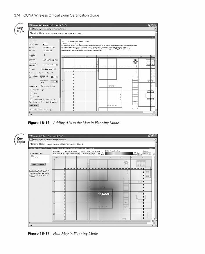
Figure 18-16 Adding APs to the Map in Planning Mode
Figure 18-17 Heat Map in Planning Mode
374 CCNA Wireless Official Exam Certification Guide
Key Topic
Key Topic
21_1587202115_ch18.qxp 9/29/08 2:40 PM Page 374

Figure 18-18 Generating a Proposal
Chapter 18: Enterprise Wireless Management with the WCS and the Location Appliance 375
Figure 18-19 Viewing the First Portion of the Proposal
21_1587202115_ch18.qxp 9/29/08 2:40 PM Page 375

376 CCNA Wireless Official Exam Certification Guide
Figure 18-20 Monitor Menu
Monitoring with the WCSYou can use the WCS to monitor the wireless network. You can use the monitoring pagesto view controllers, APs, and more. Figure 18-20 shows the Monitor menu.
An alarm summary, shown in Figure 18-20, is available and refreshes every 15 seconds.Fields that are clear indicate no alarms. Red is critical, orange is a major alarm, and yellowis a minor alarm.
By clicking an alarm, you can get more details on the situation.
Another valuable resource in the WCS is the capability to troubleshoot clients. SelectMonitor > Clients. Next, place a Client MAC address into the Client MacAddress fieldand click the Troubleshoot button, as shown in Figure 18-21. This allows you to focusyour troubleshooting efforts on the specified client.
You can also monitor rogue APs, security settings, and Radio Resource Management(RRM). In addition, you can monitor Location Appliances. The Location Appliance tightlyintegrates with the WCS and can provide real-time location tracking within about 30 feet.This is an added benefit when troubleshooting issues related to interference and rogues.
Key Topic
21_1587202115_ch18.qxp 9/29/08 2:40 PM Page 376

Chapter 18: Enterprise Wireless Management with the WCS and the Location Appliance 377
Figure 18-21 Client Troubleshooting
Key Topic
21_1587202115_ch18.qxp 9/29/08 2:40 PM Page 377

Complete the Tables and Lists from MemoryPrint a copy of Appendix B, “Memory Tables” (found on the CD) or at least the sectionfor this chapter, and complete the tables and lists from memory. Appendix C, “MemoryTables Answer Key,” also on the CD, includes completed tables and lists to check yourwork.
378 CCNA Wireless Official Exam Certification Guide
Table 18-3 Key Topics for Chapter 18
Key Topic Item Description Page Number
Paragraph from the section “In-stalling and Configuring the WCS”
Lists detailing the requirementsfor install
358
Table 18-2 WCS ports 359
Figure 18-1 The WCS interface 361
Figure 18-3 Configuring controllers in theWCS
363
Paragraph from the section “Working with Templates”
Steps to create a template 364
Paragraph from the section “Working with Templates”
Steps to apply a template to acontroller
365
Figure 18-10 Maps in the WCS 369
Figure 18-13 Heat maps in the WCS 371
Figure 18-14 Accessing the map editor 372
Figure 18-16 Adding APs to the map in Plan-ning Mode
374
Figure 18-17 Heat map in Planning Mode 374
Figure 18-20 Monitor menu 376
Figure 18-21 Client troubleshooting 377
Exam Preparation Tasks
Review All the Key TopicsReview the most important topics from this chapter, noted with the Key Topics icon in theouter margin of the page. Table 18-3 lists a reference of these key topics and the pagenumber where you can find each one.
21_1587202115_ch18.qxp 9/29/08 2:40 PM Page 378

Chapter 18: Enterprise Wireless Management with the WCS and the Location Appliance 379
Definition of Key TermsDefine the following key terms from this chapter, and check your answers in the Glossary:
WCS, Cisco Wireless Location Appliance, WCS templates, auto provisioning, site survey,WCS RF prediction, WCS Planning Mode
ReferencesChapter 10, “Using Templates,” from the Cisco Wireless Control System Configuration
Guide, Release 5.0: http://tinyurl.com/5ust42.
21_1587202115_ch18.qxp 9/29/08 2:40 PM Page 379

This chapter covers the following subjects:
Upgrading a Controller: Describes how to upgrade a Cisco controller.
Upgrading an AP: Looks at how an AP upgradesits image.
Upgrading WCS: Describes how to manage anupgrade of WCS.
Managing Configurations: Covers how to manage configuration files with the controller.
22_1587202115_ch19.qxp 9/29/08 2:46 PM Page 380

CHAPTER 19
Maintaining Wireless Networks
Table 19-1 “Do I Know This Already?” Section-to-Question Mapping
Foundation Topics Section Questions
Upgrading a Controller 1–5
Upgrading an AP 6–7
Upgrading WCS 8
Managing Configurations 9–11
Part of the day-to-day management of a wireless network involves working with images ofthe controllers and access points (AP). Cisco recommends that all controllers run the sameversion of code. In turn, the APs associated with a controller run the same version of codeas the controller. Hence, upgrading or downgrading a controller puts all the APs on thesame version as well. In this chapter, you will learn the steps required to upgrade a con-troller, upgrade an AP, upgrade the Wireless Control System (WCS), and manage configu-ration files.
You should do the “Do I Know This Already?” quiz first. If you score 80 percent or higher,you may want to skip to the section “Exam Preparation Tasks.” If you score below 80 per-cent, you should spend the time reviewing the entire chapter.
“Do I Know This Already?” QuizThe “Do I Know This Already?” quiz helps you determine your level of knowledge of thischapter’s topics before you begin. Table 19-1 details the major topics discussed in thischapter and their corresponding quiz questions.
22_1587202115_ch19.qxp 9/29/08 2:46 PM Page 381

382 CCNA Wireless Official Exam Certification Guide
1. According to the following figure, what version of controller code is in use?
a. 5.0.148.0
b. 192.168.1.50
c. +38 C
d. 4.1.2.60 (Mesh)
2. What do you choose to verify the version of hardware?
a. Controller > General
b. Controller > Inventory
c. Management > Summary
d. Monitor > Summary
22_1587202115_ch19.qxp 9/29/08 2:46 PM Page 382

Chapter 19: Maintaining Wireless Networks 383
3. Which statement about the following figure is true?
a. The AP being viewed is the Lobby-AP.
b. The AP is running in autonomous mode.
c. The AP has a static IP address.
d. The AP is running software version 5.0.148.0.
4. Which extension is used in controller upgrade files?
a. .bin
b. .exe
c. .cfg
d. .aes
5. Which protocols are used to upgrade a controller? (Choose two.)
a. FTP
b. TFTP
c. HTTP
d. SCP
22_1587202115_ch19.qxp 9/29/08 2:46 PM Page 383

6. What does an AP do if a controller is running a higher version of software?
a. It does nothing; they don’t need to be the same.
b. It automatically upgrades to the same version as the controller.
c. It causes the controller to downgrade to the same version as the AP.
d. It reboots continuously and keeps searching for a controller with the same version.
7. If an AP leaves one controller and associates with another, what does it check?
a. The controller’s hardware version
b. How many licenses the controller has
c. The version the controller is running
d. The version that other APs are running
8. The WCS is upgraded using what method?
a. WCS code upgrade script
b. FTP
c. TFTP
d. SCP
9. How do you save the controller’s configuration using the web interface?
a. Choose Commands > Save.
b. Click the Save Configuration link.
c. Choose Commands > Copy-Run-Start.
d. Choose Controllers > Save.
384 CCNA Wireless Official Exam Certification Guide
22_1587202115_ch19.qxp 9/29/08 2:46 PM Page 384

10. If you clicked the Upload button on the page shown in the following figure, whatwould happen?
Chapter 19: Maintaining Wireless Networks 385
a. The controller software would get backed up to an FTP server.
b. The controller configuration would be archived to an NFS server at the IP address 192.168.2.96.
c. The controller configuration would be uploaded in clear text using a TFTP server.
d. The controller configuration would be encrypted and uploaded to 192.168.2.96using TFTP.
11. In what format is the controller configuration file?
a. XML
b. XHTML
c. DHTML
d. Clear text
22_1587202115_ch19.qxp 9/29/08 2:46 PM Page 385

386 CCNA Wireless Official Exam Certification Guide
Foundation Topics
Upgrading a ControllerManagement tasks in the controller involve upgrading or downgrading images as well asmanaging configuration files. You can begin working with these files by verifying the ver-sion currently running on the controller. Figure 19-1 shows the MONITOR > Summarypage, which indicates that the version of code on this particular controller is software ver-sion 4.1.192.17M (Mesh). 5.x is the current version of code, so you need to obtain the ver-sion you want to have loaded before performing the upgrade.
You also need to know the hardware with which you are working. You can find the hard-ware information by choosing CONTROLLER > Inventory and verifying the platform.The platform used in this example is an AIR-WLC4402-12-K9, as shown in Figure 19-2.
For the record, you might as well verify the AP hardware being used. To verify the APsoftware version, choose WIRELESS > All APs, and click the AP name you want to ver-ify. In Figure 19-3, the Lobby-AP has been selected. You see a configuration page withfour tabs:
■ General
■ Inventory
Figure 19-1 Verify the Controller Software Version
Key Topic
22_1587202115_ch19.qxp 9/29/08 2:46 PM Page 386

Chapter 19: Maintaining Wireless Networks 387
Figure 19-2 Verify the Hardware Version
Figure 19-3 General Details for the Lobby-AP
Key Topic
22_1587202115_ch19.qxp 9/29/08 2:46 PM Page 387

388 CCNA Wireless Official Exam Certification Guide
Note Sometimes you have to upgrade through prior releases of software up to the versionyou ultimately want. This is because the older versions of code have a built-in TFTP clientthat does not support file transfers greater than 32 MB. The following URL is a good refer-ence for helping network engineers or administrators determine an upgrade path: http://www.cisco.com/en/US/tech/tk722/tk809/technologies_configuration_example09186a00805f381f.shtml.
■ Interfaces
■ Advanced
The General tab displays the software (S/W) version, as shown in Figure 19-3.
In the figure, the version on the AP is 4.1.192.17M (Mesh), which is the same version thatis running on the controller.
Selecting the Inventory tab displays the hardware version. In this case, the Lobby-AP is anAIR-AP1131AG-A-K9, as shown in Figure 19-4.
Now you have all the version information you need to upgrade the controller software ver-sion. The next step is to determine which upgrade approach you will take.
Controller Upgrade Approaches
You can take two approaches when upgrading the controller. You can use the command-line interface (CLI), or you can use the web-based interface. To keep things simple, we willfocus on the web interface method.
Start by going to the Cisco Software Center (www.cisco.com/go/software) and download-ing the image you want to install. The image should have an .aes extension. This is a com-pressed archive file. Three files are included in the .aes compressed file:
■ RTOS: The controller’s Real-Time Operating System
■ CODE: Airwave Director, command-line interface, and the controller’s switch web interface
■ ppcboot.bin: The controller’s bootloader
The next step is to place the .aes file on a TFTP server. Tftpd32 is a common TFTP serverprogram that can you can obtain from http://tftpd32.jounin.net. As soon as the file is onthe server, and the controller can reach the server, choose COMMANDS > DownloadFile, as shown in Figure 19-5. You see the File Type drop-down. The file type is Code.Next, enter the IP address of the TFTP server, as well as the file path and filename. ClickDownload to begin the process.
Key Topic
22_1587202115_ch19.qxp 9/29/08 2:46 PM Page 388

Chapter 19: Maintaining Wireless Networks 389
Figure 19-4 AP Hardware Version
Figure 19-5 Upgrade the Controller via the Web Interface
Key Topic
22_1587202115_ch19.qxp 9/29/08 2:46 PM Page 389

390 CCNA Wireless Official Exam Certification Guide
Figure 19-6 Verify the Upgrade of the Controller
Note The ping utility is a Windows function, not a function or utility in WCS. To accessthe ping utility, you need to open a command prompt in Windows and enter the ping com-mand followed by the address you want to ping.
As the transfer begins, the page continues to refresh every few seconds. The controllercopies the file to RAM. When it’s finished, the controller puts the file in flash. The exist-ing image then becomes the backup image. As soon as the transfer is complete, you needto reboot the controller. You can click the link displayed on the Download file to Con-troller page. This redirects you to the Reboot page.
After the reboot, log back in, and verify that the new code has been transferred. As shownin Figure 19-6, the software version has been successfully upgraded.
Upgrade Using WCS
You can also use WCS to upgrade the controller. Upgrading the controller also upgradesthe APs, because they sync to the same code. To perform the upgrade, follow these steps:
Step 1. Verify connectivity before you start the upgrade process. Use the ping utilityfrom the WCS to be sure that the WCS server can contact the controller. Also,if you use an external TFTP server, ping it as well.
22_1587202115_ch19.qxp 9/29/08 2:46 PM Page 390

Chapter 19: Maintaining Wireless Networks 391
Step 2. Click Configure > Controllers to navigate to the All Controllers page.
Step 3. Select the check box of the controller you want to upgrade. Choose Select aCommand > Download Software, and click GO. WCS displays the DownloadSoftware to Controller page.
Step 4. If you use the built-in WCS TFTP server, check the TFTP Server on WCS Sys-tem check box. If you use an external TFTP server, uncheck this check box andadd the external TFTP server IP address.
Step 5. Click Browse and navigate to the software update file. The files are uploadedto the root directory that was configured for use by the TFTP server. You canchange to a different directory.
Note You should always double-check the software file you plan to use for your con-troller. Selecting the wrong file can cause problems. Be sure that you have the correct soft-ware file for your controller.
Step 6. Click Download. WCS downloads the software to the controller, and the con-troller writes the code to flash RAM. As WCS performs this function, it dis-plays its progress in the Status field.
Upgrading an APUpgrading an AP is pretty easy. In fact, if you followed the process described in the pre-ceding section, you are already done, because the AP synchronizes to the controller. Re-call that in Figure 19-3 you verified the version of AP software, and it was the same as thecontroller—version 4.1.192.17M (Mesh). After upgrading the controller to software ver-sion 5.0.148.0, you can again verify the client by choosing WIRELESS > All APs andclicking the AP name that you want to verify. In Figure 19-7, the Lobby-AP has been se-lected. According to the information in the Software Version field, it has been upgraded toversion 5.0.148.0, matching that of the controller. Remember that after upgrading the soft-ware on the controller, the APs automatically upgrade their software as well, but only 20APs can upgrade at any given time.
Remember that APs synchronize to the controller. This means the following:
■ If the controller is a higher version, the AP upgrades.
■ If the controller is a lower version, the AP downgrades.
■ If the AP leaves one controller and associates with another, the AP checks the con-troller version and upgrades/downgrades as needed.
Key Topic
22_1587202115_ch19.qxp 9/29/08 2:46 PM Page 391

392 CCNA Wireless Official Exam Certification Guide
Figure 19-7 Verify the AP Upgrade
Upgrading WCSBeginning in WCS version 4.2, the WCS code upgrade script made it possible to upgradethe WCS while retaining the directories, root password, and license information. The op-eration is automated and simply involves downloading the install file from the Cisco web-site and running it on the machine on which the WCS is installed. During the installprocess, you are informed that a previous install has been detected, and you’re asked tochoose between upgrading and installing. Upgrading retains all the information from theprevious install. If you choose the install option, it will be as if WCS was not previouslythere; in other words, it’s a fresh install.
Managing ConfigurationsWhen working in the Cisco Unified Wireless Environment, you deal with a number ofconfiguration files. You potentially have numerous controller configurations as well as APconfigurations. When you’re working with the controller, it’s a good idea to save your con-figuration often. Clicking the Save Configuration link can save a controller’s configura-tion. It is found in the top-right corner of the web interface, as shown in Figure 19-8.
22_1587202115_ch19.qxp 9/29/08 2:46 PM Page 392

Chapter 19: Maintaining Wireless Networks 393
Figure 19-8 Save the Configuration
In addition to saving the configuration to NVRAM, you can back up the configuration ona remote TFTP server. Saving to a TFTP server is similar to how you upgraded the con-troller, only this time you are moving a file in the opposite direction. The setup requiresthe use of TFTP server software installed on the destination computer where you want toback up the file. TFTP uses UDP port 69, so make sure that nothing in the transit path,such as a firewall, might block that type of traffic. If you have already upgraded from theTFTP server, you probably won’t have any issues.
The next step is to choose COMMANDS > Upload File. In the drop-down box, chooseConfiguration. Select the option to encrypt the file is you want, enter the server’s addressand configuration file name, and click upload. If you don’t choose to encrypt it, you get apop-up warning when you click Upload.
After you upload the configuration file, you can download this file to other controllers.However, you cannot read it as you would a configuration file from a router or switch, be-cause it is an XML file.
Suppose you wanted to back up the controller configuration to 192.168.2.99. Simply enterthe IP address 192.168.2.99 in the IP Address field and give it a name, as shown in Figure19-9. In this example, the file name is 1WLC1.cfg.
22_1587202115_ch19.qxp 9/29/08 2:46 PM Page 393

394 CCNA Wireless Official Exam Certification Guide
Click the Upload button to begin the process. This takes a short time. After completion,you can verify by viewing the directory on the TFTP server where the files are stored, asshown in Figure 19-10. After viewing the directory on the TFTP server, you can see thatthe upload was successful. The file has been backed up and can now be used on othercontrollers.
Further exploration shows that the file can be opened and viewed but is not very readable,as shown in Figure 19-11.
If you do want to view the configuration in a readable format, you could issue the showrunning-config command from the CLI on the controller. In Example 19-1, the show running-config command has been entered on the controller. Using this command youcan see line by line how the controller is configured. It’s important to note the differencebetween this command and the show run-config command, because they produce verydifferent output. show running-config displays the contents of the configuration line byline. show run-config provides information about the state of the system.
Figure 19-9 Backing Up the Controller Configuration to TFTP
Key Topic
22_1587202115_ch19.qxp 9/29/08 2:46 PM Page 394

Chapter 19: Maintaining Wireless Networks 395
Figure 19-10 TFTP Directory
Figure 19-11 Viewing the File on the TFTP Server
22_1587202115_ch19.qxp 9/29/08 2:46 PM Page 395

396 CCNA Wireless Official Exam Certification Guide
Example 19-1 show running-config Command Output
(Cisco Controller) > show running-config
802.11a 11nSupport a-mpdu tx priority 0 disable
802.11a cac voice tspec-inactivity-timeout ignore
802.11a cac video tspec-inactivity-timeout ignore
802.11a cac voice stream-size 84000 max-streams 2
802.11b 11nSupport a-mpdu tx priority 0 disable
802.11b cac voice tspec-inactivity-timeout ignore
802.11b cac video tspec-inactivity-timeout ignore
802.11b cac voice stream-size 84000 max-streams 2
aaa auth mgmt local radius
advanced 802.11a receiver pico-cell-V2 rx_sense_thrld 0 0 0
advanced 802.11a receiver pico-cell-V2 cca_sense_thrld 0 0 0
advanced 802.11a receiver pico-cell-V2 sta_tx_pwr 0 0 0
Location Summary
Algorithm used: Average
Client
RSSI expiry timeout: 150 sec
Half life: 60 sec
Notify Threshold: 0 db
Calibrating Client
RSSI expiry timeout: 30 sec
Half life: 0 sec
Rogue AP
RSSI expiry timeout: 120 sec
Half life: 0 sec
Notify Threshold: 0 db
RFID Tag
RSSI expiry timeout: 5 sec
Half life: 0 sec
Notify Threshold: 0 db
location rssi-half-life tags 0
location rssi-half-life rogue-aps 0
location expiry tags 5
location expiry client 150
location expiry calibrating-client 30
location expiry rogue-aps 120
advanced eap identity-request-timeout 1
advanced eap identity-request-retries 20
advanced eap request-timeout 1
ap syslog host global 255.255.255.255
interface create guest_lan 80
interface address ap-manager 192.168.1.51 255.255.255.0 192.168.1.1
interface address dynamic-interface guest_lan 172.30.1.50 255.255.255.0 172.30.1.1
interface address management 192.168.1.50 255.255.255.0 192.168.1.1
22_1587202115_ch19.qxp 9/29/08 2:46 PM Page 396

Chapter 19: Maintaining Wireless Networks 397
interface address service-port 192.168.100.1 255.255.255.0
interface address virtual 1.1.1.1
interface dhcp ap-manager primary 192.168.1.1
interface dhcp dynamic-interface guest_lan primary 172.30.1.1
interface dhcp management primary 192.168.1.1
interface dhcp service-port disable
interface vlan ap-manager 1
interface vlan guest_lan 80
interface vlan management 1
interface port ap-manager 1
interface port guest_lan 1
interface port management 1
load-balancing window 5
logging buffered 1
mesh security eap
mgmtuser add admin **** read-write
mobility group domain CP_Mobile
mobility group anchor wlan add 2 192.168.1.50
mobility dscp value for inter-controller mobility packets 0
network webmode enable
network rf-network-name CP_Mobile
radius fallback-test mode off
radius fallback-test username cisco-probe
radius fallback-test interval 300
snmp version v2c enable
snmp version v3 enable
sysname 1WLC1
wlan create 1 Open Open
wlan create 2 Public_Guest_Access GUESTNET
wlan interface 2 guest_lan
wlan session-timeout 1 1800
wlan session-timeout 2 disable
wlan wmm allow 1
wlan wmm allow 2
wlan security wpa disable 2
wlan security web-auth server-precedence 1
wlan security web-auth server-precedence 2
wlan security wpa akm ft reassociation-time 0 1
wlan security wpa akm ft over-the-air disable 1
wlan security wpa akm ft over-the-ds disable 1
wlan security wpa akm ft reassociation-time 0 2
wlan security wpa akm ft over-the-air disable 2
wlan security wpa akm ft over-the-ds disable 2
wlan enable 1
wlan enable 2
22_1587202115_ch19.qxp 9/29/08 2:46 PM Page 397

398 CCNA Wireless Official Exam Certification Guide
Figure 19-12 Options for Resetting the AP
Working with AP Configuration Files
Keeping in mind that the AP gets its configuration from the controller should make it clearthat you don’t really have to do much to manage AP configurations. However, you mightencounter scenarios where you want to reset an AP to its factory default. You can do thisat the AP itself, but you require physical access to the AP. To reset the AP from the con-troller, simply choose WIRELESS, choose the AP you want to reset, and scroll to the bot-tom. You have two options, as shown in Figure 19-12. You can click Clear All Config orClear Config Except Static IP. The choice depends on what you want to happen. If youuse static IPs and want to reset the AP and remove it from the network, choose the secondoption.
Resetting the Controller to the Defaults
Finally, if you decide to reset the controller to its factory defaults, you can chooseCOMMANDS > Reset to Factory Default. This page presents a message similar to theone shown in Figure 19-13; it explains what happens when you reset the controller to thedefaults. The controller needs to reboot for this to occur, because the configuration is notonly stored in NVRAM, but it is also active in RAM and is cleared only with a reboot.You will lose connectivity when you do this.
22_1587202115_ch19.qxp 9/29/08 2:46 PM Page 398

Chapter 19: Maintaining Wireless Networks 399
Figure 19-13 Reset the Controller to the Factory Defaults
22_1587202115_ch19.qxp 9/29/08 2:46 PM Page 399

400 CCNA Wireless Official Exam Certification Guide
Exam Preparation Tasks
Review All the Key TopicsReview the most important topics from this chapter, denoted with the Key Topic icon.Table 19-2 lists these key topics and the page number where each one can be found.
Definition of Key TermsDefine the following key terms from this chapter, and check your answers in the Glossary:
RTOS, RAM, NVRAM, TFTP
ReferencesCisco Wireless Control System Configuration Guide, Release 5.0: http://www.cisco.com/en/US/docs/wireless/wcs/5.0/configuration/guide/wcstasks.html#wp1076844
Cisco Wireless LAN Controller Configuration Guide, Release 5.0: http://www.cisco.com/en/US/docs/wireless/controller/5.0/configuration/guide/c5mfw.html
Table 19-2 Key Topics for Chapter 19
Key Topic Item Description Page Number
Figure 19-1 Verifying the software version 386
Figure 19-3 General details for the Lobby-AP 387
Paragraph from the section“Controller Upgrade Approaches”
A list of files contained in the compressed upgrade file
388
Figure 19-5 Upgrading the controller via the webinterface
389
Paragraph from the section“Upgrading an AP”
Bullet points about AP upgrades and downgrades
391
Figure 19-9 Backing up the controllerconfiguration to TFTP
394
22_1587202115_ch19.qxp 9/29/08 2:46 PM Page 400

22_1587202115_ch19.qxp 9/29/08 2:46 PM Page 401

This chapter covers the following subjects:
Physical Connections and LEDs: A look at trou-bleshooting using physical features of the network.
Common Client-Side Issues: A discussion ofcommon client issues.
Using the CLI to Troubleshoot: A look at CLIcommands for viewing and debugging using the CLI.
Using the Controller Interface: Details of trou-bleshooting using various web interface pages.
Using WCS Version 5.x to TroubleshootClients: Overview of techniques used to trouble-shoot clients using WCS.
Using the Cisco Spectrum Expert: A brief introduction to the Cisco Spectrum Expert and itsuse.
23_1587202115_ch20.qxp 9/29/08 2:43 PM Page 402

CHAPTER 20
Troubleshooting Wireless Networks
Table 20-1 “Do I Know This Already?” Section-to-Question Mapping
Foundation Topics Section Questions
Physical Connections and LEDs 1–2
Common Client-Side Issues 3–5
Using the CLI to Troubleshoot 6–11
Using the Controller Interface 12–13
Using WCS Version 5.x to Troubleshoot Clients 14
Using the Cisco Spectrum Expert 15
Trouble tends to be something everyone runs into at some point in time. People make ty-pos. Cables mysteriously go bad. Stuff happens. This chapter discusses numerous issuesthat can happen in a wireless network along with some of the techniques, commands, con-figuration pages, and methods that you can use to correct them. Although everyone has aunique style, this chapter helps you hone your skills at recognizing misconfigurations andmaking corrections, using the command-line interface (CLI), the controller interface, andthe Wireless Control System (WCS).
You should do the “Do I Know This Already?” quiz first. If you score 80 percent or higher,you might want to skip to the section “Exam Preparation Tasks.” If you score below 80percent, you should spend the time reviewing the entire chapter. Refer to Appendix A,“Answers to the ‘Do I Know This Already?’ Quizzes,” to confirm your answers.
“Do I Know This Already?” QuizThe “Do I Know This Already?” quiz helps you determine your level of knowledge of thischapter’s topics before you begin. Table 20-1 details the major topics discussed in thischapter and their corresponding quiz questions.
23_1587202115_ch20.qxp 9/29/08 2:43 PM Page 403

404 CCNA Wireless Official Exam Certification Guide
1. At what layers of the OSI model does trouble happen most often?
a. Layer 1
b. Layers 1 through 3
c. Layers 2 through 6
d. Above Layer 7
2. What are some actions regarding physical characteristics that you can use for trou-bleshooting? (Choose all that apply.)
a. Analyze port LEDs
b. Verify wiring
c. Check the internal fans
d. View debugs
3. Which of the following accurately describes the hidden node issue?
a. A node is hidden under a desk and used to attack the wireless network.
b. A node is accessing the network from the parking lot.
c. Two nodes are attempting to send at the same time. They are out of range ofeach other but not of the AP.
d. Nodes on the network access hidden APs.
4. Which of the following best describes the exposed node issue?
a. Two nodes are sending on the same channel to different APs. The cells are tooclose, so a collision occurs.
b. A node is attacking the network in plain view.
c. A node is on the wireless network without antivirus software.
d. A node is listening on undesired ports.
5. When an AP has a greater RF range than a client, the client can see the AP but annotassociate with it because the client frames do not reach the AP. What is this situationknown as?
a. The Weak Antenna syndrome
b. The Weak Link issue
c. The Half Duplex situation
d. The Near/Far issue
6. From where can you execute debug commands?
a. The GUI
b. The CLI
c. The GUI and the CLI
d. The WCS only
23_1587202115_ch20.qxp 9/29/08 2:43 PM Page 404

Chapter 20: Troubleshooting Wireless Networks 405
7. What command provides a summary of clients?
a. show clients
b. show client summary
c. show summary
d. show ap client summary
8. Examine the following output and then answer the question.(Cisco Controller) >show client detail 00:15:af:0a:0b:71
Client MAC Address............................... 00:15:af:0a:0b:71
Client Username ................................. N/A
AP MAC Address................................... 00:1a:a2:fc:df:a0
Client State..................................... Probing
Wireless LAN Id.................................. N/A
BSSID............................................ 00:1a:a2:fc:df:9f
Channel.......................................... 11
IP Address....................................... Unknown
Association Id................................... 0
Authentication Algorithm......................... Open System
Reason Code...................................... 0
Status Code...................................... 0
Session Timeout.................................. 0
Client CCX version............................... No CCX support
Mirroring........................................ Disabled
QoS Level........................................ Silver
Diff Serv Code Point (DSCP)...................... disabled
802.1P Priority Tag.............................. disabled
WMM Support...................................... Disabled
Mobility State................................... None
Mobility Move Count.............................. 0
Security Policy Completed........................ No
--More-- or (q)uit
Policy Manager State............................. START
Policy Manager Rule Created...................... Yes
NPU Fast Fast Notified........................... No
Policy Type...................................... N/A
Based on this output, does the client have full IP connectivity?
a. Yes.
b. No, the client has partial connectivity but no DNS.
c. No, the client has no IP connectivity because he has no IP address.
d. Yes, but the network is down.
23_1587202115_ch20.qxp 9/29/08 2:43 PM Page 405

406 CCNA Wireless Official Exam Certification Guide
9. If you leave a debug turned on, what happens?
a. It consumes all the resources on the controller.
b. It runs continuously.
c. It turns off when the controller reloads.
d. It becomes disabled when the session times out.
10. Look at the following output and answer the question.(Cisco Controller) >debug ?
aaa Configures the AAA debug options.
airewave-director Configures the Airewave Director debug options
ap Configures debug of Cisco AP.
arp Configures debug of ARP.
bcast Configures debug of broadcast.
cac Configures the call admission control (CAC) debug options.
cdp Configures debug of cdp.
crypto Configures the Hardware Crypto debug options.
dhcp Configures the DHCP debug options.
client Enables debugs for common client problems.
disable-all Disables all debug messages.
dot11 Configures the 802.11 events debug options.
dot1x Configures the 802.1X debug options.
iapp Configures the IAPP debug options.
ccxrm Configures the CCX_RM debug options.
ccxdiag Configures the CCX Diagnostic debug options.
Which debug would be used to troubleshoot issues with port-based authentication?
a. arp
b. cdp
c. dot11
d. dot1x
11. How do you enable client troubleshooting?
a. Issue the CLI command debug mac addr mac_address_of_client.
b. Click the Troubleshoot button from the Clients Summary page of the WCS.
c. Select the client from the Clients drop-down menu.
d. Use an access list to match a client and tie it to a debug.
12. Where would you find information equivalent to the show client summary commandwithin the controller interface?
a. MANAGEMENT > Clients
b. CONTROLLER > Clients
c. MONITOR > Clients > Detail
d. WLANs > Clients
23_1587202115_ch20.qxp 9/29/08 2:43 PM Page 406

Chapter 20: Troubleshooting Wireless Networks 407
13. Facility Level 5 is what?
a. USENET
b. SYSLOG
c. FTP DAEMONS
d. KERNEL
14. WCS is used to troubleshoot client-to-AP connectivity. True or false?
a. True
b. False
15. Which of the following devices does the Cisco Spectrum Expert provide informationabout?
a. Microwave ovens
b. RC cars
c. Controllers
d. Wired clients
23_1587202115_ch20.qxp 9/29/08 2:43 PM Page 407

408 CCNA Wireless Official Exam Certification Guide
Foundation Topics
Physical Connections and LEDsTrouble usually happens between Layer 1 and Layer 3 of the OSI reference model. That isnot to say that trouble does not occur at Layers 4 through 7, but Layers 1 through 3 arethe layers where network administrators have the most hands on. Working your way upcan often prove to be a time saver. Starting at Layer 1, physical connectivity can often savevaluable time. You can begin by visually examining the physical connections. Keep inmind all that is involved in the path of your traffic. This can include areas related to thefollowing:
■ AP to switch
■ Switch to switch
■ Switch to controller
■ Controller to distribution
While you are examining the physical connectivity, note the port LED status of each de-vice. What do the LEDs indicate? Are they green? Are they amber? Are they red? Eachdevice has different LEDs; for example, the LEDs on a controller are different from theLEDs on an AP, yet they all have somewhat of a common color coding. Usually red is bad,amber is not so good, and green is okay. Look up the Cisco documentation for details foreach product that you work with. The “References” section at the end of this chapter in-cludes some valuable links that can help you determine issues in the network and correctthem, some using the port LEDs for verification.
After you have verified the physical connections, you can work in one of two directions:
■ Verification from the client back to the controller
■ Verification from the controller to the client
In either case, common issues arise. You might find that connectivity issues are not relatedto the wireless network at all, but rather the distribution network, gateway, or Internetservice provider (ISP). Regardless, the ability to isolate problems is a requirement of thoseseeking the CCNA Wireless certification. The next section explores some common client-side issues.
Common Client-Side IssuesClient-side issues arise frequently and are often expressed in vague ways, for example, “Icannot get to the Internet.” “Okay,” you might think, “What does that mean?” The answermight not always be clear, but you can verify some values to quickly restore connectivityfor end users.
Note: When I worked for a large service provider, we went through a transition from bridgesto switches. During the initial deployment, none of the administrators on the local-area
23_1587202115_ch20.qxp 9/29/08 2:43 PM Page 408

Chapter 20: Troubleshooting Wireless Networks 409
network knew about the Spanning Tree Protocol (STP) or the effects it had when a devicewas connected to a switchport.
I recall that first week, sitting in my little cubicle at 7:55 a.m. and hearing the voices of mycolleagues say, “The Internet is down.” And then, of course, someone would call IT and saythat nobody could get to the Internet and that he thought the Internet was down. I feltsorry for the IT guys, because nobody called them and said, “When I came in this morningand turned on my computer, Spanning Tree put all the ports into a blocking mode while ver-ifying that there was no loop, so none of us could get to the Internet for about one minute.”Had someone done that, the IT guys could have simply enabled PortFast on all the clientports and solved the problem. My point? Users do not call and give you the answer to theproblem. Instead, they give you a symptom, and it is up to you to decipher the true issue re-gardless of how vague the symptom they described is. Now enough of my reminiscing.What can you do to isolate these issues?
Some of the more common issues that you can verify include the following:
■ Check that the client card is enabled. Many laptops have a hardware switch that dis-ables the wireless card internally, which can cause issues.
■ Check that service set identifiers (SSIDs) are not incorrectly configured.
■ Verify whether the client is using a radio that is not enabled on the AP.
■ Verify whether the MAC address of the client is being “blacklisted” on the network.
■ If using 802.1x, verify whether the client side is configured to support the networkmethod, such as Extensible Authentication Protocol-Transport Layer Security (EAP-TLS) with certificates.
■ Verify whether the client is getting an IP address that is blocked by an access controllist (ACL) somewhere else in the network.
■ Check the client firewall or antivirus software, because it might be blocking access.There might not be much you can do other than asking the client to turn each ofthese off temporarily for testing.
■ If performing Network Access Control (NAC), check whether the client is posturingproperly. Check the Authentication, Authorization, and Accounting (AAA) server orthe Monitoring, Analysis, and Response System (MARS) logs to determine this. Froma wireless perspective, there is not much you can do except have the users access a“Guest” type of network that does not require security posturing.
Note: Cisco Security MARS provides security monitoring for network devices and hostapplications supporting both Cisco and other vendors. You can find out more about it athttp://tinyurl.com/bfr64.
■ If you are using preshared keys for wireless authentication, verify that they are cor-rectly configured on the client side. Also, verify that they are configured for the cor-rect length.
23_1587202115_ch20.qxp 9/29/08 2:43 PM Page 409

410 CCNA Wireless Official Exam Certification Guide
Checking these common issues can shorten the time that you spend troubleshooting.
Other problems, however, include one issue called the Hidden Node issue. This happenswhen more than one client tries to send on the same channel at the same time. This issuearises because the two clients are in range of the AP but not each other. The result is thatthey both send, and a collision occurs.
Methods of mitigating this issue include reducing the maximum frame size, forcing a re-quest to send/clear to send (RTS/CTS), and reducing the transmit power of the AP andshrinking the cell. In some cases, obstacles cause the devices not to see each other. Inthese scenarios, you might need to remove the obstacle; however, sometimes removing awall is not an option. In these cases, take the other measures mentioned. The goal is to ei-ther get the clients to hear each other (or an RTS/CTS) so they do not sent at the sametime or to get them onto different APs and operating on different channels. By shrinkingthe cell, you get the clients on different channels, but by lowering the transmit power, youmight need to add more APs to fully cover the area. By forcing an RTS/CTS, the clientsstill might be on the same channel, but at least they are not stepping on the toes of theother.
Another common issue is called the Exposed Node issue, which occurs when you havetwo wireless cells on the same channel and they are too close to each other. This happensoften in Wireless B/G networks because only three nonoverlapping channels exist. Ifclients in either of the overlapping cells transmit packets, a collision can occur. The simplefix to this is to change your topology, or at least the channel allocation. In some cases thisis not a possibility, so you might consider a change to an 802.11a deployment, where morechannels are available for allocation.
Another issue that happens between clients and APs is the Near/Far issue, which iscaused by an AP transmitter being more powerful than the client transmitter. When aclient sees an AP, because of its strong signal, it attempts to associate with it. Because theclient transmitter is weaker than the AP, it does not have the range that the AP does. Thismeans that the client transmission does not reach the AP, and the association fails. Youcan solve this problem using features of the controller. The controller can help monitor theclient signal and adjust the radio resources as needed.
Additionally, as you might have been expecting, backward compatibility is an issue. Thisissue occurs when an 802.11b client joins the 802.11g cell and when an 802.11b/g/a cliententers an 802.11n cell. The normal symptom is overall degraded data rates. To solve this is-sue, you can lock in a G-only cell for G clients.
Using the CLI to TroubleshootSometimes resolving the common issues is not easy and they require further research. Inthese cases, you can use the CLI or the GUI tool to gather additional information. Fromthe CLI, you have a few options for troubleshooting. First, you can use show commandson the CLI to gain valuable information related to the operational status of the controller,the APs, and the clients. Many of these show commands are available in various pages ofthe GUI tool, as you will see in later sections of this chapter.
Key Topic
Key Topic
Key Topic
23_1587202115_ch20.qxp 9/29/08 2:43 PM Page 410

Chapter 20: Troubleshooting Wireless Networks 411
Some of the show commands you should be familiar with include the following:
■ show client summary
■ show client detail
Example 20-1 shows the output from a show client summary command. In this output,you can see clients that are associated or trying to associate to the network. The examplehas an 802.11b client with the MAC address 0:13:e8:a9:e1:29 that is probing but not asso-ciated with an AP. Furthermore, the client is seen by the AP “Lobby-AP.”
Example 20-1 Viewing the Client Summary
(Cisco Controller) >show client summary
Number of Clients................................ 1
MAC Address AP Name Status WLAN Auth Protocol Port
----------------- ----------------- ------------- ---- ---- -------- ----
00:13:e8:a9:e1:29 Lobby-AP Probing N/A No 802.11b 1
(Cisco Controller) >
How can this assist you in the troubleshooting process? Well, suppose that a client re-ports a problem associating, and as you further research the issue, you find that the APMAC address is seen by the Lobby-AP, and it is usually associated with the Research-LabAP. You might then ask if the client is trying to connect while in the lobby. Who knowswhere this might lead you, but at least you have more information than when youstarted—information that might lead to a resolution.
If you wanted to dig even deeper into the client information, you might use the showclient detail command. Example 20-2 shows the output of this command. Note the addi-tional information you can gain there. Information includes the client username if applica-ble, mobility information if applicable, and much more.
Example 20-2 Viewing Client Details
(Cisco Controller) >show client detail 00:15:af:0a:0b:71
Client MAC Address............................... 00:15:af:0a:0b:71
Client Username ................................. N/A
AP MAC Address................................... 00:1a:a2:fc:df:a0
Client State..................................... Probing
Wireless LAN Id.................................. N/A
BSSID............................................ 00:1a:a2:fc:df:9f
Channel.......................................... 11
IP Address....................................... Unknown
Association Id................................... 0
Authentication Algorithm......................... Open System
Reason Code...................................... 0
continues
Key Topic
Key Topic
23_1587202115_ch20.qxp 9/29/08 2:43 PM Page 411

412 CCNA Wireless Official Exam Certification Guide
Status Code...................................... 0
Session Timeout.................................. 0
Client CCX version............................... No CCX support
Mirroring........................................ Disabled
QoS Level........................................ Silver
Diff Serv Code Point (DSCP)...................... disabled
802.1P Priority Tag.............................. disabled
WMM Support...................................... Disabled
Mobility State................................... None
Mobility Move Count.............................. 0
Security Policy Completed........................ No
—More— or (q)uit
Policy Manager State............................. START
Policy Manager Rule Created...................... Yes
NPU Fast Fast Notified........................... No
Policy Type...................................... N/A
Encryption Cipher................................ None
Management Frame Protection...................... No
EAP Type......................................... Unknown
Interface........................................ management
VLAN............................................. 0
Client Capabilities:
CF Pollable................................ Not implemented
CF Poll Request............................ Not implemented
Short Preamble............................. Not implemented
PBCC....................................... Not implemented
Channel Agility............................ Not implemented
Listen Interval............................ 0
Client Statistics:
Number of Bytes Received................... 0
Number of Bytes Sent....................... 0
Number of Packets Received................. 0
Number of Packets Sent..................... 0
Number of Policy Errors.................... 0
Radio Signal Strength Indicator............ Unavailable
—More— or (q)uit
Signal to Noise Ratio...................... Unavailable
Nearby AP Statistics:
TxExcessiveRetries: 0
TxRetries: 0
RtsSuccessCnt: 0
RtsFailCnt: 0
TxFiltered: 0
TxRateProfile: [0,0,0,0,0,0,0,0,0,0,0,0]
Research_Lab-AP(slot 0) ...................
Example 20-2 Viewing Client Details (continued)
23_1587202115_ch20.qxp 9/29/08 2:43 PM Page 412

Chapter 20: Troubleshooting Wireless Networks 413
antenna0: 5 seconds ago -93 dBm.................. antenna1: 4293918453 seconds ago
-128 dBm
Lobby-AP(slot 0) ..........................
antenna0: 4293918453 seconds ago -128 dBm........ antenna1: 5 seconds ago -94 dBm
Although this information is valuable, it is important to note that it is static. In otherwords, the information you gain from show commands gives you the state or the condi-tions of the network at the time that you enter the command. If you require real-time in-formation, debugs come in handy.
If you have come from the routing world, you are probably familiar with the use of debugcommands and how invaluable they are in troubleshooting. If you are working your waythrough the certification program, and you are doing it in order (CCNA > CCNA Wire-less), then you learned in the CCNA curriculum how a debug command is used in somebasic troubleshooting scenarios. The concept of debug commands carries over here to thewireless space. Available only from the CLI, debug commands can be used on the con-troller to help troubleshoot issues. The principle in the use of debug commands is thesame:
■ Do not leave them on, because they are CPU intensive.
■ Be prepared to turn them off. Sometimes the output is overwhelming.
■ Debug commands take priority over other processes on the controller.
If you think that some debug commands might already be enabled, use the show debugcommand to verify that notion. One fail-safe that is in place is that if you do turn on adebug command and forget about it, the debug becomes disabled when the CLI sessiontimes out. Although this is a good fail-safe, you should still turn your debug commandsoff when you are done with them. To see a list of the available debug commands, use thedebug ? command, as seen in Example 20-3. You can use this to determine which debugcommand is appropriate for the situation; for example, if you are troubleshooting a port-based authentication problem, you might enable debug dot1x.
Example 20-3 Viewing Available debug Commands
(Cisco Controller) >debug ?
aaa Configures the AAA debug options.
airewave-director Configures the Airewave Director debug options
ap Configures debug of Cisco AP.
arp Configures debug of ARP.
bcast Configures debug of broadcast.
cac Configures the call admission control (CAC) debug options.
cdp Configures debug of cdp.
crypto Configures the Hardware Crypto debug options.
dhcp Configures the DHCP debug options.
client Enables debugs for common client problems.
disable-all Disables all debug messages.
continues
Example 20-2 Viewing Client Details (continued)
23_1587202115_ch20.qxp 9/29/08 2:43 PM Page 413

414 CCNA Wireless Official Exam Certification Guide
dot11 Configures the 802.11 events debug options.
dot1x Configures the 802.1X debug options.
iapp Configures the IAPP debug options.
ccxrm Configures the CCX_RM debug options.
ccxdiag Configures the CCX Diagnostic debug options.
locp Configures the LOCP debug options.
l2roam Configures the L2 Roam debug options.
l2age Configures debug of Layer 2 Ago Timeout Messages.
lwapp Configures the LWAPP debug options
mac Configures MAC debugging
--More-- or (q)uit
To really hone in on where the issues are, you can use debug commands for a specific APor a specific client. This requires placing the controller into client troubleshooting mode.To do this, begin by telling the controller, by way of a CLI command, that you want to de-bug for a specific MAC address. For example, to tell the controller that it will be debug-ging for MAC address 00:1a:a2:f9:ed:d0, enter the following:
(Cisco Controller) >debug mac addr 00:1a:a2:f9:ed:d0
The next step is to tell the controller which debug to use for that particular MAC address.For example, if you want to debug LWAPP events for the MAC address 00:1a:a2:f9:ed:d0,use the debug lwapp command as shown here:
(Cisco Controller) >debug lwapp events enable
To verify that the debug command is enabled, use the show debug command, as seen inExample 20-4.
Example 20-4 Verifying Enabled Debugs
(Cisco Controller) >show debug
MAC address ................................ 00:1a:a2:f9:ed:d0
Debug Flags Enabled:
arp error enabled.
bcast error enabled.
lwapp events enabled.
lwapp errors enabled.
Then you wait for an LWAPP event to occur. In Example 20-5, an LWAPP event has oc-curred, and a message has been sent to the console.
Example 20-5 Controller Debug Output
(Cisco Controller) >Wed Jun 25 19:50:50 2008: 00:1a:a2:f9:ed:d0 Received LWAPP
ECHO_REQUEST from AP 00:1a:a2:f9:ed:d0
Wed Jun 25 19:50:50 2008: 00:1a:a2:f9:ed:d0 Successfully transmission of LWAPP
Echo-Response to AP 00:1a:a2:f9:ed:d0
Wed Jun 25 19:50:50 2008: 00:1a:a2:f9:ed:d0 Received LWAPP PRIMARY_DISCOVERY_REQ
from AP 00:1a:a2:f9:ed:d0
Key Topic
Key Topic
Example 20-3 Viewing Available debug Commands (continued)
Key Topic
23_1587202115_ch20.qxp 9/29/08 2:43 PM Page 414

Chapter 20: Troubleshooting Wireless Networks 415
Wed Jun 25 19:50:50 2008: 00:1a:a2:f9:ed:d0 Received LWAPP RRM_DATA_REQ from AP
00:1a:a2:f9:ed:d0
Wed Jun 25 19:50:50 2008: 00:1a:a2:f9:ed:d0 Successfully transmission of LWAPP
Airewave-Director-Data Response to AP 00:1a:a2:f9:ed:d0
Wed Jun 25 19:51:14 2008: 00:1a:a2:f9:ed:d0 Received LWAPP RRM_DATA_REQ from AP
00:1a:a2:f9:ed:d0
Wed Jun 25 19:51:14 2008: 00:1a:a2:f9:ed:d0 Successfully transmission of LWAPP
Airewave-Director-Data Response to AP 00:1a:a2:f9:ed:d0
The actual output of the debug in the example is pretty normal. What is important, how-ever, is that you understand how to enable the debug process, verify it, and turn it off. Todisable the debug process, use the debug disable-all command, as seen in Example 20-6.First the debug process was verified with the show debug command, and then it was dis-abled. After the debug process was disabled, the command show debug was again used toverify that it was in fact disabled.
Example 20-6 Verify the Enabled Debugs
(Cisco Controller) >show debug
MAC address ................................ 00:1a:a2:f9:ed:d0
Debug Flags Enabled:
arp error enabled.
bcast error enabled.
lwapp events enabled.
lwapp errors enabled.
(Cisco Controller) >debug disable-all
(Cisco Controller) >show debug
MAC debugging .............................. disabled
Debug Flags Enabled:
(Cisco Controller) >
When you let the session time out, even though it turns off the debug command, it stillleaves the command to perform client troubleshooting, as seen in Example 20-7. Thismeans that if you enable a new debug command, it only debugs for the client you specify.
Example 20-7 Command to Perform Client Troubleshooting Remains
Connection to 192.168.1.50 closed.
terminal$:
terminal$:
terminal$:ssh 192.168.1.50
continues
Example 20-5 Controller Debug Output (continued)
23_1587202115_ch20.qxp 9/29/08 2:43 PM Page 415

416 CCNA Wireless Official Exam Certification Guide
(Cisco Controller)
User: admin
Password:*****
(Cisco Controller) >show debug
MAC address ................................ 00:1a:a2:f9:ed:d0
Debug Flags Enabled:
As you can see, the connection was closed, essentially timing out. After authenticatingagain to the CLI of the controller, the show debug command was entered. This commandoutput indicates that the MAC address 00:1a:a2:f9:ed:d0 is still enabled for client debug-ging. The point here is that it is always best to turn off debug commands when you arefinished using them. You can also turn off a specific debug command using the disableoption at the end of the command. For example, to turn off the LWAPP debug that wasused in the previous examples, you would use the debug lwapp events disable command.
When you are comfortable turning debug commands on and off, you can explore debugcommands such as debug dot11. The debug dot11 command helps you troubleshoot802.11 parameters, such as these:
■ Mobility
■ Rogue detection
■ Load balancing events
In Example 20-8, you can see a client that has successfully associated.
Example 20-8 A Successful Association
Fri Aug 8 15:32:54 2008: 00:1e:c2:ab:14:26 apfPemAddUser2 (apf_policy.c:209)
Changing state for mobile 00:1e:c2:ab:14:26 on AP 00:1a:a2:f9:ed:d0 from
Associated to Associated
Fri Aug 8 15:32:54 2008: 00:1e:c2:ab:14:26 New client (policy)
Fri Aug 8 15:32:54 2008: 00:1e:c2:ab:14:26 Stopping deletion of Mobile Station:
(callerId: 48)
Fri Aug 8 15:32:54 2008: 00:1e:c2:ab:14:26 Sending Assoc Response to station on
BSSID 00:1a:a2:f9:ed:d0 (status 0)
Fri Aug 8 15:32:54 2008: 00:1e:c2:ab:14:26 apfProcessAssocReq (apf_80211.c:4149)
Changing state for mobile 00:1e:c2:ab:14:26 on AP 00:1a:a2:f9:ed:d0 from
Associated to Associated
Fri Aug 8 15:32:54 2008: 00:1e:c2:ab:14:26 802 new client 00:1e:c2:ab:14:26
Example 20-5 Command to Perform Client Troubleshooting Remains (continued)
23_1587202115_ch20.qxp 9/29/08 2:43 PM Page 416

Chapter 20: Troubleshooting Wireless Networks 417
Figure 20-1 Viewing the Client Summary
Fri Aug 8 15:32:55 2008: 00:1e:c2:ab:14:26 LBS Client data rcvd from AP
00:1a:a2:f9:ed:d0(0) with RSSI (A -128, B -36), SNR 57
Fri Aug 8 15:32:55 2008: 00:1e:c2:ab:14:26 LBS change cur RSSI B -44 , prev -47,
send notify
In this small output, you can see that the client has become associated. One aspect oftroubleshooting might involve connectivity. With this output, you can see that the clientis in fact associated. If the client still has connectivity issues, you would want to startlooking at the wired network, working your way from the controller, then to the switch,then to the next hop router, and so on.
You can also use debugs such as debug dhcp if you are having issues with clients obtain-ing IP addresses. If you are having authentication issues, you might use the debug aaa ordebug dot1x commands.
Using the Controller InterfaceThe controller has several tools to help troubleshoot. From the controller interface, youcan use controller logs, SNMP to alert administrators to current issues, and the Tech Sup-port Pages. In the section “Using the CLI to Troubleshoot,” you looked at output of aclient that was trying to associate. You can see a web interface equivalent to the showclient summary command in Figure 20-1.
Key Topic
Example 20-8 A Successful Association (continued)
23_1587202115_ch20.qxp 9/29/08 2:43 PM Page 417

418 CCNA Wireless Official Exam Certification Guide
Figure 20-2 Viewing the Controller Logs
Here you can gain information about the client, the WLAN the client is on, and othervaluable information for troubleshooting.
Using the Controller Logs
Another valuable resource is the controller logs. Controller logs allow you to see eventsthat have occurred at various levels. You probably want to send these to a Syslog server,but you can view them on the controller by going to MANAGEMENT > Logs > Mes-sage logs. Figure 20-2 shows just a sample of the information that you can obtain here.
To change the way logging is configured, browse to MANAGEMENT > Logs > Config.This configuration page is shown in Figure 20-3. You cant see it inf Figure 20-3, but by se-lecting the Syslog check box, you can point to an external server by entering the addressin the Syslog Server IP Address field.
Note: If you do not already have a Syslog server, you can download kiwi from http://www.kiwisyslog.com. Kiwi is a free Syslog server that many people use.
In addition, from the Syslog Configuration page, you can set the level of logging bychanging the facility levels. These levels control how much information is captured. Ingeneral, the larger the facility number, the more information that is recorded; however, thisis not always the case. Table 20-2 shows the available facility levels.
Key Topic
23_1587202115_ch20.qxp 9/29/08 2:43 PM Page 418

Chapter 20: Troubleshooting Wireless Networks 419
Table 20-2 Available Facility Levels
Facility Name Facility Level
Kernel 0
User Process 1
Mail 2
System Daemons 3
Authorization 4
Syslog 5
Line Printer 6
USENET 7
Unix-to-Unix Copy 8
Cron 9
— 10
FTP Daemons 11
System Use 1 12
System Use 2 13
System Use 3 14
System Use 4 15
Local Use 0 16
Local Use 1 17
Local Use 2 18
Local Use 3 19
Local Use 4 20
Local Use 5 21
Local Use 6 22
Local Use 7 23
23_1587202115_ch20.qxp 9/29/08 2:43 PM Page 419

420 CCNA Wireless Official Exam Certification Guide
Figure 20-3 Configuring Syslog
You can locally view the logs by selecting MANAGEMENT > Logs > Message logs. Themessage logs include information related to the network infrastructure, client issues, au-thentication issues, and AP association issues. These have relevance to the controller.
Using SNMP
When using SNMP gets/sets, you can obtain information about the status of the controllerand allows you to remotely manage the controller. To set up SNMP, go to MANAGEMENT >SNMP > General. Here you configure the following parameters, as shown in Figure 20-4:
■ Name
■ Location
■ Contact
■ System Description
■ System Object ID
■ SNMP Port Number
■ Trap Port Number
■ SNMP v1 Mode
■ SNMP v2c Mode
■ SNMP v3 Mode
23_1587202115_ch20.qxp 9/29/08 2:43 PM Page 420

Chapter 20: Troubleshooting Wireless Networks 421
Figure 20-4 SNMP Configuration on Controllers
Configuring the Community Strings
When you set up SNMP, two community names exist by default. Public is for read-onlyaccess, and Private is for read/write access. If you have any involvement in security, you al-ready know that you should change these values. They are well-known values that an at-tacker can use to gain control of your controller. You can modify the values in thecontroller by choosing MANAGEMENT > SNMP > Communities.
You can also set the SNMPv3 users and trap receivers. Although it is not covered here, itis recommended that you use SNMPv3, because it is the most secure method at the mo-ment.
To view the SNMP trap logs, go to MANAGEMENT > SNMP > Trap Logs. Figure 20-5shows a sample of the SNMP trap logs.
You can use these trap logs to troubleshoot client association failures and AP associationfailures. The trap logs generate a reason code that can point you in the right direction tocorrect the issue. Another way to refine the information you receive is by using the TrapControls found at MANAGEMENT > SNMP > Trap Controls. Here you can controlwhat events generate a trap.
23_1587202115_ch20.qxp 9/29/08 2:43 PM Page 421

422 CCNA Wireless Official Exam Certification Guide
Using Tech Support
You might also find the Tech Support Pages, found at MANAGEMENT > Tech Support,to be of benefit. Although Cisco TAC uses most of what you do here, you might find itbeneficial information for troubleshooting.
Crash logs, which the controller maintains, are created when a system fails. You cannotuse most of the information found in the logs without Cisco TAC assistance. If Cisco TACrequest these logs, you can access them by going to MANAGEMENT > Tech Support >Controller Crash. Five crash dump files can be stored on a controller at any given time.
APs also create a crash log file that the controller can download. Go to MANAGEMENT> Tech Support >AP Crash Log > Get Log to retrieve it. TAC also uses the AP crash logs.
Figure 20-5 SNMP Trap Logs
23_1587202115_ch20.qxp 9/29/08 2:43 PM Page 422

Chapter 20: Troubleshooting Wireless Networks 423
Using WCS Version 5.x to Troubleshoot ClientsYou can use WCS to troubleshoot wireless deployments. Use the Monitor > Client pageto troubleshoot clients. You can see this page in Figure 20-6. When you use this tool, youget a Summary page with a list of problems and corresponding solutions. The page alsohas a log analysis and a detailed event history.
You can use the alarms to troubleshoot. In the Clients Summary page, click the numerousalarms in the lower left to be taken to that Alarm page. Figure 20-6 shows several criticalalarms.
Using the Cisco Spectrum ExpertCisco Spectrum Expert addresses the problem of RF interference in wireless networks.With Cisco Spectrum Expert, you can detect, classify, locate, and manually mitigatesources of wireless interference.
The Cisco Spectrum Expert Wi-Fi is the industry-leading spectrum intelligence productfor Wi-Fi networks. Cisco Spectrum Expert Wi-Fi offers complete visibility into the RFphysical layer in the 2.4-GHz and 5-GHz frequencies, allowing for enhanced performance,security, and reliability of WLAN services.
Figure 20-6 Critical Alarms
23_1587202115_ch20.qxp 9/29/08 2:43 PM Page 423

424 CCNA Wireless Official Exam Certification Guide
The Cisco Spectrum Expert Wi-Fi includes the following components:
■ Cisco Spectrum Expert Wi-Fi sensor
■ Cisco Spectrum Expert software
■ Cisco Spectrum Expert antenna
The Cisco Spectrum Expert Wi-Fi sensor is a sensor in the CardBus card form factor fornotebooks. It is supported on Microsoft Windows–based laptops and delivers compre-hensive spectrum intelligence. Network administrators can streamline wireless networktroubleshooting with better visibility into the RF spectrum and can easily identify and de-tect sources of wireless interference.
Cisco Spectrum Expert provides a comprehensive list of all access points, ad hoc net-works, and interferer devices (for example, microwave ovens, cordless phones, wireless se-curity cameras, Bluetooth devices, and RF jammers).
Cisco Spectrum Expert also gives you a Channel Summary that provides visibility of RFactivity—such as power levels and presence of 802.11 and interferer devices—on a channel-by-channel basis.
The Devices View provides a deeper look at each device and its impact to the wireless net-work, including power level, channel coverage, and other data.
A Device Finder tracks down the location of devices, causing wireless interferencethroughout your enterprise. The Device Classifier offers the most comprehensive classifi-cation of the RF devices, which include the following:
■ Wi-Fi access points
■ In-network devices
■ Known devices
■ Unknown devices
■ Ad hoc devices
■ Wi-Fi stations
■ A variety of Bluetooth devices
■ A variety of cordless phones1
■ Microwave ovens
■ Generic fixed-frequency devices
■ Generic frequency-hopped devices
■ Generic continuous transmitters (for example, FM phones, NTSC video devices)
■ RF jamming devices
■ 802.11FH devices
■ Analog video devices
23_1587202115_ch20.qxp 9/29/08 2:43 PM Page 424

Chapter 20: Troubleshooting Wireless Networks 425
The Spectrum Views create plots and charts for a direct view into the RF spectrum, includ-ing measurements of RF power and network device activity. The plots are especially usefulto trained RF engineers, and the charts are informative for both the expert RF engineer andthe generalist network engineer.
An Alarms Setting configures enterprise-specific alerts and alarm triggers to notify youwhen wireless network is at critical utilization points.
All this is integrated with Cisco WCS and is based on obtaining a license to integrate it.
23_1587202115_ch20.qxp 9/29/08 2:43 PM Page 425

426 CCNA Wireless Official Exam Certification Guide
Exam Preparation Tasks
Review All the Key TopicsReview the most important topics from this chapter, noted with the Key Topics icon in theouter margin of the page. Table 20-3 lists a reference of these key topics and the pagenumber where you can find each one.
Complete the Tables and Lists from MemoryPrint a copy of Appendix B, “Memory Tables,” (found on the CD) or at least the sectionfor this chapter, and complete the tables and lists from memory. Appendix C, “MemoryTables Answer Key,” also on the CD, includes completed tables and lists to check yourwork.
Table 20-3 Key Topics for Chapter 20
Key Topic Item Description Page Number
Paragraph from the section“Common Client-Side Issues”
Discussion of the Hidden Nodeissue
410
Paragraph from the section“Common Client-Side Issues”
Discussion of the ExposedNode issue
410
Paragraph from the section“Common Client-Side Issues”
Discussion of the Near/Far issue 410
Example 20-1 Viewing the client summary 411
Example 20-2 Viewing client details 411
Command syntax Enable client troubleshooting 414
Command syntax Debug LWAPP events 414
Example 20-4 Verify enabled debugs 414
Figure 20-1 Viewing the client summary 417
Figure 20-2 Viewing the controller logs 418
23_1587202115_ch20.qxp 9/29/08 2:43 PM Page 426

Chapter 20: Troubleshooting Wireless Networks 427
Definition of Key TermsDefine the following key terms from this chapter, and check your answers in the Glossary:
Hidden Node issue, Exposed Node issue
References“Troubleshooting TechNotes” at Cisco.com: http://tinyurl.com/6dqxj2
“Troubleshooting Connectivity in a Wireless LAN Network” at Cisco.com: http://tinyurl.com/6l2ob2
The Cisco Spectrum Expert at Cisco.com: http://tinyurl.com/5eja7f
23_1587202115_ch20.qxp 9/29/08 2:43 PM Page 427

24_1587202115_part4.qxd 9/29/08 2:46 PM Page 428

Chapter 21 Final Preparation
Part IV: Final Preparation
24_1587202115_part4.qxd 9/29/08 2:46 PM Page 429

25_1587202115_ch21.qxp 9/29/08 2:39 PM Page 430

CHAPTER 21
Final Preparation
This book has covered the technologies, protocols, commands, and features required foryou to be prepared to pass the CCNA Wireless exam. Although this book supplies de-tailed information, most people need more preparation than simply reading a book. Thischapter details a set of tools and a study plan that can help you complete your preparationfor the exam.
If you’re preparing for the CCNA Wireless exam, you should have already passed the CCNAlevel exams, either the CCNA exam or the ICND1 and ICND2 exams. For information onpassing the CCNA exams, refer to CCENT/CCNA ICND1 Official Exam Certification Guideor CCNA ICND2 Official Exam Certification Guide, or go to http://www.cisco.com/go/ccna.
This short chapter has two main sections. The first lists the exam preparation tools that areuseful at this point in your study process. The second section lists a suggested study plannow that you have completed the rest of the chapters.
Note: This chapter refers to many of the chapters and appendixes included with thisbook, as well as tools available on the CD. Appendixes B and C are included only on the CDthat comes with this book. To access those, just insert the CD and make the appropriate se-lection from the opening interface.
Tools for Final PreparationThis section describes the available tools and how to access them.
Exam Engine and Questions on the CD
The CD in the back of the book includes an exam engine—software that displays andgrades a set of exam-realistic questions. The question database includes simulation (sim)questions, drag-and-drop questions, and many scenario-based questions that require thesame level of analysis as the questions on the CCNA Wireless exam. Using the exam en-gine, you can either study by practicing using the questions in Study Mode, or take a sim-ulated (timed) CCNA Wireless exam.
The installation process has two major steps. The CD in the back of this book has a recentcopy of the exam engine software, supplied by Boson Software (http://www.boson.com).The practice exam—the database of CCNA Wireless exam questions—is not on the CD.Instead, the practice exam resides on the www.boson.com web server, so the second ma-jor step is to activate and download the practice exam.
25_1587202115_ch21.qxp 9/29/08 2:39 PM Page 431

432 CCNA Wireless Official Exam Certification Guide
Install the Software from the CD
The software installation process is pretty routine as compared with other software instal-lation processes. The following list outlines the steps:
Step 1. Insert the CD into your PC.
Step 2. The software that automatically runs is the Cisco Press software to access anduse all CD-based features, including the exam engine, viewing a PDF of thisbook, and viewing the CD-only appendixes. From the main menu, click the op-tion to IInnssttaallll tthhee EExxaamm EEnnggiinnee.
Step 3. Respond to the prompt windows as you would with any typical software in-stallation process.
The installation process might give you the option to register the software. This processrequires that you establish a login at the www.boson.com website. You need this login toactivate the exam, so feel free to register when prompted.
Activate and Download the Practice Exam
After the exam engine is installed, you should activate the exam associated with this book:
Step 1. Start the Boson Exam Engine (BEE) software from the Start menu.
Step 2. The first time you start the software, it should ask you to either log in or registeran account. If you do not already have an account with Boson, select the optionto register a new account. (You must register to download and use the exam.)
Step 3. After you are registered, the software might prompt you to download the lat-est version of the software, which you should do. Note that this process up-dates the exam engine software (formally called the Boson ExamEnvironment), not the practice exam.
Step 4. To activate and download the exam associated with this book, from the examengine main window, click the EExxaamm WWiizzaarrdd button.
Step 5. From the Exam Wizard pop-up window, select AAccttiivvaattee aa ppuurrcchhaasseedd eexxaamm andclick the NNeexxtt button. (Although you did not purchase the exam directly, youpurchased it indirectly when you bought the book.)
Step 6. At the next screen, enter the Activation Key from the paper inside the card-board CD holder in the back of the book and click the NNeexxtt button.
Note: The cardboard CD case in the back of this book includes the CD and a piece of pa-per. The paper lists the activation key for the practice exam associated with this book. Donot lose this activation key.
25_1587202115_ch21.qxp 9/29/08 2:39 PM Page 432

Step 7. The activation process downloads the practice exam. When it is done, themain exam engine menu should list a new exam, with a name like “ExSim forCisco Press CCNA Wireless ECG.” If you do not see the exam, make sure youhave selected the My Exams tab on the menu. You may need to click the plussign icon (+) to expand the menu and see the exam.
At this point, the software and practice exam are ready to use.
Activating Other Exams
You need to install the exam software and register only once. Then, for each new exam,only a few steps will be required. For instance, if you bought both this book along withCCENT/CCNA ICND1 Official Exam Certification Guide or CCNA ICND2 OfficialExam Certification Guide, you could follow the steps listed on the last page or so to in-stall the software and activate the exam associated with this book. Then, for the practiceexam associated with the ICND1 book and ICND2 book, you would need to follow onlya few more steps. All you have to do is start the exam engine (if it’s not still up and run-ning) and follow Steps 4 and 5 in the preceding list. If fact, if you purchase other CiscoPress books, or purchase a practice exam from Boson, you just need to activate each newexam as described in Steps 4 and 5.
You can also purchase additional practice exams from Boson directly from its website.When you purchase an exam, you receive an activation key, and then you can activate anddownload the exam—again without requiring any additional software installation.
Cisco Learning NetworkCisco provides a wide variety of CCNA wireless preparation tools at a Cisco Systemswebsite called the Cisco Learning Network. The Cisco Learning Network includes QuickLearning Modules, interviews with Cisco’s Portfolio Manager for Wireless Certifications,documents that give you a sneak peek of what’s included in the Instructor-Led TrainingCourse, and blogs and discussion forums to help you on your way.
To use the Cisco Learning Network, you do not need a registered login at http://www.cisco.com, but you can register as a member of the learning network. This gives you ac-cess to additional content. To register, simply go to https://cisco.hosted.jivesoftware.com/create-account.jspa and supply some information. (You do not need to work for Cisco orone of its Partners to get a login.)
After you have registered, proceed to the Certifications area, and look for the link to theCCNA Wireless pages.
Chapter 21: Final Preparation 433
25_1587202115_ch21.qxp 9/29/08 2:39 PM Page 433

Study PlanYou could simply study using all the available tools, as mentioned earlier in this chapter.However, this section suggests a particular study plan, with a sequence of tasks that maywork better than just using the tools randomly. However, feel free to use the tools in anyway and at any time that helps you get fully prepared for the exam.
The suggested study plan separates the tasks into three categories:
■ Recall the facts: Activities that help you remember all the details from this book.
■ Practice configurations: You must master configurations on various devices topass the CCNA Wireless exam. This category lists the items you can use to masterconfiguration skills.
■ Use the exam engine to practice realistic questions: You can use the exam en-gine on the CD to study using a bank of unique exam-realistic questions availableonly with this book.
Recall the FactsAs with most exams, you must recall many facts, concepts, and definitions to do well onthe test. This section suggests a couple of tasks that should help you remember all the details:
■ Review and repeat, as needed, the activities in the Exam Preparation Tasks section atthe end of each chapter. Most of these activities help refine your knowledge of atopic while also helping you memorize the facts.
■ Using the Exam Engine, answer all the questions in the Book database. This questiondatabase includes all the questions at the beginning of each chapter. Although someof the questions may be familiar, repeating them will help improve your recall of thetopics covered in the questions.
Practice ConfigurationsA large part of CCNA wireless involves performing configurations on various devices. Youmight need to work on a controller, AP, or even WCS. Understanding these interfaces andvarious configurations is a must. This means that hands-on experience can take you overthe edge to confidently and accurately build or verify configurations.
There are a number of sources of lab access. Some of these sources include rack rentals fromtrusted Cisco Partners. If you are a Cisco Partner, you might even have access to the PartnerE-learning Connection (PEC). If you have access to a lab provided by your company, take ad-vantage of it. Nothing beats hands-on experience.
Additionally, you can review the key topics in each chapter. These often refer to key con-figuration elements.
434 CCNA Wireless Official Exam Certification Guide
25_1587202115_ch21.qxp 9/29/08 2:39 PM Page 434

Use the Exam EngineThe exam engine includes two basic modes:
■ Study mode: Study mode is most useful when you want to use the questions tolearn and practice. In study mode, you can select options such as whether you wantto randomize the order of the questions, randomize the order of the answers, auto-matically see the answers, and many other options.
■ Simulation mode: Simulation mode simulates an actual CCNA Wireless exam by ei-ther requiring or allowing a set number of questions and a set time period. Thesetimed exams not only allow you to study for the actual exam, but they also help yousimulate the time pressure that can occur on the actual exam.
Choosing Study or Simulation Mode
Both study mode and simulation mode are useful for preparing for the exams. Pickingthe correct mode from the exam engine’s user interface is pretty obvious, but you shouldstill spend some time experimenting with the exam engine.
Passing Scores for the Cisco CCNA Wireless Exams
When scoring your simulated exam using this book’s exam engine, you should strive toget a score of 85 percent or better. However, the scoring on the book’s exam engine doesnot match how Cisco scores the actual CCNA Wireless exam. As it turns out, Cisco doesnot publish many details about how the actual exam is scored. Therefore, you cannot rea-sonably deduce which questions you got right or wrong, and how many points are as-signed to each question.
Cisco does publish some specific guidance about how it scores the exam, and other de-tails have been mentioned by Cisco personnel during public presentations about theCCNA Wireless exam. Here are some key facts about scoring:
■ Cisco does give partial credit on simulation questions, so complete as much of a sim-ulation question as you can.
■ Cisco may or may not give more weight to some questions.
■ The test does not adapt based on your answers to early questions in the test. For ex-ample, if you miss a RIP question, and it is question 1, the test does not start givingyou more RIP questions.
■ Cisco’s scores range from 300 to 1000, with a passing grade usually (but not always)around 849 for the CCNA Wireless exam.
■ The 849 out of 1000 does not necessarily mean that you got 84.9 percent of thequestions correct.
Chapter 21: Final Preparation 435
25_1587202115_ch21.qxp 9/29/08 2:39 PM Page 435

26_1587202115_part5.qxd 9/29/08 2:44 PM Page 436

Appendix A Answers to the “Do I Know This Already?” Quizzes
Appendix B Memory Tables (on the CD only)
Appendix C Memory Tables Answer Key (on the CD only)
Glossary
Part V: Appendixes
26_1587202115_part5.qxd 9/29/08 2:44 PM Page 437

27_1587202115_appa.qxp 9/29/08 2:42 PM Page 438

Chapter 11. A
2. D
3. B and C
4. A
5. B
6. C and D
7. A, D, and E
8. A and C
9. A
10. C
Chapter 2
1. A
2. B
3. A and C
4. A
5. A, B, and E
6. B
7. A
8. A
9. C
10. A and C
APPENDIX A
Answers to the “Do I Know ThisAlready?” Quizzes
27_1587202115_appa.qxp 9/29/08 2:42 PM Page 439

440 CCNA Wireless Official Exam Certification Guide
Chapter 3
1. D
2. D
3. A
4. C
5. D
6. B
7. A
8. B and D
9. A
10. C
11. B and D
Chapter 4
1. C
2. B
3. C
4. B and D
5. A
6. B
7. B
8. B and C
9. D
10. A
11. A
12. B
13. B
14. A
15. D
16. D
17. A
18. A
19. C
20. B
21. B
22. A and C
27_1587202115_appa.qxp 9/29/08 2:42 PM Page 440

Appendix A: Answers to the “Do I Know This Already?” Quizzes 441
23. C
24. C
25. B
26. A
Chapter 5
1. A, B, and D
2. A
3. C
4. D
5. B
6. C
7. B
8. A and C
9. B
10. B
11. A
12. D
13. A, C, and D
14. B
15. A
16. A
17. B and C
18. B
19. A
20. B
Chapter 6
1. B
2. C
3. A and D
4. D
5. A
6. D
7. B
8. A and C
27_1587202115_appa.qxp 9/29/08 2:42 PM Page 441

442 CCNA Wireless Official Exam Certification Guide
9. A and B
10. A, C, and D
11. A and B
12. C
13. D
14. A and C
15. B
16. A
17. C
18. C
19. A and B
20. A and B
21. A
22. A
23. A
24. C
25. B
Chapter 7
1. A, B, and C
2. A
3. B
4. A and D
5. C
6. D
7. A
8. D
9. A
10. D
11. A
12. B
Chapter 8
1. D
2. C
3. D
27_1587202115_appa.qxp 9/29/08 2:42 PM Page 442

Appendix A: Answers to the “Do I Know This Already?” Quizzes 443
4. D
5. A
6. B
7. B
8. A, B, and D
9. A
10. B
11. A
12. B
13. A
14. A
15. A and B
Chapter 9
1. A
2. D
3. D
4. D
5. A and B. A VLAN is used to define a logical broadcast domain and isolate a subnet.
6. B
7. D
8. C
9. C
10. A
11. D
12. C
Chapter 10
1. A
2. D
3. C
4. B
5. A, B, and C
6. A, C, and D
7. C
8. A
27_1587202115_appa.qxp 9/29/08 2:42 PM Page 443

444 CCNA Wireless Official Exam Certification Guide
9. A and B
10. A
11. B
12. B
13. A
14. C
15. C
16. D
17. C
Chapter 11
1. A and D
2. D
3. A
4. D
5. C
6. B
7. B
8. D
9. A
10. A
11. A
12. C
13. A
14. C
Chapter 12
1. C
2. D
3. A
4. A
5. B
6. A and C
7. D
8. C
9. B
27_1587202115_appa.qxp 9/29/08 2:42 PM Page 444

Appendix A: Answers to the “Do I Know This Already?” Quizzes 445
10. A
11. B
Chapter 13
1. B
2. D
3. A
4. A
5. D
6. A
7. C
8. D
9. D
10. A
11. A and B
12. B
13. C
14. D
15. A, B, and D
16. C
17. A
18. C
19. C
Chapter 14
1. A
2. A and B
3. B, C, and D
4. A, B, and D
5. B
6. B
7. A and D
8. D
9. B
10. A
27_1587202115_appa.qxp 9/29/08 2:42 PM Page 445

Chapter 15
1. B
2. C
3. D
4. B, C, and D
5. A
6. B, C, and D
7. D
8. A
9. D
10. A
Chapter 16
1. D
2. A and C
3. B
4. B
5. B
6. B
7. A and B
8. A
9. A
10. C
11. A and B
12. A
Chapter 17
1. A and B
2. A and C
3. B
4. C
5. D
6. B
7. A
8. D
9. D
446 CCNA Wireless Official Exam Certification Guide
27_1587202115_appa.qxp 9/29/08 2:42 PM Page 446

10. A
11. C
12. A
13. D
14. A
Chapter 18
1. A, B, and C
2. B
3. B
4. A and B
5. D
6. B
7. C and D
8. A
9. B
10. A and B
11. A
12. D
13. A
14. A and C
15. C
16. C
17. D
18. B. There are AP templates as well.
19. D
20. A
21. A, B, and C
22. A, B, and C
23. A
24. C
25. C
Appendix A: Answers to the “Do I Know This Already?” Quizzes 447
27_1587202115_appa.qxp 9/29/08 2:42 PM Page 447

Chapter 19
1. A
2. B
3. D
4. D
5. A and B
6. B
7. C
8. A
9. B
10. D
11. A
Chapter 20
1. B
2. A and B
3. C
4. A
5. D
6. B
7. B
8. C
9. D
10. D
11. A
12. C
13. B
14. A
15. A
448 CCNA Wireless Official Exam Certification Guide
27_1587202115_appa.qxp 9/29/08 2:42 PM Page 448

27_1587202115_appa.qxp 9/29/08 2:42 PM Page 449

28_1587202115_glossary.qxd 9/29/08 2:44 PM Page 450

This glossary defines many of the terms, abbreviations, and acronyms related to networking.It includes all the key terms used throughout the book. As with any growing technical field,some terms evolve and take on several meanings. Where necessary, multiple definitions andabbreviation expansions are provided.
Numbers802.1q An IEEE form of trunking.
802.1x An IEEE definition of port-based authentication.
802.15.1 An IEEE definition of personal-area networks.
802.15.1-2005 An IEEE definition of personal-area networks that includes additionsincorporated in Bluetooth v1.2.
802.16e An IEEE standard defining point-to-multipoint broadband wireless definitions andan amendment to 802.16.
Aabsorption Removes amplitude from a wave, essentially reducing the distance it can travel.
access port A port connected to a host rather than to another switch and normally ononly one VLAN.
acknowledged (ACK) A response to some form of request.
active scan The process of actively scanning for available wireless networks.
Adaptive Frequency Hopping Spread Spectrum Technology A spread spectrummethod used to improve resistance to RF, often used in Bluetooth technology.
ad hoc When two computers communicate directly with one another.
Advanced Encryption Standard (AES) Also known as Rijndael. A block cipher adoptedas an encryption standard by the U.S. government.
Aironet Client Administration Utility (ACAU) A Cisco software utility designed to con-figure the Aironet Desktop Utility before deployment.
GLOSSARY
28_1587202115_glossary.qxd 9/29/08 2:44 PM Page 451

Aironet Desktop Utility (ADU) Cisco software used to manage a single a/b/g wireless card.
Airport Extreme The MAC-OSX wireless client.
amplifier Added between the AP and the antenna to strengthen the signal.
amplitude The volume of the signal.
anchor The original controller.
Announcement Traffic Indication Message (ATIM) Used in IEEE 802.11 ad hoc orindependent BSS networks to announce the existence of buffered frames when a client is insleep mode.
AP priming After the AP is associated with at least one controller, the AP gets a list ofother controllers it can associate with from the one that is already associated with.
ARP Address Resolution Protocol. Used to resolve a MAC address to an IP address.
association request A request from a client to the AP for association.
association response A response from an AP to a client during open association.
asymmetric tunneling Traffic from the client is routed to the destination, regardless of itssource address. The return traffic is sent to its original controller, called an anchor, and is tun-neled to the new controller.
attenuator Reduces the signal if there is too much signal, causing bleed-over into othernetworks.
authentication request A request from a client to an AP during open authentication.
authentication response A response from an AP to a client during open authentication.
authentication server An AAA server that has a list of users in one form or another thatcan verify the supplicant.
authenticator The switch.
Autonomous Workgroup Bridge (aWGB) A wireless bridge operating autonomously.
autoprovisioning Simplifies deployments when you have a large number of controllers.
azimuth The angle measured in degrees between a reference plane and a point.
Bbackoff timer A random number that begins a countdown process while listening.
bandwidth The frequency spectrum, measured in Hertz. Bandwidth can refer to data ratesor the width of an RF channel.
barker code Defines the use of 11 chips when encoding data.
Basic Service Area (BSA) The coverage area of the AP.
Basic Service Set (BSS) One device sets a network name and radio parameters, and theother uses it to connect.
452 CCNA Wireless Official Exam Certification Guide
28_1587202115_glossary.qxd 9/29/08 2:44 PM Page 452

Basic Service Set Identifier (BSSID) Only one network that an AP is offering service for.
beacon An announcement of services from an AP.
Binary Phase Shift Keying (BPSK) A modulation technique used in 802.11 networks.
block acknowledgment The confirmation from the recipient station, stating which frameshave been received. Used in 802.11n networks.
Bluetooth A personal-area technology.
bridge mode A mode that an AP can operate in, in which it bridges traffic from source todestination.
CCarrier Sense Multiple Access/Collision Avoidance (CSMA/CA) When a devicewants to send, it must listen first. Similar to CSMA/CD.
channel A defined frequency range.
Channel State Information (CSI) If the receiver is moving, the reflection characteristicschange, and the beamforming can no longer be coordinated.
chipping code A code used to represent bits.
circular polarization Indicates that the wave circles as it moves forward.
Cisco Client Extension Program (CCX) A no-cost licensing of technology for use inWLAN adapters and devices.
Cisco Configuration Assistant (CCA) A software application used to set up mobilityexpress networks.
Cisco Discovery Protocol (CDP) A Cisco-proprietary protocol that can gain informationabout directly connected Cisco devices.
Cisco Site Survey Utility (CSSU) The optional software set that you select with a check-box during installation.
Cisco Smart Business Communication System (SBCS) The Cisco solution for voice,video, and wireless for the small business.
Cisco Wireless Location Appliance Maps clients and helps enforce security policies.
Cisco Wizard Configuration Tool A wizard-type menu used to perform basic configura-tion.
Clear Channel Assessment (CCA) A function found within physical layers that deter-mines the current state of use of a wireless medium.
Clear-To-Send (CTS) A message indicating that it is clear to send data on the wirelessmedium.
Clear-To-Send to self (CTS to self) A method indicating that it is clear to send data on awireless network.
Glossary 453
28_1587202115_glossary.qxd 9/29/08 2:44 PM Page 453

client MFP If the client is running CCX 5 or better, it can actually talk to the AP and findout what the MIC is.
co-channel interference Crosstalk between channels that are next to each other.
Code Division Multiple Access (CDMA) A channel access method.
community A group name for your mobility express network.
Complementary Code Keying (CCK) Uses a series of codes called complementarysequences.
contention window The total amount of time that Station A waits before sending.
control frame Used to acknowledge when data frames are received.
CSSC Cisco Secure Services Client software.
Ddata frame A frame that contains data.
deauthentication message When a client is connected to a wireless cell, either the clientor the AP can leave the connection by sending this message. This message has information inthe body about why it is leaving.
deauthentication response A response to a deauthentication message.
destination address (DA) A frame’s final destination.
Digital Enhanced Cordless Telecommunications (DECT) An ETSI standard for digitalportable phones. Found in cordless technology that is deployed in homes or business.
dipole See rubber duck.
directional antenna Mounted on a wall. Its radiation pattern is focused in a certain direction.
Direct Sequence Spread Spectrum (DSSS) The modulation technique used by 802.11bdevices to send data. The transmitted signal is spread across the entire frequency spectrumthat is being used.
disassociation message Disassociates from the cell but keeps the client authenticated.
disassociation response A response to a disassociation message.
Distributed Coordination Function (DCF) Each station is responsible for coordinatingthe sending of its data.
Distributed Interframe Space (DIFS) Each sending station must wait after a frame is sentbefore sending the next frame.
distribution system The AP connects to a distribution system to get to server farms, theInternet, and other subnets.
diversity vertical polarization The use of two antennas for each radio to increase theodds of receiving a better signal on either of the antennas.
dual-patch “omnidirectional” Two patch directional antennas are placed back to back,making it “omnidirectional.”
454 CCNA Wireless Official Exam Certification Guide
28_1587202115_glossary.qxd 9/29/08 2:44 PM Page 454

Dynamic Frequency Control (DFC) The ability to change frequency to avoid radar sig-nals.
dynamic interface Includes the user-defined list.
Dynamic Rate Shifting (DRS) The capability of a wireless network to shift to a lower rateas a client moves farther away from the AP.
EEffective Isotropic Radiated Power (EIRP) Used to estimate the service area of a device.The formula is as follows:
EIRP = transmitter – cable loss + antenna gain
elevation plane (E-plane) The vertical pattern does not propagate evenly.
Enhanced Data Rate (EDR) A Bluetooth 2.0 feature providing up to three times the band-width for Bluetooth clients.
exposed node issue When there are two wireless cells on the same channel and they aretoo close to each other.
Extended Rate Physical (ERP) Devices that have extended data rates.
Extended Service Area (ESA) More than one AP is connected to a common distributionsystem.
Extensible Authentication Protocol (EAP) Controls the authentication process under thepremise that no matter what EAP method you use, the basic steps will reamain the same.
Extensible Authentication Protocol-Flexible Authentication via Secure Tunnel (EAP-FAST) Created to address weaknesses in Lightweight Extensible Authentication Protocol(LEAP). Uses PAC, not PKI.
Extensible Authentication Protocol-Transport Layer Security (EAP-TLS) A common-ly used EAP method for wireless networks.
European Telecommunications Standards Institute (ETSI) Produces globally applica-ble standards for Information and Communications Technologies (ICT), including fixed,mobile, radio, converged, broadcast, and Internet technologies.
FFederal Communications Commission (FCC) An independent U.S. government agencyestablished by the Communications Act of 1934. It regulates interstate and international com-munications by radio, television, wire, satellite, and cable. The FCC’s jurisdiction covers the50 states, the District of Columbia, and U.S. possessions.
Frame Check Sequence (FCS) Extra checksum characters added to a frame in a commu-nication protocol for error detection and correction.
free path loss The loss in signal strength of an electromagnetic wave that results from aline-of-sight path through free space, where no obstacles are nearby to cause reflection or diffraction.
Glossary 455
28_1587202115_glossary.qxd 9/29/08 2:44 PM Page 455

frequency The pitch of the signal.
Frequency Division Multiple Access (FDMA) An access technology that radio systemsuse to share the radio spectrum, commonly found in 802.11 networks.
Frequency Hopping Spread Spectrum (FHSS) A spread spectrum method in which thesignal hops between channels. If a channel experiences interference, it can be skipped.
GGeneric Token Card (GTC) Authenticates the user inside an encrypted tunnel.
Global System for Mobile Communication (GSM) A digital mobile telephony systemthat uses a variation of time-division multiple access (TDMA). The most widely used of thethree digital wireless telephony technologies (TDMA, GSM, and CDMA). GSM operates ateither the 900-MHz or 1800-MHz frequency band.
Group Master Key (GMK) Used by the AP to generate a group random number.
Group Temporal Key (GTK) Generated by the GMK random number. Provides a groupkey and a MIC. This key changes when it times out or when a client leaves the network.
Group Transient Key (GTK) Used to decrypt broadcast and multicast.
HHertz (Hz) Used to measure bandwidth. Hertz measures the number of cycles per second.One Hertz is one cycle per second.
hidden node issue When more than one client tries to send on the same channel at thesame time. They are in range of the AP but not each other.
hidden node problem When two devices cannot hear each other.
horizontal plane (H-plane) The horizontal plane of an omnidirectional polarized antenna,opposite the E-plane.
horizontal polarization The wave goes left and right in a linear way.
hybrid REAP mode Hybrid Remote Edge Access Point (H-REAP) is a solution for branchoffice and remote office deployments. It lets you configure access points (AP) in a branch orremote office from the corporate office through a wide-area network (WAN) link without theneed to deploy a controller in each office.
IIndependent Basic Service Set (IBSS) When two machines do not need a central deviceto speak to each other.
Industry, Scientific, and Medical (ISM) frequency bands Use of spread spectrum inthe commercial market.
456 CCNA Wireless Official Exam Certification Guide
28_1587202115_glossary.qxd 9/29/08 2:44 PM Page 456

infrastructure Refers to assets that support a network.
infrastructure device The access point (AP).
infrastructure MFP Management Frame Protection performed by APs.
initialization vector (IV) A block of bits that is used to produce a unique encryption key.
Institute for Electrical and Electronics Engineers (IEEE) A nonprofit organization,IEEE is the world’s leading professional association for the advancement of technology.
intercontroller roaming When a user roams from one controller to another but remains onthe same VLAN.
interface The logical, dynamic, or static port of a network device. Also refers to VLANs.
interframe spacing (IFS) A period of time that a station has to wait before it can send.
intracontroller roaming When roaming is handled within a single controller.
IP Setup utility Takes the MAC address of the AP and resolves the IP address associatedwith it.
isotropic radiator A reference that assumes that the signal is propagated evenly in all direc-tions. This would be a perfect 360-degree sphere in all directions, on the H- and E-planes.
iwconfig The command-line tool for Linux to work with WLANs.
J–Kjoin request message A message sent by an AP to join a wireless controller.
LLayer 3 LWAPP mode The default LWAPP mode on most Cisco devices.
lightning arrestor Prevents surges from reaching the RF equipment by the device’s shunt-ing effect.
Lightweight Access Point Protocol (LWAPP) A protocol used for communicationbetween a lightweight AP and a wireless controller.
lightweight AP An AP that receives configuration from a controller and cannot functionwithout the controller.
Lightweight Extensible Authentication Protocol (LEAP) Uses a proprietary algorithmto create the initial session key.
Line-of-Sight (LOS) The signal between the two points that appears to be a straight shot.
link budget A value that accounts for all the gains and losses between sender and receiver.It accounts for attenuation, antenna gain, and other miscellaneous losses that may occur.
local mode The standard operating mode of an access point.
LWAPP discovery request An LWAPP message used to discover a controller.
LWAPP discovery response A response from a controller to an AP during discovery.
Glossary 457
28_1587202115_glossary.qxd 9/29/08 2:44 PM Page 457

Mmanagement frame Used to join and leave a wireless cell.
Management Frame Protection (MFP) A method used to detect spoofed managementframes in which valid frames contain a hash that spoofed frames would not.
master controller Configured in the GUI interface by choosing CONTROLLER >
Advanced > Master Controller Mode.
Maximum Transmission Unit (MTU) The largest frame size supported on an interface.
Message Integrity Check (MIC) A cryptographic hash in each management frame usedto ensure that data is not tampered with.
Microsoft Challenge Handshake Authentication Protocol version 2 (MS-CHAPv2) Aprotocol used to authenticate the user inside an encrypted tunnel in Microsoft WindowsActive Directory.
mobility anchor A feature in which all the client traffic that belongs to a WLAN (especial-ly the guest WLAN) is tunneled to a predefined WLC or a set of controllers that are config-ured as an anchor for that specific WLAN. Also called guest tunneling or auto-anchor mobility.
mobility domain A controller can be aware of another controller in a different mobilitygroup.
mobility group A setting that defines the controller as a member of a group.
monitor mode A mode that an AP can operate in where it constantly scans all channels toperform rouge detection. When in this mode, the AP cannot service clients.
multipath Defines when portions of signals are reflected and then arrive out of order at thereceiver.
Multiple Basic Service Set Identifier (MBSSID) Used when the AP has more than onenetwork.
Multiple-Input Multiple-Output (MIMO) A technology that is used in the new 802.11nspecification. A device that uses MIMO technology uses multiple antennas to receive signals,usually two or three, as well as multiple antennas to send signals.
NN+1 A method of controller redundancy—a controller plus one for backup.
N+N Two active controllers that can back each other up.
N+N+1 Two controllers backing each other up, with a dedicated backup as a last resort.
native VLAN The VLAN on a trunk that does not get tagged.
NAV Norton AntiVirus.
N connector A type of antenna connector.
network manager A graphical user interface (GUI) tool that enables the creation of wire-less profiles in Linux.
458 CCNA Wireless Official Exam Certification Guide
28_1587202115_glossary.qxd 9/29/08 2:44 PM Page 458

node Another term for an access point in a mesh network.
null function frame The client wakes up after a certain period of time, during which theAP buffers any traffic for it.
NVRAM Nonvolatile RAM. A storage location used to keep configuration files.
Oomnidirectional antenna An antenna type that does not focus a signal in one direction.
one-floor concept The signal propagates wider from side to side than from top to bottom.Therefore, the signal can offer coverage to the floor it is placed on rather than to the floorabove or below the AP.
Orthogonal Frequency Division Multiplexing (OFDM) Defines a number of channels ina frequency range. Not considered a spread spectrum technology but is used for modulationin a wireless network.
Over-the-Air Provisioning (OTAP) A method for APs to discover the management IP of acontroller over the air.
PPairwise Master Key (PMK) A wireless security key.
Pairwise Transient Key (PTK) This type of key confirms the PMK between two devices,establishes a temporal key to be used for message encryption, authenticates the negotiatedparameters, and creates keying material for the next phase, called the two-way group keyhandshake.
parabolic dish Has a very narrow path and is very focused in its radiation pattern.
passive scan A scan in which wireless clients mark the channels on which a beacon isheard.
phase The timing of the signal between peaks.
Point Coordination Function (PCF) The AP is responsible for coordinating the sending ofits data.
polarity The direction in which the RF is sent from an antenna—horizontal or vertical.
port A physical interface on your controller.
precoding A function that takes advantage of multiple antennas and the multipath issue.
probe request A client request for an AP.
probe response A response to a probe request.
protected EAP (PEAP) Only a server-side certificate is used to create a tunnel, and thenthe real authentication takes place inside.
PS-poll Power-save poll.
Glossary 459
28_1587202115_glossary.qxd 9/29/08 2:44 PM Page 459

Q–RQuadrature Phase Shift Keying (QPSK) A version of frequency modulation in which thephase of the carrier wave is modulated to encode bits of digital information in each phasechange.
radiation pattern The direction of the RF propagation.
Radio Resource Management (RRM) A software feature of the Cisco controller that actsas a built-in RF engineer to consistently provide real-time RF management of your wirelessnetwork.
RAM Random-access memory, used during operation. Lost when the system reloads.
Real-Time Operating System (RTOS) The controller’s operating system.
Receiving Address (RA) The address of the direct station that this frame is sent to.
Reduced Interframe Space (RIFS) A smaller interframe space, reducing delay and over-head.
reflection Happens when a signal bounces off something and travels in a different direc-tion.
refraction The change in direction or the bending of a waveform as it passes through some-thing that has a different density.
repeater A device that repeats a signal to extend distance.
Request-To-Send (RTS) A request to send on a wireless network.
response In a wireless LAN, a response to a request for connectivity.
Reverse-Polarity Threaded Neill-Concelman (RP-TNC) A type of antenna connector.
roaming A client moving from one AP to another AP, overlapping.
rogue detector mode A mode an AP can operate in to look for rogue devices. Whenoperating in this mode, an AP looks on the wireless network for ARP messages from roguedevices.
rubber duck A common wireless antenna in a rubber sheath.
Sscattering The signal is sent in many different directions. This can be caused by an objectthat has reflective yet jagged edges, or dust particles in the air and water.
Secure Services Client Administration Utilities (SSCAU) A component of CiscoSecure Services Client (SSC) client software that enables the administrator to create complexprofiles.
Service Set Identifier (SSID) The name of a wireless network.
Short Interframe Space (SIFS) For higher priority. Used for ACKs, among other things.
Signal-to-Noise Ratio (SNR) How much stronger the signal is compared to the surround-ing noise that corrupts it.
460 CCNA Wireless Official Exam Certification Guide
28_1587202115_glossary.qxd 9/29/08 2:44 PM Page 460

site survey A measurement of a certain point in time—the time when you did the site survey.
slottime The speed at which the backoff timer countdown occurs.
Small to Mid-Size Business (SMB) A business that has customers seeking to gain a com-petitive edge without having to compromise between price and sophistication.
sniffer mode A mode that an AP can operate in to capture data and forward 802.11 pack-ets to an application such as Wireshark for analysis.
sniff subrating Increases battery life up to five times.
source address (SA) The stations that sent the frame.
spatial multiplexing Takes a signal, splits it into a bunch of lower-rate streams, and thensends each one out different antennas.
Special Interest Group (SIG) A Bluetooth group.
splitter Used in outdoor wireless deployments to split in two a signal coming from a cable,and send it in two directions.
static interface Includes management interface, AP-Manager, service port.
station (STA) The client on a network.
supplicant A device that can use an EAP method to prove its identity to the authenticationserver.
symmetric tunneling All traffic is tunneled from the client to the anchor controller, sent tothe destination, returned to the anchor controller, and then tunneled back to the client via theforeign controller.
TTemporal Key Integrity Protocol (TKIP) A method of automatically changing the keys.
TFTP Trivial File Transfer Protocol. Used to copy files between a client and server usingUDP port 69.
Time Division Multiple Access (TDMA) An access method that allocates time slots toaccess the network.
Traffic Indication Map (TIM) This field indicates whether the AP is buffering traffic forclients in power-save mode.
Transmit Beamforming (TxBF) A technique that is used when there is more than onetransmit antenna. The signal is coordinated and sent from each antenna so that the signal atthe receiver is dramatically improved, even if it is far from the sender.
Transmit Power Control (TPC) The ability to adjust power dynamically, and a require-ment for use in the UNII bands.
Transmitter Address (TA) The address of the station that is emitting the frame.
trunk port A port that carries traffic for multiple VLANs by tagging traffic from eachVLAN.
Glossary 461
28_1587202115_glossary.qxd 9/29/08 2:44 PM Page 461

UUniversal Workgroup Bridge (uWGB) A wireless bridge.
Unlicensed National Information Infrastructure (UNII) Frequency ranges used in wire-less networks that don’t require licensing.
upgrade tool A Windows application that converts the device to lightweight mode.
Vvertical polarization The wave moves up and down in a linear way.
virtual carrier sense A method of verifying link integrity.
virtual local-area network (VLAN) A concept in switched networks that allows segmen-tation of users at a logical level.
Wwavelength The distance between successive crests of a wave.
WCS planning mode Determines how many APs are needed for a given coverage area byplacing hypothetical APs on the map. Lets you view the coverage area.
WCS RF prediction Uses information entered into the map and the map editor to predicthow the AP will react in the environment.
WCS template Allows administrators to save time by configuring it once and then beingable to apply it to more than one device.
Wi-Fi Alliance A nonprofit organization that certifies the interoperability of more than4200 products.
Wi-Fi Protected Access (WPA) Uses the Temporal Key Integrity Protocol (TKIP) as away to automatically change the keys.
Wi-Fi Protected Access 2 (WPA2) Allows for the AES/CCMP variant and allows keys tobe cached for faster connections.
Windows Wireless Zero Configuration Utility (WZC) The wireless configuration toolfor Microsoft Windows.
Wireless Control System (WCS) A browser-based software application control elementthat offers the ability to manage multicontroller deployments through a single interface.
Wireless LAN Controller (WLC) A Cisco wireless controller used to configure wirelessnetworks and deliver configurations to lightweight APs.
wireless local-area network (WLAN) The wireless portion of a local-area network.
wireless metropolitan-area network (WMAN) A wireless network that encompasses ametropolitan area.
wireless personal-area network (WPAN) A wireless network covering a very small area.
462 CCNA Wireless Official Exam Certification Guide
28_1587202115_glossary.qxd 9/29/08 2:44 PM Page 462

wireless wide-area network (WWAN) A wireless network that covers a wide area.
workgroup bridge (WGB) A device that bridges traffic.
Worldwide Interoperability for Microwave Access (WiMax) A method of wide-area orlast-mile wireless access.
WPA A Wi-Fi protected access, authentication, and encryption method using the TKIP pro-tocol.
WPA2 A Wi-Fi protected access, authentication, and encryption method using AESencryption.
X–Y–ZYagi-Uda A directional antenna that offers a very direct radiation pattern.
ZigBee A technology consisting of small, low-power digital radios based on the IEEE802.15.4 standard for wireless personal-area networks.
Glossary 463
28_1587202115_glossary.qxd 9/29/08 2:44 PM Page 463

Numerics2.2 dBi dipole, 74
2.4 GHz frequency range, 11
5 GHz frequency range, 12
8.5-dBi patch, 79
13.5 yagi antenna, 82-83
21-dBi parabolic dish, 85
521 AP, 281
526 Wireless Express Controller, 281
802.1x, 338-339
802.11, 8, 100
2.4 GHz frequency range, 11
5 GHz frequency range, 12
ad hoc networks, 55
APs, network infrastructure mode, 55
frames
control frames, 123-124
headers, 118-120
management frames, 121-123
sending, 116-118
network infrastructure networks, 55
802.11a, 106-108
802.11b, 100
802.11g, 101-105
802.11n, 108-109
900-MHz band, 11
1130AG series AP, 177
1240AG series AP, 178
1250AG series AP, 178
1300 series AP/bridge, 179
1400 series wireless bridge, 180
Aabsorption, 36
ACAU (Aironet ConfigurationAdministration Utility), 319
Access attacks, 334
Access Point Summary page, 249,252-253
access points. See APs
accessing autonomous APs, 264
activating practice exam, 432
active amplifiers, 89
active null scanning, 300
ad hoc networks, 55, 331
adding controllers to WCS, 362-365
administration options for WCS, 360
ADU (Aironet Desktop Utility), 307
configuring, 310-313
installing, 308
managing, 315
troubleshooting, 315-319
AIR-ANT1728 antennas, 75
AIR-ANT24120 antenna, 78
AIR-ANT2506 antenna, 78
AIR-ANT3213 antenna, 86
AirPort Extreme tool, configuringwireless Mac client, 302
alevation plane, 73
Index
29_1587202115_index.qxd 9/29/08 2:45 PM Page 464

Ampere, Andre-Marie, 8
amplifiers, 89
amplitude, 12, 35-36
anchors, 216
antennas, 71, 109
2.2-dBi dipole, 74
8.5-dBi patch, 79
13.5 yagi antenna, 82-83
21-dBi parabolic dish, 85
AIR-ANT1728, 75
AIR-ANT24120, 78
AIR-ANT2506, 78
directional, 79, 82, 85-88
omnidirectional, 73-74
APs (access points)
521 AP, 281
526 Wireless Express Controller, 281
accessing, 264
association process, 147-148
bridge mode, 204
configuration files, 398
configuring, 265-269
converting to lightweight mode, 269-274
CUWN architecture, 172, 176
1130AG AP, 177
1240G AP, 178
1250G AP, 178
1300 series AP/bridge, 179
1400 series wireless bridge, 180
fat APs, 171
H-REAP mode, 204
hardware version, verifying, 388
local mode, 203
LWAPP
image data phase, 200
join request messages, 197, 200
mobility groups, 228
monitor mode, 203
naming, 243-244
network infrastructure mode, 55
redundancy, 202
repeaters, 60
resetting to factory default, 398
restricting access to, 245
roaming, 57-58, 213
Layer 2 roaming, 215
Layer 3 roaming, 216
rogue APs, 331, 253-254
rogue detection mode, 203
sniffer mode, 203
software version, verifying, 386
upgrading, 391
ARP requests, 148-152
assigning ports to VLANs, 158-159
association process, 125, 128, 147-148
asymmetric tunneling, 216
attenuators, 89
29_1587202115_index.qxd 9/29/08 2:45 PM Page 465

466 authentication
authentication
802.1x, 338-339
centralized authentication, 336
EAP, 340
EAP-FAST, 343
EAP-TLS, 342
LEAP, 345
MAC address filtering, 336
open authentication, 334
PEAP, 344
WEP, 334
WPA, 346-347
WPA2, 347
auto provisioning, 367
aWGB (autonomous workgroup bridge),60
azimuth, 73
Bbacking up controller configuration, 394
backoff timer, 117
bandwidth, creating from RF signals, 9
Barker code, 14
beacon frames, 121
Bluetooth, 53, 135
Bluetooth Special Interest Group, 135
boot sequence for controllers, 230-232
Cisco 526 controller, 283-285
BPSK (binary phase shift keying), 15
bridge mode (APs), 204
BSA (Basic Service Area), 56
BSS (Basic Service Set), 55
BSSID (Basic Service Set ID), 58
Ccalculating EIRP, 35
campus maps, 368
carrier signals, 12
CB (Citizen’s Band), 9
CCK (complementary code keying), 101
CCX (Cisco Client Extension) program,322
centralized authentication, 336
chip stream, 13
chipping codes, 13-114
Barker code, 14
CKK, 14
circular polarization, 71
Cisco 526 controller
configuring, 282-287
using Cisco ConfigurationAssistant, 288
using web browser, 287-288
Cisco 2106 WLC, 183
Cisco 3750-G WLC, 182
Cisco 44xx series WLC, 182
Cisco Aironet 1300 series wirelessbridge, 61
Cisco Aironet 1400 series wirelessbridge, 61
Cisco Configuration Assistant, configur-ing Cisco 526 controller, 288
Cisco Mobility Express, 277, 280
communities, 288
versus CUWN, 282
Cisco Spectrum Expert, 423-425
Cisco Unified Wireless Network homepage, 172
Cisco wireless LAN adapters, 307-308
Cisco WiSM (Wireless Service Module),183
Cisco Wizard Configuration tool, 285-287
Cisco WLCM (Wireless LAN ControllerModule), 184
CKK (complementary code keying), 14
29_1587202115_index.qxd 9/29/08 2:45 PM Page 466

CUWN 467
CLI as troubleshooting tool, 410
debug commands, 413-417
show client detail command, 411-412
client devices for CUWN, 176
Client MFP, 332
client-side issues, troubleshooting, 408-410
clients, managing, 256-257
co-channel interference, 59
commands
debug, 413-417
show client detail, 411-412
show running-config, 394, 397
communities, 288
community strings, 421
configuration groups, 365
configuring
ADU profile, 310-313
APs, 265-269
Cisco 526 controller, 282-286
using Cisco ConfigurationAssistant, 288
using web browser, 287-288
controllers, 232-234
mobility domain, 210
web interface, 238-247
mobility anchors, 219
tunneling, 218
VLANs, 156-161
WCS, 358-360
wireless clients
Linux, 304-305
Macs, 301
WCZ, 298-300
connectivity, troubleshooting, 408
control frames, 116, 123-124
controller interface. See also controllers
as troubleshooting tool, 418-419
SNMP as troubleshooting tool, 420
Controller Summary, 248
controllers
AP discovery, 196-197
bootup sequence, 230-232
Cisco 526, configuring, 282-288
configuration, saving, 392-394
configuring, 232-234
as DHCP server, 257
web interface, 238-247
interfaces, 228-229
mobility anchors, configuring, 219
mobility groups, 210-212
redundancy, 202
upgrading, 386-390
with WCS, 390-391
web interface, 235
WLCs
in CUWN, 172-173
split MAC design, 172
converting APs to lightweight mode,269-274
cordless phones, 134
creating
maps, 371
trunk ports, 159-161
VLANs, 156-158
CSI (channel state information), 108
CSMA/CA (carrier sense multiple accesswith collision avoidance), 17, 116
CUWN (Cisco Unified WirelessNetwork), 171, 174
functional components of, 174
APs, 172, 176-180
client devices, 176
29_1587202115_index.qxd 9/29/08 2:45 PM Page 467

468 CUWN
wireless LAN controllers, 172-173, 181-184
wireless network management,185
versus Cisco Mobility Express, 282
cycles, 34
Ddata frames, 116
DBPSK (differential binary phase-shiftkeying), 101
DCF (distributed coordination function),118
debug commands, 413-417
DECT (Digital Enhanced CordlessTelecommunications) standard, 134
default gateway, 148
DFC (dynamic frequency control), 106
DHCP server, configuring, 257
DIFS (distributed interframe space), 109
directional antennas, 86-88
8.5-dBi patch, 79
13.5 yagi antenna, 82-84
21-dBi parabolic dish, 85
discovery process, 125, 128
distribution system, 56
diversity, 71
DoS (denial-of-service) attacks, 334
DRS (dynamic rate shifting), 17, 101
DSS (direct sequence spread spectrum)modulation, 11
DSSS (direct-sequence spread spectrum),12
chipping codes, 13-14
modulation, 14-15
dual-patch 5.2-dBi pillar mount antenna,86
dynamic interfaces, 228
EEAP (Extensible Authentication
Protocol), 340
EAP-FAST, 343
EAP-TLS, 342
EDR (Enhanced Data Rate), 135
EHF (Extremely High Frequency), 9
EIRP (Effective Isotropic RadiatedPower), 25, 35
electromagnetic field, 34
ELF (Extremely Low Frequency), 9
enclosed CD
Cisco Learning Network, 433
exam engine, 431, 435
installing, 432
encoding, 12
EoIP (Ethernet over IP), 219
ERP (Extended Rate Physical), 102
ESA (Extended Service Area), 57
ETSI (European TelecommunicationsStandards Institute), 9, 25-26
exam
passing scores, 435-436
preparing for, 431-435
exploded Node issue, troubleshooting,410
Express Setup, configuring APs, 265-269
FFaraday, Michael, 8
fat APs, 171
FCC (Federal CommunicationsCommission), 9, 24-25
FDMA (frequency-division multipleaccess), 134
FHSS (frequency-hopping spread spectrum), 100
29_1587202115_index.qxd 9/29/08 2:45 PM Page 468

IV 469
fields for wireless frame headers, 118-120
FM (frequency modulation), 9
frames
control frames, 123-124
headers, 118-120
management frames, 121-123
sending, 116-118
speeds, 125
Free Path Loss, 35-36
frequency, 12, 34
Fresnel, Augustin-Jean, 42
Fresnel zone, 42
functional components of CUWN, 174
APs, 176
1130AG, 177
1240AG, 178
1250AG, 178
1300 series AP/bridge, 179
1400 series wireless bridge, 180
client devices, 176
wireless LAN controllers, 181
Cisco 2106 WLC, 183
Cisco 3750-G WLC, 182
Cisco 44xx series WLC, 182
Cisco WiSM, 183
Cisco WLCM, 184
wireless network management, 185
G-HGormson, Harald, 135
H-REAP (Hybrid Remote Edge AccessPoint) devices, 177
H-REAP mode (APs), 204
header fields for wireless frames, 118-120
Herschel, Sir William, 8
Hertz, Heinrich, 8
hidden node issue, troubleshooting, 410
history of wireless technology, 8
horizontal plane, 73
horizontal polarization, 71
IIBSS (Independent Basic Service Set), 55
IEEE (Institute of Electrical andElectronics Engineers), 27
IEEE 802.1x, 338-339
IEEE 802.11. See 802.11
IEEE 802.11a, 106-108
IEEE 802.11b, 100
IEEE 802.11g, 101-105
IEEE 802.11n, 108-109
infrastructure devices, 56
Infrastructure MFP, 332
installing
ADU, 308
enclosed CD, 432
SCC, 321
WCS, 358-360
intercontroller roaming, 215
interfaces, 228
interference, 140
co-channel, 59
Fresnel zone, 42
RSSI, 42
SNR, 43
intracontroller roaming, 215
IOS-to-LWAPP conversion utility, 269
ISM (industry, scientific, and frequencybands), 9
isotropic radiator, 74
IV (initialization vector), 336
29_1587202115_index.qxd 9/29/08 2:45 PM Page 469

470 join request messages
J-K-Ljoin request messages, 197, 200
lab access, sources of, 434
Layer 2 mode (LWAPP), 193-194
Layer 2 roaming, 215
Layer 3 mode (LWAPP), 194-195
Layer 3 roaming, 216
LEAP (Lightweight ExtensibleAuthentication Protocol), 345
lightning arrestors, 89
link budget, 44
Linux, configuring as wireless client,304-305
local mode (APs), 203
LOS (Fixed Line of Sight), 41, 138
LWAPP (Lightweight AP Protocol), 172, 192
APs
converting to, 269-274
image data phase, 200
join request messages, 197, 200
controller discovery, 196-197
Layer 2 mode, 193-194
Layer 3 mode, 194-195
MMAC address filtering, 336
Macs (Apple), configuring as wirelessclient, 301
management frame spoofing, 332
management frames, 116, 121-123
management interface, 229
managing
clients, 256-257
ADU profile, 315
rogue APs, 253-254
maps, 368, 371
Maxwell, James, 8
MBSSID (Multiple Basic Service SetIdentifier), 58
mesh networks, 63
MFP (Management Frame Protection),332
MIMO (multiple input, multiple output),16, 108
mobility anchors, 218
mobility groups, 197, 210-212, 228
modulation, 12
DRS, 17
DSSS, 14-15
MIMO, 16
OFDM, 15
monitor mode (APs), 203
monitoring with WCS, 376
multipath, 39
multiple network support, 173-174
Nnaming access points, 243-244
NAV (network allocation vector), 118
navigating controller web interface, 235
NC (network coordinator), 137
near/far issue, troubleshooting, 410
Neill, Paul, 89
network infrastructure mode (AP), 55
NetworkManager, 304
nodes, 63
non-LOS, 138
OOFDM (Orthogonal Frequency Division
Multiplexing), 12, 15, 101
omnidirectional antennas, 73-74
open authentication, 334
outdoor mesh networks, 62
outdoor wireless bridges, 61
29_1587202115_index.qxd 9/29/08 2:45 PM Page 470

SNMP 471
PPCF (point coordination function), 118
PEAP (Protected ExtensibleAuthentication Protocol), 344
phase, 12
physical connectivity, troubleshooting,408
Planning Mode (WCS), 372
polarization, 71
ports, 228
assigning to VLANs, 158-159
power save mode, 124
practice exam, activating, 432
practicing configurations, 434
preparing for CCNA Wireless exam, 431
Cisco Learning Network, 433
exam engine, 431, 435
suggested study plan, 433
probe response messages, 122
PSK (phase shift keying), 15
Q-RQPSK (quadrature phase shift keying),
15
Reconnaissance attacks, 334
redundancy, 202
reflection, 38
refraction, 40
repeaters, 60
resetting APs to factory default, 398
restricting access to access points, 245
RF (Radio Frequencies), 8-9
RIFS (reduced interframe space), 109
roaming, 57-58, 213
Layer 2 roaming, 215
Layer 3 roaming, 216
mobility groups, 210-212
rogue APs, 331
managing, 253-255
rogue detection mode (APs), 203
RP-TNC (Reverse-Polarity-Threaded NeilConcelman) connector, 24, 89
RPF (Reverse Path Filtering), 217
RSSI (Received Signal StrengthIndicator), 42
RTS (request to send), 17
Ssaving controller configuration, 392,
394
SBCS (Cisco Smart BusinessCommunication System), 280-281
scattering, 39
SCC (Cisco Secure Services Client), 320-321
security. See also security threats
modifying WLAN settings, 242
WPA, 346-347
WPA2, 347
security threats
ad hoc networks, 331
management frame spoofing, 332
rogue APs, 331
wireless attacks, 332
sending frames, 116-118
service ports, 182
SHF (Super High Frequency), 9
show running-config command, 394,397
Simulation mode (exam engine), 435
sine waves, 34
slottime, 117
sniffer mode (APs), 203
SNMP (Simple Network ManagementProtocol), community strings, 421
29_1587202115_index.qxd 9/29/08 2:45 PM Page 471

472 SNR
SNR (signal-to-noise ratio), 43
split MAC design, 172
splitters, 90
spread spectrum, 9
DSSS, 12
chipping codes, 13-14
modulation, 14-15
FHSS, 100
SSIDs (service set identifiers), 58, 174
STA (station), 56
standards bodies
ETSI, 25-26
FCC, 24-25
IEEE, 27
static interfaces, 229
Study mode (exam engine), 435
suggested study plan, 433
supplicants, 338
symmetric tunneling, 216-218
TTAC, 422
TDMA (time-division multiple access),134
tech support, 422
templates (WCS), 364-365
threats to wireless networks
ad hoc networks, 331
management frame spoofing, 332
rogue APs, 331
wireless attacks, 332
topologies, WGB, 59
TPC (transmit power control), 106
troubleshooting
ADU, 315-319
client-side issues, 408-410
connectivity, 408
with CLI, 410
debug commands, 413-417
show client detail command, 411-412
with controller interface, 418-420
with SNMP community strings, 421
with WCS 5.x, 423
trunk ports, creating, 159-161
tunneling, 217
asymmetric, 216
configuring, 218
mobility anchors, 218
symmetric, 218
TxBF (transmit beamforming), 108
UUHF (Ultra High Frequency), 9
UNII (Unlicensed National InformationInfrastructure), 10, 106
unlicensed frequency bands, 9
UPCS (Unlicensed PersonalCommunications Services), 134
upgrading
APs, 391
controllers, 386-391
WCS, 392
uWGB (universal workgroup bridge), 60
Vverifying
AP hardware version, 388
AP software version, 386
controller version software, 386
vertical polarization, 71
virtual interface, 229
VLANs, 153
creating, 156-158
membership modes, 155
29_1587202115_index.qxd 9/29/08 2:45 PM Page 472

ZigBee 473
ports, assigning, 158-159
trunk ports, creating, 159-161
Wwaveforms, 34
wavelength, 34
WCS (Cisco Wireless Control System),185, 358
administration options, 360
auto provisioning, 367
configuring, 358-360
controllers
adding, 362-365
upgrading, 390-391
installing, 358-360
maps, 368, 371
monitoring with, 376
Planning Mode, 372
upgrading, 392
version 5.x, troubleshooting clients, 423
WCZ active null scanning, 300
web browsers, configuring Cisco 526controller, 287-288
web interface
controllers, configuring, 238-247
navigating, 235
websites, Cisco Unified WirelessNetwork home page, 172
WEP (Wired Equivalent Privacy), 334
Wi-Fi Alliance, 27
WiMax (Worldwide Interoperability forMicrowave Access), 138-139
wireless attacks, 332
wireless cells, 56
wireless connection process, 125, 128
wireless LAN adapters, 307-308
wireless LAN controllers in CUWNarchitecture, 181
Cisco 2106 WLC, 183
Cisco 3750-G WLC, 182
Cisco 44xx series WLC, 182
Cisco WiSM, 183
Cisco WLCM, 184
wireless network management in CUWNarchitecture, 185
wireless repeaters, 60
WLANs, 53, 228
creating, 240-242
multiple network support, 173-174
security, configuring, 242
WLCs (wireless LAN controllers)
Cisco 2106, 183
Cisco 3750-G, 182
Cisco 44xx series, 182
Cisco WiSM, 183
Cisco WLCM, 184
in CUWN, 172-173
split MAC design, 172
WMANs (wireless metropolitan areanetworks), 54
workgroup bridges, 59
WPA (WiFi Protected Access), 346-347
WPA2, 347
WPANs (wireless personal-area networks), 52-53, 135
WWANs (wireless wide-area networks),54
WZC (Windows Wireless ZeroConfiguration Utility), 298-300
X-Y-Zyagi antennas, 82
ZigBee, 135
29_1587202115_index.qxd 9/29/08 2:45 PM Page 473


Try Safari Books Online FREEGet online access to 5,000+ Books and Videos
Find trusted answers, fastOnly Safari lets you search across thousands of best-selling books from the top
technology publishers, including Addison-Wesley Professional, Cisco Press,
O’Reilly, Prentice Hall, Que, and Sams.
Master the latest tools and techniquesIn addition to gaining access to an incredible inventory of technical books,
Safari’s extensive collection of video tutorials lets you learn from the leading
video training experts.
WAIT, THERE’S MORE!
Keep your competitive edgeWith Rough Cuts, get access to the developing manuscript and be among the fi rst
to learn the newest technologies.
Stay current with emerging technologiesShort Cuts and Quick Reference Sheets are short, concise, focused content
created to get you up-to-speed quickly on new and cutting-edge technologies.
FREE TRIAL—GET STARTED TODAY!
www.informit.com/safaritrial

Your purchase of CCNA Wireless Offi cial Exam Certifi cation Guide includes access to
a free online edition for 45 days through the Safari Books Online subscription service.
Nearly every Cisco Press book is available online through Safari Books Online, along
with over 5,000 other technical books and videos from publishers such as Addison-
Wesley Professional, Exam Cram, IBM Press, O’Reilly, Prentice Hall, Que, and Sams.
SAFARI BOOKS ONLINE allows you to search for a specifi c answer, cut and paste
code, download chapters, and stay current with emerging technologies.
Activate your FREE Online Edition at
www.informit.com/safarifree
STEP 1: Enter the coupon code: HTNRYCB.
STEP 2: New Safari users, complete the brief registration form.
Safari subscribers, just login.
If you have diffi culty registering on Safari or accessing the online edition,
please e-mail [email protected]
FREE Online Edition


