

Cell Origami: Self-Folding of Three-Dimensional Cell-Laden Microstructures Driven by Cell Traction ForceKaori Kuribayashi-Shigetomi1, Hiroaki Onoe1,2, Shoji Takeuchi1,2*
1 Institute of Industrial Science (IIS), The University of Tokyo, Tokyo, Japan, 2 Takeuchi Biohybrid Innovation Project, Exploratory Research for Advanced Technology
(ERATO), Japan Science and Technology Agency (JST), Tokyo, Japan
Abstract
This paper describes a method of generating three-dimensional (3D) cell-laden microstructures by applying the principle oforigami folding technique and cell traction force (CTF). We harness the CTF as a biological driving force to fold themicrostructures. Cells stretch and adhere across multiple microplates. Upon detaching the microplates from a substrate, CTFcauses the plates to lift and fold according to a prescribed pattern. This self-folding technique using cells is highlybiocompatible and does not involve special material requirements for the microplates and hinges to induce folding. Wesuccessfully produced various 3D cell-laden microstructures by just changing the geometry of the patterned 2D plates. Wealso achieved mass-production of the 3D cell-laden microstructures without causing damage to the cells. We believe thatour methods will be useful for biotechnology applications that require analysis of cells in 3D configurations and for self-assembly of cell-based micro-medical devices.
Citation: Kuribayashi-Shigetomi K, Onoe H, Takeuchi S (2012) Cell Origami: Self-Folding of Three-Dimensional Cell-Laden Microstructures Driven by Cell TractionForce. PLoS ONE 7(12): e51085. doi:10.1371/journal.pone.0051085
Editor: Arum Han, Texas A&M University, United States of America
Received May 28, 2012; Accepted October 29, 2012; Published December 12, 2012
Copyright: � 2012 Kuribayashi-Shigetomi et al. This is an open-access article distributed under the terms of the Creative Commons Attribution License, whichpermits unrestricted use, distribution, and reproduction in any medium, provided the original author and source are credited.
Funding: This work was supported by the Takeuchi Biohybrid Innovation Project, Exploratory Research for Advanced Technology (ERATO), Japan Science andTechnology (JST), Japan, and Grant-in-Aid for Scientific Research on Innovative Areas ‘‘Bio Assembler’’ (23106005) from the Ministry of Education, Culture, Sports.Science and Technology (MEXT), Japan. The funders had no role in study design, data collection and analysis, decision to publish, or preparation of themanuscript.
Competing Interests: The authors have declared that no competing interests exist.
* E-mail: [email protected]
Introduction
Origami, the traditional Japanese art of paper folding, has
remained popular over the centuries because it enables the
production of various three-dimensional (3D) sculptures simply by
folding two-dimensional (2D) sheets. In recent years, structural
engineers and bio-engineers have been inspired to harness these
origami folding techniques for a range of technological applica-
tions, including the fabrication of solar panels for space
deployment [1,2], flexible medical stents [3], and nanoscale
DNA-based objects [4,5], leading to the development of a new
discipline, ‘‘origami engineering’’ [6,7].
In the area of microfabrication, origami folding strategies have
also proved to be promising approaches for producing 3D
microstructures [8–14] since they are simple and time-effective
compared to other 3D microfabrication techniques such as
stereolithography and laser micromachining. In particular, the
origami folding techniques have recently been explored to produce
various 3D cell-laden microstructures including micro-sized
containers [15–21] and scaffolds for artificial tissues [22,23]. The
folding of these microstructures is typically performed by surface
tension [15,17], stress-induced forces [16,21–23], and shrinkage of
the hinges [18,19] with external triggers such as temperature and
electrical/chemical signals. However, such driving forces require
functional materials (e.g. Cu/Cr composite metals [16,21–23] and
thermo-sensitive polymers [17–19]) that involve complicated
preparation processes. In addition, the compatibility of the
external triggers to living cells must be considered in these folding
mechanisms.
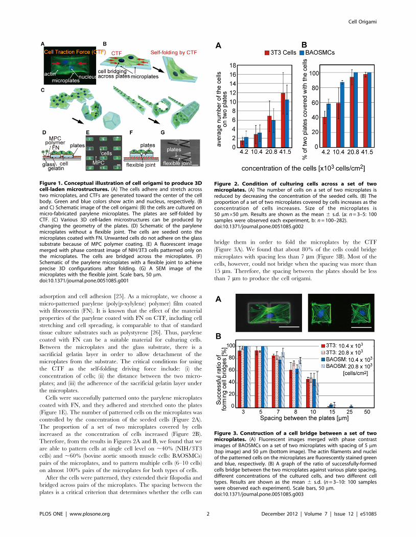
In this research, we harness living cells as the self-folding driving
forces to create diverse range of 3D cell-laden microstructures: this
technique is named cell origami. Cells naturally exert a contractile
force [24], known as the cell traction force (CTF), that is generated
by actomyosin interactions and actin polymerization, and pulls
toward the center of the cell body (Figure 1A). The CTF plays a
vital role in many biological processes including cell migration,
proliferation, and differentiation. Here, we use the CTF to fold 2D
microstructures by patterning cells across a pair of microplates and
detaching the microplates from the glass substrate (Figure 1B). Cell
origami is highly biocompatible and does not require any special
materials for the microplates and hinges to induce folding. In
addition, we can produce various 3D cell-laden microstructures by
just changing the geometrical design of the patterned 2D plates
(Figure 1C).
Results and Discussion
Culturing cells across microplatesWe examined the basic mechanism and design criteria of our
cell origami by culturing cells on a set of two microplates that are
put side by side to form a single folded microstructure. We applied
two types of cell origami: microplates with and without a flexible
joint (Figures 1D and F, Figures S1 and S2). The detail of the
microplate preparation steps is described in the Materials and
Methods section. In both cases, selective patterning of the cells on
the microplates was achieved by coating the glass substrate areas,
where the microplates do not exist, with 2-methacryloyloxyethyl
phosphorylcholine (MPC) polymer; this polymer inhibits protein
PLOS ONE | www.plosone.org 1 December 2012 | Volume 7 | Issue 12 | e51085
adsorption and cell adhesion [25]. As a microplate, we choose a
micro-patterned parylene (poly(p-xylylene) polymer) film coated
with fibronectin (FN). It is known that the effect of the material
properties of the parylene coated with FN on CTF, including cell
stretching and cell spreading, is comparable to that of standard
tissue culture substrates such as polystyrene [26]. Thus, parylene
coated with FN can be a suitable material for culturing cells.
Between the microplates and the glass substrate, there is a
sacrificial gelatin layer in order to allow detachment of the
microplates from the substrate. The critical conditions for using
the CTF as the self-folding driving force include: (i) the
concentration of cells; (ii) the distance between the two micro-
plates; and (iii) the adherence of the sacrificial gelatin layer under
the microplates.
Cells were successfully patterned onto the parylene microplates
coated with FN, and they adhered and stretched onto the plates
(Figure 1E). The number of patterned cells on the microplates was
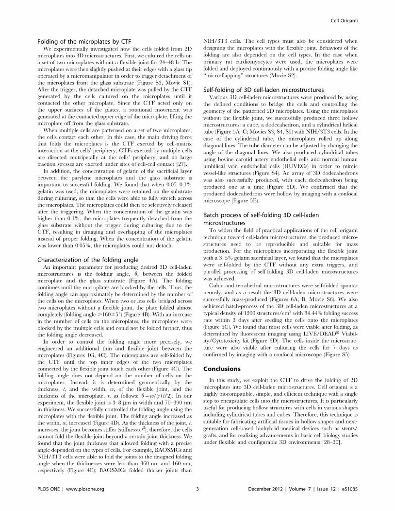
controlled by the concentration of the seeded cells (Figure 2A).
The proportion of a set of two microplates covered by cells
increased as the concentration of cells increased (Figure 2B).
Therefore, from the results in Figures 2A and B, we found that we
are able to pattern cells at single cell level on ,40% (NIH/3T3
cells) and ,60% (bovine aortic smooth muscle cells: BAOSMCs)
pairs of the microplates, and to pattern multiple cells (6–10 cells)
on almost 100% pairs of the microplates for both types of cells.
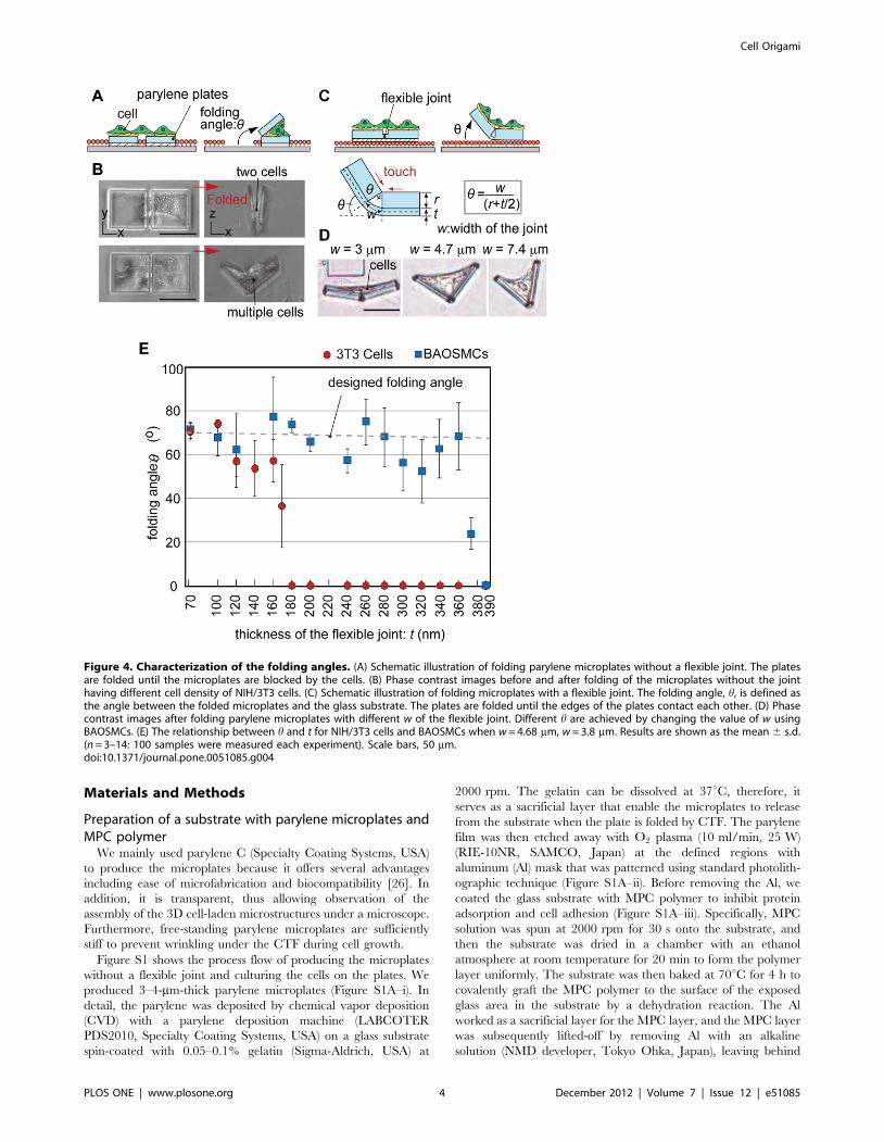
After the cells were patterned, they extended their filopodia and
bridged across pairs of the microplates. The spacing between the
plates is a critical criterion that determines whether the cells can
bridge them in order to fold the microplates by the CTF
(Figure 3A). We found that about 80% of the cells could bridge
microplates with spacing less than 7 mm (Figure 3B). Most of the
cells, however, could not bridge when the spacing was more than
15 mm. Therefore, the spacing between the plates should be less
than 7 mm to produce the cell origami.
Figure 1. Conceptual illustration of cell origami to produce 3Dcell-laden microstructures. (A) The cells adhere and stretch acrosstwo microplates, and CTFs are generated toward the center of the cellbody. Green and blue colors show actin and nucleus, respectively. (Band C) Schematic image of the cell origami: (B) the cells are cultured onmicro-fabricated parylene microplates. The plates are self-folded byCTF. (C) Various 3D cell-laden microstructures can be produced bychanging the geometry of the plates. (D) Schematic of the parylenemicroplates without a flexible joint. The cells are seeded onto themicroplates coated with FN. Unwanted cells do not adhere on the glasssubstrate because of MPC polymer coating. (E) A fluorescent imagemerged with phase contrast image of NIH/3T3 cells patterned only onthe microplates. The cells are bridged across the microplates. (F)Schematic of the parylene microplates with a flexible joint to achieveprecise 3D configurations after folding. (G) A SEM image of themicroplates with the flexible joint. Scale bars, 50 mm.doi:10.1371/journal.pone.0051085.g001
Figure 2. Condition of culturing cells across a set of twomicroplates. (A) The number of cells on a set of two microplates isreduced by decreasing the concentration of the seeded cells. (B) Theproportion of a set of two microplates covered by cells increases as theconcentration of cells increases. Size of the microplates is50 mm650 mm. Results are shown as the mean 6 s.d. (a: n = 3–5: 100samples were observed each experiment, b: n = 100–282).doi:10.1371/journal.pone.0051085.g002
Figure 3. Construction of a cell bridge between a set of twomicroplates. (A) Fluorescent images merged with phase contrastimages of BAOSMCs on a set of two microplates with spacing of 5 mm(top image) and 50 mm (bottom image). The actin filaments and nucleiof the patterned cells on the microplates are fluorescently stained greenand blue, respectively. (B) A graph of the ratio of successfully-formedcells bridge between the two microplates against various plate spacing,different concentrations of the cultured cells, and two different celltypes. Results are shown as the mean 6 s.d. (n = 3–10: 100 sampleswere observed each experiment). Scale bars, 50 mm.doi:10.1371/journal.pone.0051085.g003
Cell Origami
PLOS ONE | www.plosone.org 2 December 2012 | Volume 7 | Issue 12 | e51085
Folding of the microplates by CTFWe experimentally investigated how the cells folded from 2D
microplates into 3D microstructures. First, we cultured the cells on
a set of two microplates without a flexible joint for 24–48 h. The
microplates were then slightly pushed at their edges with a glass tip
operated by a micromanipulator in order to trigger detachment of
the microplates from the glass substrate (Figure S3, Movie S1).
After the trigger, the detached microplate was pulled by the CTF
generated by the cells cultured on the microplates until it
contacted the other microplate. Since the CTF acted only on
the upper surfaces of the plates, a rotational movement was
generated at the contacted upper edge of the microplate, lifting the
microplate off from the glass substrate.
When multiple cells are patterned on a set of two microplates,
the cells contact each other. In this case, the main driving force
that folds the microplates is the CTF exerted by cell-matrix
interaction at the cells’ periphery; CTFs exerted by multiple cells
are directed centripetally at the cells’ periphery, and no large
traction stresses are exerted under sites of cell-cell contact [27].
In addition, the concentration of gelatin of the sacrificial layer
between the parylene microplates and the glass substrate is
important to successful folding. We found that when 0.05–0.1%
gelatin was used, the microplates were retained on the substrate
during culturing, so that the cells were able to fully stretch across
the microplates. The microplates could then be selectively released
after the triggering. When the concentration of the gelatin was
higher than 0.1%, the microplates frequently detached from the
glass substrate without the trigger during culturing due to the
CTF, resulting in dragging and overlapping of the microplates
instead of proper folding. When the concentration of the gelatin
was lower than 0.05%, the microplates could not detach.
Characterization of the folding angleAn important parameter for producing desired 3D cell-laden
microstructures is the folding angle, h, between the folded
microplate and the glass substrate (Figure 4A). The folding
continues until the microplates are blocked by the cells. Thus, the
folding angle can approximately be determined by the number of
the cells on the microplates. When two or less cells bridged across
two microplates without a flexible joint, the plate folded almost
completely (folding angle .16065u) (Figure 4B). With an increase
in the number of cells on the microplates, the microplates were
blocked by the multiple cells and could not be folded further, thus
the folding angle decreased.
In order to control the folding angle more precisely, we
engineered an additional thin and flexible joint between the
microplates (Figures 1G, 4C). The microplates are self-folded by
the CTF until the top inner edges of the two microplates
connected by the flexible joint touch each other (Figure 4C). The
folding angle does not depend on the number of cells on the
microplates. Instead, it is determined geometrically by the
thickness, t, and the width, w, of the flexible joint, and the
thickness of the microplate, r, as follows: h = w/(r+t/2). In our
experiment, the flexible joint is 3–8 mm in width and 70–390 nm
in thickness. We successfully controlled the folding angle using the
microplates with the flexible joint. The folding angle increased as
the width, w, increased (Figure 4D). As the thickness of the joint, t,
increases, the joint becomes stiffer (stiffness/t3), therefore, the cells
cannot fold the flexible joint beyond a certain joint thickness. We
found that the joint thickness that allowed folding with a precise
angle depended on the types of cells. For example, BAOSMCs and
NIH/3T3 cells were able to fold the joints to the designed folding
angle when the thicknesses were less than 360 nm and 160 nm,
respectively (Figure 4E); BAOSMCs folded thicker joints than
NIH/3T3 cells. The cell types must also be considered when
designing the microplates with the flexible joint. Behaviors of the
folding are also depended on the cell types. In the case when
primary rat cardiomyocytes were used, the microplates were
folded and deployed continuously with a precise folding angle like
‘‘micro-flapping’’ structures (Movie S2).
Self-folding of 3D cell-laden microstructuresVarious 3D cell-laden microstructures were produced by using
the defined conditions to bridge the cells and controlling the
geometry of the patterned 2D microplates. Using the microplates
without the flexible joint, we successfully produced three hollow
microstructures: a cube, a dodecahedron, and a cylindrical helical
tube (Figure 5A–C; Movies S3, S4, S5) with NIH/3T3 cells. In the
case of the cylindrical tube, the microplates rolled up along
diagonal lines. The tube diameter can be adjusted by changing the
angle of the diagonal lines. We also produced cylindrical tubes
using bovine carotid artery endothelial cells and normal human
umbilical vein endothelial cells (HUVECs) in order to mimic
vessel-like structures (Figure S4). An array of 3D dodecahedrons
was also successfully produced, with each dodecahedron being
produced one at a time (Figure 5D). We confirmed that the
produced dodecahedrons were hollow by imaging with a confocal
microscope (Figure 5E).
Batch process of self-folding 3D cell-ladenmicrostructures
To widen the field of practical applications of the cell origami
technique toward cell-laden microstructures, the produced micro-
structures need to be reproducible and suitable for mass
production. For the microplates incorporating the flexible joint
with a 3–5% gelatin sacrificial layer, we found that the microplates
were self-folded by the CTF without any extra triggers, and
parallel processing of self-folding 3D cell-laden microstructures
was achieved.
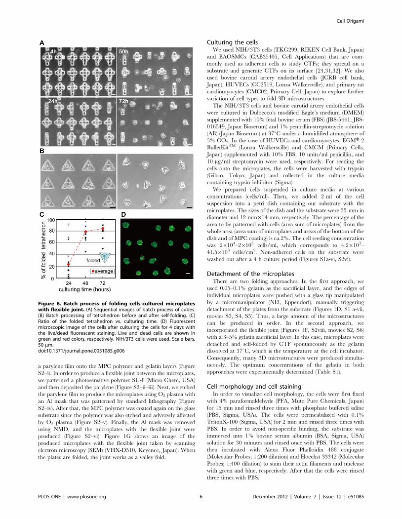
Cubic and tetrahedral microstructures were self-folded sponta-
neously, and as a result the 3D cell-laden microstructures were
successfully mass-produced (Figures 6A, B, Movie S6). We also
achieved batch-process of the 3D cell-laden microstructures at a
typical density of 1200 structures/cm2 with 84.44% folding success
rate within 3 days after seeding the cells onto the microplates
(Figure 6C). We found that most cells were viable after folding, as
determined by fluorescent imaging using LIVE/DEADH Viabil-
ity/Cytotoxicity kit (Figure 6D). The cells inside the microstruc-
ture were also viable after culturing the cells for 7 days as
confirmed by imaging with a confocal microscope (Figure S5).
Conclusions
In this study, we exploit the CTF to drive the folding of 2D
microplates into 3D cell-laden microstructures. Cell origami is a
highly biocompatible, simple, and efficient technique with a single
step to encapsulate cells into the microstructures. It is particularly
useful for producing hollow structures with cells in various shapes
including cylindrical tubes and cubes. Therefore, this technique is
suitable for fabricating artificial tissues in hollow shapes and next-
generation cell-based biohybrid medical devices such as stents/
grafts, and for realizing advancements in basic cell biology studies
under flexible and configurable 3D environments [28–30].
Cell Origami
PLOS ONE | www.plosone.org 3 December 2012 | Volume 7 | Issue 12 | e51085
Materials and Methods
Preparation of a substrate with parylene microplates andMPC polymer
We mainly used parylene C (Specialty Coating Systems, USA)
to produce the microplates because it offers several advantages
including ease of microfabrication and biocompatibility [26]. In
addition, it is transparent, thus allowing observation of the
assembly of the 3D cell-laden microstructures under a microscope.
Furthermore, free-standing parylene microplates are sufficiently
stiff to prevent wrinkling under the CTF during cell growth.
Figure S1 shows the process flow of producing the microplates
without a flexible joint and culturing the cells on the plates. We
produced 3–4-mm-thick parylene microplates (Figure S1A–i). In
detail, the parylene was deposited by chemical vapor deposition
(CVD) with a parylene deposition machine (LABCOTER
PDS2010, Specialty Coating Systems, USA) on a glass substrate
spin-coated with 0.05–0.1% gelatin (Sigma-Aldrich, USA) at
2000 rpm. The gelatin can be dissolved at 37uC, therefore, it
serves as a sacrificial layer that enable the microplates to release
from the substrate when the plate is folded by CTF. The parylene
film was then etched away with O2 plasma (10 ml/min, 25 W)
(RIE-10NR, SAMCO, Japan) at the defined regions with
aluminum (Al) mask that was patterned using standard photolith-
ographic technique (Figure S1A–ii). Before removing the Al, we
coated the glass substrate with MPC polymer to inhibit protein
adsorption and cell adhesion (Figure S1A–iii). Specifically, MPC
solution was spun at 2000 rpm for 30 s onto the substrate, and
then the substrate was dried in a chamber with an ethanol
atmosphere at room temperature for 20 min to form the polymer
layer uniformly. The substrate was then baked at 70uC for 4 h to
covalently graft the MPC polymer to the surface of the exposed
glass area in the substrate by a dehydration reaction. The Al
worked as a sacrificial layer for the MPC layer, and the MPC layer
was subsequently lifted-off by removing Al with an alkaline
solution (NMD developer, Tokyo Ohka, Japan), leaving behind
Figure 4. Characterization of the folding angles. (A) Schematic illustration of folding parylene microplates without a flexible joint. The platesare folded until the microplates are blocked by the cells. (B) Phase contrast images before and after folding of the microplates without the jointhaving different cell density of NIH/3T3 cells. (C) Schematic illustration of folding microplates with a flexible joint. The folding angle, h, is defined asthe angle between the folded microplates and the glass substrate. The plates are folded until the edges of the plates contact each other. (D) Phasecontrast images after folding parylene microplates with different w of the flexible joint. Different h are achieved by changing the value of w usingBAOSMCs. (E) The relationship between h and t for NIH/3T3 cells and BAOSMCs when w = 4.68 mm, w = 3.8 mm. Results are shown as the mean 6 s.d.(n = 3–14: 100 samples were measured each experiment). Scale bars, 50 mm.doi:10.1371/journal.pone.0051085.g004
Cell Origami
PLOS ONE | www.plosone.org 4 December 2012 | Volume 7 | Issue 12 | e51085

bare parylene surface (Figure S1A–iv). Therefore, the cells can
only be seeded onto the patterned parylene plates that are coated
with FN (Funakoshi, Japan) at 10 mg/ml concentration (Figure
S1A–v–vi).
Figure S2 shows the process flow of producing the microplates
with a flexible joint and culturing the cells on the plates. The first
step is forming MPC polymer and gelatin layers on a glass
substrate, so that the cells cannot adhere the substrate after the
folding. 3–5% gelatin solution was spin-coated. We then deposited
Figure 5. Sequential images of various 3D cell-laden microstructures folded by CTF. (A)–(C) Regular tetragon, regular dodecahedron andcylindrical tube were self-folded. (D) A fluorescent image of regular dodecahedrons. (E) A cross-section (a–a9) image of the dodecahedron structure ina hollow shape taken by a confocal scanning laser microscopy. Green and blue colors show actin and nucleus, respectively. NIH/3T3 cells were used.Scale bars, 50 mm.doi:10.1371/journal.pone.0051085.g005
Cell Origami
PLOS ONE | www.plosone.org 5 December 2012 | Volume 7 | Issue 12 | e51085
a parylene film onto the MPC polymer and gelatin layers (Figure
S2–i). In order to produce a flexible joint between the microplates,
we patterned a photosensitive polymer SU-8 (Micro Chem, USA)
and then deposited the parylene (Figure S2–ii–iii). Next, we etched
the parylene film to produce the microplates using O2 plasma with
an Al mask that was patterned by standard lithography (Figure
S2–iv). After that, the MPC polymer was coated again on the glass
substrate since the polymer was also etched and adversely affected
by O2 plasma (Figure S2–v). Finally, the Al mask was removed
using NMD, and the microplates with the flexible joint were
produced (Figure S2–vi). Figure 1G shows an image of the
produced microplates with the flexible joint taken by scanning
electron microscopy (SEM) (VHX-D510, Keyence, Japan). When
the plates are folded, the joint works as a valley fold.
Culturing the cellsWe used NIH/3T3 cells (TKG299, RIKEN Cell Bank, Japan)
and BAOSMCs (CAB35405, Cell Applications) that are com-
monly used as adherent cells to study CTFs; they spread on a
substrate and generate CTFs on its surface [24,31,32]. We also
used bovine carotid artery endothelial cells (JCRB cell bank,
Japan), HUVECs (CC2519, Lonza Walkersville), and primary rat
cardiomyocytes (CMC02, Primary Cell, Japan) to explore further
variation of cell types to fold 3D microstructures.
The NIH/3T3 cells and bovine carotid artery endothelial cells
were cultured in Dulbecco’s modified Eagle’s medium (DMEM)
supplemented with 10% fetal bovine serum (FBS) (JBS-5441, JBS-
016549, Japan Bioserum) and 1% penicillin-streptomycin solution
(AB) (Japan Bioserum) at 37uC under a humidified atmosphere of
5% CO2. In the case of HUVECs and cardiomyocytes, EGMH-2
BulletKitTM (Lonza Walkersville) and CMCM (Primary Cells,
Japan) supplemented with 10% FBS, 10 units/ml penicillin, and
10 mg/ml streptomycin were used, respectively. For seeding the
cells onto the microplates, the cells were harvested with trypsin
(Gibco, Tokyo, Japan) and collected in the culture media
containing trypsin inhibitor (Sigma).
We prepared cells suspended in culture media at various
concentrations (cells/ml). Then, we added 2 ml of the cell
suspension into a petri dish containing our substrate with the
microplates. The sizes of the dish and the substrate were 35 mm in
diameter and 12 mm614 mm, respectively. The percentage of the
area to be patterned with cells (area sum of microplates) from the
whole area (area sum of microplates and areas of the bottom of the
dish and of MPC coating) is ca.2%. The cell seeding concentration
was 26104–26105 cells/ml, which corresponds to 4.26103–
41.56103 cells/cm2. Non-adhered cells on the substrate were
washed out after a 4 h culture period (Figures S1a-vi, S2vi).
Detachment of the microplatesThere are two folding approaches. In the first approach, we
used 0.05–0.1% gelatin as the sacrificial layer, and the edges of
individual microplates were pushed with a glass tip manipulated
by a micromanipulator (NI2, Eppendorf), manually triggering
detachment of the plates from the substrate (Figures 1D, S1 a-vii,
movies S3, S4, S5). Thus, a large amount of the microstructures
can be produced in order. In the second approach, we
incorporated the flexible joint (Figures 1F, S2viii, movies S2, S6)
with a 3–5% gelatin sacrificial layer. In this case, microplates were
detached and self-folded by CTF spontaneously as the gelatin
dissolved at 37uC, which is the temperature at the cell incubator.
Consequently, many 3D microstructures were produced simulta-
neously. The optimum concentrations of the gelatin in both
approaches were experimentally determined (Table S1).
Cell morphology and cell stainingIn order to visualize cell morphology, the cells were first fixed
with 4% paraformaldehyde (PFA, Muto Pure Chemicals, Japan)
for 15 min and rinsed three times with phosphate buffered saline
(PBS, Sigma, USA). The cells were permeabilized with 0.1%
TritonX-100 (Sigma, USA) for 2 min and rinsed three times with
PBS. In order to avoid non-specific binding, the substrate was
immersed into 1% bovine serum albumin (BSA, Sigma, USA)
solution for 30 minutes and rinsed once with PBS. The cells were
then incubated with Alexa Fluor Phalloidin 488 conjugate
(Molecular Probes; 1:200 dilution) and Hoechst 33342 (Molecular
Probes; 1:400 dilution) to stain their actin filaments and nuclease
with green and blue, respectively. After that the cells were rinsed
three times with PBS.
Figure 6. Batch process of folding cells-cultured microplateswith flexible joint. (A) Sequential images of batch process of cubes.(B) Batch processing of tetrahedron before and after self-folding. (C)Ratio of the folded tetrahedron vs. culturing time. (D) Fluorescentmicroscopic image of the cells after culturing the cells for 4 days withthe live/dead fluorescent staining. Live and dead cells are shown ingreen and red colors, respectively. NIH/3T3 cells were used. Scale bars,50 mm.doi:10.1371/journal.pone.0051085.g006
Cell Origami
PLOS ONE | www.plosone.org 6 December 2012 | Volume 7 | Issue 12 | e51085
We used the fluorescent imaging kit LIVE/DEADH Viability/
Cytotoxicity to determine cell viability (Invitrogen, USA). The
staining was performed in accordance with the manufacturer’s
instructions. The cells were stained just before the image
acquisition when microplates have already been folded. All
processes were performed at room temperature.
Imaging equipmentThe morphology of the cultured cells on the microplates was
observed using an inverted optical microscope with phase contrast
(IX71, Olympus, Japan). The images (Figures 4B, D) were
captured using a CCD camera (DP72, Olympus, Japan) with an
image software (AioVision, Olympus, Japan). Time-lapse images
of the self-folding process by CTF with phase contrast were
captured with CCD cameras (QICAM, Roper, US) (Figures 5A–
C) or (AxioCam HRc, Carl Zeiss, Germany) (Figures 6A, B). To
observe the fluorescence images of actin filaments and nucleases,
we used an inverted optical fluorescence microscope with CCD
camera and imaging software (BZ-9000, Keyence, Japan). The z-
stack images of the cell origami (Figure 5E) were taken by a
confocal laser scanning microscope (Fluoview FV1000, Olympus,
Japan).
Supporting Information
Movie S1 Time-lapse images of self-folding microstructures with
cells across a pair of the microplates by CTF.
(MOV)
Movie S2 Time-lapse images of continuously folding and
deploying plates with a flexible joint driven by the cardiomy-ocytes cultured on the plates.
(MOV)
Movie S3 Time-lapse images of self-folding 3D cell-laden
structure by CTF: cube.
(MOV)
Movie S4 Time-lapse images of self-folding 3D cell-laden
structure by CTF: dodecahedron.
(MOV)
Movie S5 Time-lapse images of self-folding 3D cell-laden
structure by CTF: cylindrical helical tube.
(MOV)
Movie S6 Time-lapse images of batch process of self-folding 3D cell-laden.
(MOV)
Figure S1 Schematic illustration of the fabrication stepsof self-folding using the microplates. (A) (i)–(ii) Parylene
microplates were produced by using standard photolithography.
(iii)–(iv) MPC polymer was coated to prevent cells from adhering
the areas without the microplates. (v)– (vii) Cells were cultured
onto the microplates coated with FN, and the plates were self-
folded by CTF when trigger was applied (Figures 4B and 5 in main
text). (B) Culturing the cells onto substrates coated with and
without MPC polymer.
(TIF)
Figure S2 Schematic illustration of the fabrication stepsof self-folding using the microplates with a flexible joint.(i)–(iv) The microplates with the flexible joint were produced with
parylene and SU-8 by using standard photolithography. (v)–(vi)
MPC polymer was coated to prevent cells from adhering the areas
without the microplates. (vii) Cells were cultured onto the
microplates, and (viii) the plates were self-folded by CTF
spontaneously (Figures 4D and 6 in main text).
(TIF)
Figure S3 Self-folding mechanism. The CTFs were in
equilibrium between a set of two microplates before detaching the
plates from the glass substrate. We then pushed the plates using a
glass tip, triggering detachment of the plates from the substrate.
The cells pulled the upper faces of the detached plates by the
CTFs, dragging the plates towards one another until their edges
contact. Although the edges were pushing each other, the CTFs
acted only on the upper surfaces of the plates, generating a
rotational movement along the contacted upper edge. Conse-
quently, the plates lifted out from the glass substrate and self-folded
(Movie S1).
(TIF)
Figure S4 Images of cylindrical tubes with (A) bovine
carotid artery endothelial cells and (B) HUVECs as vessel-like
structures. Scale bars, 50 mm.
(TIF)
Figure S5 Cross-section images of cells inside themicrostructures after culturing the cells for 7 days.The images of the cells inside the (A) cube and (B) dodecahedron
at top (t), middle (m), and bottom (b) taken by a confocal scanning
laser microscopy. Live and dead cells are shown in green and red
colors, respectively. Scale bars, 50 mm.
(TIF)
Table S1 Concentrations of gelatin for folding micro-plates with and without a flexible joint.(TIF)
Acknowledgments
We gratefully acknowledge Kazuhiko Ishihara at The University of Tokyo
for providing the MPC polymer. We thank Makiko Onuki for parylene
processes and Michiru Sato, Atsuko Sunose and Reiko Yusa at the
University of Tokyo for assistance in the maintenance of cell lines. We also
thank Amy Hsiao, Daniela Serien and Ken’ichi Kawaguchi at the
University of Tokyo for useful comments on the manuscript.
Author Contributions
Conceived and designed the experiments: KKS ST. Performed the
experiments: KKS HO. Analyzed the data: KKS HO ST. Contributed
reagents/materials/analysis tools: KKS HO ST. Wrote the paper: KKS
ST.
References
1. Miura K (1993) Concepts of Deployable Space Structures. Int J Space Struct 8:
3–16.
2. Guest SD, Pellegrino S (1996) The folding of triangulated cylinders .3.
Experiments. J Appl Mech 63: 77–83.
3. Kuribayashi K, Tsuchiya K, You Z, Tomus D, Umemoto M, et al. (2006) Self-
deployable origami stent grafts as a biomedical application of Ni-rich TiNi shape
memory alloy foil. Mater Sci Eng A 419: 131–137.
4. Rothemund PWK (2006) Folding DNA to create nanoscale shapes and patterns.
Nature 440: 297–302.
5. Han DR, Pal S, Nangreave J, Deng ZT, Liu Y, et al. (2011) DNA Origami with
Complex Curvatures in Three-Dimensional Space. Science 332: 342–346.
6. Stewart I (2007) Mathematics - Some assembly needed. Nature 448: 419–419.
7. Merali Z (2011) PROFILE: ZHONG YOU ‘Origami Engineer’ Flexes to Create
Stronger, More Agile Materials. Science 332: 1376–1377.
8. Brittain ST, Schueller OJA, Wu HK, Whitesides S, Whitesides GM (2001)
Microorigami: Fabrication of small, three-dimensional, metallic structures. J Phys
Chem B 105: 347–350.
Cell Origami
PLOS ONE | www.plosone.org 7 December 2012 | Volume 7 | Issue 12 | e51085

9. Ahn BY, Shoji D, Hansen CJ, Hong E, Dunand DC, et al. (2010) Printed
Origami Structures. Adv Mater 22: 2251–2254.10. Suzuki K, Shimoyama I, Miura H (1994) Insect-model based microrobot with
elastic hinges. J Microelectromech Syst 3: 4–9.
11. Iwase E, Shimoyama I (2006) A design method for out-of-plane structures bymulti-step magnetic self-assembly. Sens Actuators, A 127: 310–315.
12. Jamal M, Zarafshar AM, Gracias DH (2011) Differentially photo-crosslinkedpolymers enable self-assembling microfluidics. Nat Commun 2: 1–6.
13. Leong TG, Zarafshar AM, Gracias DH (2010) Three-Dimensional Fabrication
at Small Size Scales. Small 6: 792–806.14. Green PW, Syms RRA, Yeatman EM (1995) Demonstration of three-
dimensional microstructure self-assembly. J Microelectromech Syst 4: 170–176.15. Gimi B, Leong T, Gu ZY, Yang M, Artemov D, et al. (2005) Self-assembled
three dimensional radio frequency (RF) shielded containers for cell encapsula-tion. Biomed Microdevices 7: 341–345.
16. Leong TG, Randall CL, Benson BR, Zarafshar AM, Gracias DH (2008) Self-
loading lithographically structured microcontainers: 3D patterned, mobilemicrowells. Lab Chip 8: 1621–1624.
17. Azam A, Laflin KE, Jamal M, Fernandes R, Gracias DH (2011) Self-foldingmicropatterned polymeric containers. Biomed Microdevices 13: 51–58.
18. Zakharchenko S, Puretskiy N, Stoychev G, Stamm M, Ionov L (2010)
Temperature controlled encapsulation and release using partially biodegradablethermo-magneto-sensitive self-rolling tubes. Soft Matter 6: 2633–2636.
19. Ionov L (2011) Soft microorigami: self-folding polymer films. Soft Matter 7:6786–6791.
20. Jager EWH, Smela E, Inganas O (2000) Microfabricating conjugated polymeractuators. Science 290: 1540–1545.
21. Randall CL, Kalinin YV, Jamal M, Shah A, Gracias DH (2011) Self-folding
immunoprotective cell encapsulation devices. Nanomed-Nanotechnol 7: 686–689.
22. Bassik N, Stern GM, Jamal M, Gracias DH (2008) Patterning Thin Film
Mechanical Properties to Drive Assembly of Complex 3D Structures. Adv Mater20: 4760–4764.
23. Jamal M, Bassik N, Cho JH, Randall CL, Gracias DH (2010) Directed growth of
fibroblasts into three dimensional micropatterned geometries via self-assemblingscaffolds. Biomaterials 31: 1683–1690.
24. Tan JL, Tien J, Pirone DM, Gray DS, Bhadriraju K, et al. (2003) Cells lying ona bed of microneedles: An approach to isolate mechanical force. Proc Natl Acad
Sci U S A 100: 1484–1489.
25. Ishihara K, Iwasaki Y, Ebihara S, Shindo Y, Nakabayashi N (2000)Photoinduced graft polymerization of 2-methacryloyloxyethyl phosphorylcho-
line on polyethylene membrane surface for obtaining blood cell adhesionresistance. Colloids Surf, B 18: 325–335.
26. Chang TY, Yadav VG, De Leo S, Mohedas A, Rajalingam B, et al. (2007) Celland protein compatibility of parylene-C surfaces. Langmuir 23: 11718–11725.
27. Maruthamuthu V, Sabass B, Schwarz US, Gardel ML (2011) Cell-ECM traction
force modulates endogenous tension at cell-cell contacts. Proc Natl AcadSci U S A 108: 4708–4713.
28. Taylor R, Norman JJ, Simmons C, Abilez O, Zarins CK, et al. (2009) Nano andthe future of endovascular medicine. Endovasular Today I: 27–31.
29. Khademhosseini A, Vacanti JP, Langer R (2009) Progress in Tissue Engineering.
Sci Am 300: 64–71.30. Randall CL, Gultepe E, Gracias DH (2012) Self-folding materials and devices
for biomedical applications. Trends Biotechnol 30: 138–146.31. Nagayama K, Matsumoto T (2011) Dynamic Change in Morphology and
Traction Forces at Focal Adhesions in Cultured Vascular Smooth Muscle CellsDuring Contraction. Cell Mol Bioeng 4: 348–357.
32. Ohashi T, Kameda N, Nakamura S, Sato M (2010) Biomechanical Contribution
of Cytoskeletal Structures to Traction Forces in Cultured Smooth Muscle Cells.J Bio Sci Eng 5(3): 262–271.
Cell Origami
PLOS ONE | www.plosone.org 8 December 2012 | Volume 7 | Issue 12 | e51085


