

CFX 5.7
Catalytic Converter Simulation
Workshop 11
ANSYS CFX 5.7

Workshop
CFX v5.7
October 1, 2004Inventory #002157
WS11-2© 2004 ANSYS, Inc. CFX 5.7
Introduction
The catalyst material in the center region is a honeycomb structure upon which reactions
take place
The honeycomb structure is too small to resolve in mesh; it is modeled with a flow
resistance instead.
Focus: use of CFX to set up a flow simulation in ANSYS Workbench (this workshop is based
on imported meshes; second focuses on CFX-Mesh)
Note: this is preview version!!!
Steps:
Preprocess in CFX-Pre, solve in CFX-Solver, and post-process in CFX-Post
Workshop
CFX v5.7
October 1, 2004Inventory #002157
WS11-3© 2004 ANSYS, Inc. CFX 5.7
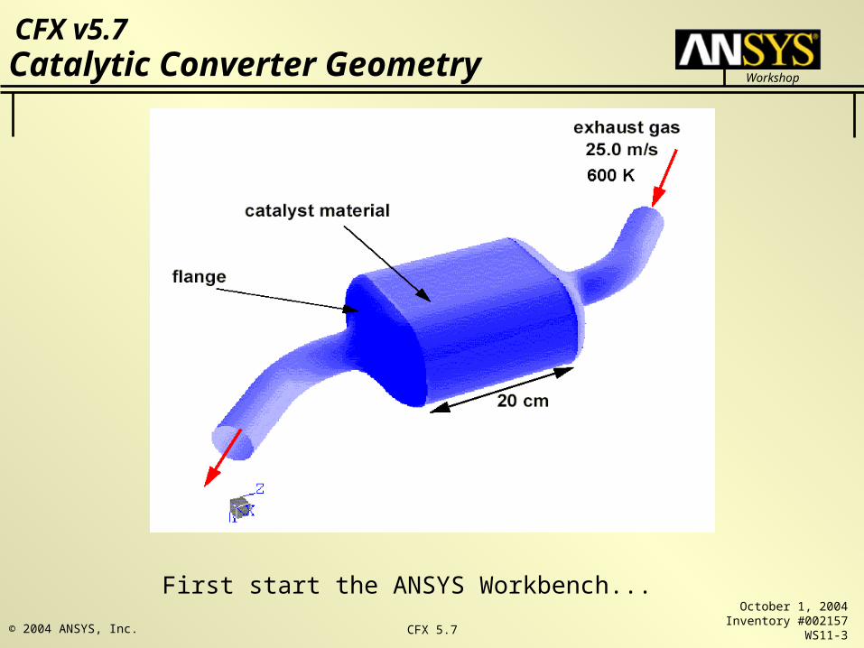
Catalytic Converter Geometry
First start the ANSYS Workbench...

Workshop
CFX v5.7
October 1, 2004Inventory #002157
WS11-4© 2004 ANSYS, Inc. CFX 5.7
Starting the CFX in Workbench
Common starting point for
all ANSYS software
New Project – save
explicitly to start!
Select New Simulation
Advanced CFD tab will
open
Workshop
CFX v5.7
October 1, 2004Inventory #002157
WS11-5© 2004 ANSYS, Inc. CFX 5.7
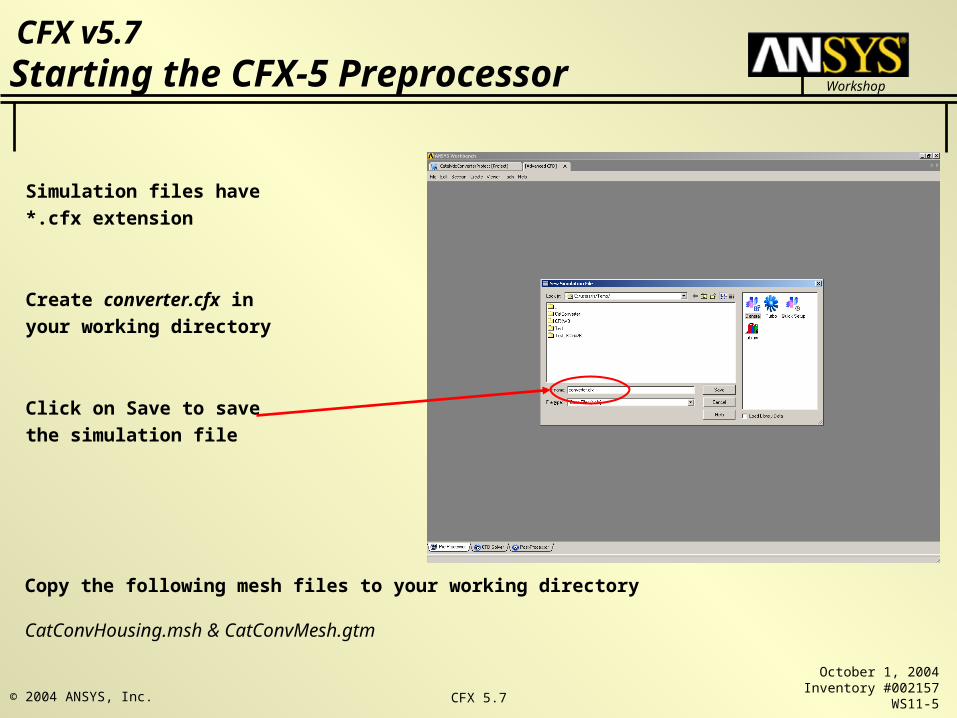
Starting the CFX-5 Preprocessor
Simulation files have *.cfx
extension
Create converter.cfx in your
working directory
Click on Save to save the
simulation file
Copy the following mesh files to your working directory
CatConvHousing.msh & CatConvMesh.gtm

Workshop
CFX v5.7
October 1, 2004Inventory #002157
WS11-6© 2004 ANSYS, Inc. CFX 5.7
Importing the Hex Mesh
You will first import a mesh for
the central catalyst section
(right mouse click)
The hex mesh was created in
ICEM CFD Hex
Set the mesh format to ICEM
CFD and browse to your
working directory
Select CatConvHousing.msh,
set the mesh units to cm, and
click OK to import the mesh

Workshop
CFX v5.7
October 1, 2004Inventory #002157
WS11-7© 2004 ANSYS, Inc. CFX 5.7
Importing the Hex Mesh
Workshop
CFX v5.7
October 1, 2004Inventory #002157
WS11-8© 2004 ANSYS, Inc. CFX 5.7
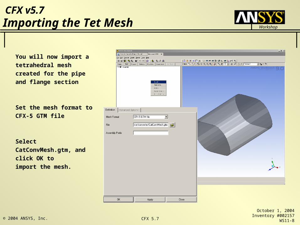
You will now import a
tetrahedral mesh created for
the pipe and flange section
Set the mesh format to CFX-
5 GTM file
Select CatConvMesh.gtm,
and click OK to
import the mesh.
Importing the Tet Mesh

Workshop
CFX v5.7
October 1, 2004Inventory #002157
WS11-9© 2004 ANSYS, Inc. CFX 5.7
Transforming a Mesh Assembly
The second end section is identical to the
first except that it has been rotated by 180
degrees about the center of the housing
You will copy and rotate the flange section
you imported by 180 degrees about an axis
parallel to the y-axis located at the center
of the catalyst housing
In the Mesh Workspace, select Mesh
Assembly 2 and right-mouse click to
Transform…
This brings up the Mesh Transformation
Editor
Ensure that the CFX-Pre working units are
set to SI System.
(Edit>Options>Common>Units)

Workshop
CFX v5.7
October 1, 2004Inventory #002157
WS11-10© 2004 ANSYS, Inc. CFX 5.7
Mesh Transformation Editor
Set the Transformation to Rotation and set
Method to Rotation Axis
In the From boxes enter (0, 0, 0.16)
In the To boxes enter (0, 1, 0.16)
Under Angle, set the Option to Specified and
Angle to 180 degrees
In order to prevent the transformed mesh from
being deleted, enable the Multiple Copies
toggle. Click OK to transform the mesh

Workshop
CFX v5.7
October 1, 2004Inventory #002157
WS11-11© 2004 ANSYS, Inc. CFX 5.7
Completed Transformation
Transformed Mesh
Original Mesh
Workshop
CFX v5.7
October 1, 2004Inventory #002157
WS11-12© 2004 ANSYS, Inc. CFX 5.7
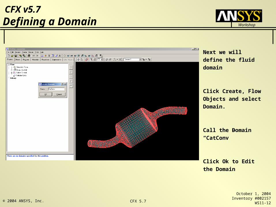
Defining a Domain
Next we will define the
fluid domain
Click Create, Flow
Objects and select
Domain.
Call the Domain
“CatConv”
Click Ok to Edit the
Domain

Workshop
CFX v5.7
October 1, 2004Inventory #002157
WS11-13© 2004 ANSYS, Inc. CFX 5.7
Defining a Domain
On the General Options Panel on the Domain form:
Click in the Location box and hold the <CTRL> key
down and select all three mesh assemblies
(Assembly, Assembly 2, Assembly 3)
Set the Fluids List to Air Ideal Gas
Set the Reference Pressure to 1 atm
On the Fluid Models tab:
Set the Heat Transfer Model Option to Isothermal
and set the Fluid Temperature to 600 K.
Leave all other values at their default and click OK
to apply the form

Workshop
CFX v5.7
October 1, 2004Inventory #002157
WS11-14© 2004 ANSYS, Inc. CFX 5.7
Defining a Subdomain
The catalyst-coated honeycomb structure will
be modeled using a subdomain with a
directional source of resistance.
For quadratic resistances, the pressure drop is
modeled as:
To create a subdomain, click on the Subdomain
icon from the main toolbar
Set the Name to Catalyst and click OK.
On the Basic Settings Panel, set the Location to
Assembly and then click the Sources tab

Workshop
CFX v5.7
October 1, 2004Inventory #002157
WS11-15© 2004 ANSYS, Inc. CFX 5.7
Setting a Quadratic Resistance
On the Sources panel:
Turn on Sources, Momentum Source/Porous Loss, and Directional Loss Model
Under Streamwise Direction, set the Option to Cartesian Components and set:
X Component to 0
Y Component to 0
Z Component to 1
Under Streamwise Loss, set the Option to Linear and Quadratic Coefs
Turn on Quadratic Coefficient and enter a value of 650 kg/m^4
Click OK to create the subdomain
To create a subdomain, click on the Subdomain icon from the main toolbar
Set the Name to Catalyst and click OK.
On the Basic Settings Panel, set the Location to Assembly and then click the Sources
tab

Workshop
CFX v5.7
October 1, 2004Inventory #002157
WS11-16© 2004 ANSYS, Inc. CFX 5.7
Inlet Boundary
Next, we will create inlet and outlet
boundary conditions to the fluid domain
Create a boundary condition called “inlet”
Set the Boundary type to Inlet and the
location to PipeEnd 2.
On the Boundary Details panel, set the
Option to Normal Speed and set a value of
25 m/s. Apply the form.

Workshop
CFX v5.7
October 1, 2004Inventory #002157
WS11-17© 2004 ANSYS, Inc. CFX 5.7
Outlet Boundary
Create a boundary condition called “outlet”
Set the Boundary type to Outlet and the
location to PipeEnd.
On the Boundary Details panel, set the
Option to Static Pressure (not Average Static
Pressure) and Relative Pressure to 0 Pa.
Apply the form.

Workshop
CFX v5.7
October 1, 2004Inventory #002157
WS11-18© 2004 ANSYS, Inc. CFX 5.7
Boundary Conditions

Workshop
CFX v5.7
October 1, 2004Inventory #002157
WS11-19© 2004 ANSYS, Inc. CFX 5.7
Domain Interfaces
Domain interfaces are also used to join dissimilar
meshes together. You will need to create GGI
interfaces between the inlet pipe section mesh and
the catalyst housing and between the catalyst
housing and the outlet pipe section
Click on the Domain Interfaces icon
and set the name to InletSide
On the Basic Settings panel, set the Interface Type to
Fluid Fluid.
Set the Side 1 Filter to All Domains and select
FlangeEnd 2 in Region List 2
Set the Side 2 Filter to All Domains and select INLET in
Region List 1 Click Ok to apply the form.
Workshop
CFX v5.7
October 1, 2004Inventory #002157
WS11-20© 2004 ANSYS, Inc. CFX 5.7
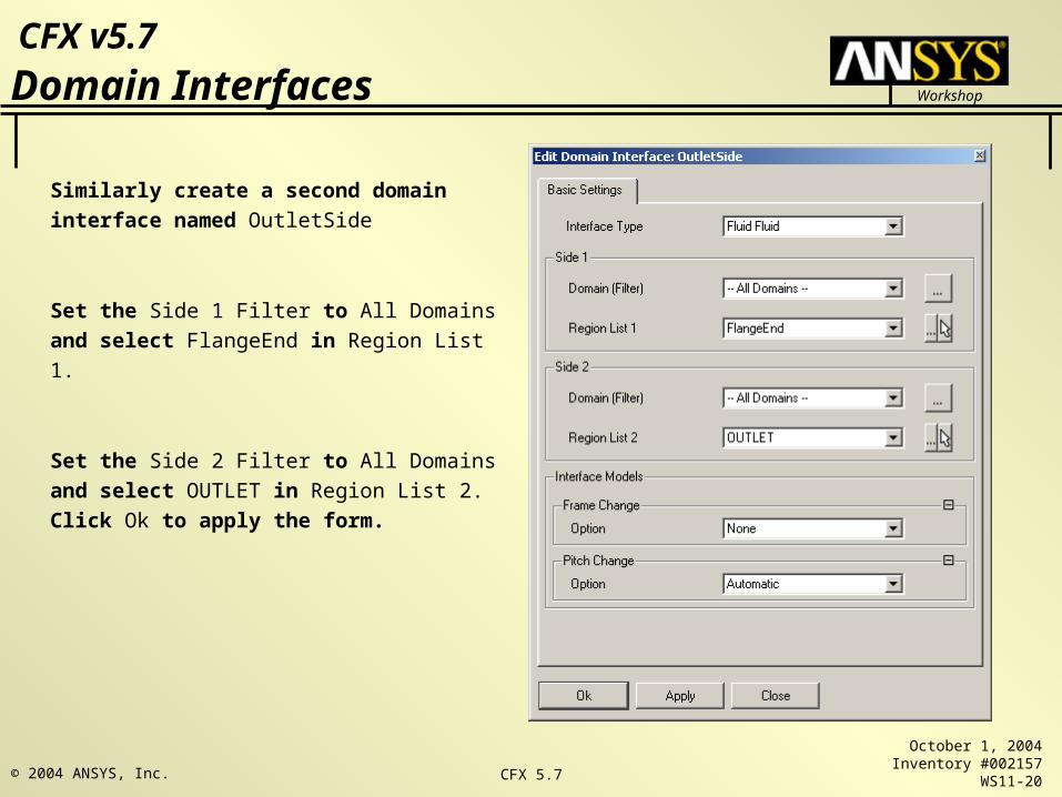
Domain Interfaces
Similarly create a second domain interface
named OutletSide
Set the Side 1 Filter to All Domains and select
FlangeEnd in Region List 1.
Set the Side 2 Filter to All Domains and select
OUTLET in Region List 2. Click Ok to apply
the form.

Workshop
CFX v5.7
October 1, 2004Inventory #002157
WS11-21© 2004 ANSYS, Inc. CFX 5.7
Domain Interfaces
Workshop
CFX v5.7
October 1, 2004Inventory #002157
WS11-22© 2004 ANSYS, Inc. CFX 5.7
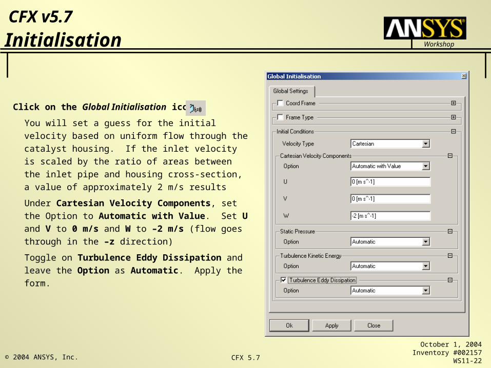
Initialisation
Click on the Global Initialisation icon
You will set a guess for the initial velocity based on
uniform flow through the catalyst housing. If the
inlet velocity is scaled by the ratio of areas between
the inlet pipe and housing cross-section, a value of
approximately 2 m/s results
Under Cartesian Velocity Components, set the
Option to Automatic with Value. Set U and V to 0
m/s and W to –2 m/s (flow goes through in the –z
direction)
Toggle on Turbulence Eddy Dissipation and leave
the Option as Automatic. Apply the form.
Workshop
CFX v5.7
October 1, 2004Inventory #002157
WS11-23© 2004 ANSYS, Inc. CFX 5.7
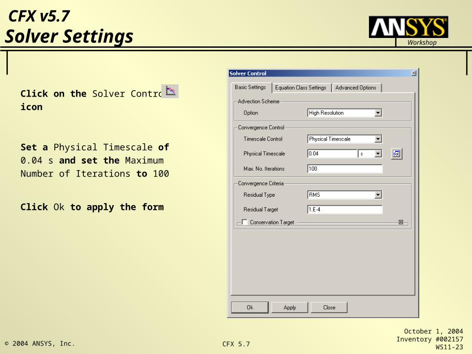
Solver Settings
Click on the Solver Control icon
Set a Physical Timescale of 0.04 s and
set the Maximum Number of Iterations
to 100
Click Ok to apply the form

Workshop
CFX v5.7
October 1, 2004Inventory #002157
WS11-24© 2004 ANSYS, Inc. CFX 5.7
Select the Write a Solver File icon
Set File Name to converter.def.
Set Operation to Start Solver Manager.
Turn on report Summary of Interface
Connections
Press OK
A report of the GGI interfaces you created will be
displayed. Click OK in the information window.
Exit Pre and Click Yes on Save Changes window to
save the cfx file
Writing a Definition File

Workshop
CFX v5.7
October 1, 2004Inventory #002157
WS11-25© 2004 ANSYS, Inc. CFX 5.7
Defining the Run
When the Define Run form
comes up click the Start Run
button to start the run.

Workshop
CFX v5.7
October 1, 2004Inventory #002157
WS11-26© 2004 ANSYS, Inc. CFX 5.7
Monitoring Convergence

Workshop
CFX v5.7
October 1, 2004Inventory #002157
WS11-27© 2004 ANSYS, Inc. CFX 5.7
Launching CFX POST
Click on ‘Post Process’ icon
Choose to shut down the Solver
Manager and click OK to launch
CFX – Post with the current
results file

Workshop
CFX v5.7
October 1, 2004Inventory #002157
WS11-28© 2004 ANSYS, Inc. CFX 5.7
Viewing the Domain Interfaces
Turn off visibility of the
Wireframe.
Make InletSide Side CatConv
Part 1 visible and double-
click it in the list.
Workshop
CFX v5.7
October 1, 2004Inventory #002157
WS11-29© 2004 ANSYS, Inc. CFX 5.7
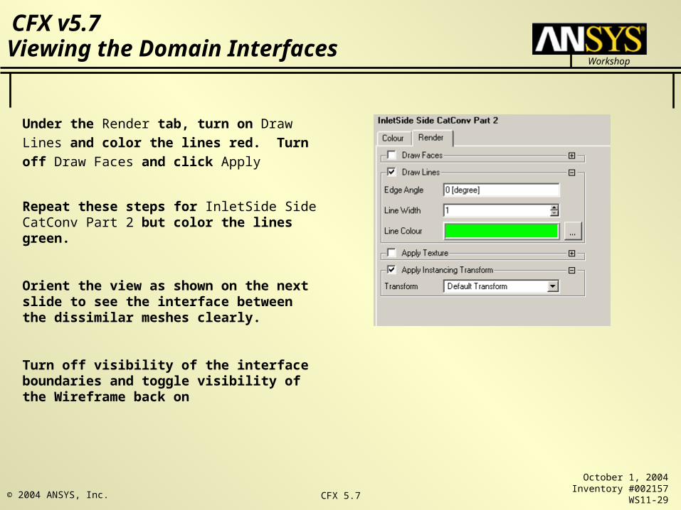
Viewing the Domain Interfaces
Under the Render tab, turn on Draw Lines and
color the lines red. Turn off Draw Faces and
click Apply
Repeat these steps for InletSide Side CatConv Part 2 but color the lines green.
Orient the view as shown on the next slide to see the interface between the dissimilar meshes clearly.
Turn off visibility of the interface boundaries and toggle visibility of the Wireframe back on

Workshop
CFX v5.7
October 1, 2004Inventory #002157
WS11-30© 2004 ANSYS, Inc. CFX 5.7
Viewing the Domain Interfaces

Workshop
CFX v5.7
October 1, 2004Inventory #002157
WS11-31© 2004 ANSYS, Inc. CFX 5.7
Click on the Create Plane icon in the main tool bar
Create a ZX plane through Y = 0 and color the plane
according to Pressure. You can see the pressure falls
steadily through the housing.
Make the plane invisible and create a vector plot on it.
The flow through the housing is uniform as expected
although there is some separation where the inlet pipe
expands into the flange.
Creating a Slice Plane

Workshop
CFX v5.7
October 1, 2004Inventory #002157
WS11-32© 2004 ANSYS, Inc. CFX 5.7
Creating a Polyline
Make the vector plot invisible
You will create a polyline to plot the pressure as a
function of the z coordinate.
Click on the polyline icon from the main toolbar
and accept the default name. On the form, set the
Method to Boundary Intersection.
Set the Boundary List to CatConv default, inlet and outlet
(hold the <CTRL> down for multiple select)
Set Intersect With to Plane 1
Click on the Color tab and choose a bright color for
the polyline. Click on the Render tab and increase the
Line Width to 3. Apply the form.

Workshop
CFX v5.7
October 1, 2004Inventory #002157
WS11-33© 2004 ANSYS, Inc. CFX 5.7
Creating a Chart
You will create a chart to plot the pressure as a function of the z coordinate on the polyline you just created.
Click on the chart icon from the main toolbar and accept the default name.
Set the X Axis to Z and the Y Axis to Pressure
Click Apply.
You can see that the pressure drops linearly through the main body of the housing due to the resistance of the catalyst.

Workshop
CFX v5.7
October 1, 2004Inventory #002157
WS11-34© 2004 ANSYS, Inc. CFX 5.7
Exporting Data
From the Main Menu select File/Export.
Make sure that Export Geometry Information is
toggled on. This will cause X, Y, and Z values to
be sent to the output file. The connectivity
information could be used to create a file that you
could read back in as a polyline.
Select Pressure in the Select Variable(s) list.
Click the Formatting tab and set the Precision to 3.
Click Save to export the results. The file
export.csv will be written to the current working
directory. You can view this file in any text editor.


