

C-2
Source-changeover system without automatic-control systemWithout auxiliaries for emergency off Local reset
Db401805.e
ps
Db101659.e
ps
Voluntary remote reset
Db101660.e
ps
Automatic reset
(1)
LegendsQN “Normal” source Compact NSX equipped with motor mechanismQR “Replacement” source Compact NSX equipped with motor
mechanismSDE “fault-trip” indication contactIVE electrical interlocking and terminal block unitMT motor mechanismOF2 breaker ON/OFF indication contactRN reset order for breaker QNRR reset order for breaker QR
States permitted by mechanical interlocking system
Normal Replacement
0 0
1 0
0 1
Note: diagram shown with circuits de-energised, circuit breakers open and relays in normal position.
Remote-operated source-changeover systems2 Compact NSX100/630 devicesDiagram no. 51201177
Electrical diagrams
313E.indb 2 09/04/2013 13:04:52
C-3
Electrical diagrams
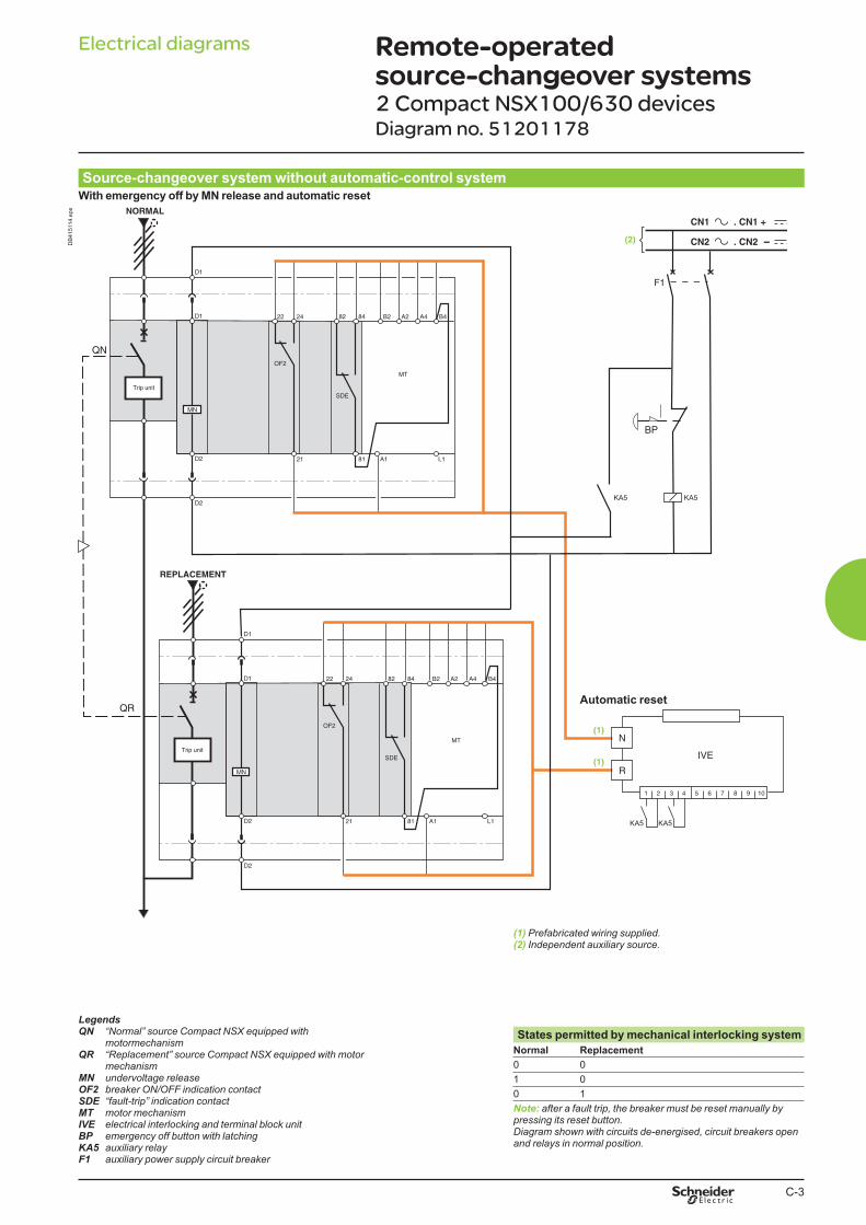
Source-changeover system without automatic-control systemWith emergency off by MN release and automatic reset
KA5 KA5
KA5KA5
DB
415114.e
ps
Automatic reset
(1) Prefabricated wiring supplied.(2) Independent auxiliary source.
LegendsQN “Normal” source Compact NSX equipped with
motormechanismQR “Replacement” source Compact NSX equipped with motor
mechanismMN undervoltage releaseOF2 breaker ON/OFF indication contactSDE “fault-trip” indication contactMT motor mechanismIVE electrical interlocking and terminal block unitBP emergency off button with latchingKA5 auxiliary relayF1 auxiliary power supply circuit breaker
States permitted by mechanical interlocking system
Normal Replacement
0 0
1 0
0 1
Note: after a fault trip, the breaker must be reset manually by pressing its reset button.Diagram shown with circuits de-energised, circuit breakers open and relays in normal position.
Remote-operated source-changeover systems 2 Compact NSX100/630 devicesDiagram no. 51201178
313E.indb 3 09/04/2013 13:04:53
C-4
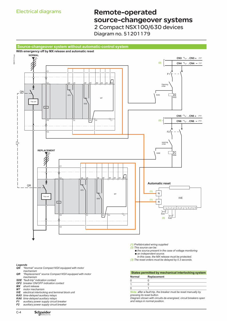
Source-changeover system without automatic-control systemWith emergency off by MX release and automatic reset
DB
415115.e
ps
Automatic reset
(1) Prefabricated wiring supplied(2) This source can be:
b the source present in the case of voltage monitoringb an independent source.
In this case, the MX release must be protected.(3) The reset orders must be delayed by 0.3 seconds.
LegendsQN “Normal” source Compact NSX equipped with motor
mechanismQR “Replacement” source Compact NSX equipped with motor
mechanismSDE “fault-trip” indication contactOF2 breaker ON/OFF indication contactMX shunt releaseMT motor mechanismIVE electrical interlocking and terminal block unitKA5 time-delayed auxiliary relaysKA6 time-delayed auxiliary relaysF1 auxiliary power supply circuit breakerF2 auxiliary power supply circuit breaker
States permitted by mechanical interlocking system
Normal Replacement
0 0
1 0
0 1
Note: after a fault trip, the breaker must be reset manually by pressing its reset button.Diagram shown with circuits de-energised, circuit breakers open and relays in normal position.
Remote-operated source-changeover systems 2 Compact NSX100/630 devicesDiagram no. 51201179
Electrical diagrams
313E.indb 4 09/04/2013 13:04:54
C-5
Electrical diagrams
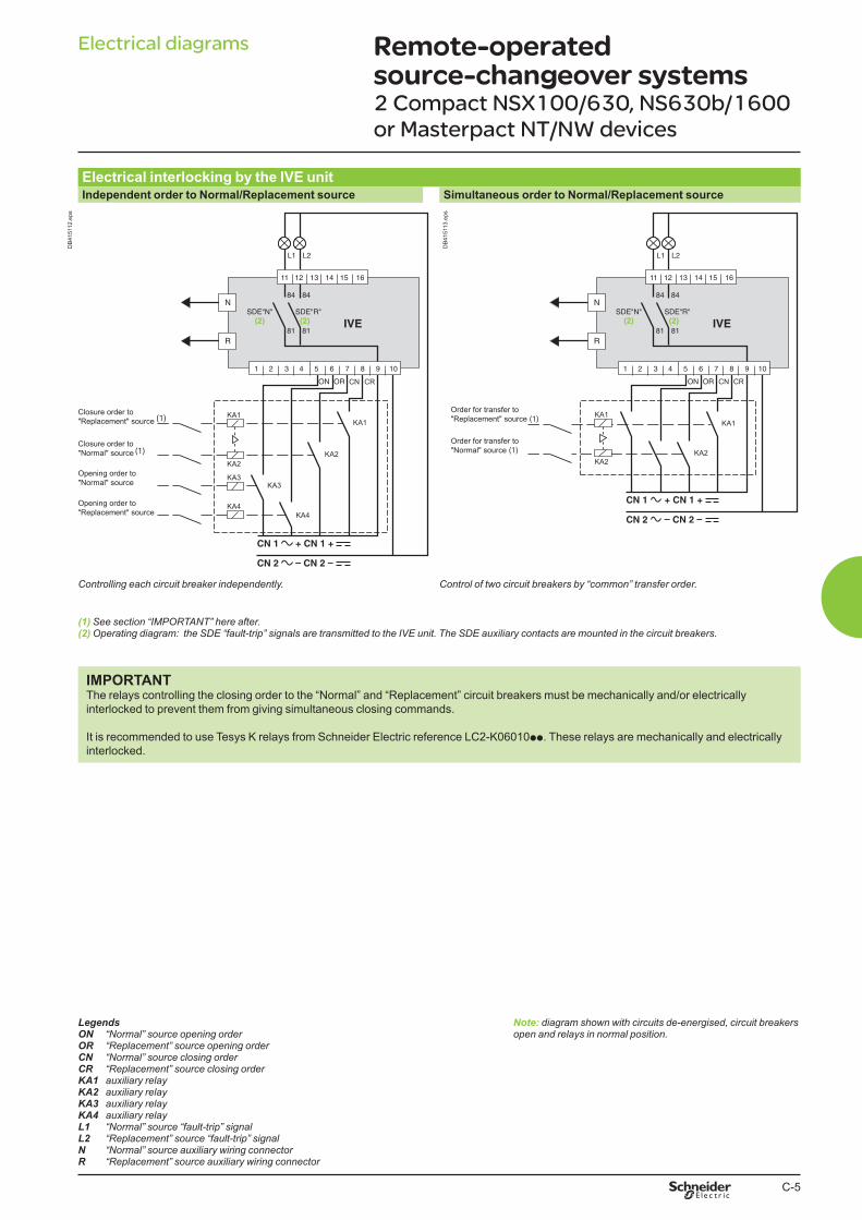
Electrical interlocking by the IVE unitIndependent order to Normal/Replacement source Simultaneous order to Normal/Replacement source
KA1KA1
KA2
KA3
KA4
KA2
KA4
KA3
CN CR
(1)
(1)
Closure order to
"Replacement" source
Closure order to
"Normal" source
Opening order to
"Replacement" source
Opening order to
"Normal" source
DB
415112.e
ps
KA1
KA1
KA2
KA2
CN CR
Order for transfer to
"Normal" source (1)
Order for transfer to
"Replacement" source (1)
DB
415113.e
ps
Controlling each circuit breaker independently. Control of two circuit breakers by “common” transfer order.
(1) See section “IMPORTANT” here after.(2) Operating diagram: the SDE “fault-trip” signals are transmitted to the IVE unit. The SDE auxiliary contacts are mounted in the circuit breakers.
IMPORTANTThe relays controlling the closing order to the “Normal” and “Replacement” circuit breakers must be mechanically and/or electrically
interlocked to prevent them from giving simultaneous closing commands.
It is recommended to use Tesys K relays from Schneider Electric reference LC2-K06010pp. These relays are mechanically and electrically
interlocked.
LegendsON “Normal” source opening orderOR “Replacement” source opening orderCN “Normal” source closing orderCR “Replacement” source closing orderKA1 auxiliary relayKA2 auxiliary relayKA3 auxiliary relayKA4 auxiliary relayL1 “Normal” source “fault-trip” signalL2 “Replacement” source “fault-trip” signalN “Normal” source auxiliary wiring connectorR “Replacement” source auxiliary wiring connector
Note: diagram shown with circuits de-energised, circuit breakers open and relays in normal position.
Remote-operated source-changeover systems 2 Compact NSX100/630, NS630b/1600
or Masterpact NT/NW devices
313E.indb 5 09/04/2013 13:04:54

C-6
Electrical diagrams
Source-changeover system with UA controllerLoad shedding and genset management
Transfer conditions
Terminals 20 and 21:
additional control contact (not part of
controller).
Tests on “Normal” and “Replacement”
source voltages
“Normal” source voltage UN test
“Replacement” source voltage UR test
The single-phase check for UR is
implemented across terminals 1 and 5
of circuit breaker Q2.
LegendsQ1 circuit breaker supplying and protecting the automatic-
control circuits for the “Normal” sourceQ2 circuit breaker supplying and protecting the automatic-
control circuits for the “Replacement” sourceACP control plateUA automatic controllerIVE electrical interlocking and terminal block unit
Note: diagram shown with circuits de-energised, circuit breakers open and relays in normal position.
Source-changeover systems with automatic controllers2 Compact NSX100/630, NS630b/1600
or Masterpact NT/NW devices
313E.indb 6 09/04/2013 13:04:55

Electrical diagrams
Source changeover system with UA controllerController settings Using communication functions
Tests on “Normal” source voltage
A = 0 single-phase test,
A = 1 three-phase test.
Voluntary transfert (e.g. for energy management)
b action in the event of genset failure
B = 0 circuit breaker N opens,
B = 1 circuit breaker N remains closed.
b maximum permissible genset startup time (T6)
C = 0 T = 120 s,
C = 1 T = 180 s.
After this time has elapsed, the genset is considered to
have failed.
The address of the UA 150 controller is set using
the two BBus dials.
Source-changeover systems with automatic controllersController settings
313E.indb 7 09/04/2013 13:04:55

C-8
Electrical diagrams
Source-changeover system with BA controllerCoupling
Transfer conditions
Terminals 20 and 21:
additional control contact (not part of
controller).
Tests on “Normal” and “Replacement”
source voltages
The single-phase check for UN and UR
is implemented across terminals 1 and 5
of circuit breakers Q1 and Q2.
LegendsQ1 circuit breaker supplying and protecting the automatic-
control circuits for the “Normal” sourceQ2 circuit breaker supplying and protecting the automatic-
control circuits for the “Replacement” sourceACP control plateBA automatic controllerIVE electrical interlocking and terminal block unit
Note: diagram shown with circuits de-energised, circuit breakers open and relays in normal position.
Source-changeover systems with automatic controllers2 Compact NSX100/630, NS630b/1600
or Masterpact NT/NW devices
313E.indb 8 09/04/2013 13:04:56

C-9
Electrical diagrams
Electrical interlocking by IVE unit
IVE *
* IVE connection see pages C5, C6 or C8
DB
415209.e
ps
ATTENTION (1)(2) Prefabricated wiring supplied.
The diagram shows the electrical wiring for circuit breakers. When wiring the SDE with switch-disconnectors, connect wire BK to terminal 82.
LegendsQN “Normal” source Compact NS630b to 1600QR “Replacement” source Compact NS630b to 1600OF... breaker ON/OFF indication contactSDE “fault-trip” indication contactCE1 “connected-position” indication contact (carriage switch)F1 auxiliary power supply circuit breakerIVE electrical interlocking and terminal block unitON “Normal” source opening orderOR “Replacement” source opening orderCN “Normal” source closing order (0.25 second delay)CR “Replacement” source closing order (0.25 second delay)MT Motor Mechanism
States permitted by mechanical interlocking system
Normal Replacement
0 0
1 0
0 1
Note: after a fault trip, the breaker must be reset manually by pressing its reset button.Diagram shown with circuit breakers in connected position, open, charged, and ready to close.Auxiliary power supply = supply voltage of auxiliary relays (KA...) = supply voltage of electrical auxiliaries (electrical operation, MT...).
Wiring colour codes
RD GN BK VT YE GY WH BN
red green black violet yellow grey white brown
Remote-operated source-changeover systems2 Compact NS630b/1600 devicesDiagram no. 51201183
313E.indb 9 09/04/2013 13:04:56

C-10
Electrical diagrams
Electrical interlocking by IVE unit with emergency off by shunt release
KA5
KA5
Interlocking by IVE see page C5:
- Independent Order to
Normal/Replacement source
- Simultaneous Order to
Normal/Replacement source
KA5
CN CR
DB
415210.e
ps
ATTENTION (1)(2) Prefabricated wiring supplied.
The diagram shows the electrical wiring for circuit breakers. When wiring the SDE with switch-disconnectors, connect wire BK to terminal 82.
LegendsQN “Normal” source Compact NS630b to 1600QR “Replacement” source Compact NS630b to 1600OF... breaker ON/OFF indication contactSDE “fault-trip” indication contactCE1 “connected-position” indication contact (carriage switch)F1 auxiliary power supply circuit breakerIVE electrical interlocking and terminal block unitMX shunt releaseBP emergency off button with latchingKA5 auxiliary relayON “Normal” source opening orderOR “Replacement” source opening orderCN “Normal” source closing order (0.25 second delay)CR “Replacement” source closing order (0.25 second delay)MT Motor Mechanism
States permitted by mechanical interlocking system
Normal Replacement
0 0
1 0
0 1
Note: after a fault trip, the breaker must be reset manually by pressing its reset button.Diagram shown with circuit breakers in connected position, open, charged, and ready to close.Auxiliary power supply = supply voltage of auxiliary relays (KA...) = supply voltage of electrical auxiliaries (electrical operation, MX, MT...).
Wiring colour codes
RD GN BK VT YE GY WH BN
red green black violet yellow grey white brown
Remote-operated source-changeover systems 2 Compact NS630b/1600 devicesDiagram no. 51201184
313E.indb 10 09/04/2013 13:04:57

C-11
Electrical diagrams
Electrical interlocking by IVE unit with emergency off by undervoltage release
CN CR
KA5
KA5
Interlocking by IVE see page C5:
- Independent Order to
Normal/Replacement source
- Simultaneous Order to
Normal/Replacement source
KA5
DB
415211.e
ps
ATTENTION (1)(2) Prefabricated wiring supplied.
The diagram shows the electrical wiring for circuit breakers. When wiring the SDE with switch-disconnectors, connect wire BK to terminal 82.
LegendsQN “Normal” source Compact NS630b to 1600QR “Replacement” source Compact NS630b to 1600OF... breaker ON/OFF indication contactSDE “fault-trip” indication contactCE1 “connected-position” indication contact (carriage switch)F1 auxiliary power supply circuit breakerIVE electrical interlocking and terminal block unitMN undervoltage releaseBP emergency off button with latchingKA5 auxiliary relayON “Normal” source opening orderOR “Replacement” source opening orderCN “Normal” source closing order (0.25 second delay)CR “Replacement” source closing order (0.25 second delay)MT Motor Mechanism
States permitted by mechanical interlocking system
Normal Replacement
0 0
1 0
0 1
Note: after a fault trip, the breaker must be reset manually by pressing its reset button.Diagram shown with circuit breakers in connected position, open, charged, and ready to close.Auxiliary power supply = supply voltage of auxiliary relays (KA...) = supply voltage of electrical auxiliaries (electrical operation, MN, MT...).
Wiring colour codes
RD GN BK VT YE GY WH BN
red green black violet yellow grey white brown
Remote-operated source-changeover systems2 Compact NS630b/1600 devicesDiagram no. 51201185
313E.indb 11 09/04/2013 13:04:57
C-12
Electrical diagrams
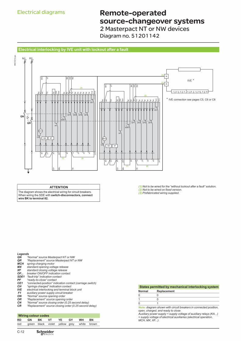
Electrical interlocking by IVE unit with lockout after a fault
IVE *
* IVE connection see pages C5, C6 or C8
DB
415212.e
ps
ATTENTION (1) Not to be wired for the “without lockout after a fault” solution.(2)(3) Prefabricated wiring supplied.The diagram shows the electrical wiring for circuit breakers.
When wiring the SDE with switch-disconnectors, connect wire BK to terminal 82.
LegendsQN “Normal” source Masterpact NT or NWQR “Replacement” source Masterpact NT or NWMCH spring-charging motorMX standard opening voltage releaseXF standard closing voltage releaseOF... breaker ON/OFF indication contactSDE1 “fault-trip” indication contactPF “ready-to-close” contactCE1 “connected-position” indication contact (carriage switch)CH “springs charged” indication contactIVE electrical interlocking and terminal block unit F1 auxiliary power supply circuit breakerON “Normal” source opening orderOR “Replacement” source opening orderCN “Normal” source closing order (0.25 second delay)CR “Replacement” source closing order (0.25 second delay)
States permitted by mechanical interlocking system
Normal Replacement
0 0
1 0
0 1
Note: diagram shown with circuit breakers in connected position, open, charged, and ready to close.Auxiliary power supply = supply voltage of auxiliary relays (KA...) = supply voltage of electrical auxiliaries (electrical operation, MCH, MX, XF...).
Wiring colour codes
RD GN BK VT YE GY WH BN
red green black violet yellow grey white brown
Remote-operated source-changeover systems0
2 Masterpact NT or NW devicesDiagram no. 51201142
313E.indb 12 09/04/2013 13:04:58

C-13
Electrical diagrams
Electrical interlocking by IVE unit with lockout after a fault and emergency off by shunt release
KA5
KA5
Interlocking by IVE see page C5:
- Independent Order to
Normal/Replacement source
- Simultaneous Order to
Normal/Replacement source
KA5
CN CR
DB
415213.e
ps
ATTENTION (1) Not to be wired for the “without lockout after a fault” solution.(2)(3) Prefabricated wiring supplied.The diagram shows the electrical wiring for circuit breakers.
When wiring the SDE with switch-disconnectors, connect wire BK to terminal 82.
LegendsQN “Normal” source Masterpact NT or NWQR “Replacement” source Masterpact NT or NWMCH spring-charging motorMX standard opening voltage releaseXF standard closing voltage releaseOF... breaker ON/OFF indication contactSDE1 “fault-trip” indication contactPF “ready-to-close” contactCE1 “connected-position” indication contact (carriage switch)CH “springs charged” indication contactIVE electrical interlocking and terminal block unitKA5 auxiliary relayF1 auxiliary power supply circuit breakerBP emergency off button with latchingON “Normal” source opening orderOR “Replacement” source opening orderCN “Normal” source closing order (0.25 second delay)CR “Replacement” source closing order (0.25 second delay)
States permitted by mechanical interlocking system
Normal Replacement
0 0
1 0
0 1
Note: diagram shown with circuit breakers in connected position, open, charged, and ready to close.Auxiliary power supply = supply voltage of auxiliary relays (KA...) = supply voltage of electrical auxiliaries (electrical operation, MCH, MX, XF...).
Wiring colour codes
RD GN BK VT YE GY WH BN
red green black violet yellow grey white brown
Remote-operated source-changeover systems2 Masterpact NT or NW devicesDiagram no. 51201143
313E.indb 13 09/04/2013 13:04:59

C-14
Electrical diagrams
Electrical interlocking by IVE unit with lockout after a fault and emergency off by undervoltage release
Interlocking by IVE see page C5:
- Independent Order to
Normal/Replacement source
- Simultaneous Order to
Normal/Replacement source
KA5
KA5
KA5
CN CR
DB
415214.e
ps
ATTENTION (1) Not to be wired for the “without lockout after a fault” solution.(2)(3) Prefabricated wiring supplied.The diagram shows the electrical wiring for circuit breakers.
When wiring the SDE with switch-disconnectors, connect wire BK to terminal 82.
LegendsQN “Normal” source Masterpact NT or NWQR “Replacement” source Masterpact NT or NWMCH spring-charging motorMX standard opening voltage releaseXF standard closing voltage releaseMN undervoltage releaseOF... breaker ON/OFF indication contactSDE1 “fault-trip” indication contactPF “ready-to-close” contactCE1 “connected-position” indication contact (carriage switch)CH “springs charged” indication contactIVE electrical interlocking and terminal block unitKA5 auxiliary relayF1 auxiliary power supply circuit breakerBP emergency off button with latchingON “Normal” source opening orderOR “Replacement” source opening orderCN “Normal” source closing order (0.25 second delay)CR “Replacement” source closing order (0.25 second delay)
States permitted by mechanical interlocking system
Normal Replacement
0 0
1 0
0 1
Note: diagram shown with circuit breakers in connected position, open, charged, and ready to close.Auxiliary power supply = supply voltage of auxiliary relays (KA...) = supply voltage of electrical auxiliaries (electrical operation, MCH, MX, MN, XF...).
Wiring colour codes
RD GN BK VT YE GY WH BN
red green black violet yellow grey white brown
Remote-operated source-changeover systems2 Masterpact NT or NW devicesDiagram no. 51201144
313E.indb 14 09/04/2013 13:04:59

C-15
Electrical diagrams
Automatic-control system for permanent replacement source with lockout after a fault (with MN)
DB
414899.e
ps
ATTENTION (1) Not to be wired for the “without lockout after a fault” solution.(2)(3) Prefabricated wiring supplied.The diagram shows the electrical wiring for circuit breakers.
When wiring the SDE with switch-disconnectors, connect wire BK to terminal 82.
IMPORTANTThe relays controlling the closing order to the “Normal” and “Replacement” circuit breakers must be mechanically and/or electrically
interlocked to prevent them from giving simultaneous closing commands.
It is recommended to use Tesys K relays from Schneider Electric reference LC2-K06010pp. These relays are mechanically and electrically
interlocked.
LegendsQN “Normal” source Masterpact NT or NWQR “Replacement” source Masterpact NT or NWMCH spring-charging motorXF standard closing voltage releaseMN undervoltage releaseOF... breaker ON/OFF indication contactSDE1 “fault-trip” indication contactPF “ready-to-close” contactCE1 “connected-position” indication contact (carriage switch)CH “springs charged” indication contactIVE electrical interlocking and terminal block unitF1 auxiliary power supply circuit breakerF2 circuit breaker (high breaking capacity)S1 control switchesKA1 auxiliary relaysKA2 auxiliary relaysKA3 auxiliary relays
States permitted by mechanical interlocking system
Normal Replacement
0 0
1 0
0 1
Note: diagram shown with circuit breakers in connected position, open, charged, and ready to close.Auxiliary power supply = supply voltage of auxiliary relays (KA...) = supply voltage of electrical auxiliaries (electrical operation, MCH, MN, XF...).
Wiring colour codes
RD GN BK VT YE GY WH BN
red green black violet yellow grey white brown
Remote-operated source-changeover systems2 Masterpact NT or NW devicesDiagram no. 51156904
313E.indb 15 09/04/2013 13:05:00

C-16
Electrical diagrams
Automatic-control system for replacement source generator set with lockout after a fault (with MN)
DB
414900.e
ps
ATTENTION (1) Not to be wired for the “without lockout after a fault” solution.(2)(3) Prefabricated wiring supplied.
The diagram shows the electrical wiring for circuit breakers. When wiring the SDE with switch-disconnectors, connect wire BK to terminal 82.
IMPORTANTThe relays controlling the closing order to the “Normal” and “Replacement” circuit breakers must be mechanically and/or electrically
interlocked to prevent them from giving simultaneous closing commands.
It is recommended to use Tesys K relays from Schneider Electric reference LC2-K06010pp. These relays are mechanically and electrically
interlocked.
LegendsQN “Normal” source Masterpact NT or NWQR “Replacement” source Masterpact NT or NWMCH spring-charging motorXF standard closing voltage releaseMN undervoltage releaseOF... breaker ON/OFF indication contactSDE1 “fault-trip” indication contactPF “ready-to-close” contactCE1 “connected-position” indication contact (carriage switch)CH “springs charged” indication contactIVE electrical interlocking and terminal block unitF1 auxiliary power supply circuit breakerF2 circuit breaker (high breaking capacity)S1 control switchesKA1 auxiliary relayKA2 time delay for genset startup order to avoid starting
the genset for transient UN disturbancesKA3 auxiliary relay
States permitted by mechanical interlocking systemNormal Replacement
0 0
1 0
0 1
Note: diagram shown with circuit breakers in connected position, open, charged, and ready to close.Auxiliary power supply = supply voltage of auxiliary relays (KA...) = supply voltage of electrical auxiliaries (electrical operation, MCH, MN, XF...).
Wiring colour codes
RD GN BK VT YE GY WH BN
red green black violet yellow grey white brown
Remote-operated source-changeover systems2 Masterpact NT or NW devicesDiagram no. 51156905
313E.indb 16 09/04/2013 13:05:01


