

GAS RETICULATION
SYSTEM
Assoc. Prof. Engr. Dr. Rahmat Bin Mohsin
Mohd. Dinie Muhaimin Samsudin
Storage and Reticulation System SKN 4223 2
TYPE OF GAS PIPELINE SYSTEMS
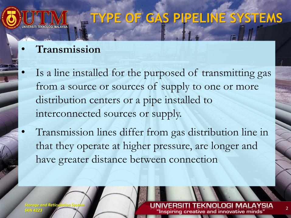
• Transmission
• Is a line installed for the purposed of transmitting gas
from a source or sources of supply to one or more
distribution centers or a pipe installed to
interconnected sources or supply.
• Transmission lines differ from gas distribution line in
that they operate at higher pressure, are longer and
have greater distance between connection
Storage and Reticulation System SKN 4223 3
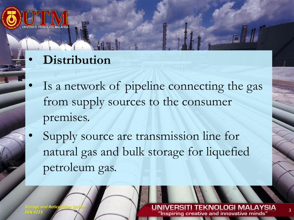
• Distribution
• Is a network of pipeline connecting the gas
from supply sources to the consumer
premises.
• Supply source are transmission line for
natural gas and bulk storage for liquefied
petroleum gas.
Storage and Reticulation System SKN 4223 4
Storage and Reticulation System SKN 4223 5
Storage and Reticulation System SKN 4223 6
GAS PIPE DESIGN COMPONENTS
1. Pipeline optimization
2. Selection and analysis of pipeline route
3. Geotechnical and environmental aspects
4. Engineering survey
5. Route design
6. Buoyancy control
7. Selection of materials
8. Stress analysis
9. Facility design
10. Corrosion control

Storage and Reticulation System SKN 4223 7
Basic Concepts of Gas
Distribution System (Gas Supply)
• Items to ensure stability of supply
High reliability
Low installation cost
Low maintenance
Materials and parts supply facilities
• Supply system is determined based on the serviced
area, volume of gas needed, the capacity of existing
equipment, the possibility of the expansion,
maintenance and control facilities and costs.
Storage and Reticulation System SKN 4223 8
• In making the classification of consumers and
supply system, it is necessary to ensure the system is
safe and secure.
• Supply system is classified to:
1. Large industry -> 1000 cubic meters per hour
2. Medium and small industries
3. Commercial
4. Domestic - <1 cubic meter per hour

Storage and Reticulation System SKN 4223 9
Government Acts
• Systems should be designed to comply with the requirements of the following acts:
• Petroleum Act (Safety Measures) 1984 Cover security measures to be considered in designing and installation of gas and petroleum-related facilities.
• Environmental Quality Act (1974) Act governing the activities that may affect the environment. Identify the mandatory environmental impact study
• Factories and Machinery Act (1967) To enforce the requirements of the tests carried out on a high-pressure gas pipe installation, including welding procedures, welder qualifications and other related.

Storage and Reticulation System SKN 4223 10
Code of Practice and Standards
AGA : American Gas Association
ANSI : American National Standard Institute
ASME : American Society of Mechanical Testing
ASTM : American Society of Testing of Material
API : American Petroleum Institute
BS : British Standard
CSA : Canadian Standard Association
IP : Institute of Petroleum
ISA : Instrumentations Standards Association
MS : Malaysian Standard
MSS : Material Specification Standards
NACE : National Association of Corrosion Engineers
NEMA : National Electrical Manufacturing Association
PTS : Petronas Technical Standard
SIS : Standard Institution of Sweeden
SSPC : Steel Structure Painting Council
Storage and Reticulation System SKN 4223 11
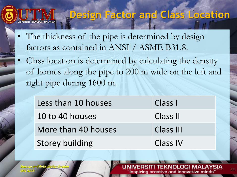
Design Factor and Class Location
• The thickness of the pipe is determined by design
factors as contained in ANSI / ASME B31.8.
• Class location is determined by calculating the density
of homes along the pipe to 200 m wide on the left and
right pipe during 1600 m.
Less than 10 houses Class I
10 to 40 houses Class II
More than 40 houses Class III
Storey building Class IV
Storage and Reticulation System SKN 4223 12
DISTRIBUTION SYSTEM PIPELINE
• Using steel and plastic pipeline with pipe diameter
and pressure lower than the transmission pipeline
system.
• Consists of series of pipes that operate at
different pressures and there is no agreement or a
general statement or terminology on pressure
range for each classification.

Storage and Reticulation System SKN 4223 13
• Before gas distributed to the user, it passes
through a series of gas stations in the system.
1. Local Stations
2. Area Station
3. Service Station
• Installation of the stations subject to the pressure
required by the user.
• Pressure reduced using pressure regulator.
• Odorizer included for security purposes.

Storage and Reticulation System SKN 4223 14
BASIC CONSIDERATION IN SELECTING
THE DISTRIBUTION SYSTEM
• Three main factors should be considered:
1. Estimates the gas consumption rate or gas
demand
2. Selection and assumption of distribution
system (Network analysis)
3. Check the pressure required whether it is
maintained at a specific level

Storage and Reticulation System SKN 4223 15
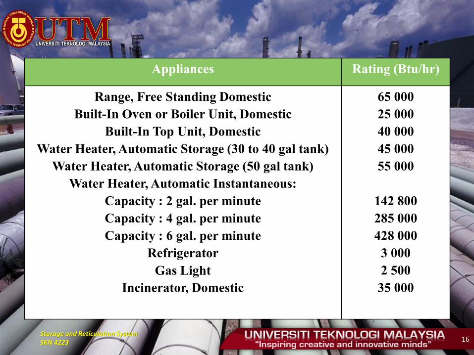
DESIGN DEMAND ESTIMATION
• Determination of the total amount of gas
consumption is among the first requirements for
the determination of the pipe diameter.
• What is required for the determination of the
total amount of gas consumption is the amount
of gas consumption of each combustion
appliances and the number of such appliances to
be installed.
• It can be determined directly from manufacturer.
Storage and Reticulation System SKN 4223 16
Appliances Rating (Btu/hr)
Range, Free Standing Domestic Built-In Oven or Boiler Unit, Domestic
Built-In Top Unit, Domestic Water Heater, Automatic Storage (30 to 40 gal tank)
Water Heater, Automatic Storage (50 gal tank) Water Heater, Automatic Instantaneous:
Capacity : 2 gal. per minute Capacity : 4 gal. per minute Capacity : 6 gal. per minute
Refrigerator Gas Light
Incinerator, Domestic
65 000 25 000 40 000 45 000 55 000
142 800 285 000 428 000 3 000 2 500 35 000

Storage and Reticulation System SKN 4223 17
• However, the amount of gas consumption
can be determine based on various factors
Number of customer
Type of residence
Fuel supply and demand situation
Kind of industries
Future prospect of the subject area
Storage and Reticulation System SKN 4223 18
• In general the total amount of all rating of
appliances does not always amount of the gas that
each consumer uses. This is because, it is rarely the
case that consumers use all their appliances
simultaneously and the appliances are not always to
be used with the fully open.
• Therefore, the amount of gas to be considered as a
design consumption is a total gas consumption
the area multiply with consumption factor which is
called appliance gas coincident factor.
Storage and Reticulation System SKN 4223 19
REQUIRED INFORMATION FOR
SERVICE PIPELINE DESIGN
The following information should be obtained:
• Plant layout
Overall plant layout
Part of plant layout where firing equipment is located
• Location of each burner system
• Required pressure of each equipment
• Future demand
• Location of natural gas service station and for LPG user
Existing LPG piping layout (This drawing must be checked to confirm its actual installation)
LPG supplied pressure
If possible, former LPG piping contractor name
Storage and Reticulation System SKN 4223 20
PIPELINE ROUTE SELECTION
• Avoid side slopes and cross slopes
• Avoid unstable slope
• Avoid any crossing, if possible
river, highway, culvert etc
cross at straight section
• Avoid cemeteries
• Avoid national park or reserve land
• Avoid religious places
• Avoid community places
• Avoid pocket land
Storage and Reticulation System SKN 4223 21
ROUTE OF SERVICES PIPING
SELECTION & CONSIDERATIONS
Following is the criteria to be considered to select services piping route.
• Exposed piping is much better than underground piping for easy maintenance and safety
• Gas piping shall not be installed in/at/through the following places or locations:
a lift shaft
exhaust duct, etc.
electrical facility room, etc.
where it will be subjected to extreme temperature, water or moisture continuously
where it will be subjected to excessive vibration
where it will be subjected to corrosive gas or solution
in concrete slab or cylinder
Storage and Reticulation System SKN 4223 22
• Gas piping shall be securely supported to avoid strain exerting on the pipe. Therefore good pipe support must be considered too.
• The piping and its support must not obstruct the operation of any factory's mobile machine i.e. forklift and crane.
• Planning or possible expansion or modification of factory
where the future demand will be
whether the construction (of the expansion) will cause unsafe condition or modification required to the piping system.
Storage and Reticulation System SKN 4223 23
• The construction or installation work of the
piping shall least affect the production or
operation of the factory.
• PE pipe shall not be installed as exposed pipe.
• The radius of the inner curve of PE pipe
bending (R) shall not less than 25 times of inner
diameter of the pipe.
Storage and Reticulation System SKN 4223 24
• Location of customer's monitoring meter and
line of equipment/regulator shall be located in
ventilated spaces readily accessible for
examination, servicing or replacement.
• Piping system shall be as simple as possible to
avoid confusion, especially in case of existing
LPG piping remained.
• The loop of piping shall not be use for internal
piping

Storage and Reticulation System SKN 4223 25
SIZING OF GAS PIPING FOR
SERVICE LINE
• Is a line connected from the street main to the
customer's meter.
• Gas piping shall be of such size and so installed
as to provide a supply of gas sufficient to meet
demand without undue pressure drop between
service station and gas appliances.
Storage and Reticulation System SKN 4223 26
• Several points need to be considered when sizing the pipe;
2 ½ and 5 inches pipe shall not be used for new piping system except for a special case. These two pipes are not common in the market.
The pipe size of the piping system shall not be changed except for branches and connection for meters, regulators, isolation valves or special case such as tie-in point to existing piping etc.
The pipe size of the downstream pipe shall not be larger than upstream except the connection for meters, regulators, isolation valves etc. And the downstream pipe of meters or regulator must be adequate size for distributing condition.
Storage and Reticulation System SKN 4223 27
• The minimum pipe size for welding is recommended to be 1 inch.
• Factors influence the service line sizing are:
Total connected load
Length of service line
Pressure at the main
• There are four methods widely used to solved the above task as called a quit and simple calculation (not as complex as general gas flow equation).
NFPA No. 54 (National Fire Protection Association) Method
Clifford Method
Cox's Formula
Pauls’s Formula
Storage and Reticulation System SKN 4223 28
Elevation Effect to Low Pressure
System
• Consider gas with specific gravity of S at static
height of 1m:
At datum:
• Atmospheric pressure : Pa mbar
• Gauge Pressure : Pg mbar
• Absolute pressure : Pa + Pg mbar
Storage and Reticulation System SKN 4223 29
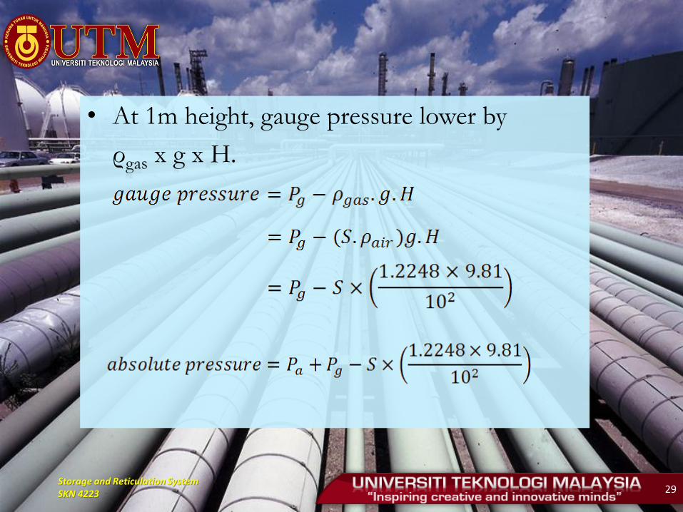
• At 1m height, gauge pressure lower by
ρgas x g x H.
Storage and Reticulation System SKN 4223 30
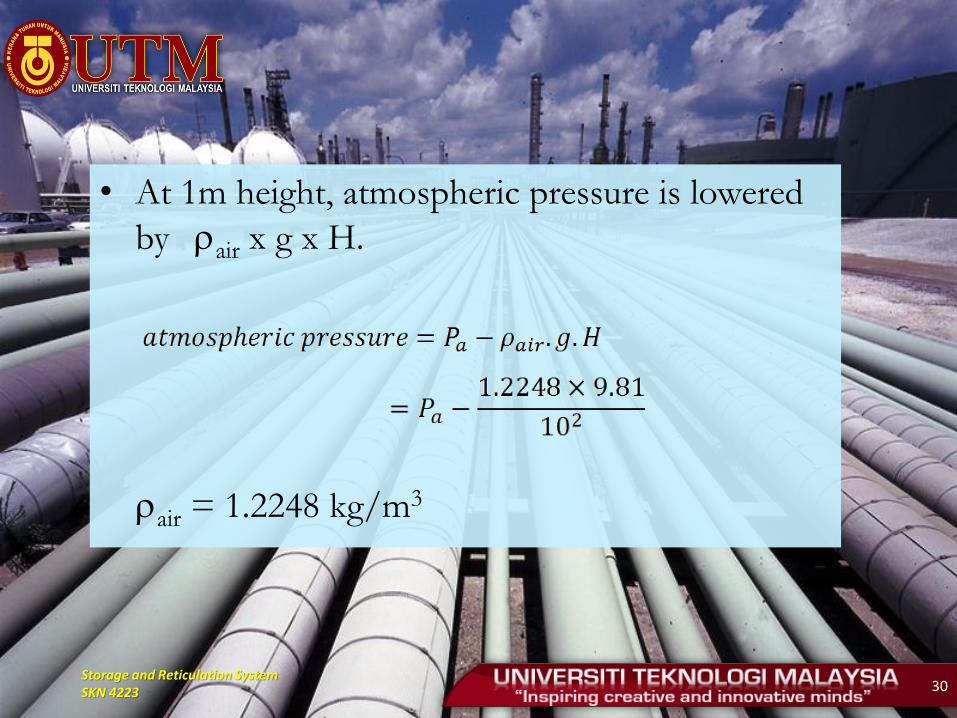
• At 1m height, atmospheric pressure is lowered
by rair x g x H.
rair = 1.2248 kg/m3
Storage and Reticulation System SKN 4223 31
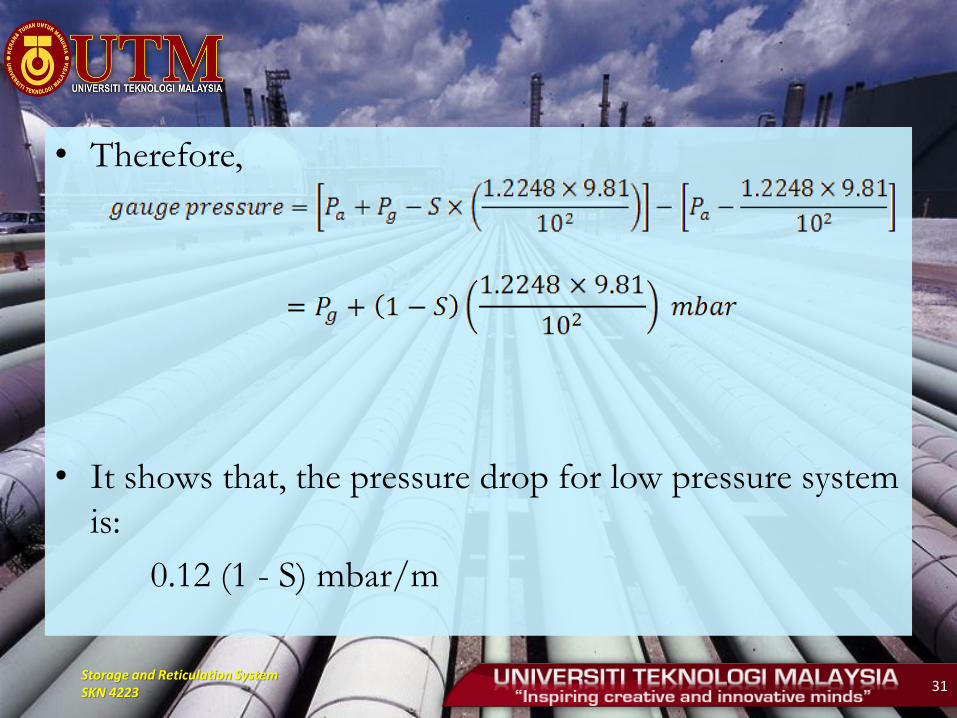
• Therefore,
• It shows that, the pressure drop for low pressure system
is:
0.12 (1 - S) mbar/m
Storage and Reticulation System SKN 4223 32
COX'S FORMULA
• Supply Pressure is/above 29.4 kPa.G (3000
mmH2O).
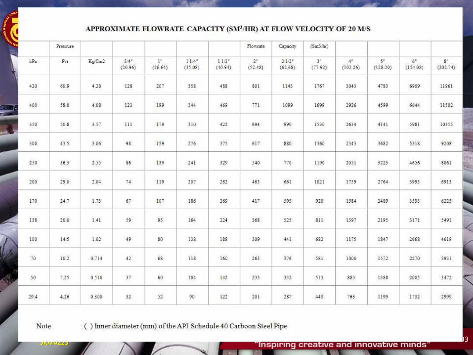
• The pipe size of each section or portion shall be pre-
determined by using Table, which shows the
maximum flow capacity at various pressure to ensure
the flow velocity at various pressure to ensure the
flow velocity does not exceed 20 m/s.
Storage and Reticulation System SKN 4223 33
Storage and Reticulation System SKN 4223 34
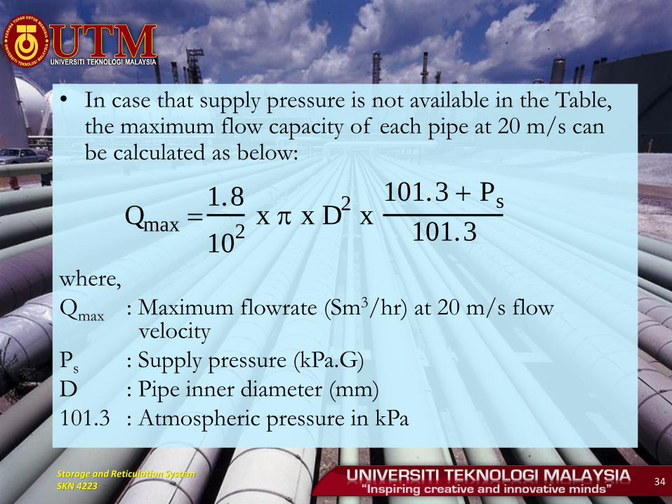
• In case that supply pressure is not available in the Table, the maximum flow capacity of each pipe at 20 m/s can be calculated as below:
where,
Qmax : Maximum flowrate (Sm3/hr) at 20 m/s flow velocity
Ps : Supply pressure (kPa.G)
D : Pipe inner diameter (mm)
101.3 : Atmospheric pressure in kPa
Qmax 1.8
102 x x D
2 x
101.3 Ps
101.3
Storage and Reticulation System SKN 4223 35
• The pressure drop of the size pre-determined above to each appliance system shall be calculated by Cox's Formula as shown below: However, maximum allowable pressure drop is 15% of supply pressure. If not, shall select bigger pipe size for that sections to provide the sufficient pressure or pressure drop within 15% of supply pressure.
• In that case, piping cost effect should be also taken into consideration, so that 2 or more piping sections or portions might be selected to bigger pipe size. This mean that, the down stream pipe size must be bigger size than upstream pipe.
Storage and Reticulation System SKN 4223 36
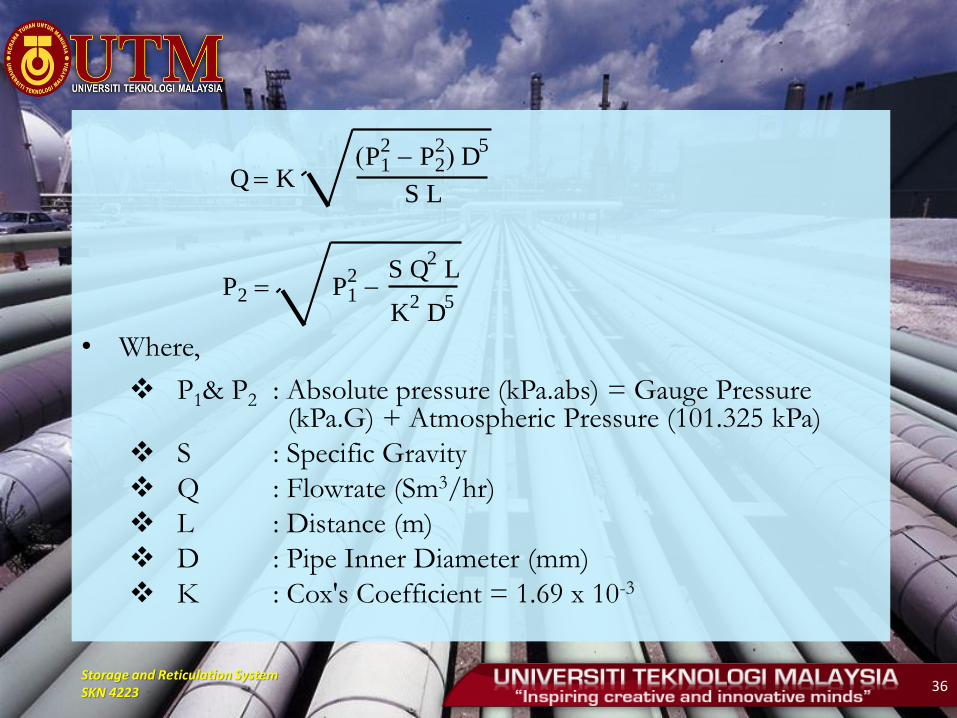
• Where,
P1& P2 : Absolute pressure (kPa.abs) = Gauge Pressure (kPa.G) + Atmospheric Pressure (101.325 kPa)
S : Specific Gravity
Q : Flowrate (Sm3/hr)
L : Distance (m)
D : Pipe Inner Diameter (mm)
K : Cox's Coefficient = 1.69 x 10⁻³
Q K P
21 P
22 D
5
S L
P2 P21
S Q2 L
K2 D
5
Storage and Reticulation System SKN 4223 37
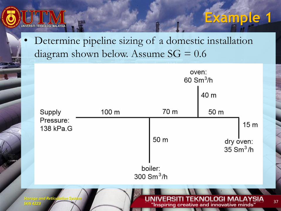
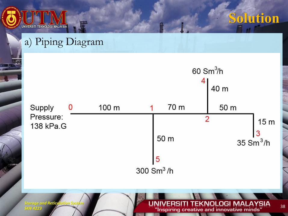
Example 1
• Determine pipeline sizing of a domestic installation
diagram shown below. Assume SG = 0.6
Storage and Reticulation System SKN 4223 38
Solution
a) Piping Diagram
Storage and Reticulation System SKN 4223 39
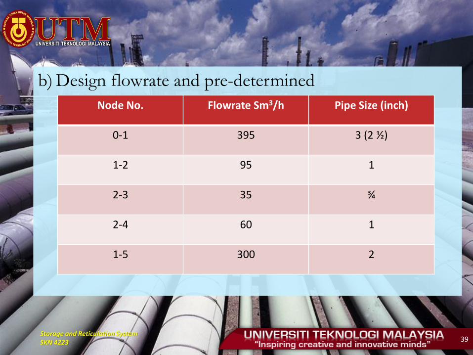
b) Design flowrate and pre-determined
Node No. Flowrate Sm3/h Pipe Size (inch)
0-1 395 3 (2 ½)
1-2 95 1
2-3 35 ¾
2-4 60 1
1-5 300 2
Storage and Reticulation System SKN 4223 40
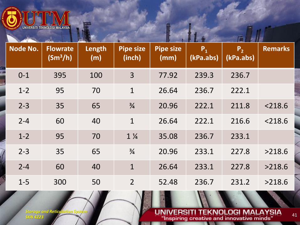
c) Pressure Drop Calculation
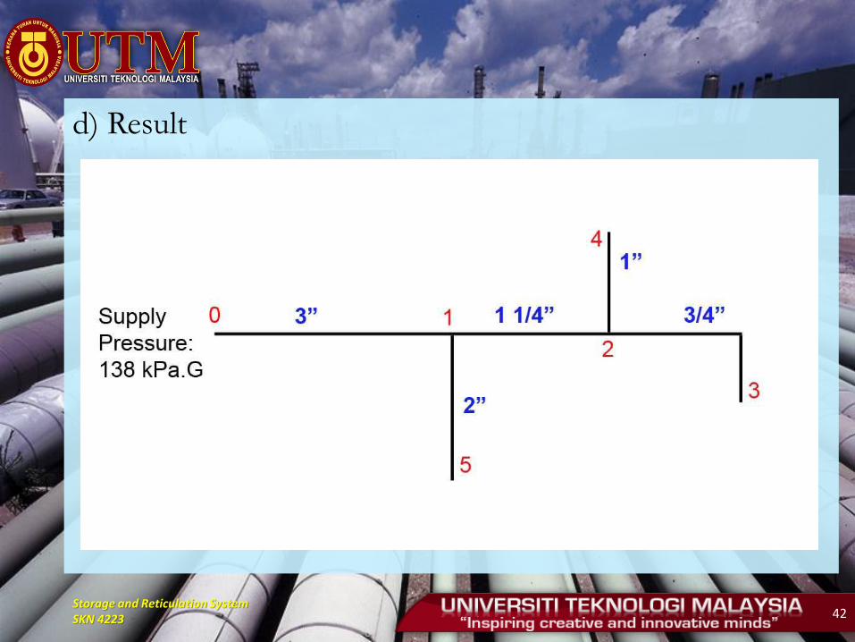
As supply pressure is 138 kPa.G, the minimum pressure to the equipment is 117.3 kPa.G (218.6 kPa.abs). Therefore, pressure drop of each pipe as shown in the following table.
Storage and Reticulation System SKN 4223 41
Node No. Flowrate (Sm3/h)
Length (m)
Pipe size (inch)
Pipe size (mm)
P1 (kPa.abs)
P2 (kPa.abs)
Remarks
0-1 395 100 3 77.92 239.3 236.7
1-2 95 70 1 26.64 236.7 222.1
2-3 35 65 ¾ 20.96 222.1 211.8 <218.6
2-4 60 40 1 26.64 222.1 216.6 <218.6
1-2 95 70 1 ¼ 35.08 236.7 233.1
2-3 35 65 ¾ 20.96 233.1 227.8 >218.6
2-4 60 40 1 26.64 233.1 227.8 >218.6
1-5 300 50 2 52.48 236.7 231.2 >218.6
Storage and Reticulation System SKN 4223 42
d) Result
Storage and Reticulation System SKN 4223 43
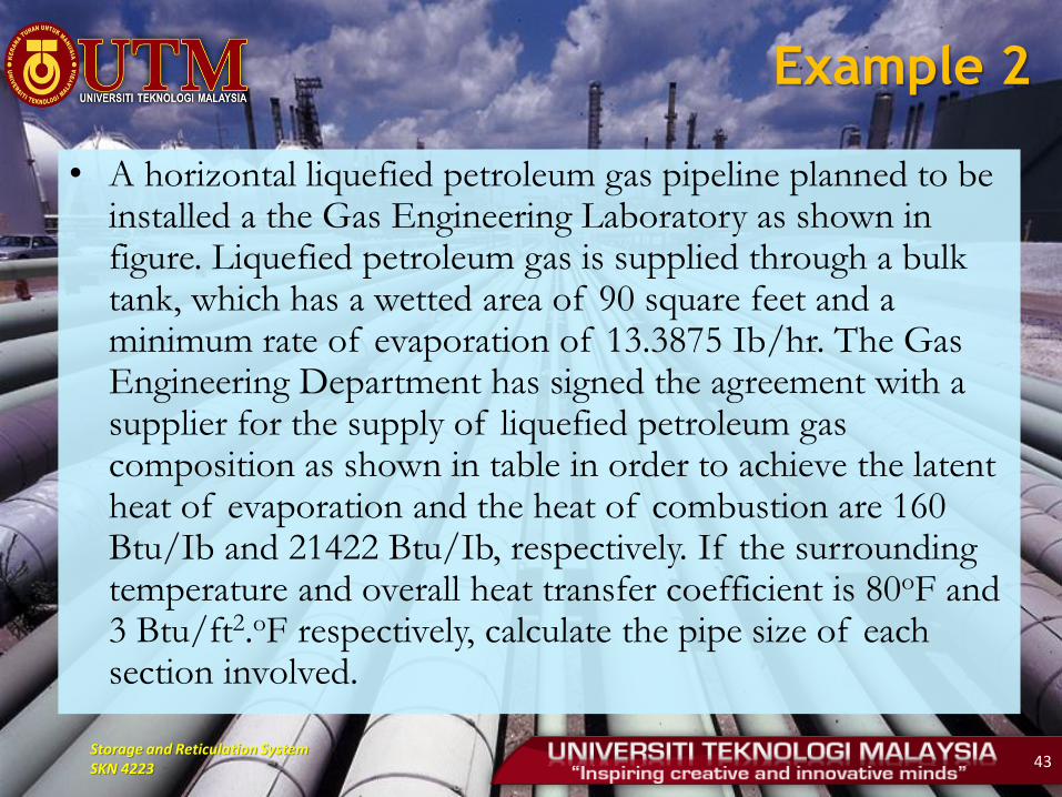
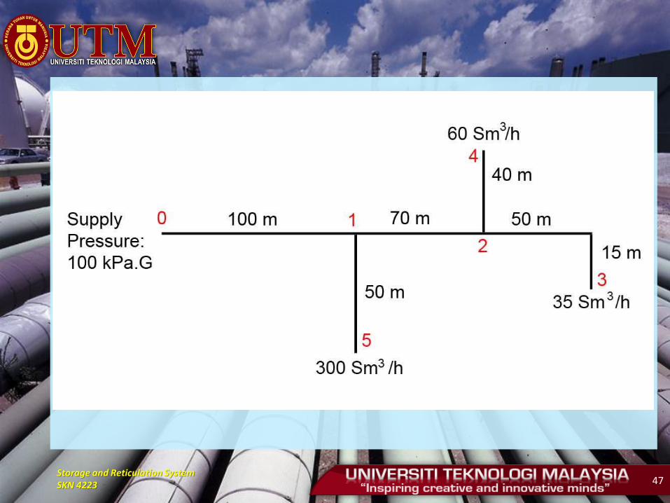
Example 2
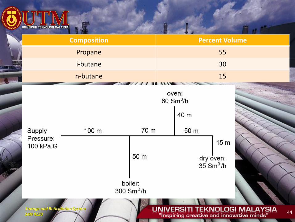
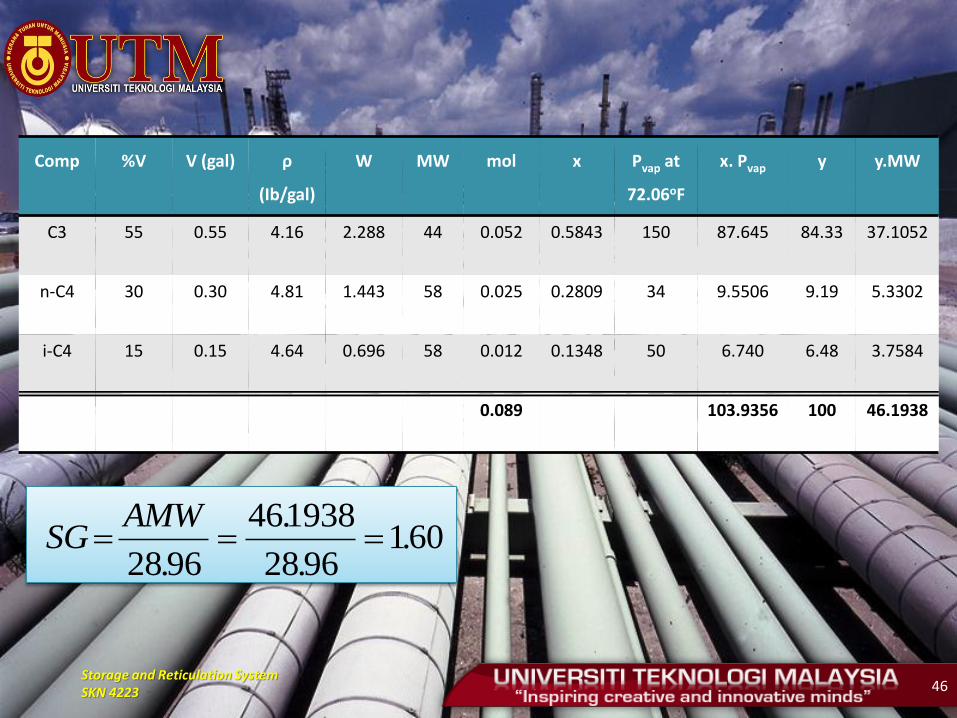
• A horizontal liquefied petroleum gas pipeline planned to be installed a the Gas Engineering Laboratory as shown in figure. Liquefied petroleum gas is supplied through a bulk tank, which has a wetted area of 90 square feet and a minimum rate of evaporation of 13.3875 Ib/hr. The Gas Engineering Department has signed the agreement with a supplier for the supply of liquefied petroleum gas composition as shown in table in order to achieve the latent heat of evaporation and the heat of combustion are 160 Btu/Ib and 21422 Btu/Ib, respectively. If the surrounding temperature and overall heat transfer coefficient is 80oF and 3 Btu/ft2.oF respectively, calculate the pipe size of each section involved.
Storage and Reticulation System SKN 4223 44
Composition Percent Volume
Propane 55
i-butane 30
n-butane 15
Storage and Reticulation System SKN 4223 45
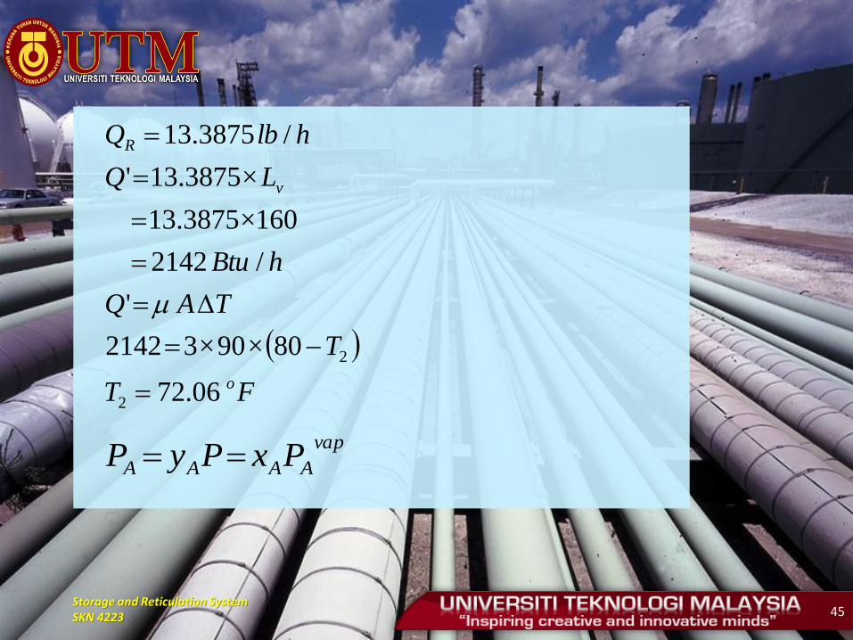
FT
T
TAQ
hBtu
LQ
hlbQ
o
v
R
06.72
80×90×32142
'
/2142
160×3875.13
×3875.13'
/3875.13
2
2
vap
AAAA PxPyP
Storage and Reticulation System SKN 4223 46
Comp %V V (gal) ρ
(Ib/gal)
W MW mol x Pvap at
72.06oF
x. Pvap y y.MW
C3 55 0.55 4.16 2.288 44 0.052 0.5843 150 87.645 84.33 37.1052
n-C4 30 0.30 4.81 1.443 58 0.025 0.2809 34 9.5506 9.19 5.3302
i-C4 15 0.15 4.64 0.696 58 0.012 0.1348 50 6.740 6.48 3.7584
0.089 103.9356 100 46.1938
6019628
193846
9628.
.
.
.
AMWSG
Storage and Reticulation System SKN 4223 47
Storage and Reticulation System SKN 4223 48
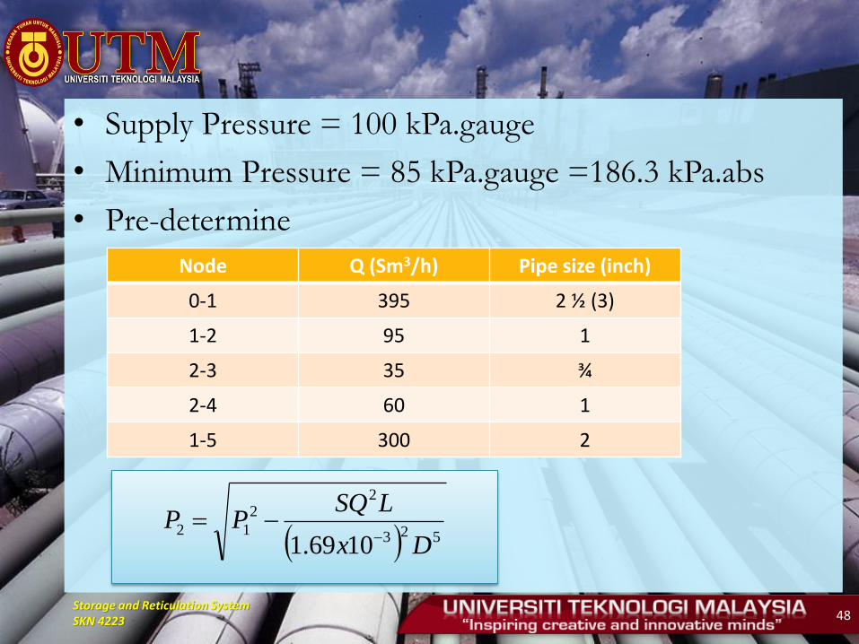
• Supply Pressure = 100 kPa.gauge
• Minimum Pressure = 85 kPa.gauge =186.3 kPa.abs
• Pre-determine
Node Q (Sm3/h) Pipe size (inch)
0-1 395 2 ½ (3)
1-2 95 1
2-3 35 ¾
2-4 60 1
1-5 300 2
523
22
12
1069.1 Dx
LSQPP
Storage and Reticulation System SKN 4223 49
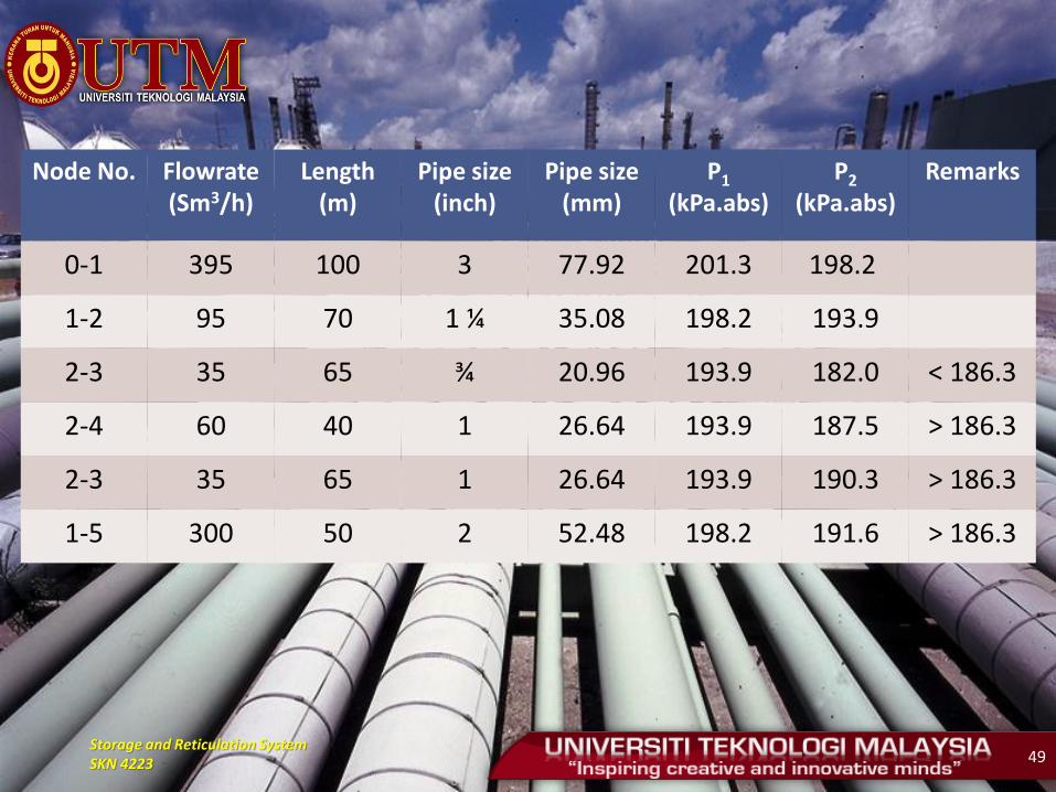
Node No. Flowrate (Sm3/h)
Length (m)
Pipe size (inch)
Pipe size (mm)
P1 (kPa.abs)
P2 (kPa.abs)
Remarks
0-1 395 100 3 77.92 201.3 198.2
1-2 95 70 1 ¼ 35.08 198.2 193.9
2-3 35 65 ¾ 20.96 193.9 182.0 < 186.3
2-4 60 40 1 26.64 193.9 187.5 > 186.3
2-3 35 65 1 26.64 193.9 190.3 > 186.3
1-5 300 50 2 52.48 198.2 191.6 > 186.3
Storage and Reticulation System SKN 4223 50

Storage and Reticulation System SKN 4223 51
PAUL'S FORMULA
• Supply Pressure is less than 29.4 kPa.G (3000 mmH2O)
• Pressure drop of each section can be calculated by Paul's Formula as shown below:
ΔP : Pressure drop (Pa)
K2 : Paul's coefficient
= 7.09 x 10⁻⁴
D : Pipe inner diameter (mm)
S : Specific gravity of gas
L : Pipe length (m)
Q : Flowrate (Sm3/hr)
Q K2 P D
5
S. L
or
P S
K2 D5 x Q
2 L
Storage and Reticulation System SKN 4223 52
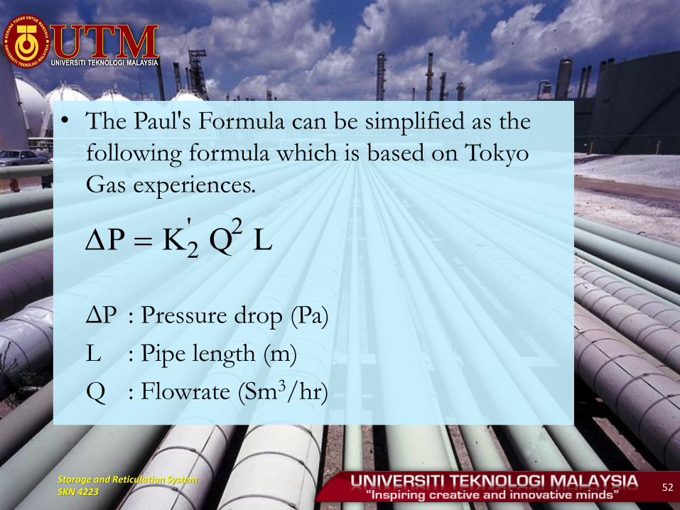
• The Paul's Formula can be simplified as the
following formula which is based on Tokyo
Gas experiences.
ΔP : Pressure drop (Pa)
L : Pipe length (m)
Q : Flowrate (Sm3/hr)
P K'2 Q
2 L
Storage and Reticulation System SKN 4223 53
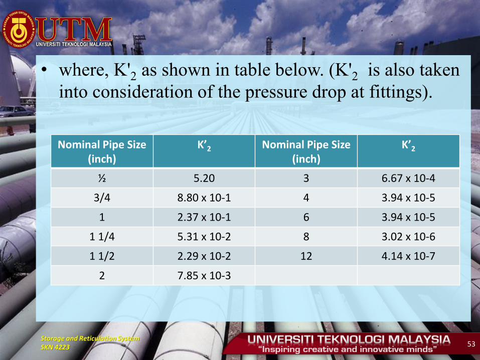
• where, K'2 as shown in table below. (K'2 is also taken
into consideration of the pressure drop at fittings).
Nominal Pipe Size (inch)
K’2 Nominal Pipe Size (inch)
K’2
½ 5.20 3 6.67 x 10⁻⁴
3/4 8.80 x 10⁻¹ 4 3.94 x 10⁻⁵
1 2.37 x 10⁻¹ 6 3.94 x 10⁻⁵
1 1/4 5.31 x 10⁻² 8 3.02 x 10⁻⁶
1 1/2 2.29 x 10⁻² 12 4.14 x 10⁻⁷
2 7.85 x 10⁻³
Storage and Reticulation System SKN 4223 54
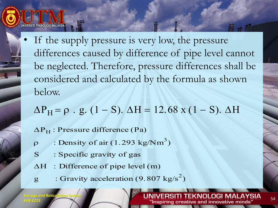
• If the supply pressure is very low, the pressure
differences caused by difference of pipe level cannot
be neglected. Therefore, pressure differences shall be
considered and calculated by the formula as shown
below.
PH r . g. 1 S. H 12.68 x 1 S. H
PH : Pressure difference Pa
r : Density of air 1.293 kg/Nm3
S : Specific gravity of gas
Difference of pipe level m
g : Gravity acceleration 9.807 kg/s2
Storage and Reticulation System SKN 4223 55
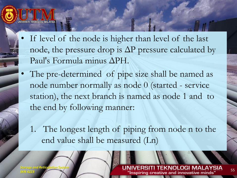
• If level of the node is higher than level of the last
node, the pressure drop is ΔP pressure calculated by
Paul's Formula minus ΔPH.
• The pre-determined of pipe size shall be named as
node number normally as node 0 (started - service
station), the next branch is named as node 1 and to
the end by following manner:
1. The longest length of piping from node n to the
end value shall be measured (Ln)
Storage and Reticulation System SKN 4223 56
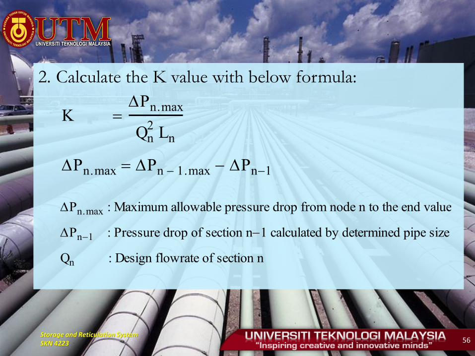
2. Calculate the K value with below formula:
K
Pn.max
Q2n Ln
Pn.max Pn 1.max Pn1
Pn.max : Maximum allowable pressure drop from node n to the end value
Pn1 : Pressure drop of section n1 calculated by determined pipe size
Qn : Design flowrate of section n

Storage and Reticulation System SKN 4223 57
3. Compare K value to K'2 value shown in the
table. Then find out the appropriate pipe size of
corresponding K'2 (the value selected for K'2
should be less than K value). The selected pipe
size is known as pre-determined pipe size for
section n.
4. Pn shall be calculated by Paul's Formula
5. Repeat (1) – (4) to determine the pipe size of
section n + 1 until the end section.
Storage and Reticulation System SKN 4223 58
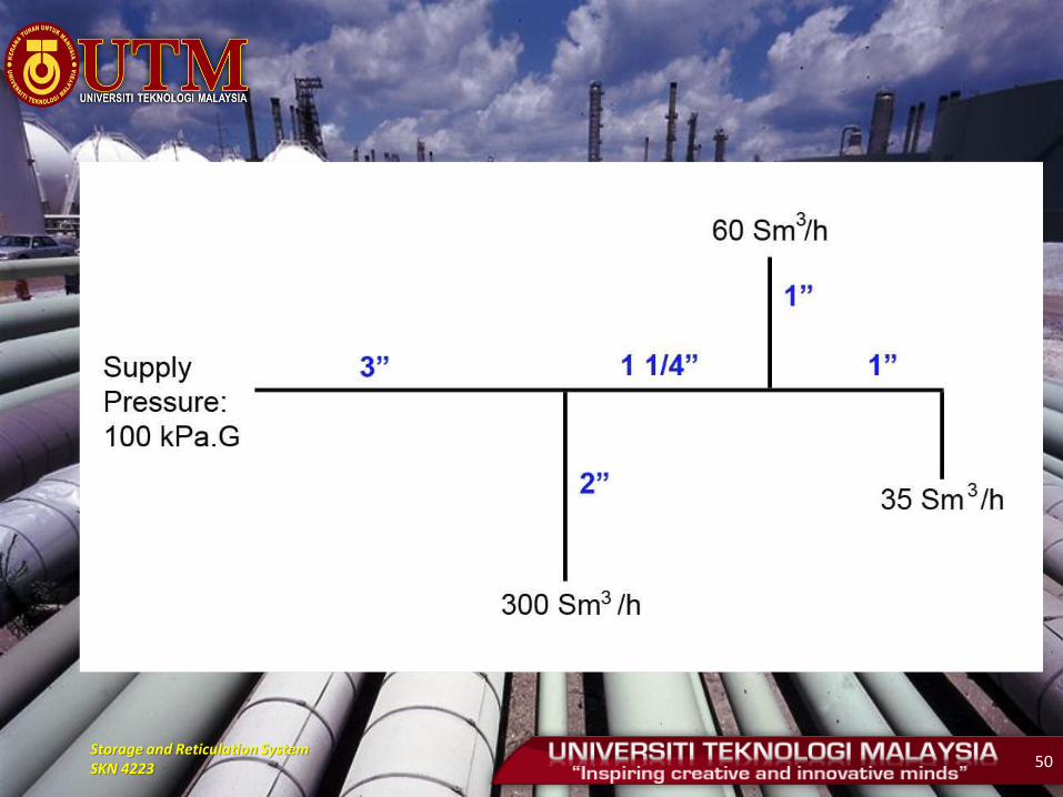
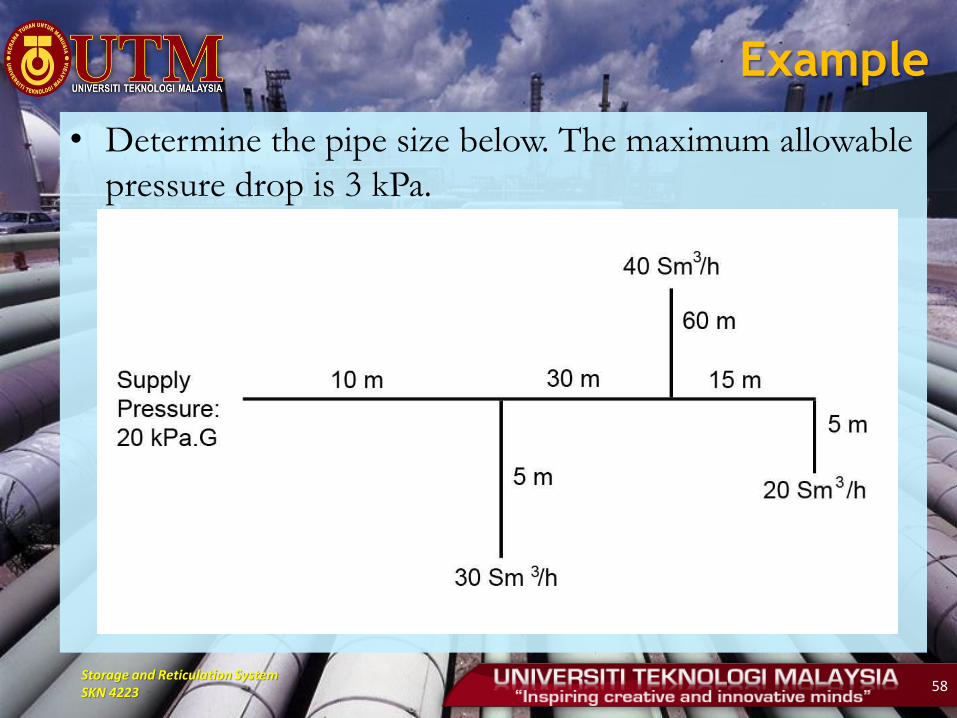
Example
• Determine the pipe size below. The maximum allowable
pressure drop is 3 kPa.

Storage and Reticulation System SKN 4223 59
Solution

Storage and Reticulation System SKN 4223 60
• Pre-determine pipe size
• The most long pipe length from service station to
equipment is 0 - 4. Then,
• Node 0 to Node 1
K Pn.max
Q2n. Ln
3000
902 x 100
3.7 x 10³
Therefore : Pipe Size 3"
Pressure drop K'2 Q
2 L
6.67 x 104
x 902 x 10 54.0 Pa
Storage and Reticulation System SKN 4223 61
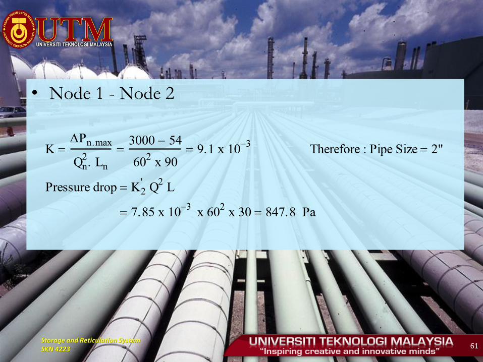
• Node 1 - Node 2
K Pn.max
Q2n. Ln
3000 54
602 x 90
9.1 x 10³
Therefore : Pipe Size 2"
Pressure drop K'2 Q
2 L
7.85 x 103
x 602 x 30 847.8 Pa
Storage and Reticulation System SKN 4223 62
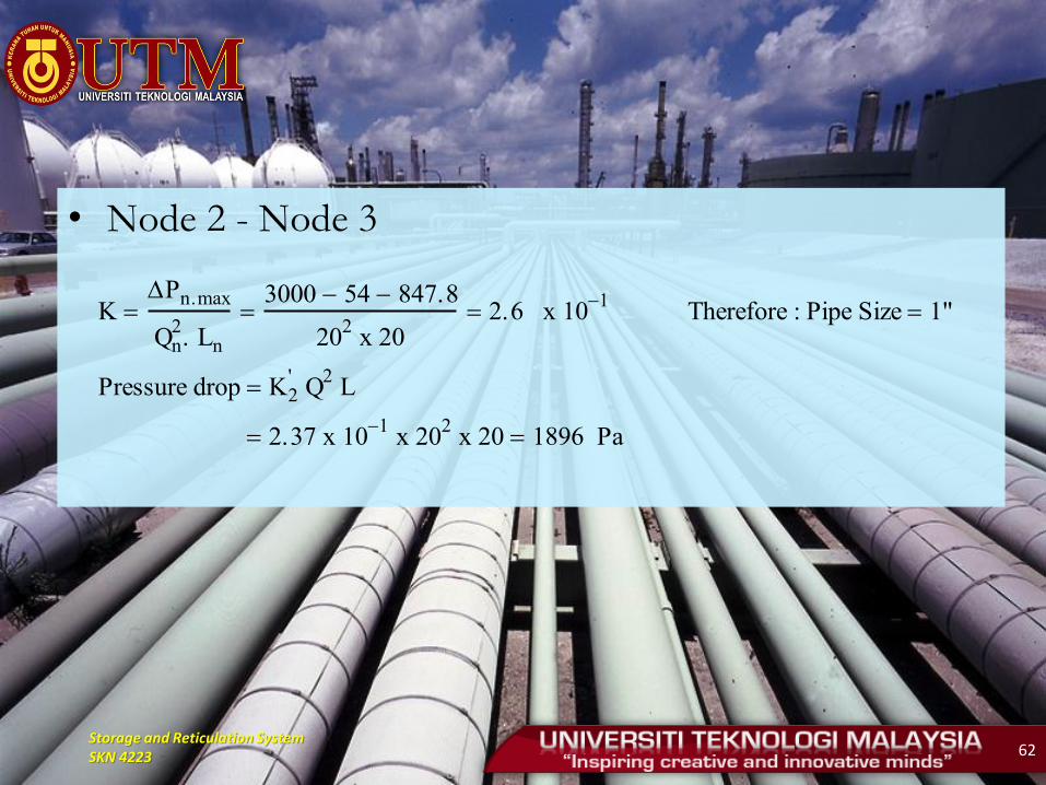
• Node 2 - Node 3
K Pn.max
Q2n. Ln
3000 54 847.8
202 x 20
2.6 x 101
Therefore : Pipe Size 1"
Pressure drop K'2 Q
2 L
2.37 x 101
x 202 x 20 1896 Pa
Storage and Reticulation System SKN 4223 63
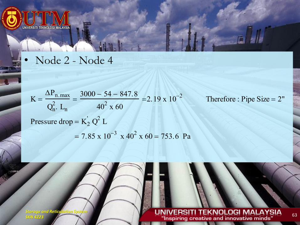
• Node 2 - Node 4
K Pn.max
Q2n. Ln
3000 54 847.8
402 x 60
2.19 x 10²
Therefore : Pipe Size 2"
Pressure drop K'2 Q
2 L
7.85 x 103
x 402 x 60 753.6 Pa

Storage and Reticulation System SKN 4223 64
• Node 1 - Node 5
K Pn.max
Q2n. Ln
3000 54.0
302 x 5
6.5 x 101
Therefore : Pipe Size 1"
Pressure drop K'2 Q
2 L
2.37 x 101
x 302 x 5 1066.5 Pa
Storage and Reticulation System SKN 4223 65
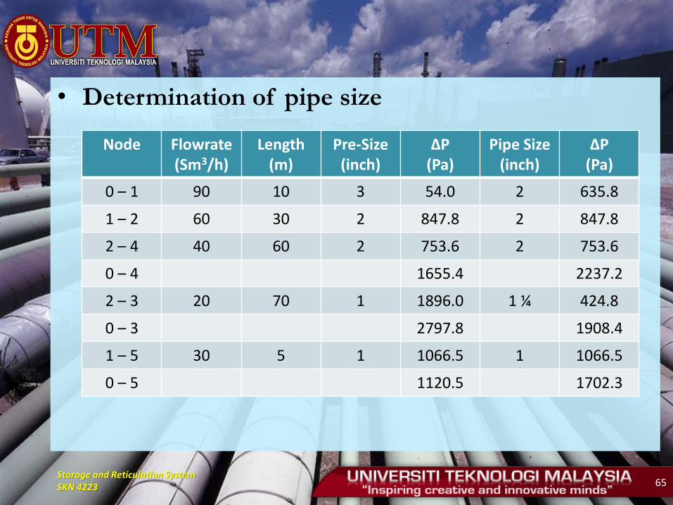
• Determination of pipe size
Node Flowrate (Sm3/h)
Length (m)
Pre-Size (inch)
ΔP (Pa)
Pipe Size (inch)
ΔP (Pa)
0 – 1 90 10 3 54.0 2 635.8
1 – 2 60 30 2 847.8 2 847.8
2 – 4 40 60 2 753.6 2 753.6
0 – 4 1655.4 2237.2
2 – 3 20 70 1 1896.0 1 ¼ 424.8
0 – 3 2797.8 1908.4
1 – 5 30 5 1 1066.5 1 1066.5
0 – 5 1120.5 1702.3
Storage and Reticulation System SKN 4223 66
NFPA 54
• Noted for simplicity
• Given a length and the maximum load, the required pipe size is read directly from the table
• Following factors are required.
1) Allowable loss in pressure from point of delivery to equipment
2) Maximum gas demand
3) Length of pipe from the point of delivery to the most remote
4) Specific gravity of gas
5) Diversity factor
Storage and Reticulation System SKN 4223 67
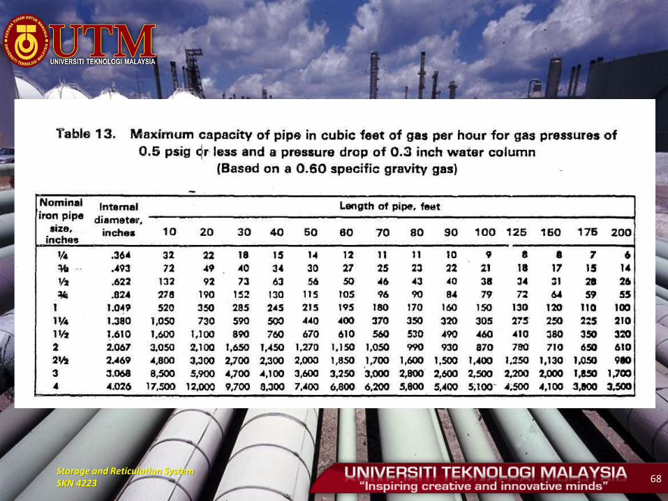
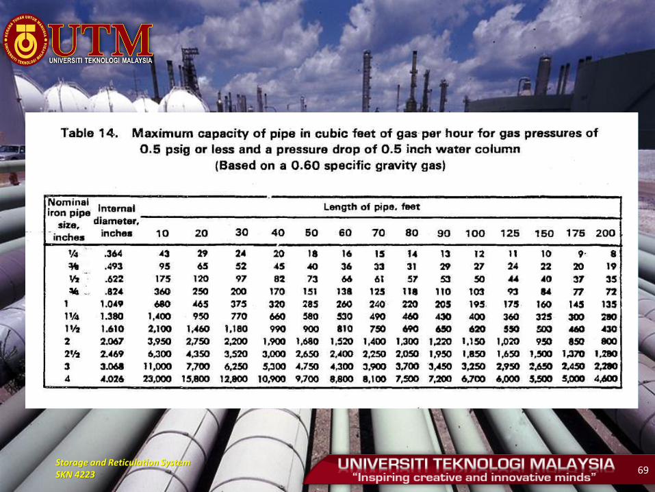
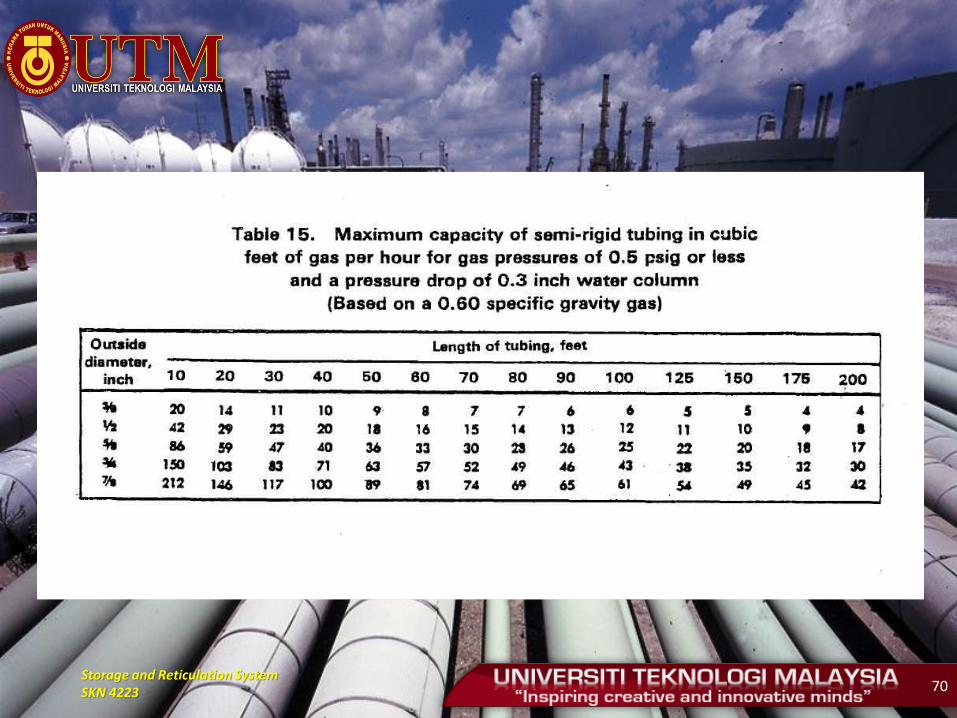
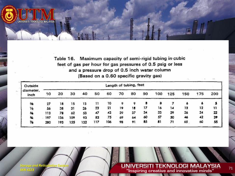
• Capacities for low pressure (0.5 psig or less) in cubic feet per hour of 0.60 specific gravity for different length are shown in Table 13 to Table 16 ( MS 930) for iron pipe or equivalent rigid pipe.
- Table 13 and 15 are based upon a pressure drop 0.3 inches water column
- Table 14 and 16 are based upon a pressure drop 0.5 inches water column
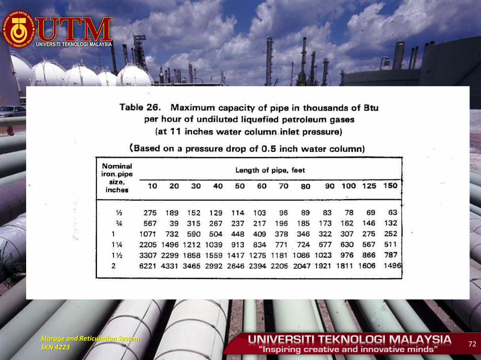
- Table 26 is used when capacities in thousands of BTU per hour of undiluted liquefied petroleum gases based on pressure drop 0.5 inches water column.
Storage and Reticulation System SKN 4223 68
Storage and Reticulation System SKN 4223 69
Storage and Reticulation System SKN 4223 70
Storage and Reticulation System SKN 4223 71
Storage and Reticulation System SKN 4223 72

Storage and Reticulation System SKN 4223 73
• If the data does not give the exact value, select the
column showing the next larger
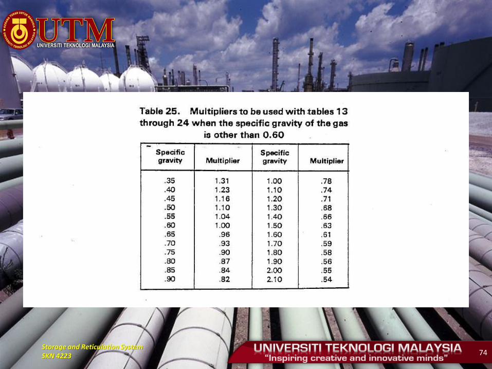
• If the gravity of gas is different with table 13 to 16,
use the gravity factor in Table 25
• In using these tables no additional allowance is
necessary for an ordinary number of fittings.
Storage and Reticulation System SKN 4223 74
Storage and Reticulation System SKN 4223 75
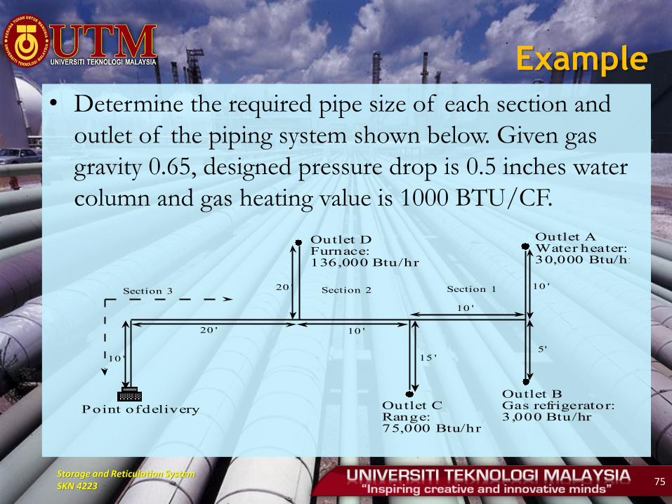
Example
• Determine the required pipe size of each section and
outlet of the piping system shown below. Given gas
gravity 0.65, designed pressure drop is 0.5 inches water
column and gas heating value is 1000 BTU/CF.
Point of delivery Outlet C Range: 75,000 Btu/hr
Outlet B Gas refrigerator: 3,000 Btu/hr
Outlet A Water heater: 30,000 Btu/hr
Outlet D Furnace: 136,000 Btu/hr
10 '
20 ' 10 '
15 '
20 '
10 '
10 '
5'
Section 3 Section 2 Section 1
Storage and Reticulation System SKN 4223 76
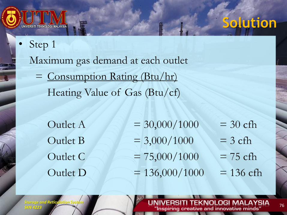
Solution
• Step 1
Maximum gas demand at each outlet
= Consumption Rating (Btu/hr)
Heating Value of Gas (Btu/cf)
Outlet A = 30,000/1000 = 30 cfh
Outlet B = 3,000/1000 = 3 cfh
Outlet C = 75,000/1000 = 75 cfh
Outlet D = 136,000/1000 = 136 cfh
Storage and Reticulation System SKN 4223 77
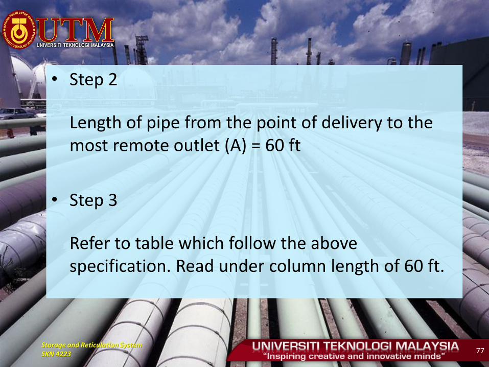
• Step 2
Length of pipe from the point of delivery to the most remote outlet (A) = 60 ft
• Step 3
Refer to table which follow the above specification. Read under column length of 60 ft.
Storage and Reticulation System SKN 4223 78
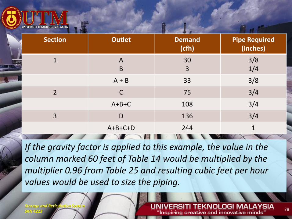
Section Outlet Demand (cfh)
Pipe Required (inches)
1 A B
30 3
3/8 1/4
A + B 33 3/8
2 C 75 3/4
A+B+C 108 3/4
3 D 136 3/4
A+B+C+D 244 1
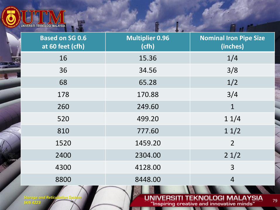
If the gravity factor is applied to this example, the value in the column marked 60 feet of Table 14 would be multiplied by the multiplier 0.96 from Table 25 and resulting cubic feet per hour values would be used to size the piping.
Storage and Reticulation System SKN 4223 79
Based on SG 0.6 at 60 feet (cfh)
Multiplier 0.96 (cfh)
Nominal Iron Pipe Size (inches)
16 15.36 1/4
36 34.56 3/8
68 65.28 1/2
178 170.88 3/4
260 249.60 1
520 499.20 1 1/4
810 777.60 1 1/2
1520 1459.20 2
2400 2304.00 2 1/2
4300 4128.00 3
8800 8448.00 4

Storage and Reticulation System SKN 4223 80
Clifford Method
• May not be simple but offers the advantage of
flexibility
• Can be noted with actual pressure drop and pipe
size
• Which ultimately may prove useful when making
adjustments for possible future loads.
• Classified by two categories
1) Low pressure line
2) High pressure line
Storage and Reticulation System SKN 4223 81
Low Pressure Line
• Five factors should be considered
i) Pipe length together with additional length of
fitting
ii) Allowable pressure drop
iii) Load or demand
iv) Pipe material
v) Actual pressure drop
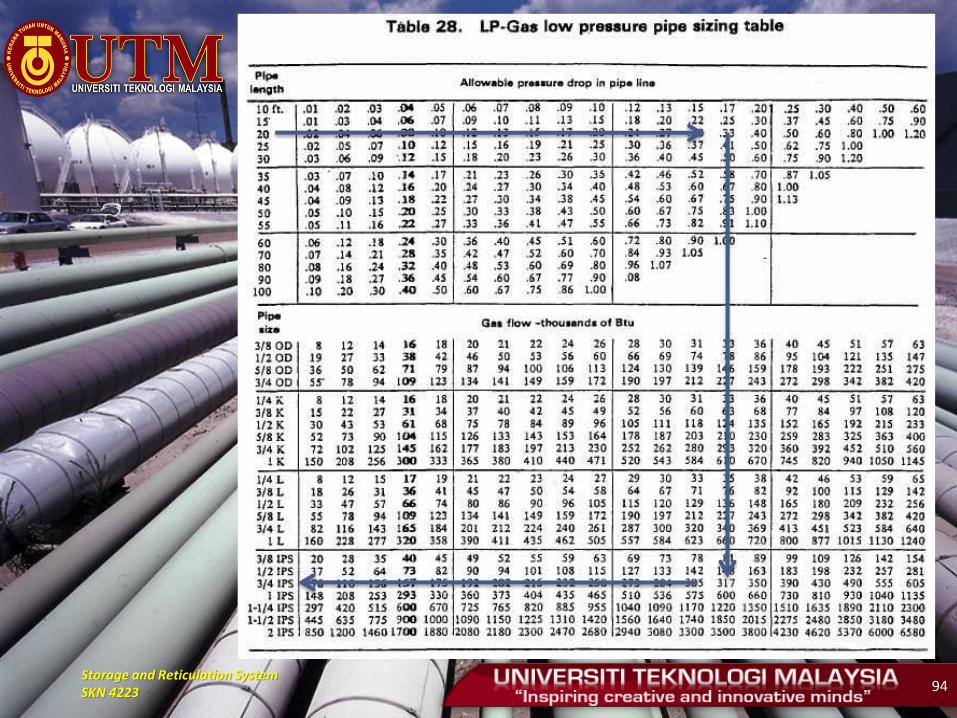
• Refer to Table 28 and Table 29

Storage and Reticulation System SKN 4223 82
Storage and Reticulation System SKN 4223 83
Storage and Reticulation System SKN 4223 84
Pipe Length
• Length 10 - 100 feet
Listed in left hand side of the table
• Length > 100 feet
The actual length (plus the allowable for fitting) and
allowable pressure drop are both divided by a
convenient number that will bring the pipe length
within the range of the table
Storage and Reticulation System SKN 4223 85
Example
• 280 ft line with allowable pressure drop 0.6 inches
water column.
• The pipeline would be properly sized if the length is
considered to be 70 (divided by 4) and the allowable
pressure drop is 0.15 inches water column.
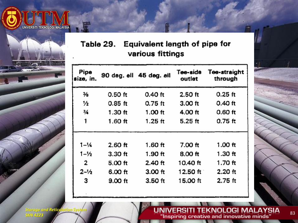
• Equivalent length for fitting refer to Table 29.
Commonly, 2 inches pipe size used as a reference. If
the final result (pressure drop) more than allowable
value select the next larger size.
Storage and Reticulation System SKN 4223 86
Allowable Pressure Drop
• Is given over to pressure drop ranging from 0.1 to
1.0 inches water column.
• This pressure drops makes the table quit flexible
and allow for appropriate selection.
• Allowable pressure drop used is 0.6 inches water
column.
• Single line pipeline is direct solving but branch
lines must be sized separately.
Storage and Reticulation System SKN 4223 87
Load or Demand
• Calculate the load it must handle.
• A branch line is sized on the basis of the BTU
rating of the appliance it services.
• The main line must handle the total load.
• An intermediate line will be sized for the
appliances it services.
Storage and Reticulation System SKN 4223 88
Pipe Material
• Four type of piping material system and practitioner
will make his selection on the basis of company
practice.
Actual Pressure Drop
• For the more complicated piping system it is helpful to
determine the actual pressure drop for the pipe sized
selected.

Storage and Reticulation System SKN 4223 89
Example
• Determine pipeline sizing of a domestic installation
shown below. Used allowable pressure drop is 0.6 inches
water column.
R
AB
C
D
15 feet, 0.34 " W C
5 feet,
0.26 " W C
10 feet, 0.26 " W C
10 feet,
0.26 " W C
Water h eater
30 ,0 00 Btu
Gas Rang e
63 ,0 00 Btu
Floo r furnace
80 ,0 00 Btu

Storage and Reticulation System SKN 4223 90
Solution
• Step 1
Leading to the appliance with the greatest load or input.
Equivalent length:
Main line
Measured length = 15 feet
One 90 degree elbow = 5 feet
Sub-Total = 20 feet
Branch line to floor furnace (The Greatest Load)
Measured length = 5 feet
Tee-Side Outlet = 10.4 feet
Sub-Total = 15.4 feet
Storage and Reticulation System SKN 4223 91
• Total pipe length from furnace to the pressure regulator is 35.4 feet
Since the main line is 0.57 of total length involved and 0.57 pressure drop of 0.6 inches water column is 0.34 inches water column. So allowable pressure drop on each branch line is 0.26 inches water column
Storage and Reticulation System SKN 4223 92
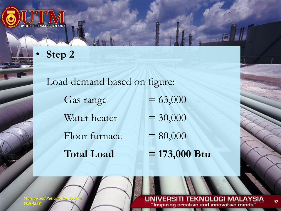
• Step 2
Load demand based on figure:
Gas range = 63,000
Water heater = 30,000
Floor furnace = 80,000
Total Load = 173,000 Btu
Storage and Reticulation System SKN 4223 93
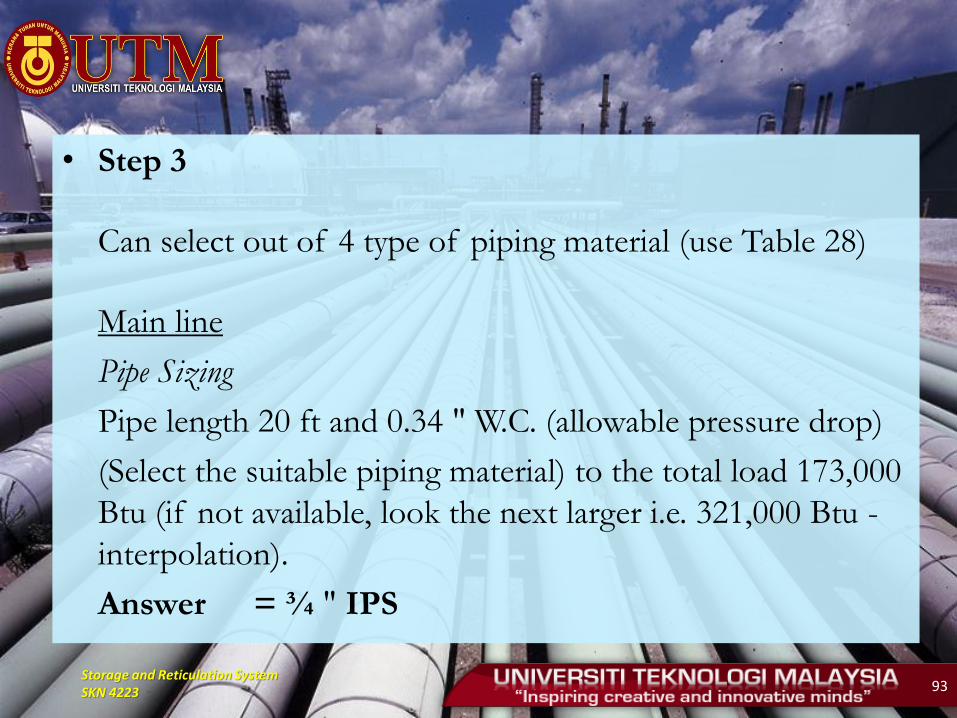
• Step 3
Can select out of 4 type of piping material (use Table 28)
Main line
Pipe Sizing
Pipe length 20 ft and 0.34 " W.C. (allowable pressure drop)
(Select the suitable piping material) to the total load 173,000
Btu (if not available, look the next larger i.e. 321,000 Btu -
interpolation).
Answer = ¾ " IPS
Storage and Reticulation System SKN 4223 94
Storage and Reticulation System SKN 4223 95
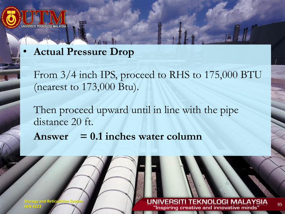
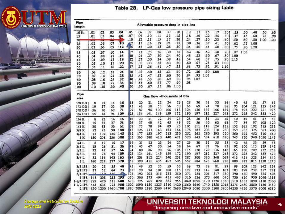
• Actual Pressure Drop
From 3/4 inch IPS, proceed to RHS to 175,000 BTU (nearest to 173,000 Btu).
Then proceed upward until in line with the pipe distance 20 ft.
Answer = 0.1 inches water column
Storage and Reticulation System SKN 4223 96
Storage and Reticulation System SKN 4223 97
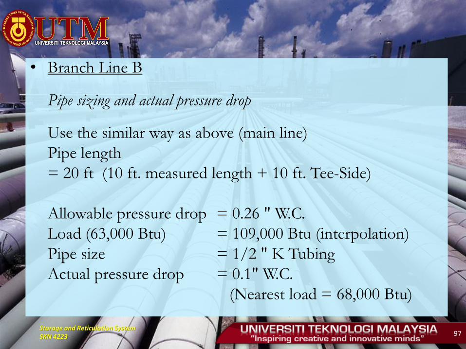
• Branch Line B
Pipe sizing and actual pressure drop
Use the similar way as above (main line)
Pipe length
= 20 ft (10 ft. measured length + 10 ft. Tee-Side)
Allowable pressure drop = 0.26 " W.C.
Load (63,000 Btu) = 109,000 Btu (interpolation)
Pipe size = 1/2 " K Tubing
Actual pressure drop = 0.1" W.C.
(Nearest load = 68,000 Btu)

Storage and Reticulation System SKN 4223 98
• Branch Line C Pipe sizing and actual pressure drop. Use the similar way as
above (main line). Pipe length = 20 ft (10 ft. measured length + 10 ft. Tee-Side) Allowable pressure drop = 0.26 " W.C. Load (30,000 Btu) = 54,000 Btu (interpolation) Pipe size = 3/8 " K Tubing Actual pressure drop = 0.08" W.C. (Nearest load = 31,000 Btu)

Storage and Reticulation System SKN 4223 99
• Branch Line D Pipe sizing and actual pressure drop. Use the similar way as
above (main line). Pipe length = 15 ft (5 ft. measured length + 10 ft. Tee-Side) Allowable pressure drop = 0.26 " W.C. Load (80,000 Btu) = 126,000 Btu (interpolation) Pipe size = 1/2 " K Tubing Actual pressure drop = 0.11" W.C. (Nearest load = 84,000 Btu)

Storage and Reticulation System SKN 4223 100
High Pressure Line
• If an appliance requires gas at a pressure of 10 psig or
15 psig for proper operation, it will have to supplied by
a high pressure gas line.
• The carrying capacity of a pipeline is 10 times or 15
times greater with high pressure gas than with low
pressure.
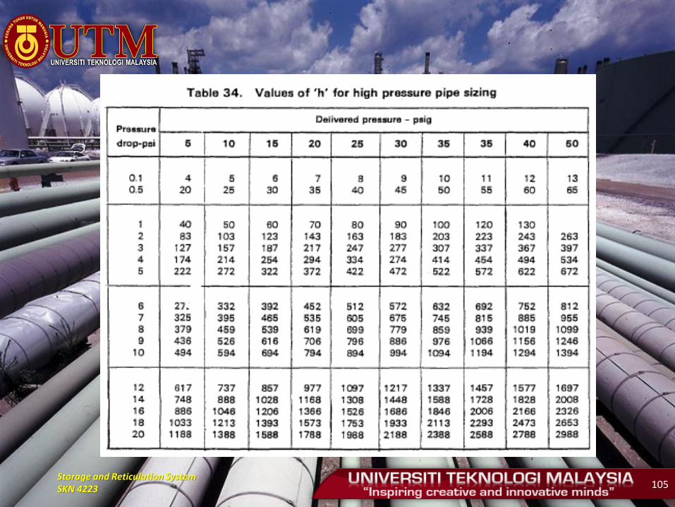
- Table 31 to Table 34 (MS 930) have to be used
for Option 1
- Chart in Figure 19 (MS 930) has to be used for
Option 2.
Storage and Reticulation System SKN 4223 101
• The increased capacity depends, of course on the
pressure at which the gas is piped and allowed pressure
drop.
• If an existing low pressure line has become overload, its
capacity may be increased considerably by increasing the
pressure by only a few pounds.
• In many such cases it would be less expensive and
provide better performance to change to two-stage
regulator rather than replace the existing low pressure
line.
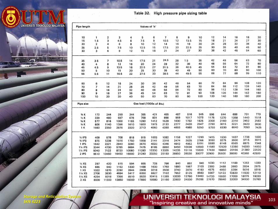
Storage and Reticulation System SKN 4223 102
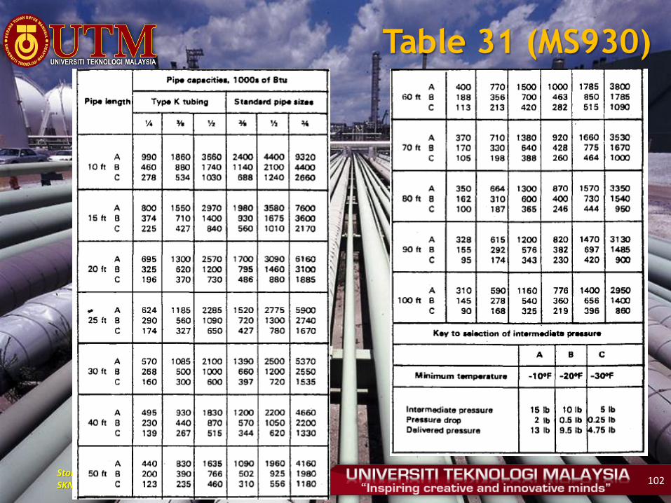
Table 31 (MS930)
Storage and Reticulation System SKN 4223 103

Storage and Reticulation System SKN 4223 104
Storage and Reticulation System SKN 4223 105
Storage and Reticulation System SKN 4223 106
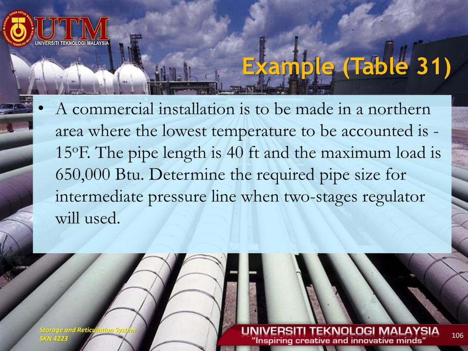
Example (Table 31)
• A commercial installation is to be made in a northern
area where the lowest temperature to be accounted is -
15oF. The pipe length is 40 ft and the maximum load is
650,000 Btu. Determine the required pipe size for
intermediate pressure line when two-stages regulator
will used.
Storage and Reticulation System SKN 4223 107
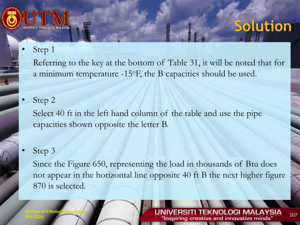
Solution
• Step 1
Referring to the key at the bottom of Table 31, it will be noted that for
a minimum temperature -15oF, the B capacities should be used.
• Step 2
Select 40 ft in the left hand column of the table and use the pipe
capacities shown opposite the letter B.
• Step 3
Since the Figure 650, representing the load in thousands of Btu does
not appear in the horizontal line opposite 40 ft B the next higher figure
870 is selected.

Storage and Reticulation System SKN 4223 108
• Step 4
Moving upward from the 870 just selected the required pipe size is found to be ½ inch type K tubing. By following the same procedure in the right of the table, ½ inch pipe will be indicated for this installation.
Note: For sizing high pressure lines involving factors beyond the scope of the simplified in Table 31, Table 32 to Table 35 are recommended.
Storage and Reticulation System SKN 4223 109
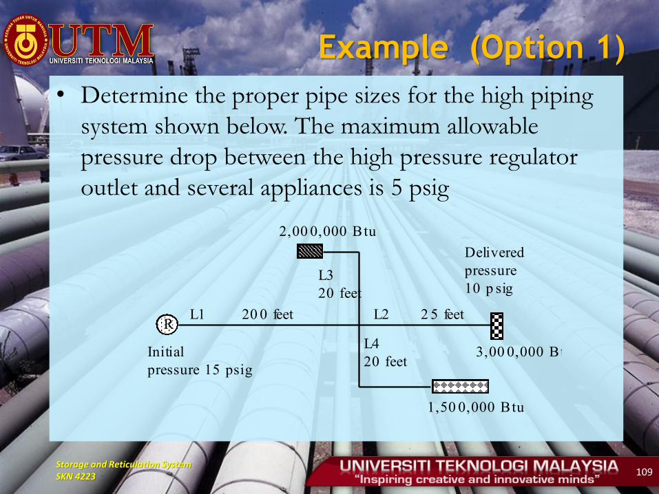
Example (Option 1)
• Determine the proper pipe sizes for the high piping
system shown below. The maximum allowable
pressure drop between the high pressure regulator
outlet and several appliances is 5 psig
RL1 20 0 feet
L4
20 feet
L2 2 5 feet
L3
20 feet
2,00 0,000 Btu
1,50 0,000 Btu
3,00 0,000 Btu
Delivered
pressure
10 p sig
Initial
pressure 15 psig
Storage and Reticulation System SKN 4223 110
• Step 1
An arbitrary decision must be made as to how this will be apportioned.
Suggested:
Main line = 3 psi
Each branch = 2 psi
Therefore, delivered pressure for the main line will be 12 psi and this will then be the initial pressure for the branch lines.

Storage and Reticulation System SKN 4223 111
• Step 2
Referring to Table 33.
15 psi initial pressure it will be seen that the value of 'h' for 3 psi pressure drop is 169.
For each branch lines the initial is 12 psi and the pressure drop is 2 psi. For this pressure drop and initial pressure the value of 'h' is 103
Storage and Reticulation System SKN 4223 112
• Step 3 Size the main line Pipe length = 200 ft Value of 'h' = 169 Load = 6500 thousand Btu (total load) Since 200 ft is not shown in the pipe sizing table. It is necessary to make
adjustment such as the following: 200 ft value of 'h' 169 100 ft value of 'h' 85 In table 32, the values 80 and 90 are found for 'h'. Since 85 is haft way
between, one can follow down between the two line to the standard pipe section.
The indicated pipe sized = 1 1/4 IPS
Storage and Reticulation System SKN 4223 113
• However, the actual value of 'h' can be estimated.
Find 6500 in the horizontal line opposite to 1 ¼
IPS: 6684 is selected
• Proceed upward to the 100 ft line it is seen that the
actual value of 'h' appears to be 40. Since pipe
length and 'h' were divided by 2, it is necessary now
multiply by 2 to get the true value of 'h' for the size
selected.
Storage and Reticulation System SKN 4223 114
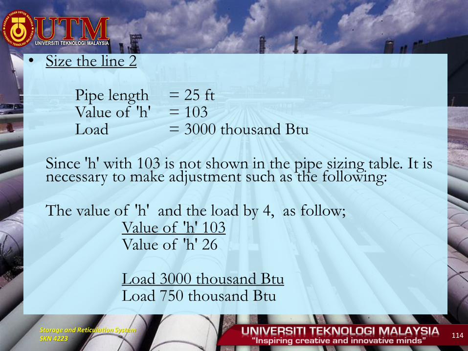
• Size the line 2 Pipe length = 25 ft Value of 'h' = 103 Load = 3000 thousand Btu Since 'h' with 103 is not shown in the pipe sizing table. It is
necessary to make adjustment such as the following: The value of 'h' and the load by 4, as follow; Value of 'h' 103 Value of 'h' 26 Load 3000 thousand Btu Load 750 thousand Btu
Storage and Reticulation System SKN 4223 115
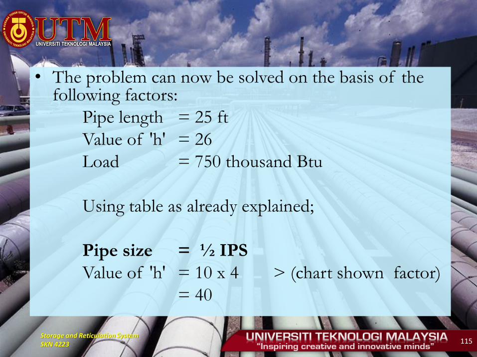
• The problem can now be solved on the basis of the following factors:
Pipe length = 25 ft
Value of 'h' = 26
Load = 750 thousand Btu
Using table as already explained;
Pipe size = ½ IPS
Value of 'h' = 10 x 4 > (chart shown factor)
= 40
Storage and Reticulation System SKN 4223 116
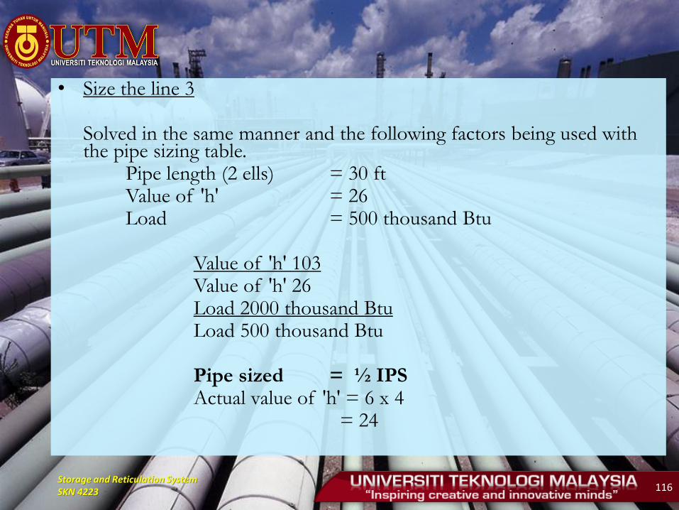
• Size the line 3 Solved in the same manner and the following factors being used with
the pipe sizing table. Pipe length (2 ells) = 30 ft Value of 'h' = 26 Load = 500 thousand Btu Value of 'h' 103 Value of 'h' 26 Load 2000 thousand Btu Load 500 thousand Btu Pipe sized = ½ IPS Actual value of 'h' = 6 x 4 = 24
Storage and Reticulation System SKN 4223 117
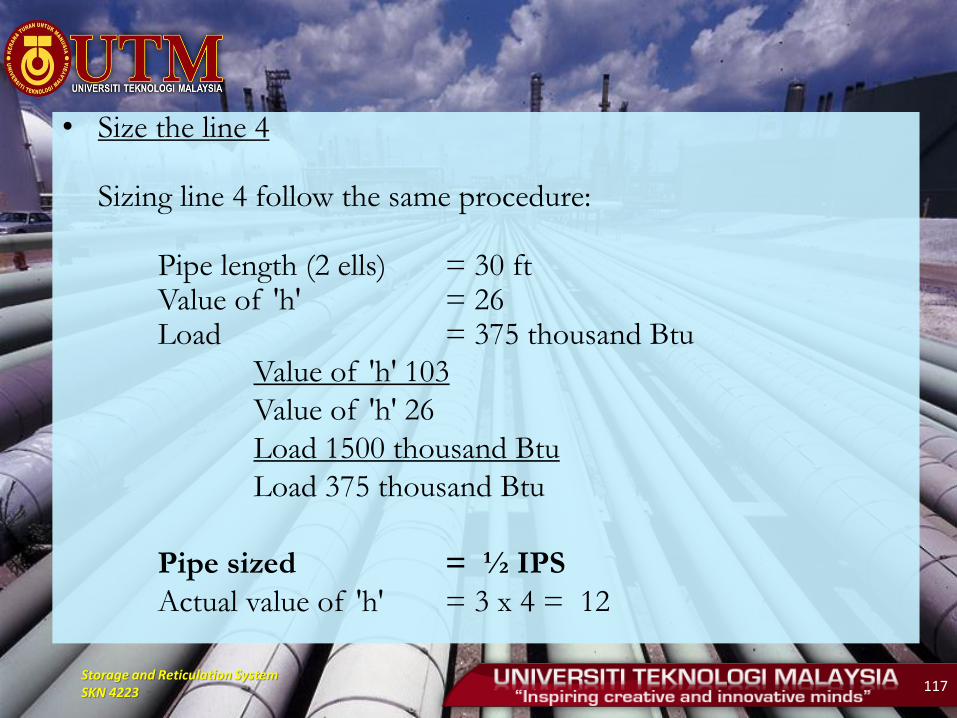
• Size the line 4 Sizing line 4 follow the same procedure: Pipe length (2 ells) = 30 ft Value of 'h' = 26 Load = 375 thousand Btu
Value of 'h' 103
Value of 'h' 26
Load 1500 thousand Btu
Load 375 thousand Btu
Pipe sized = ½ IPS
Actual value of 'h' = 3 x 4 = 12

Storage and Reticulation System SKN 4223 118
Example (Option 2)
• Find the proper size of standard weight pipe for a
1000 ft line which is to carry a load of 10,000,000
Btu/h. The initial pressure is 20 psi and the pressure
drop is limited to 3 psi.

Storage and Reticulation System SKN 4223 119
Storage and Reticulation System SKN 4223 120
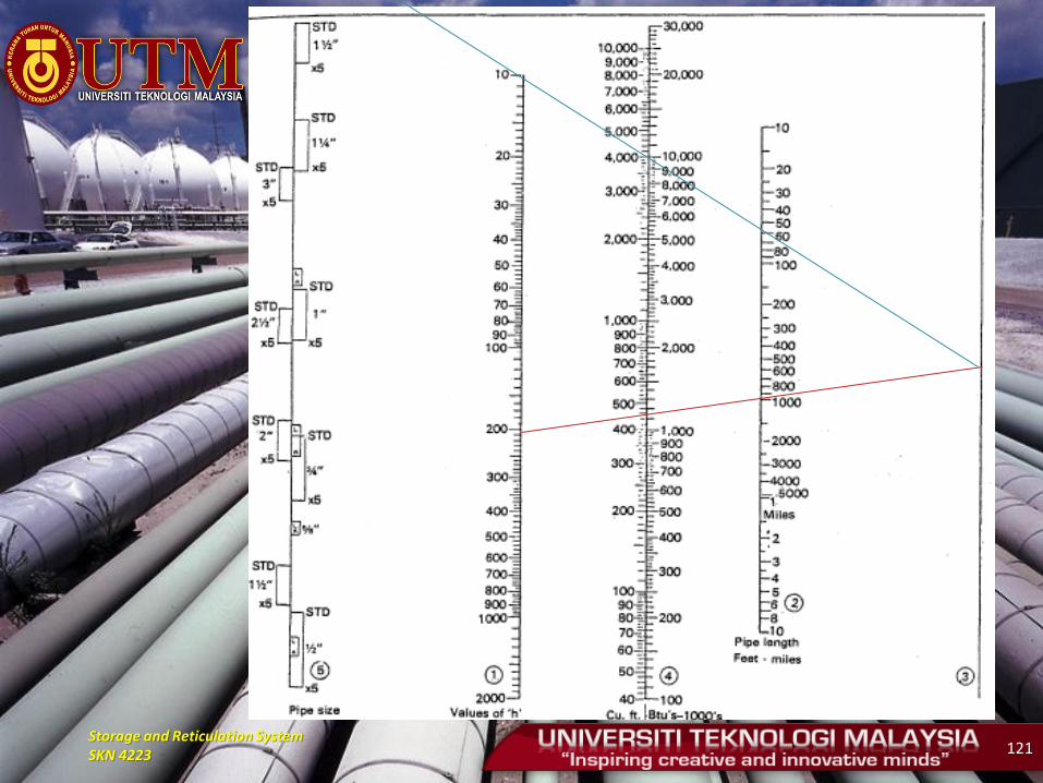
Solution
• Step 1
Refer to table 33 : h = 199
Use Figure 19.
Align this point on Figure 19 with 1000 ft and extending to Line 3.
• Step 2
Align point on Line 3 with 10,000 of Scale 4 and extend to Scale 5. However, no pipe size can be read because out of range (no intersection).
Storage and Reticulation System SKN 4223 121
Storage and Reticulation System SKN 4223 122
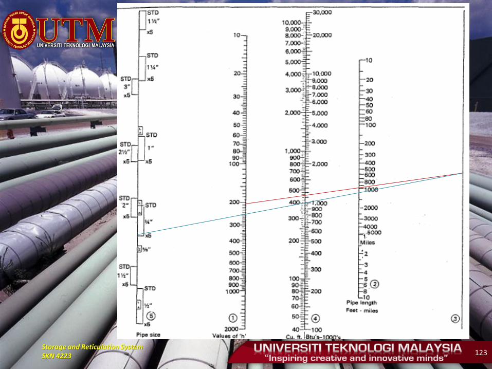
• Step 3
Divide the 10,000 thousand Btu by 10 and repeat Step 2.
Pipe size in between 1 ½ " and 2 "
Answer: Select pipe size with 2 "
Storage and Reticulation System SKN 4223 123

Storage and Reticulation System SKN 4223 124
• Step 4
To find actual pressure drop with pipe size selected, reversed the above procedure.
Start with 2" pipe size.
Answer :
h value = 110
pressure drop in between 1 ½ psi and 2 psi.

Storage and Reticulation System SKN 4223 125

Storage and Reticulation System SKN 4223 126
BUOYANCY CONTROL
• Pipeline are subject to buoyant forces when they
encounter free-standing or flowing water at river
crossing, streams and lakes and when buried in the
saturated soils generally present in flood plains,
marshes, swamps, muskeg (bogs) and local depressions.
Storage and Reticulation System SKN 4223 127
• There are two principles reasons for counteracting the buoyant force exerted on a pipeline system:
i) to submerge the pipe in a water-filled ditch during construction prior to backfilling
ii) to prevent the pipe from floating or rising off at the ditch bottom during the post installation period and during operation of the pipeline.

Storage and Reticulation System SKN 4223 128
• Potential areas requiring buoyancy control can be classified into four brad categories:
i) river crossings
ii) stream or creek crossings
iii) muskeg or bogs crossing
iv) soil which have the potential to act as a fluid
Storage and Reticulation System SKN 4223 129
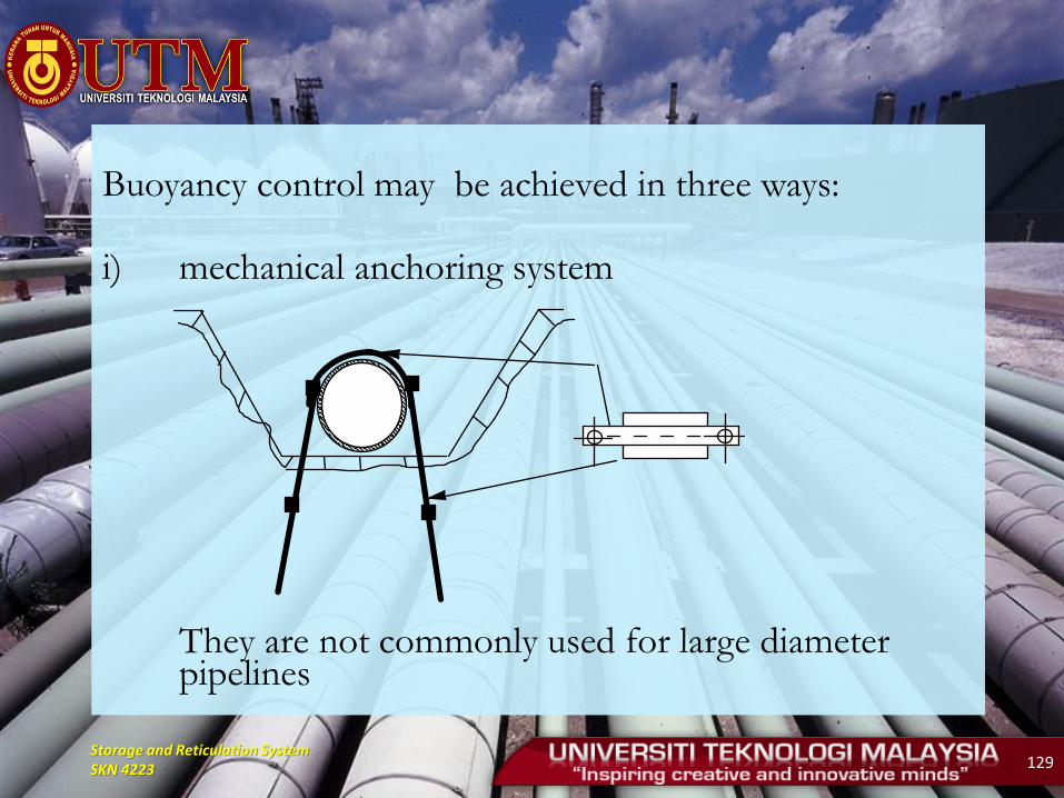
Buoyancy control may be achieved in three ways: i) mechanical anchoring system
They are not commonly used for large diameter pipelines
Storage and Reticulation System SKN 4223 130
ii) Backfill
• Using either native or borrowed material for buoyancy control, relies on the mass of the backfill over the pipe to counteract the buoyancy forces.
• Native backfill may be considered if it consists of stable, ice-free soil which is capable of achieving a reasonable level of strength.
• If the native backfill is not adequate, select backfill can be used. Select backfill should be coarse-grained, free draining material exhibiting sufficient shear strength when thawed or mixed with water.
• Although gravel is undoubtedly the best material, other materials such as a mixture of gravel, sand, clay and silt can be used
Storage and Reticulation System SKN 4223 131
iii) density anchoring system
Density anchors are a system of weight added to the pipeline.
The types of anchors usually in the form of concrete are
1. swamp weights (saddle or set-on weights)
2. river weights (bolt-on)
3. continues concrete coating.
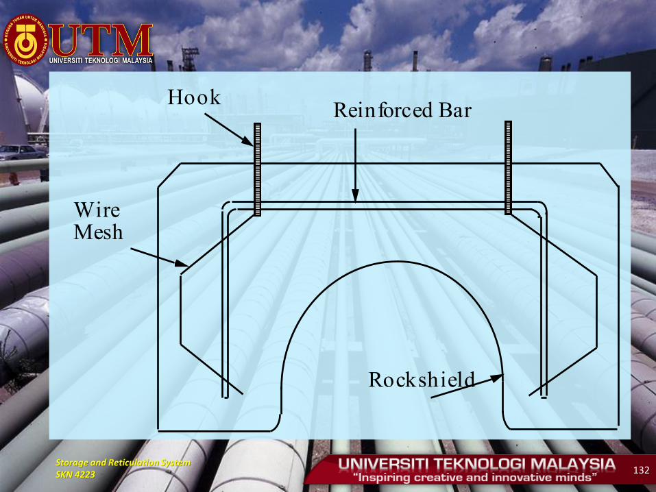
Storage and Reticulation System SKN 4223 132
HookReinforced Bar
Wire Mesh
Rockshield
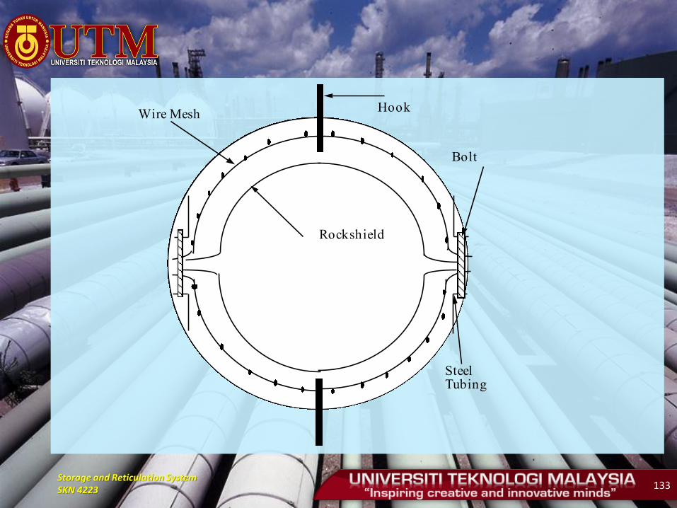
Storage and Reticulation System SKN 4223 133
Hook
Rockshield
Wire Mesh
Bolt
Steel Tubing
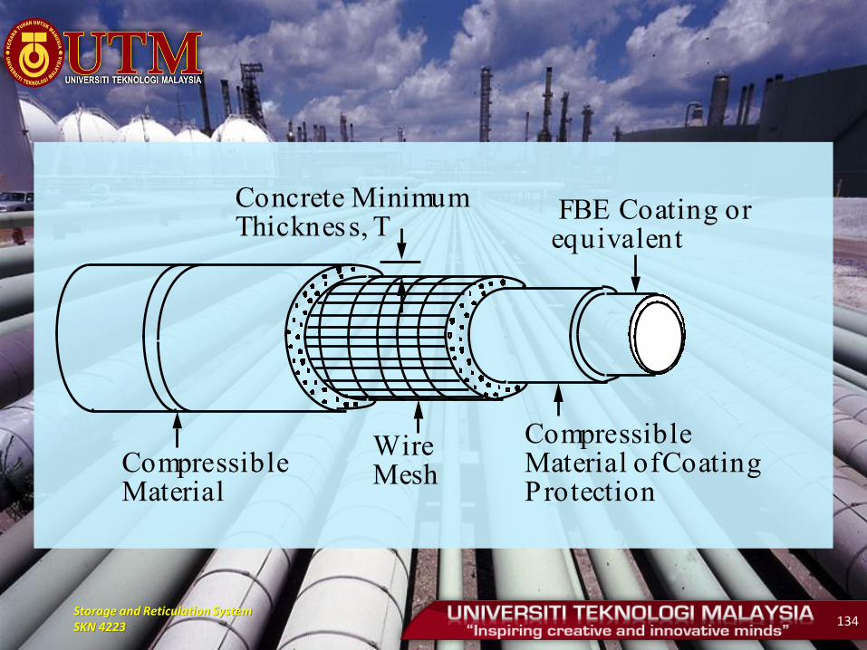
Storage and Reticulation System SKN 4223 134
Concrete Minimum Thickness, T
FBE Coating or equivalent
Compressible Material of Coating Protection
Wire MeshCompressible
Material
Storage and Reticulation System SKN 4223 135
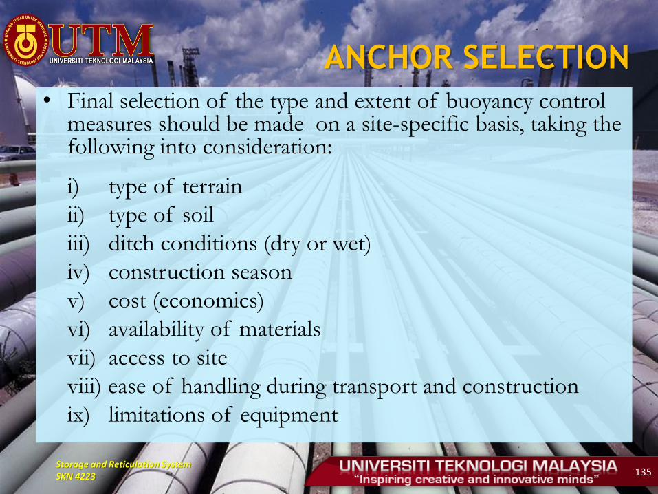
ANCHOR SELECTION
• Final selection of the type and extent of buoyancy control measures should be made on a site-specific basis, taking the following into consideration:
i) type of terrain
ii) type of soil
iii) ditch conditions (dry or wet)
iv) construction season
v) cost (economics)
vi) availability of materials
vii) access to site
viii) ease of handling during transport and construction
ix) limitations of equipment

Storage and Reticulation System SKN 4223 136
ANCHOR DESIGN
CONSIDERATION
• In general, design of buoyancy control system are based on location conditions. For example, the following values or factors are incorporated into design calculation in Canada:
i) For river flood plains, small streams, drainage course, swamp, muskeg, small lakes and local depression where water will be encountered in the ditch during construction:
Negative Buoyancy : 5%
Fluid Density : 1040 kg/m3
Storage and Reticulation System SKN 4223 137
• For main river channels and areas where flowing or moving water will be encountered during construction:
Negative Buoyancy : 10 %
Fluid Density : 1000 kg/m3
Storage and Reticulation System SKN 4223 138
• However, in Malaysia design of buoyancy
control system is constant which is based on
negative buoyancy as 20 percent in all conditions
and density of fluid is 1000 kg/m3.
Storage and Reticulation System SKN 4223 139
PIPELINE TESTING
• Pipeline testing required if the pipeline operates at
Hoop Stress of more than 30% of SMYS.
• Required to ensure that all connections are sealed and
without expansion
• performed after completion of installation activities
except tie-in part or the location of the testing is not
appropriate.
• Required by all code-gas code of practice
• It should be witnessed by the local gas inspector to
make verification

Storage and Reticulation System SKN 4223 140
• There are two types of pipeline tests carried out
1. Hydrostatic test - test medium: water or methanol
2. Pneumatic test - test medium: compressed air or
inert gas
• Test pressure must be higher than the maximum
operating pressure and is usually 1.5 times the
design pressure.
Storage and Reticulation System SKN 4223 141
• An important aspect of any operational testing is complete and accurate documentation - records remain as long as the equipment or piping is used.
• According to the Federal Pipeline Safety Regulations, USA, records must have the following information:
1. Pressure record chart 2. Equipment calibration test data 3. Name of the responsible operator 4. Date and time of test 5. Testing pressure 6. Testing medium 7. Description of testing equipment 8. Comments
Storage and Reticulation System SKN 4223 142
HYDROSTATIC TEST
• General Guideline- Testing Part
1. Pipe Length < 16 km
2. For testing medium other than water, testing
capacity lower than 500 m3.
3. Determination of low and high pints, and testing
pressure.
4. Pipe ends nearby water resources are preferred.
5. All parts tested with equal diameter and pressure.

Storage and Reticulation System SKN 4223 143
Hydrostatic Test Calculation
• Using standard forms and determination of the
required pressure test involving:
1. Location of the test
2. Pipe dimension
3. Low and high pints, and testing pressure.
4. Grade or pipe SMYS
5. Maximum operating pressure
Storage and Reticulation System SKN 4223 144
Preparation before the
Performing Test
• Step 1: Approval to pump the water, if necessary
• Step 2: Testing Equipments:
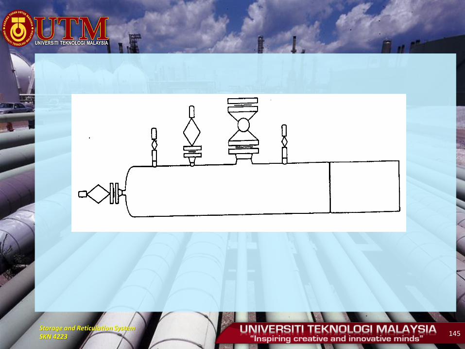
a) Pressure and temperature recorder
b) Test head
c) Dead Weight Tester
d) Pressure and temperature gauge, if necessary
e) Flowmeter
f) Fittings - used to connect all equipment
Storage and Reticulation System SKN 4223 145
Storage and Reticulation System SKN 4223 146
• Step 3: Water filling
a) Water must not containing mud, floating materials or corrosive components unless it can be removed or treated.
b) The filling made with poly pig (front) or coated form pig.
c) Avoid air trapped in the pipeline - Will affect the testing process - Hazardous conditions
d) Check the head to prevent leakage test after completing the filling of water
Storage and Reticulation System SKN 4223 147
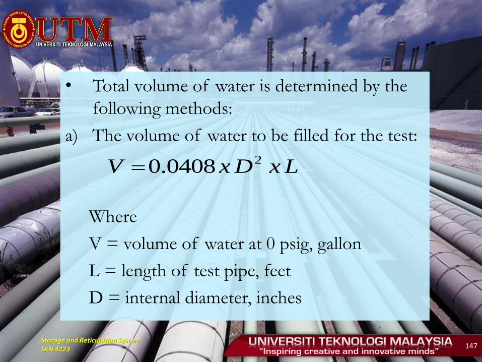
• Total volume of water is determined by the
following methods:
a) The volume of water to be filled for the test:
Where
V = volume of water at 0 psig, gallon
L = length of test pipe, feet
D = internal diameter, inches
LxDxV 20408.0
Storage and Reticulation System SKN 4223 148
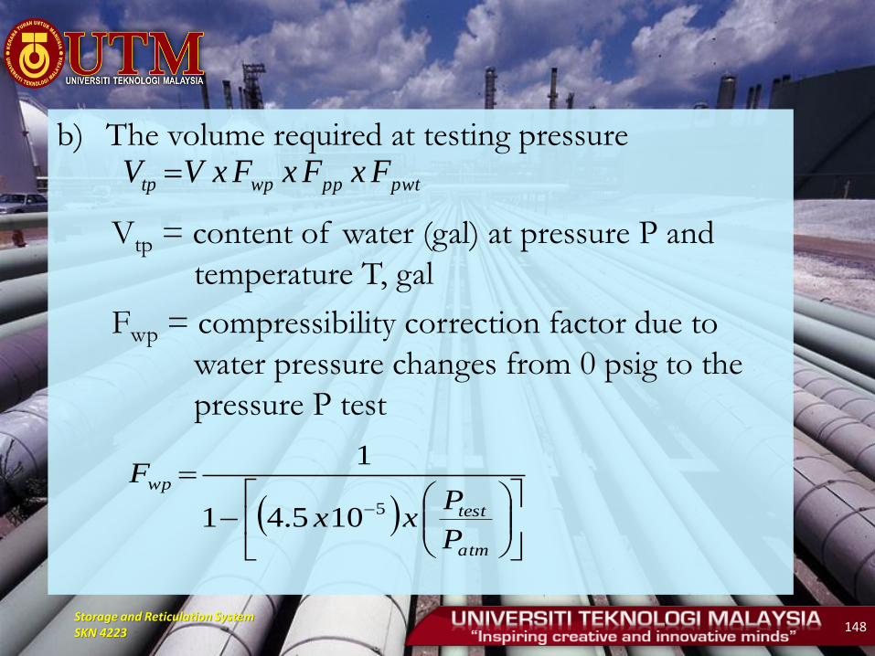
b) The volume required at testing pressure
Vtp = content of water (gal) at pressure P and
temperature T, gal
Fwp = compressibility correction factor due to
water pressure changes from 0 psig to the
pressure P test
pwtppwptp FxFxFxVV
atm
test
wp
P
Pxx
F5105.41
1
Storage and Reticulation System SKN 4223 149
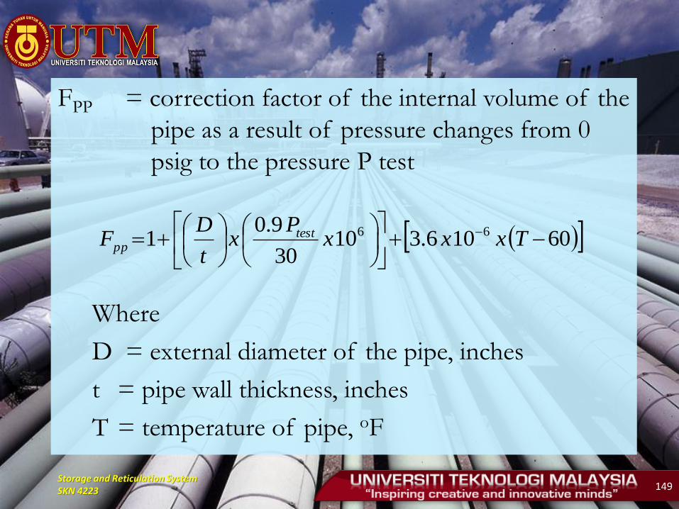
FPP = correction factor of the internal volume of the
pipe as a result of pressure changes from 0
psig to the pressure P test
Where
D = external diameter of the pipe, inches
t = pipe wall thickness, inches
T = temperature of pipe, oF
60106.31030
9.01 66
Txxx
Px
t
DF test
pp
Storage and Reticulation System SKN 4223 150
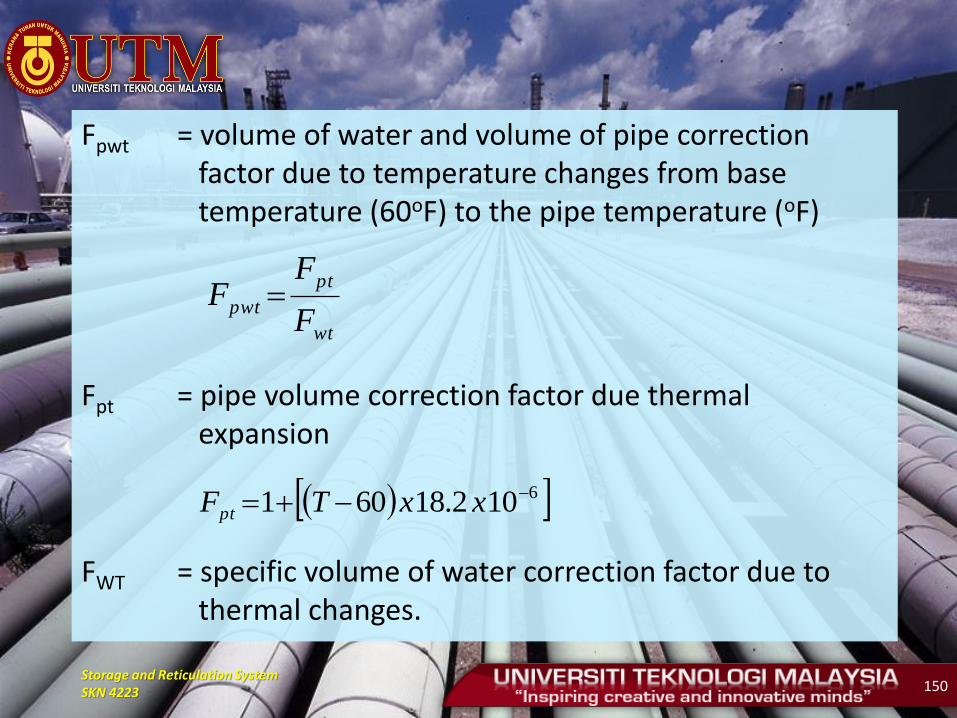
Fpwt = volume of water and volume of pipe correction factor due to temperature changes from base temperature (60oF) to the pipe temperature (oF)
Fpt = pipe volume correction factor due thermal expansion
FWT = specific volume of water correction factor due to thermal changes.
wt
pt
pwtF
FF
6102.18601 xxTFpt
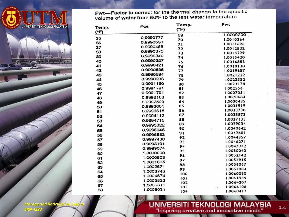
Storage and Reticulation System SKN 4223 151

Storage and Reticulation System SKN 4223 152
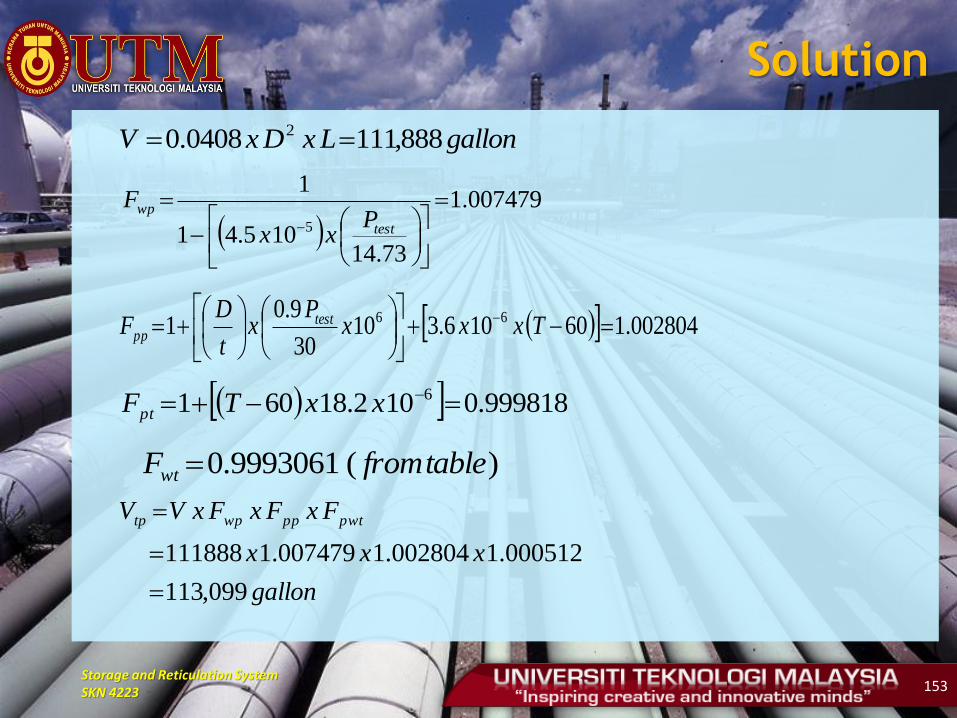
Example 1
• Calculate the volume of water required
during the filling and pressure testing
Pipe Size: 10.75 inch OD x 0.279 w.t. X52
Length: 5 miles (5280 feet = 1 mile)
Test Pressure: 2430 psig
Temperature: 50oF
Storage and Reticulation System SKN 4223 153
Solution
gallonLxDxV 888,1110408.0 2
007479.1
73.14105.41
1
5
test
wpP
xx
F
002804.160106.31030
9.01 66
Txxx
Px
t
DF test
pp
999818.0102.18601 6 xxTFpt
)(9993061.0 tablefromFwt
gallon
xxx
FxFxFxVV pwtppwptp
099,113
000512.1002804.1007479.1111888
Storage and Reticulation System SKN 4223 154
Example 2
• After some time, testing pressure P was reduced to
2422 psig and temperature of the water and pipe
has been reduced to 48oF. Determine the volume
of testing at the time.

Storage and Reticulation System SKN 4223 155
Solution
000565.1
999217.0
999781.0
002796.1
007454.1
48
2422
888,111
1
1
1
1
1
1
1
pwt
wt
pt
pp
wp
o
F
F
F
F
F
FT
psigP
gallonV
gallon
xxx
FxFxFxVV pwtppwptp
101,113
000565.1002796.1007454.1111888
1
Storage and Reticulation System SKN 4223 156
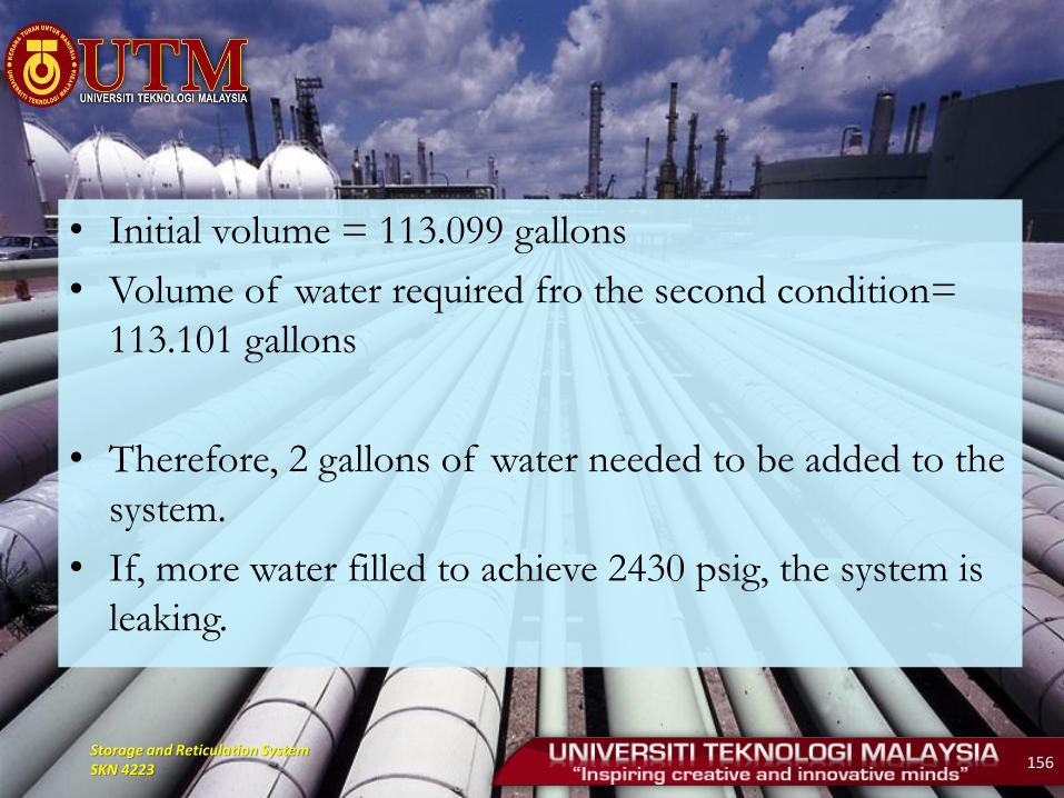
• Initial volume = 113.099 gallons
• Volume of water required fro the second condition=
113.101 gallons
• Therefore, 2 gallons of water needed to be added to the
system.
• If, more water filled to achieve 2430 psig, the system is
leaking.
Storage and Reticulation System SKN 4223 157
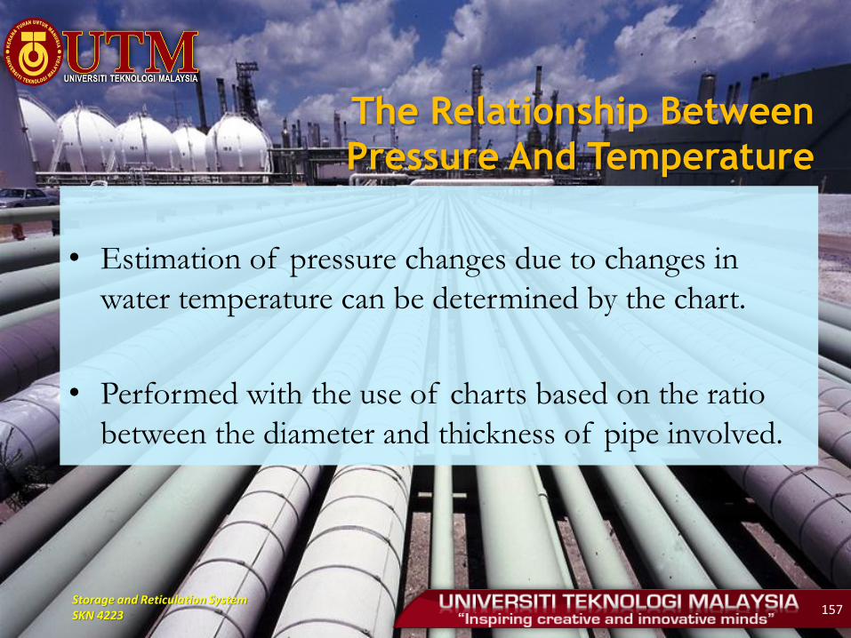
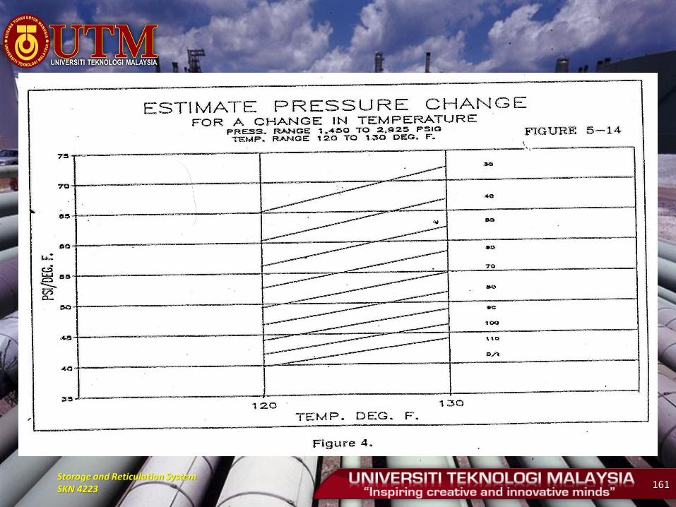
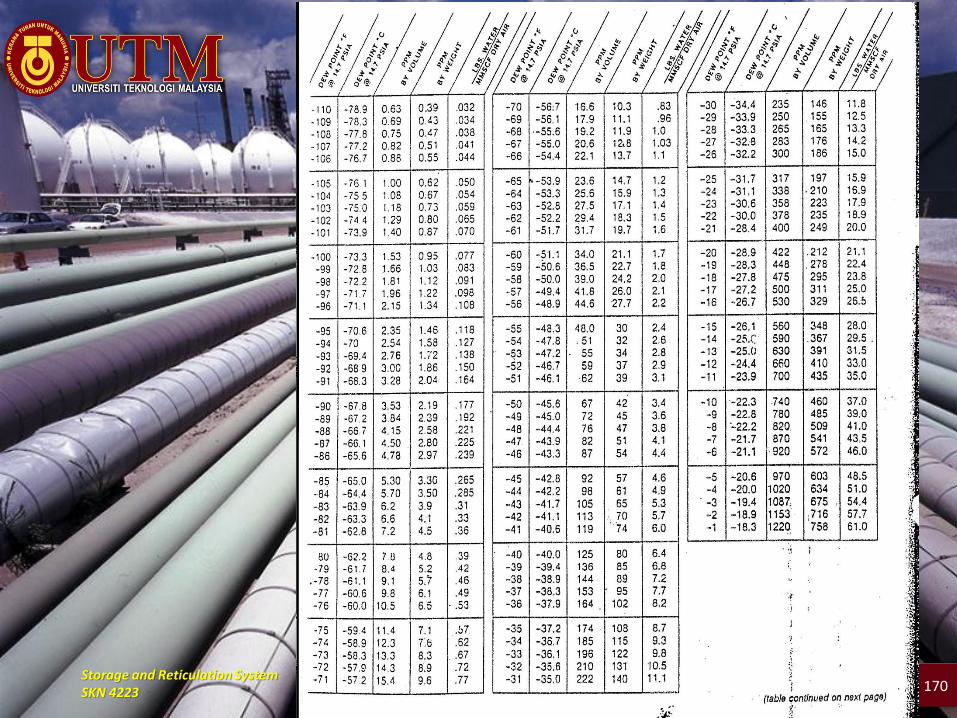
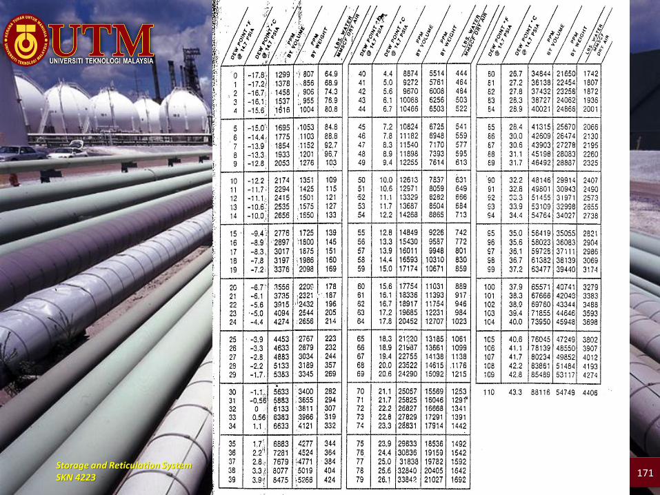
The Relationship Between
Pressure And Temperature
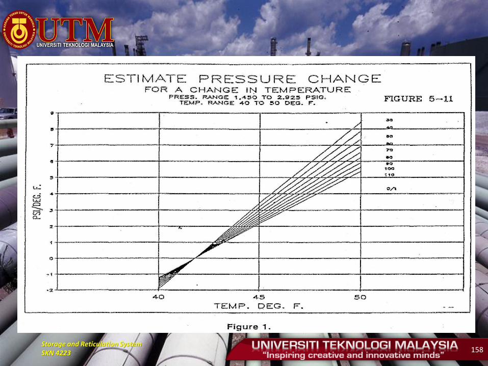
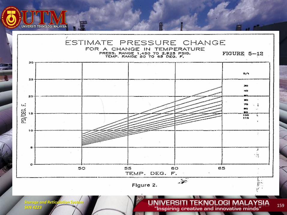
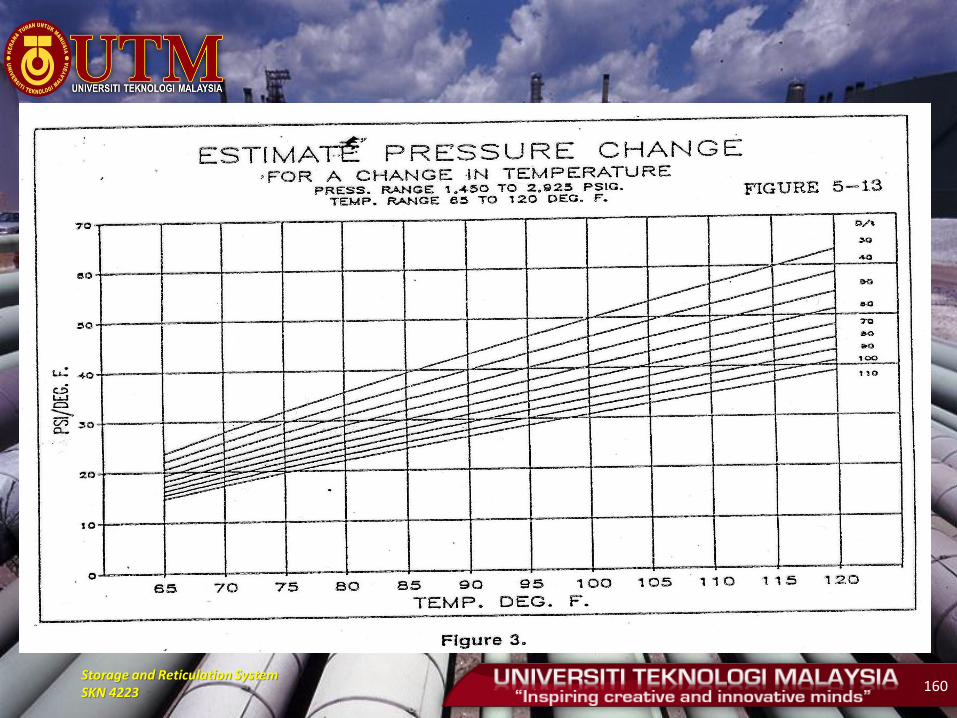
• Estimation of pressure changes due to changes in
water temperature can be determined by the chart.
• Performed with the use of charts based on the ratio
between the diameter and thickness of pipe involved.
Storage and Reticulation System SKN 4223 158
Storage and Reticulation System SKN 4223 159
Storage and Reticulation System SKN 4223 160
Storage and Reticulation System SKN 4223 161
Storage and Reticulation System SKN 4223 162
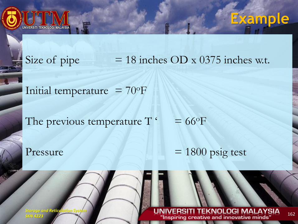
Example
Size of pipe = 18 inches OD x 0375 inches w.t.
Initial temperature = 70oF
The previous temperature T ‘ = 66oF
Pressure = 1800 psig test
Storage and Reticulation System SKN 4223 163
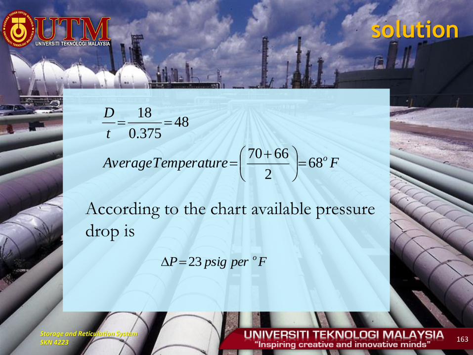
solution
According to the chart available pressure
drop is
FeTemperaturAverage
t
D
o682
6670
48375.0
18
FperpsigP o23
Storage and Reticulation System SKN 4223 164
• Step 4: Pressuring
• Pressuring - typically use reciprocating pumps up
the pressure leak test
• The calculation of pressure tests should consider
the actual height in the area
• Pump stopped when the pressure reaches the leak
test pressure for a minimum of 30 minutes (time
stability of the pressure wave)
• Visually - check all the connectors

Storage and Reticulation System SKN 4223 165
• Step 5: Test 24 hours (unless specified by the authorities involved)
• Pump to started to increase pressure to test pressure
• If the pressure falls more than 70 kPa within two hours, it must be re-pressurised
• Pressure is released through the test head when the pressure exceeds the test pressure.
• 24 hours started after the pump is removed from the pipe system
• Pressure and temperature recorded for 36 hours 1. Pressure increment 2. Leak testing 3. Period of stability 4. Test within 24 hours (methanol only six hours required) 5. Pressure reduction
Storage and Reticulation System SKN 4223 166
• Step 6: Pressure reduction
• Performed after the completion of the test.
• Pressure reduced to a maximum of 2000 kPa for
pipes with a diameter of 60.3 mm or more in
order to avoid the effects of vibration - broken
pipe
• Water drained away from the pipeline trench.
Storage and Reticulation System SKN 4223 167
• Step 7: Water Draining
• Water can be transferred to next part for testing
(if necessary) or be drained to suitable location.
• Compressor and poly pig usually used
simultaneously for draining.
• Step 8: Drying operation
• Pig launched (to remove water from the system)
• Pig moved at optimum velocity to remove
maximum volume of contaminants.
• This step repeated until satisfied.
Storage and Reticulation System SKN 4223 168
• Step 9: Methanol Cleaning
• Methanol used to improve water draining from pipe.
• This step performed after water draining and drying operation step.
• Below dew point (methanol help combating hydrate formation).
• Methanol filled between two pigs.
• Volume of methanol needed is about 15% of water volume.
• Maximum pipe length is 30 km – depending on methanol availability.
• Methanol must be ensure do not contacted with soil and not be drained to ground (it must be stored in suitable container to be reused)
Storage and Reticulation System SKN 4223 169
• Step 19: Air drying
• An alternative to methanol cleaning process
• Can be considered if one of the following
conditions happens:
– Existence of wet gas
– Reasonable cost to replace methanol drying
• Moisture content determined periodically at output
using dew point test (Mirror Hydrometer).
• Satisfied when dew point reach -45oC or lower.
Storage and Reticulation System SKN 4223 170
Storage and Reticulation System SKN 4223 171
Storage and Reticulation System SKN 4223 172
PNEUMATIC TEST
• Usually performed by using compressed air
which relatively low cost.
• In certain condition, for safety reasons, inert
gas (in cylinder) should be considered.
Storage and Reticulation System SKN 4223 173
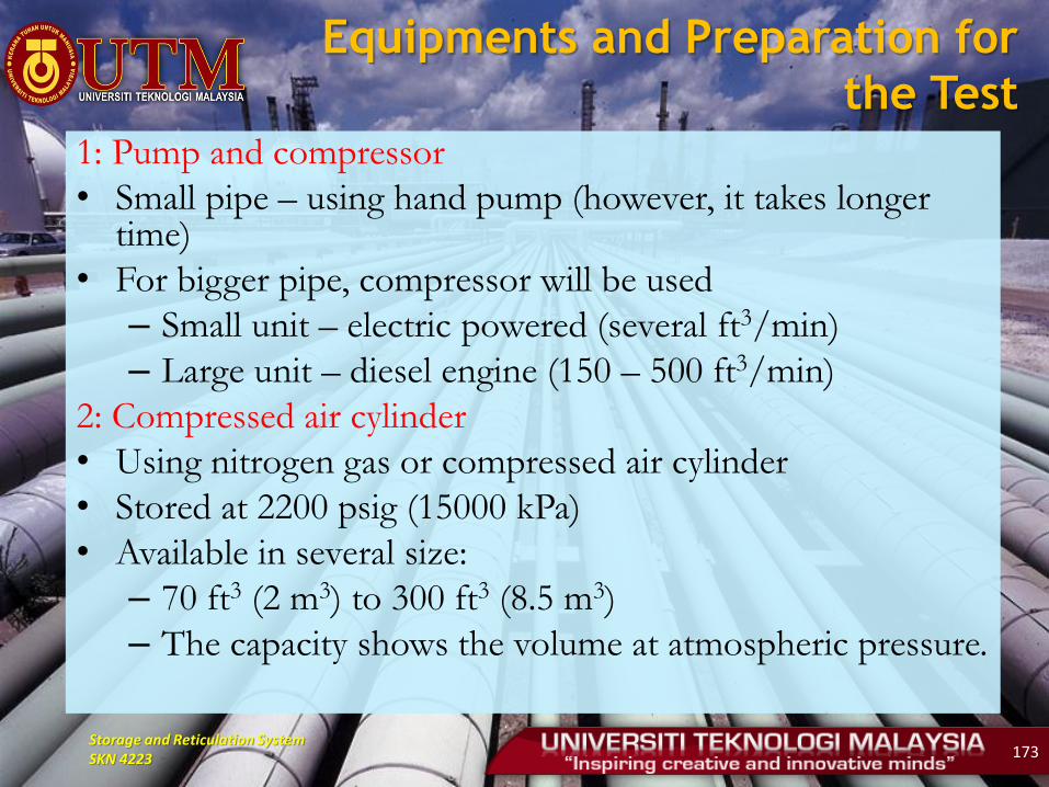
Equipments and Preparation for
the Test 1: Pump and compressor
• Small pipe – using hand pump (however, it takes longer time)
• For bigger pipe, compressor will be used
– Small unit – electric powered (several ft3/min)
– Large unit – diesel engine (150 – 500 ft3/min)
2: Compressed air cylinder
• Using nitrogen gas or compressed air cylinder
• Stored at 2200 psig (15000 kPa)
• Available in several size:
– 70 ft3 (2 m3) to 300 ft3 (8.5 m3)
– The capacity shows the volume at atmospheric pressure.
Storage and Reticulation System SKN 4223 174
3: Liquefied Gas Cylinder
• Insulated liquefied nitrogen tank size 100 m3
connected to tanker together with vaporiser.
4: Cylinder System
• Gas or compressed air cylinder easier to be used at
site.
• Cylinder connected to pipeline system.
• The number of cylinder should be determined to
ensure sufficient supply.
Storage and Reticulation System SKN 4223 175
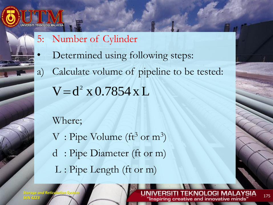
5: Number of Cylinder
• Determined using following steps:
a) Calculate volume of pipeline to be tested:
Where;
V : Pipe Volume (ft3 or m3)
d : Pipe Diameter (ft or m)
L : Pipe Length (ft or m)
Lx7854.0xdV 2
Storage and Reticulation System SKN 4223 176
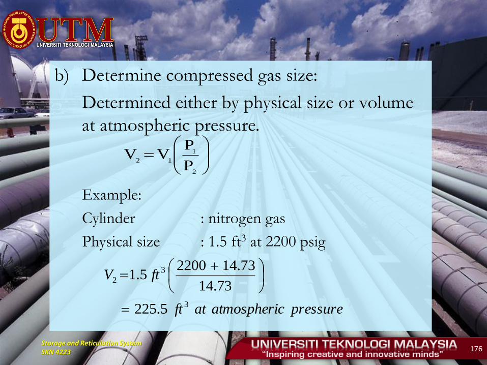
b) Determine compressed gas size:
Determined either by physical size or volume
at atmospheric pressure.
Example:
Cylinder : nitrogen gas
Physical size : 1.5 ft3 at 2200 psig
2
1
12
P
PVV
pressurecatmospheriatft
ftV
3
3
2
5.225
73.14
73.1422005.1
Storage and Reticulation System SKN 4223 177
c) Identify pressure required
Minimum test pressure can be identified by
referring to code of practice
d) Calculate the number of cylinder required
Following data required:
- Volume of pipeline
- Test pressure
- Cylinder capacity
Storage and Reticulation System SKN 4223 178
example
• Calculate the number of gas cylinder required to
perform pneumatic test for the following system:
– Pipeline volume : 175 ft3
– Test pressure : 50 psig
– Cylinder capacity : 1.5 ft3 at 2200 psig
Storage and Reticulation System SKN 4223 179
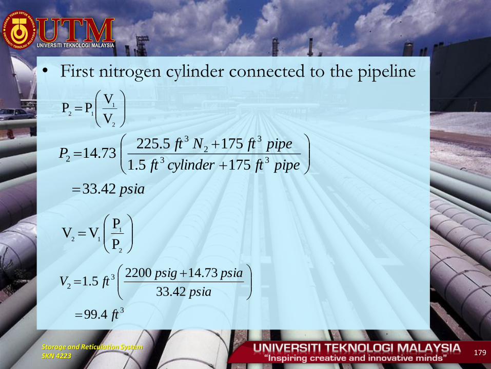
• First nitrogen cylinder connected to the pipeline
2
1
12
V
VPP
psia
pipeftcylinderft
pipeftNftP
42.33
1755.1
1755.22573.14
33
3
2
3
2
2
1
12
P
PVV
3
3
2
4.99
42.33
73.1422005.1
ft
psia
psiapsigftV
Storage and Reticulation System SKN 4223 180
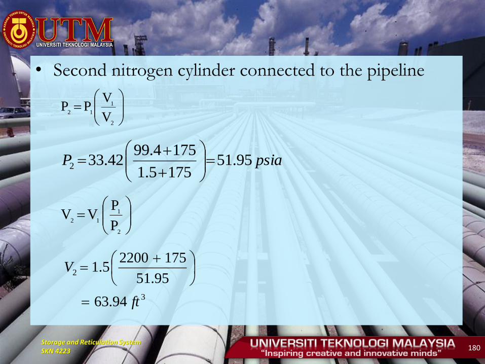
• Second nitrogen cylinder connected to the pipeline
2
1
12
V
VPP
2
1
12
P
PVV
psiaP 95.511755.1
1754.9942.332
3
2
94.63
95.51
17522005.1
ft
V
Storage and Reticulation System SKN 4223 181
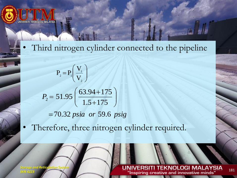
• Third nitrogen cylinder connected to the pipeline
• Therefore, three nitrogen cylinder required.
2
1
12
V
VPP
psigorpsia
P
6.5932.70
1755.1
17594.6395.512

Storage and Reticulation System SKN 4223 182
PURGING
• Purging operation should be performed to ensure the
pipeline is free from air before commissioning.
• Any failure to do the operation may lead to incident
such as fire and explosion that will cause loss in
properties and life.
• Purging can be performed through following medium:
– Inert gas (nitrogen or carbon dioxide) for pipe with
diameter of 4 inch or more
– Natural gas can be used for pipe with diameter less
than 4 inch

Storage and Reticulation System SKN 4223 183
• Velocity of mixture should be more than methane
flame speed which is 120 ft/min (2 ft/s).
• Usually the operation performed at 200 ft/min at 8
psig at the outlet point.
• This to ensure that, if any spark happens at the
outlet, the flame will not travel inwards the
pipeline.

Storage and Reticulation System SKN 4223 184
a) Pipe with diameter less than 4 inch
• Natural gas or nitrogen can used as the medium to
perform the purging operation.
• The procedure are as follows:
Medium: Natural Gas
Check the system layout and note the lower
point, uncontrollable opening and purge point.
Ensure the approval to performed the
operation have been obtained.
Purge point must be more than 0.5 inch
Storage and Reticulation System SKN 4223 185
The nearest building located more than 10 feet
and the pipeline safe from any spark supply
Purging velocity at purge pint more than 200
ft/min and 8 psig
Purge point must be monitored
The operation stopped when 100% methane gas
observed at the purge point
For a low pressure system, gas can only be burned
only when purging burner is available.
Storage and Reticulation System SKN 4223 186
Medium: Nitrogen Gas
– Calculate number of nitrogen gas cylinder required
– If manifold system used, gas must be flowed until all gas are used
– Pressure at purge point should be maintained at 8 psig and velocity of 200 ft/min
– Manifold system and purge point should be monitored throughout the operation
– The operation stopped when 100% nitrogen
Storage and Reticulation System SKN 4223 187
b) Pipe with diameter of 4 inch or more
• Inert gas (nitrogen or carbon dioxide) must be used
• The procedure are as follows:
– Calculate number of nitrogen gas cylinder required
– Manifold system must be used
– Manifold system and purge point should be
monitored throughout the operation
– Pressure at purge point should be maintained at 8
psig and velocity of 200 ft/min
– The system must be gasified after the operation
complete
Storage and Reticulation System SKN 4223 188
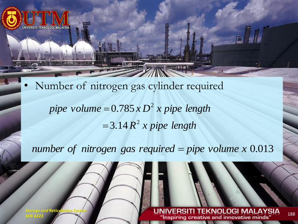
• Number of nitrogen gas cylinder required
lengthpipexR
lengthpipexDxvolumepipe
2
2
14.3
785.0
013.0xvolumepiperequiredgasnitrogenofnumber


