

1
Introduction 1-1
Chapter 1: IntroductionOur goal:
get context, overview, “feel” of networkingmore depth, detail later in courseapproach:
descriptiveuse Internet as example
Overview:what’s the Internetwhat’s a protocol?network edgenetwork coreaccess net, physical mediaInternet/ISP structureperformance: loss, delayprotocol layers, service models
Introduction 1-2
What’s the Internet: “nuts and bolts” viewmillions of connected computing devices: hosts, end-systems
PCs workstations, serversPDAs phones, toasters
running network appscommunication links
fiber, copper, radio, satellitetransmission rate = bandwidth
routers: forward packets (chunks of data)
local ISP
companynetwork
regional ISP
router workstationserver
mobile
2
Introduction 1-3
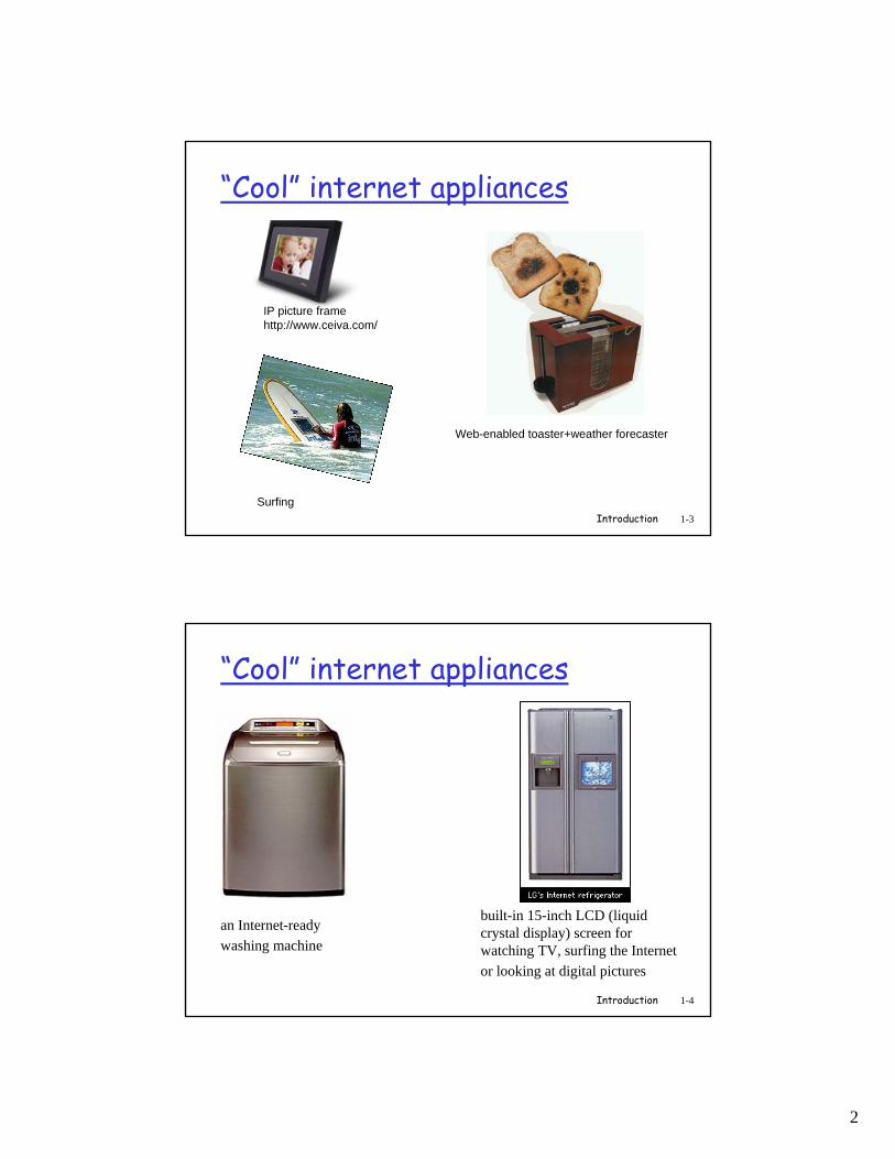
“Cool” internet appliances
IP picture framehttp://www.ceiva.com/
Web-enabled toaster+weather forecaster
Surfing
Introduction 1-4
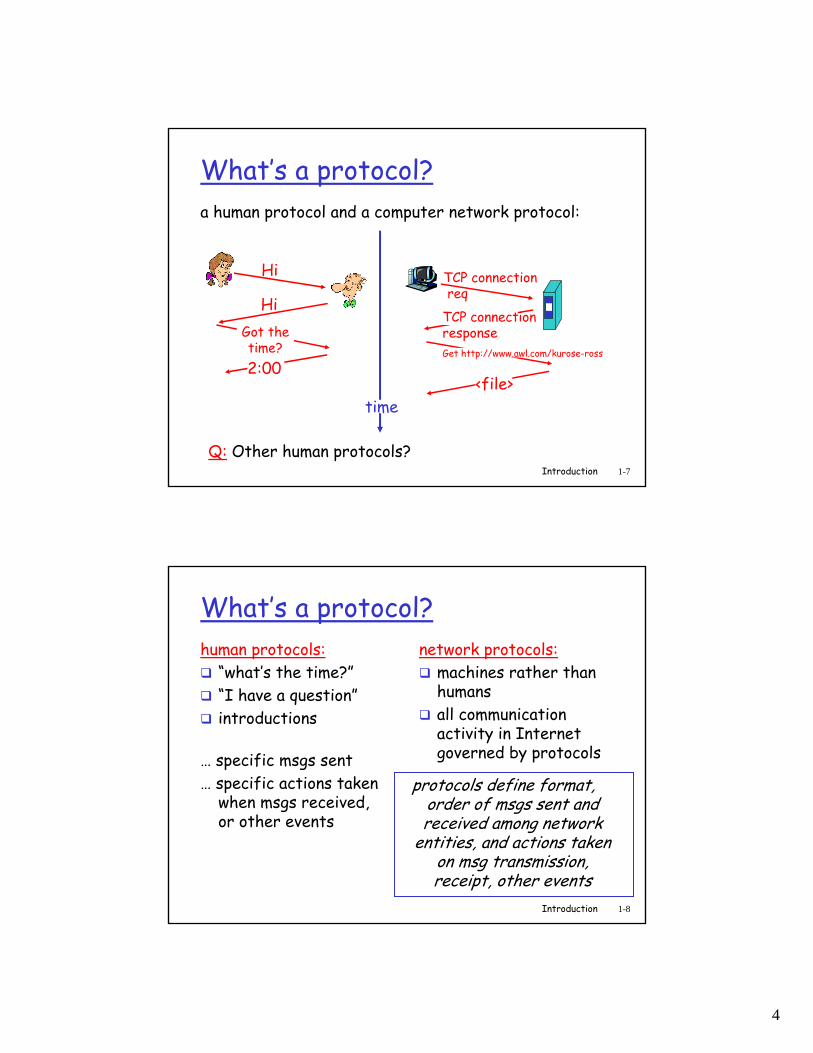
“Cool” internet appliances
an Internet-ready washing machine
built-in 15-inch LCD (liquid crystal display) screen for watching TV, surfing the Internet or looking at digital pictures

3
Introduction 1-5
What’s the Internet: “nuts and bolts” view
protocols control sending, receiving of msgs
e.g., TCP, IP, HTTP, FTP, PPPInternet: “network of networks”
loosely hierarchicalpublic Internet versus private intranet
Internet standardsRFC: Request for commentsIETF: Internet Engineering Task Force
local ISP
companynetwork
regional ISP
router workstationserver
mobile
Introduction 1-6
What’s the Internet: a service viewcommunication infrastructure enables distributed applications:
Web, email, games, e-commerce, database., voting, file (MP3) sharing
communication services provided to apps:
connectionlessconnection-oriented
4
Introduction 1-7
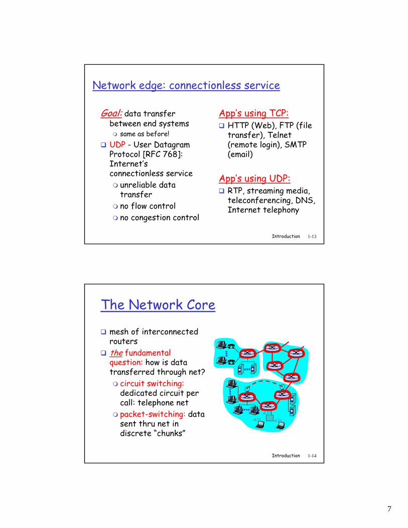
What’s a protocol?a human protocol and a computer network protocol:
Q: Other human protocols?
Hi
HiGot thetime?2:00
TCP connectionreq
TCP connectionresponseGet http://www.awl.com/kurose-ross
<file>time
Introduction 1-8
What’s a protocol?human protocols:
“what’s the time?”“I have a question”introductions
… specific msgs sent… specific actions taken
when msgs received, or other events
network protocols:machines rather than humansall communication activity in Internet governed by protocols
protocols define format, order of msgs sent and received among network
entities, and actions taken on msg transmission, receipt, other events

5
Introduction 1-9
A closer look at network structure:
network edge:applications and hostsnetwork core:
routersnetwork of networks
access networks, physical media:communication links
Introduction 1-10
The network edge:end systems (hosts):
run application programse.g. Web, emailat “edge of network”
client/server modelclient host requests, receives service from always-on servere.g. Web browser/server; email client/server

6
Introduction 1-11
The network edge:peer-peer model:
minimal (or no) use of dedicated serverse.g. Gnutella, KaZaA
Introduction 1-12
Network edge: connection-oriented service
Goal: data transfer between end systemshandshaking: setup (prepare for) data transfer ahead of time
Hello, hello back human protocolset up “state” in two communicating hosts
TCP - Transmission Control Protocol
Internet’s connection-oriented service
TCP service [RFC 793]reliable, in-order byte-stream data transfer
loss: acknowledgements and retransmissions
flow control:sender won’t overwhelm receiver
congestion control:senders “slow down sending rate” when network congested
7
Introduction 1-13
Network edge: connectionless service
Goal: data transfer between end systems
same as before!UDP - User Datagram Protocol [RFC 768]: Internet’s connectionless service
unreliable data transferno flow controlno congestion control
App’s using TCP:HTTP (Web), FTP (file transfer), Telnet (remote login), SMTP (email)
App’s using UDP:RTP, streaming media, teleconferencing, DNS, Internet telephony
Introduction 1-14
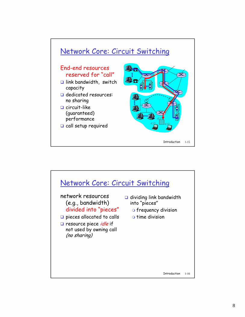
The Network Core
mesh of interconnected routersthe fundamental question: how is data transferred through net?
circuit switching:dedicated circuit per call: telephone netpacket-switching: data sent thru net in discrete “chunks”
8
Introduction 1-15
Network Core: Circuit Switching
End-end resources reserved for “call”link bandwidth, switch capacitydedicated resources: no sharingcircuit-like (guaranteed) performancecall setup required
Introduction 1-16
Network Core: Circuit Switchingnetwork resources
(e.g., bandwidth) divided into “pieces”pieces allocated to callsresource piece idle if not used by owning call (no sharing)
dividing link bandwidth into “pieces”
frequency divisiontime division

9
Introduction 1-17
Circuit Switching: FDMA and TDMA
FDMA
frequency
timeTDMA
frequency
time
4 usersExample:
Introduction 1-18
Network Core: Packet Switchingeach end-end data stream
divided into packetsuser A, B packets sharenetwork resourceseach packet uses full link bandwidth resources used as needed
resource contention:aggregate resource demand can exceed available capacitycongestion: packets queue, wait for link usestore and forward: packets move one hop at a time
transmit over linkwait turn at next link
Bandwidth division into “pieces”Dedicated allocationResource reservation
10
Introduction 1-19
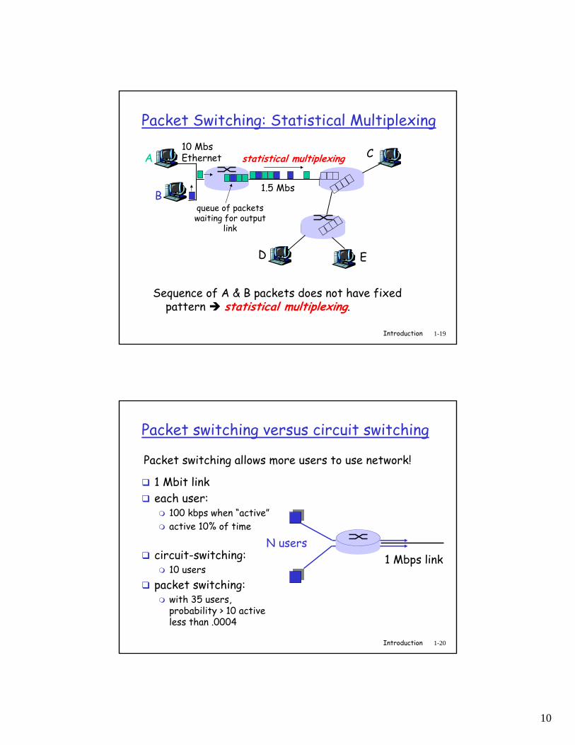
Packet Switching: Statistical Multiplexing
Sequence of A & B packets does not have fixed pattern statistical multiplexing.
A
B
C10 MbsEthernet
1.5 Mbs
D E
statistical multiplexing
queue of packetswaiting for output
link
Introduction 1-20
Packet switching versus circuit switching
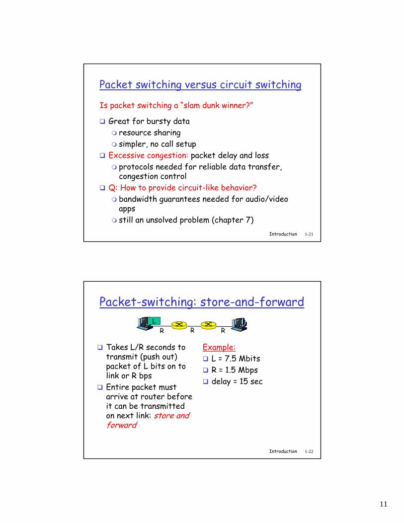
1 Mbit linkeach user:
100 kbps when “active”active 10% of time
circuit-switching: 10 users
packet switching: with 35 users, probability > 10 active less than .0004
Packet switching allows more users to use network!
N users1 Mbps link
11
Introduction 1-21
Packet switching versus circuit switching
Great for bursty dataresource sharingsimpler, no call setup
Excessive congestion: packet delay and lossprotocols needed for reliable data transfer, congestion control
Q: How to provide circuit-like behavior?bandwidth guarantees needed for audio/video appsstill an unsolved problem (chapter 7)
Is packet switching a “slam dunk winner?”
Introduction 1-22
Packet-switching: store-and-forward
Takes L/R seconds to transmit (push out) packet of L bits on to link or R bpsEntire packet must arrive at router before it can be transmitted on next link: store and forward
Example:L = 7.5 MbitsR = 1.5 Mbpsdelay = 15 sec
R R RL

12
Introduction 1-23
Packet Switching: Message Fragmentation
Now break up message L into 1500 bits packetsTotal of 5000 packets1 msec to transmit packet on one linkpipelining: each link works in parallelDelay reduced from 15 sec to 5.002 sec
Introduction 1-24
Packet-switched networks: forwarding
Goal: move packets through routers from source to destination
we’ll study several path selection (i.e. routing)algorithms (chapter 4)
datagram network:destination address in packet determines next hoproutes may change during sessionanalogy: post office, driving, asking directions
virtual circuit network:each packet carries tag (virtual circuit ID), tag determines next hopfixed path determined at call setup time, remains fixed thru callrouters maintain per-call state
13
Introduction 1-25
Access Networks
Q: How to connect end systems to edge router?residential access netsinstitutional access networks (school, company)mobile access networks
Keep in mind: bandwidth (bits per second) of access network?shared or dedicated?
Introduction 1-26
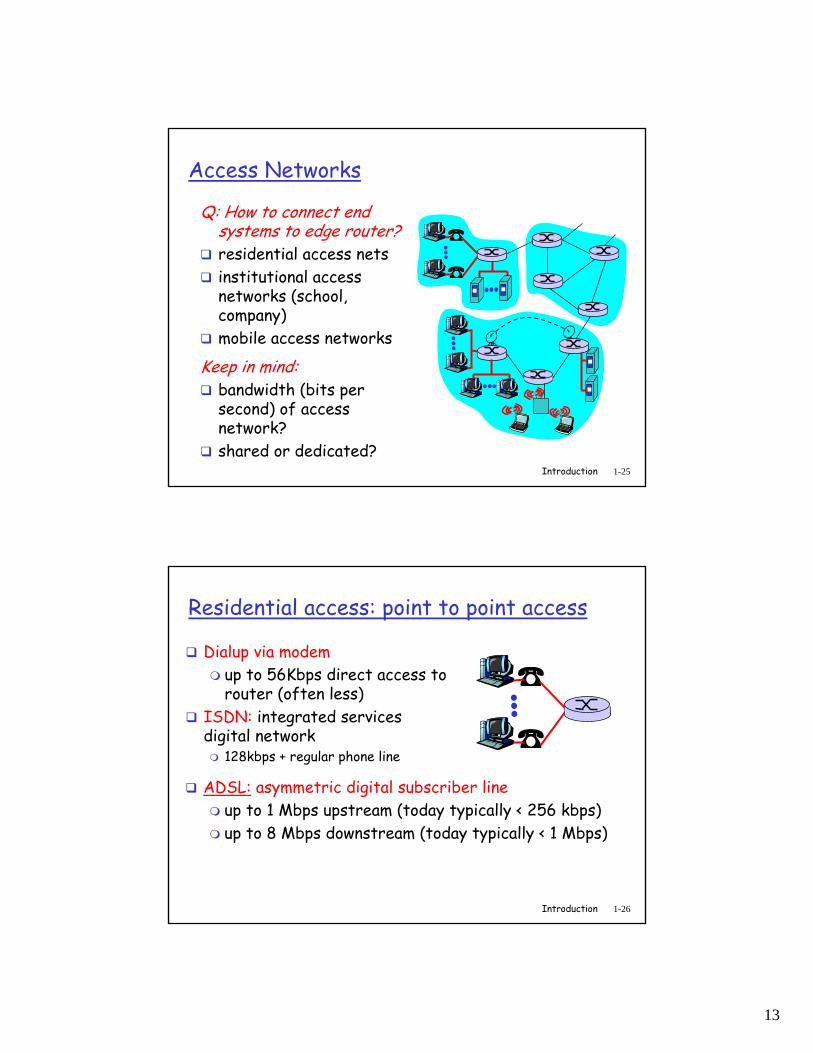
Residential access: point to point access
Dialup via modemup to 56Kbps direct access to router (often less)
ISDN: integrated services digital network
128kbps + regular phone line
ADSL: asymmetric digital subscriber lineup to 1 Mbps upstream (today typically < 256 kbps)up to 8 Mbps downstream (today typically < 1 Mbps)

14
Introduction 1-27
Residential access: cable modems
HFC: hybrid fiber coaxasymmetric: up to 10Mbps downstream, 1 Mbps upstream
network of cable and fiber attaches homes to ISP router
shared access to router among homeissues: congestion, dimensioning
deployment: available via cable companies, e.g., MediaOne, ATT, Comcast
Introduction 1-28
Residential access: cable modems
Diagram: http://www.cabledatacomnews.com/cmic/diagram.html

15
Introduction 1-29
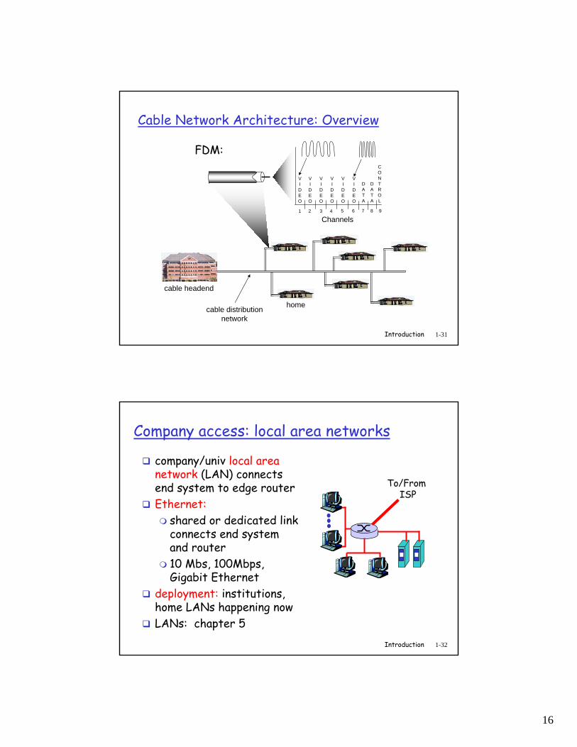
Cable Network Architecture: Overview
home
cable headend
cable distributionnetwork (simplified)
Typically 500 to 5,000 homes
Introduction 1-30
Cable Network Architecture: Overview
home
cable headend
cable distributionnetwork
server(s)
16
Introduction 1-31
Cable Network Architecture: Overview
home
cable headend
cable distributionnetwork
Channels
VIDEO
VIDEO
VIDEO
VIDEO
VIDEO
VIDEO
DATA
DATA
CONTROL
1 2 3 4 5 6 7 8 9
FDM:
Introduction 1-32
Company access: local area networks
company/univ local area network (LAN) connects end system to edge routerEthernet:
shared or dedicated link connects end system and router10 Mbs, 100Mbps, Gigabit Ethernet
deployment: institutions, home LANs happening nowLANs: chapter 5
To/From ISP

17
Introduction 1-33
Wireless access networksshared wireless access network connects end system to router
via base station aka “access point”
wireless LANs:802.11b (WiFi): 11 Mbps
wider-area wireless accessprovided by telcom operator3G ~ 384 kbps
• Will it happen??WAP/GPRS in Europe
basestation
mobilehosts
router
Introduction 1-34
Home networksTypical home network components:
ADSL or cable modemrouter/firewall/NATEthernetwireless accesspoint
wirelessaccess point
wirelesslaptops
router/firewall
cablemodem
to/fromcable
headend
Ethernet(switched)
18
Introduction 1-35
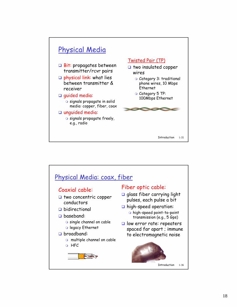
Physical Media
Bit: propagates betweentransmitter/rcvr pairsphysical link: what lies between transmitter & receiverguided media:
signals propagate in solid media: copper, fiber, coax
unguided media:signals propagate freely, e.g., radio
Twisted Pair (TP)two insulated copper wires
Category 3: traditional phone wires, 10 Mbps EthernetCategory 5 TP: 100Mbps Ethernet
Introduction 1-36
Physical Media: coax, fiber
Coaxial cable:two concentric copper conductorsbidirectionalbaseband:
single channel on cablelegacy Ethernet
broadband:multiple channel on cableHFC
Fiber optic cable:glass fiber carrying light pulses, each pulse a bithigh-speed operation:
high-speed point-to-point transmission (e.g., 5 Gps)
low error rate: repeaters spaced far apart ; immune to electromagnetic noise
19
Introduction 1-37
Physical media: radio
signal carried in electromagnetic spectrumno physical “wire”bidirectionalpropagation environment effects:
reflection obstruction by objectsinterference
Radio link types:terrestrial microwave
e.g. up to 45 Mbps channelsLAN (e.g., WaveLAN)
2Mbps, 11Mbpswide-area (e.g., cellular)
e.g. 3G: hundreds of kbpssatellite
up to 50Mbps channel (or multiple smaller channels)270 msec end-end delaygeosynchronous versus LEOS


