
Chapter 8. Separation and Classification of Nanoparticles
8.1 Introduction
- Separation = recovery = collection
- Classification
Separation Mechanisms
- Sedimentation*: Settling chamber, centrifuge
- Inertial deposition: Cyclone*, scrubber, inertial impactor
- Brownian diffusion: Diffusion batteries
- Migration of charged particle in an electric field :
Electrostatic precipitator, dynamic mobility analyzer
- Thermophoresis: Thermal precipitator (thermopositor)
- Filters: particle collection by the combined mechanism.
* Generally not suitable for nanoparticle collection but used for precollector
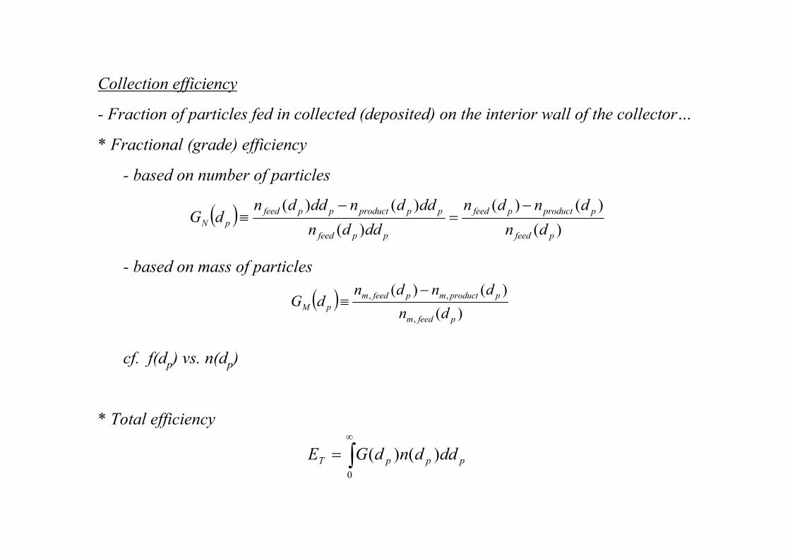
Collection efficiency
- Fraction of particles fed in collected (deposited) on the interior wall of the collector…
* Fractional (grade) efficiency
- based on number of particles
- based on mass of particles
cf. f(dp) vs. n(dp)
* Total efficiency
( ))(
)()(
)(
)()(
pfeed
pproductpfeed
ppfeed
ppproductppfeed
pNdn
dndn
dddn
dddndddndG
−=
−≡
( ))(
)()(
,
,,
pfeedm
pproductmpfeedm
pMdn
dndndG
−≡
∫∞
=0
)()( pppT dddndGE
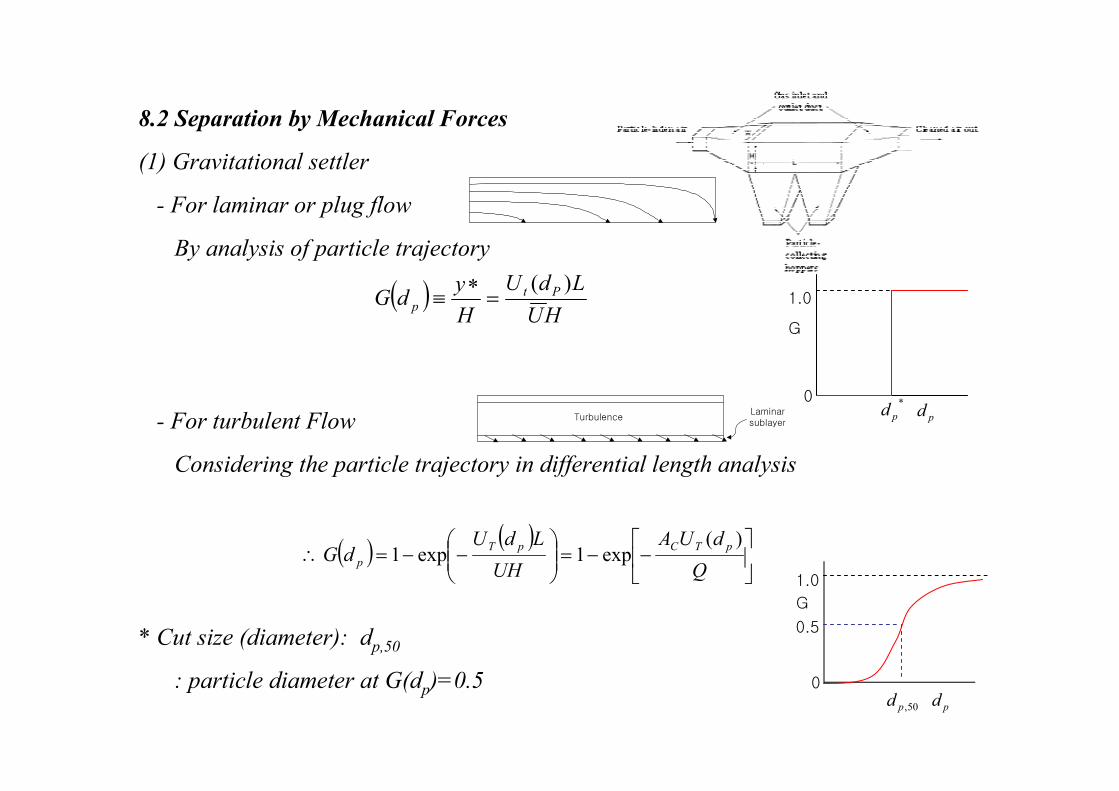
8.2 Separation by Mechanical Forces
(1) Gravitational settler
- For laminar or plug flow
By analysis of particle trajectory
- For turbulent Flow
Considering the particle trajectory in differential length analysis
* Cut size (diameter): dp,50
: particle diameter at G(dp)=0.5
Turbulence Laminar sublayer
G
pd0
1.0
0.5
50,pd
G
pd0
1.0
*
pd
( )HU
LdU
H
ydG Pt
p
)(=
∗≡
( ) ( )
−−=
−−=∴
Q
dUA
UH
LdUdG
pTCpT
p
)(exp1exp1
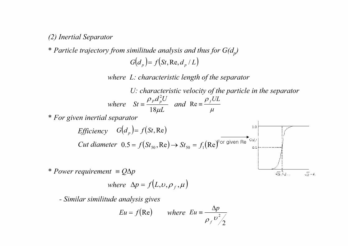
(2) Inertial Separator
* Particle trajectory from similitude analysis and thus for G(dp)
where L: characteristic length of the separator
U: characteristic velocity of the particle in the separator
where and
* For given inertial separator
Efficiency
Cut diameter
* Power requirement
where
- Similar similitude analysis gives
where
( ) ( )LdStfdG pp /Re,,=
L
UdSt
pP
µ
ρ
18
2
≡µ
ρ ULf≡Re
pQ∆≡
( )µρυ ,,, fLfp =∆
( )RefEu =
2
2υρ f
pEu
∆≡
( ) ( )Re,StfdG p =
( ) ( )ReRe,5.0 15050 fStStf =→= For given Re
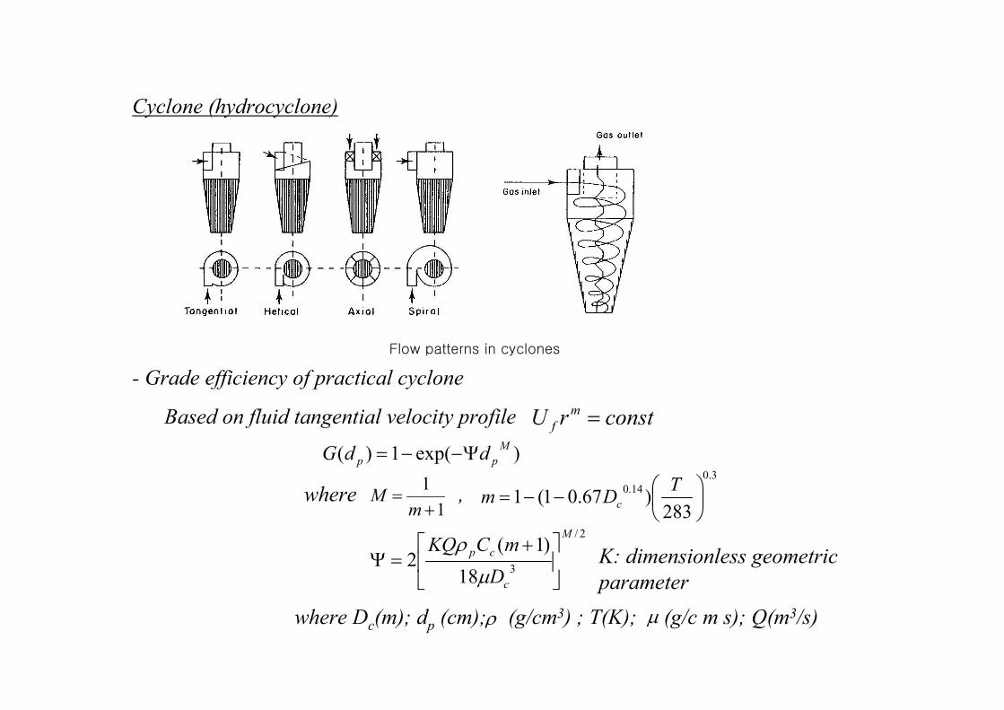
Cyclone (hydrocyclone)
- Grade efficiency of practical cyclone
Based on fluid tangential velocity profile
where ,
Flow patterns in cyclones
)exp(1)(M
pp ddG Ψ−−=
1
1
+=m
M
3.0
14.0
283)67.01(1
−−=T
Dm c
constrU m
f =
2/
318
)1(2
M
c
cp
D
mCKQ
+=Ψ
µ
ρ
where Dc(m); dp (cm); (g/cm3) ; T(K); (g/c m s); Q(m3/s)ρ µ
K: dimensionless geometric
parameter
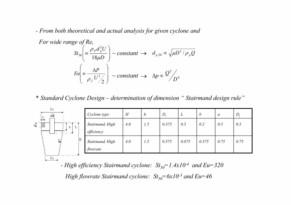
- From both theoretical and actual analysis for given cyclone and
For wide range of Re,
~ constant
~ constant
* Standard Cyclone Design – determination of dimension “ Stairmand design rule”
- High efficiency Stairmand cyclone: St50=1.4x10⁻⁴ and Eu=320
High flowrate Stairmand cyclone: St50=6x10⁻³ and Eu=46
≡
D
UdSt
pP
µ
ρ
18
2
50 → QDd pp ρµ /350, ∝
∆
≡
2
2U
PEu
fρ4
2
DQ
p ∝∆→
0.750.750.3750.8750.5751.54.0Stairmand, High
flowrate
0.50.50.20.50.3751.54.0Stairmand, High
efficiency
DjabLDshHCyclone type
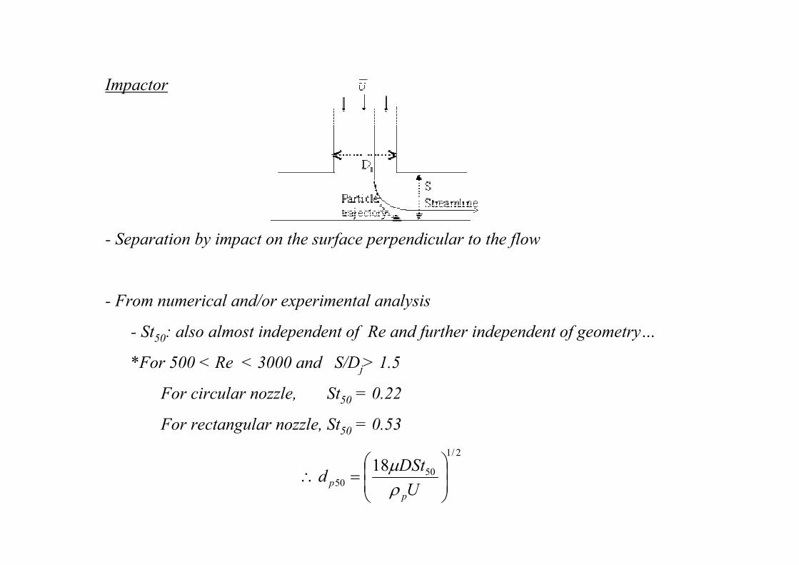
Impactor
- Separation by impact on the surface perpendicular to the flow
- From numerical and/or experimental analysis
- St50: also almost independent of Re and further independent of geometry…
*For 500 < Re < 3000 and S/Dj> 1.5
For circular nozzle, St50 = 0.22
For rectangular nozzle, St50 = 0.53
2/1
5050
18
=∴
U
DStd
p
p ρµ
- To collect nanoparticles, D↓ ↓, U↓ ↓ and Cc↑ ↑
Vacuum operation with supersonic velocity is required…
“hypersonic impactor”
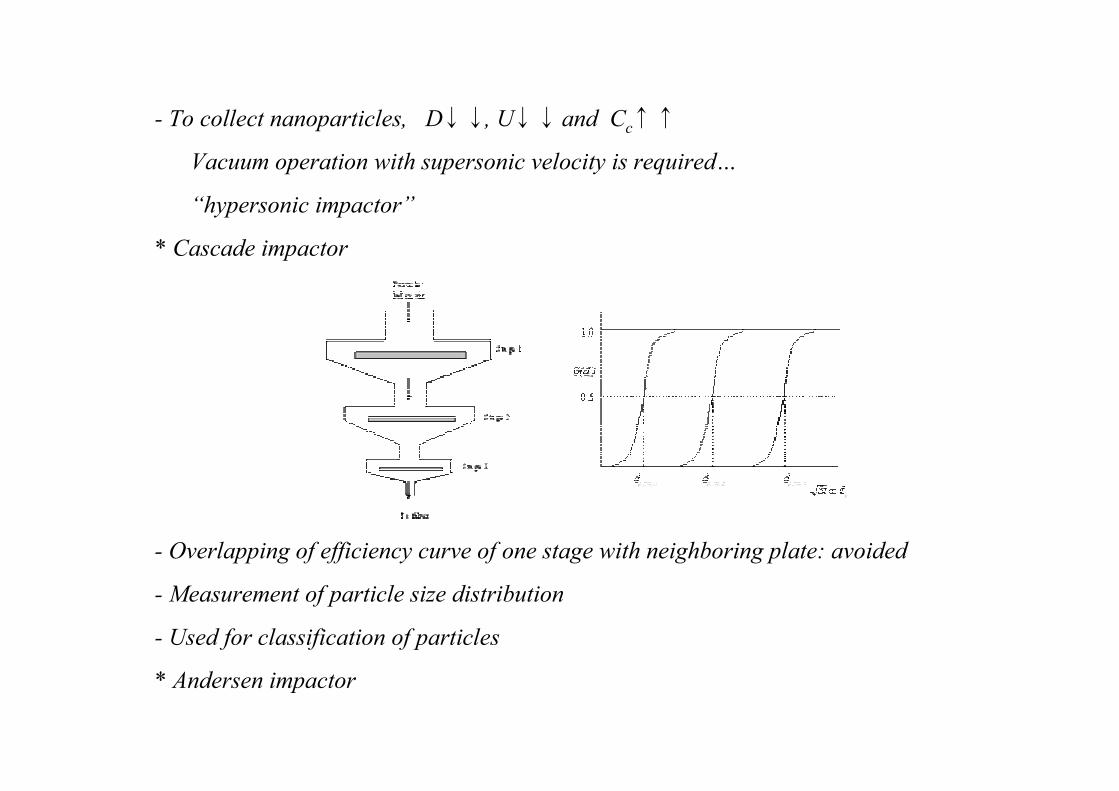
* Cascade impactor
- Overlapping of efficiency curve of one stage with neighboring plate: avoided
- Measurement of particle size distribution
- Used for classification of particles
* Andersen impactor
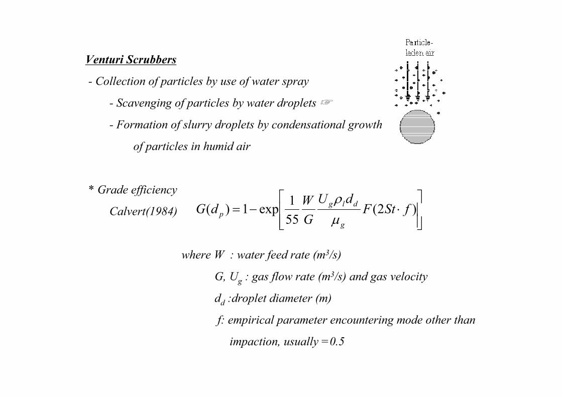
Venturi Scrubbers
- Collection of particles by use of water spray
- Scavenging of particles by water droplets
- Formation of slurry droplets by condensational growth
of particles in humid air
* Grade efficiency
Calvert(1984)
where W : water feed rate (m3/s)
G, Ug : gas flow rate (m3/s) and gas velocity
dd :droplet diameter (m)
f: empirical parameter encountering mode other than
impaction, usually =0.5
⋅−= )2(
55
1exp1)( fStF
dU
G
WdG
g
dlg
p µ
ρ
* Characteristics of venturi scrubber
- High efficient for particles smaller than 2 um
- The only choice for sticky, flammable or highly corrosive particles
- High gas velocity(~120 m/s)→ smaller-size equipment made of less corrosion-
resistant materials
- Liquid-to-gas volumetric flow rate ratio = 0.001~0.003
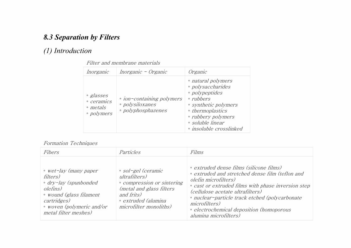
8.3 Separation by Filters
(1) Introduction
natural polymers polysaccharides polypeptides rubbers synthetic polymers thermoplastics rubbery polymers soluble linear insoluble crosslinked
ion-containing polymers polysiloxanes polyphosphazenes
glasses ceramics metals polymers
OrganicInorganic - OrganicInorganic
Filter and membrane materials
extruded dense films (silicone films) extruded and stretched dense film (teflon and olefin microfilters) cast or extruded films with phase inversion step (cellulose acetate ultrafilters) nuclear-particle track etched (polycarbonate microfilters) electrochemical deposition (homoporous alumina microfilters)
sol-gel (ceramic ultrafilters) compression or sintering (metal and glass filters and frits) extruded (alumina microfilter monoliths)
wet-lay (many paper filters) dry-lay (spunbonded olefins) wound (glass filament cartridges) woven (polymeric and/or metal filter meshes)
FilmsParticlesFibers
Formation Techniques
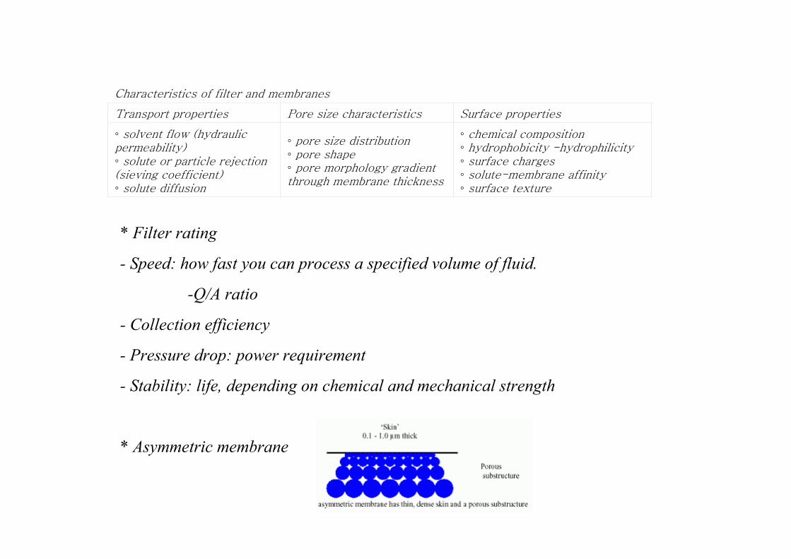
chemical composition hydrophobicity -hydrophilicity surface charges solute-membrane affinity surface texture
pore size distribution pore shape pore morphology gradient through membrane thickness
solvent flow (hydraulic permeability) solute or particle rejection (sieving coefficient) solute diffusion
Surface propertiesPore size characteristicsTransport properties
Characteristics of filter and membranes
* Filter rating
- Speed: how fast you can process a specified volume of fluid.
-Q/A ratio
- Collection efficiency
- Pressure drop: power requirement
- Stability: life, depending on chemical and mechanical strength
* Asymmetric membrane
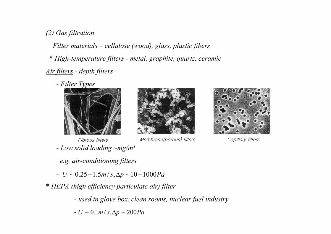
(2) Gas filtration
Filter materials – cellulose (wood), glass, plastic fibers
* High-temperature filters - metal. graphite, quartz, ceramic
Air filters - depth filters
- Filter Types
- Low solid loading ~mg/m3
e.g. air-conditioning filters
-
* HEPA (high efficiency particulate air) filter
- used in glove box, clean rooms, nuclear fuel industry
-
Fibrous filters Membrane(porous) filters Capillary filters
PapsmU 100010~,/5.125.0~ −∆−
PapsmU 200~,/1.0~ ∆
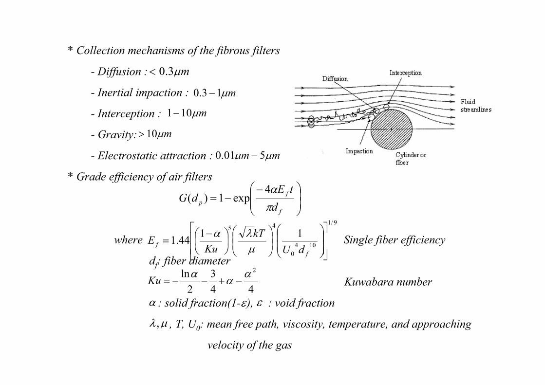
* Collection mechanisms of the fibrous filters
- Diffusion :
- Inertial impaction :
- Interception :
- Gravity:
- Electrostatic attraction :
* Grade efficiency of air filters
where Single fiber efficiency
df: fiber diameter
Kuwabara number
: solid fraction(1- ), : void fraction
, T, U0: mean free path, viscosity, temperature, and approaching
velocity of the gas
mµ3.0<
mµ13.0 −
mµ101−
mµ10>
mm µµ 501.0 −
−−=
f
f
pd
tEdG
π
α4exp1)(
9/1
104
0
4511
44.1
−=
f
fdU
kT
KuE
µλα
44
3
2
ln 2αα
α−+−−=Ku
α ε
µλ,
ε
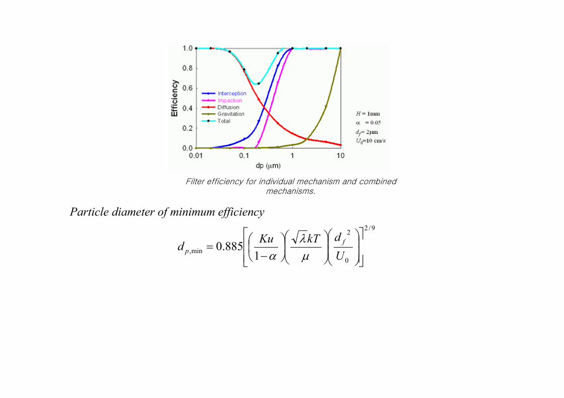
Particle diameter of minimum efficiency
Filter efficiency for individual mechanism and combinedmechanisms.
9/2
0
2
min,1
885.0
−
=U
dkTKud
f
p µλ
α
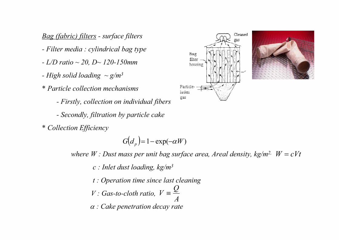
Bag (fabric) filters - surface filters
- Filter media : cylindrical bag type
- L/D ratio ~ 20, D~ 120-150mm
- High solid loading ~ g/m3
* Particle collection mechanisms
- Firstly, collection on individual fibers
- Secondly, filtration by particle cake
* Collection Efficiency
where W : Dust mass per unit bag surface area, Areal density, kg/m2,
c : Inlet dust loading, kg/m3
t : Operation time since last cleaning
V : Gas-to-cloth ratio,
: Cake penetration decay rate
( ) )exp(1 WdG p α−−=
cVtW =
A
QV ≡
α
* Permeation rate and pressure drop
where Rm: resistance of filter media, reciprocal of permeance
Rc: resistance of filter cake,
K: function of the properties of dust
- Constant-pressure operation: permeation rate decrease
* Regeneration (cleaning) of filters
- shaker (vibrator), reverse flow, pulse jet
- use of cleaning ring
)(
)(
tRR
tpV
Cm +∆
=
( ) KcVttRc =
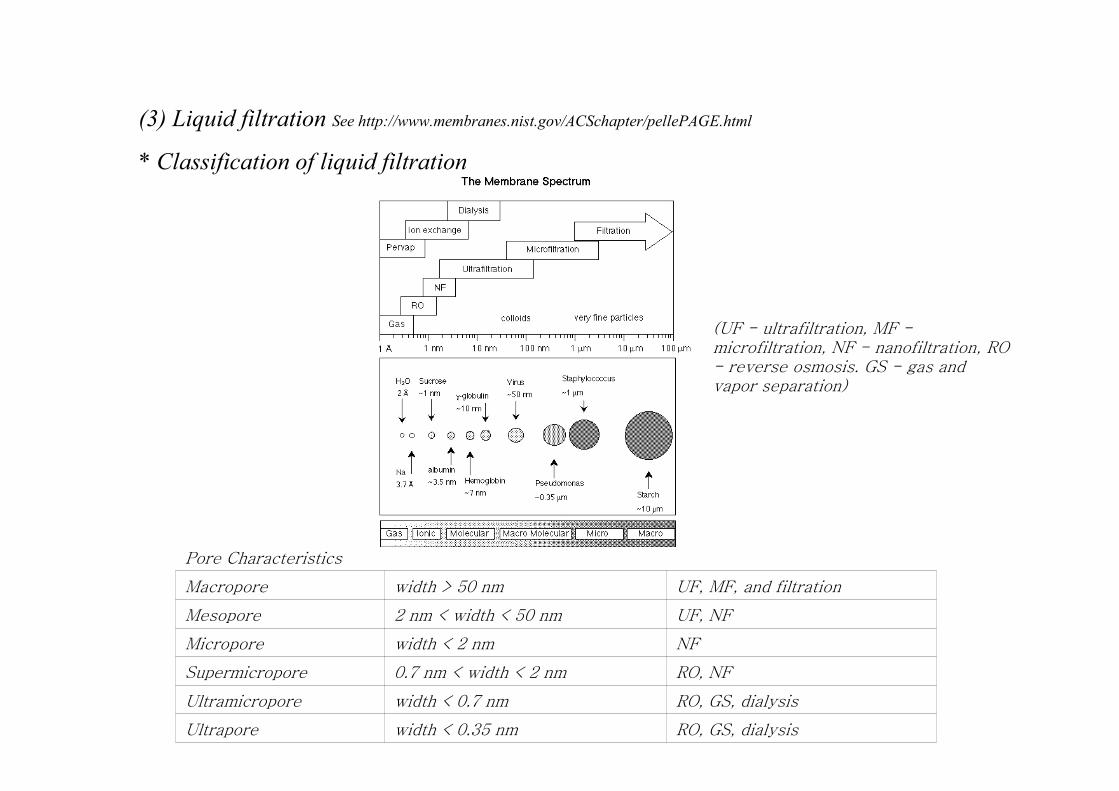
(3) Liquid filtration See http://www.membranes.nist.gov/ACSchapter/pellePAGE.html
* Classification of liquid filtration
RO, GS, dialysiswidth < 0.35 nmUltrapore
RO, GS, dialysiswidth < 0.7 nmUltramicropore
RO, NF0.7 nm < width < 2 nmSupermicropore
NFwidth < 2 nmMicropore
UF, NF2 nm < width < 50 nmMesopore
UF, MF, and filtrationwidth > 50 nmMacropore
Pore Characteristics
(UF - ultrafiltration, MF -microfiltration, NF - nanofiltration, RO - reverse osmosis. GS - gas and vapor separation)
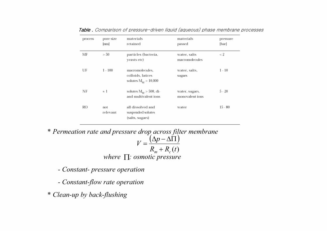
Table . Table . Table . Table . Comparison of pressure-driven liquid (aqueous) phase membrane processes
* Permeation rate and pressure drop across filter membrane
where : osmotic pressure
- Constant- pressure operation
- Constant-flow rate operation
* Clean-up by back-flushing
( ))(tRR
pV
cm +∆Π−∆
=
Π
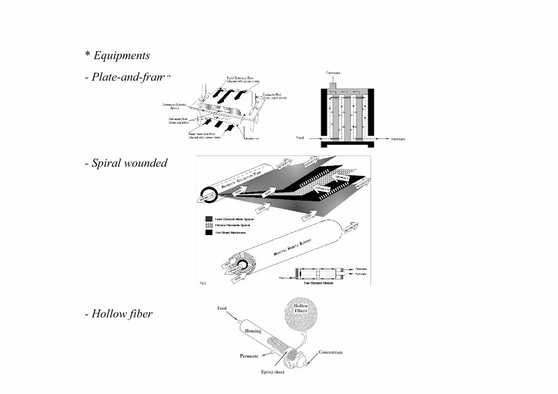
* Equipments
- Plate-and-frame
- Spiral wounded
- Hollow fiber
8.4 Separation by Nonequilibrium Gas
(1) Thermal precipitators
- Collection efficiency for particles having
- Used in lab-scale particle collection for electron microscopes
- Volumetric flow rate ~ 4-5cm3/min
- ΔT=50-200K with 1000-10000K/cm
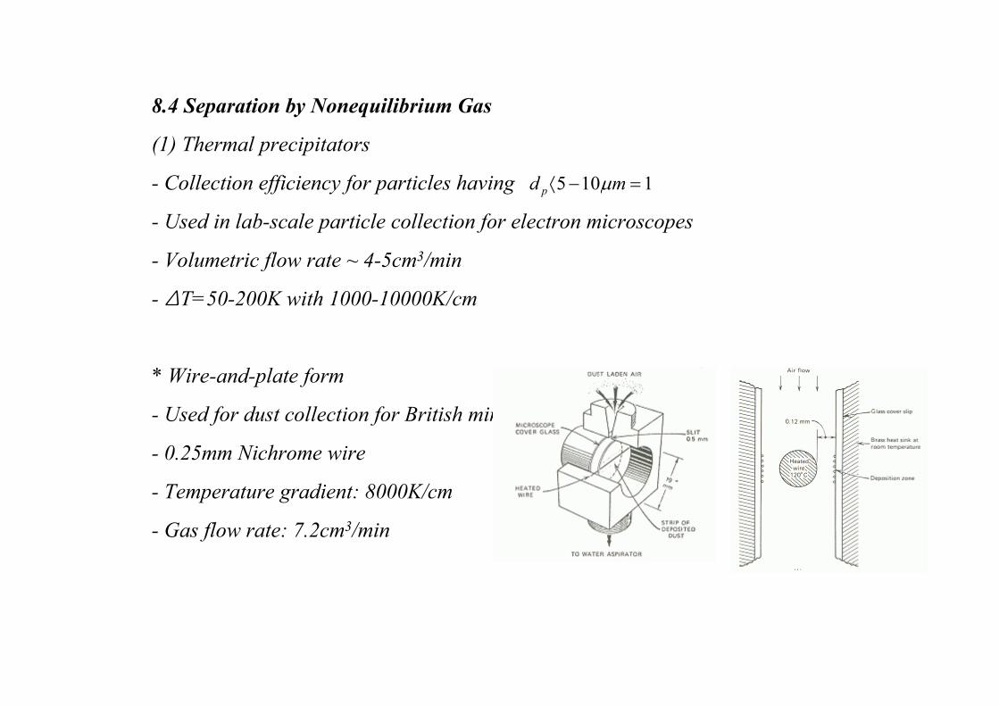
* Wire-and-plate form
- Used for dust collection for British mines
- 0.25mm Nichrome wire
- Temperature gradient: 8000K/cm
- Gas flow rate: 7.2cm3/min
1105 =−⟨ md p µ
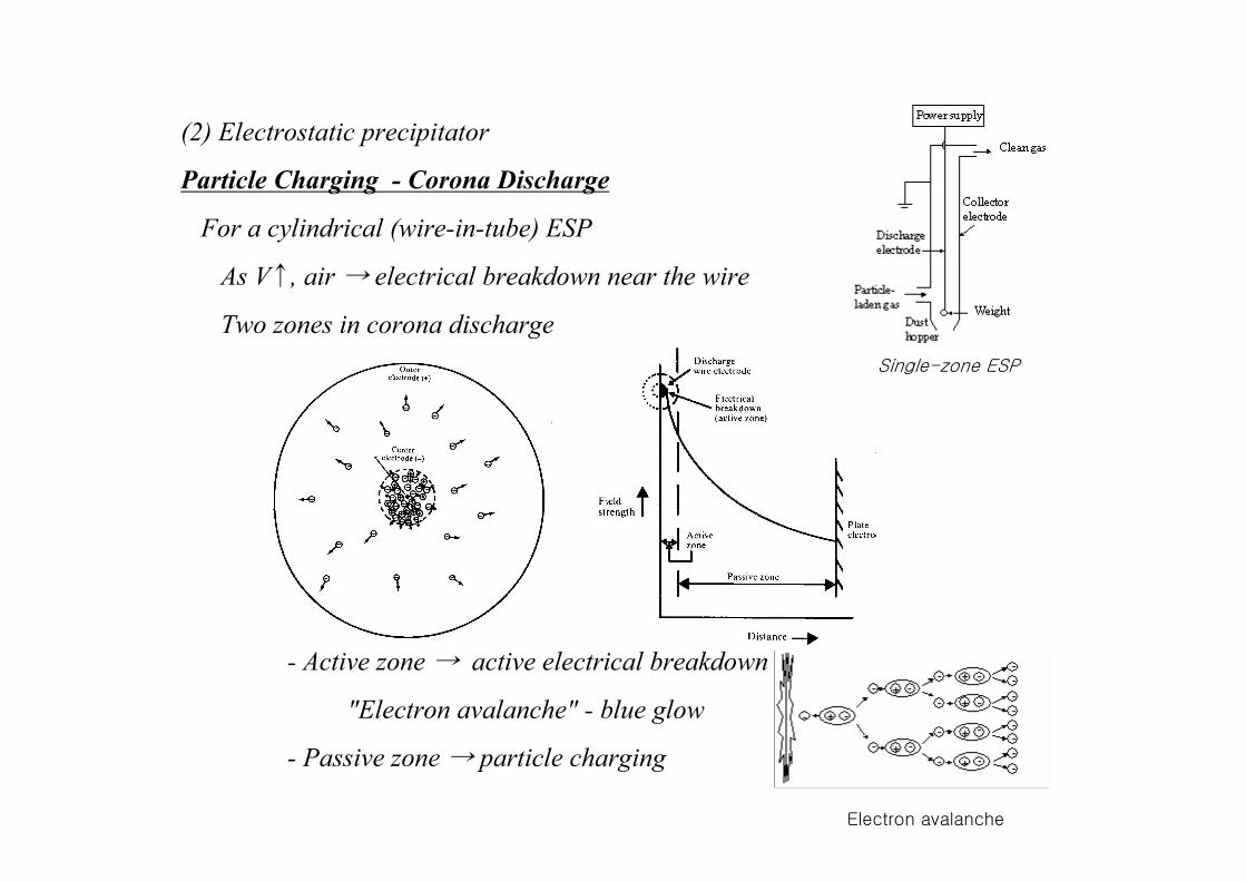
(2) Electrostatic precipitator
Particle Charging - Corona Discharge
For a cylindrical (wire-in-tube) ESP
As V↑, air → electrical breakdown near the wire
Two zones in corona discharge
- Active zone → active electrical breakdown
"Electron avalanche" - blue glow
- Passive zone → particle charging
Single-zone ESP
Electron avalanche
* Positive corona vs. negative corona
*Diffusion charging vs. field charging
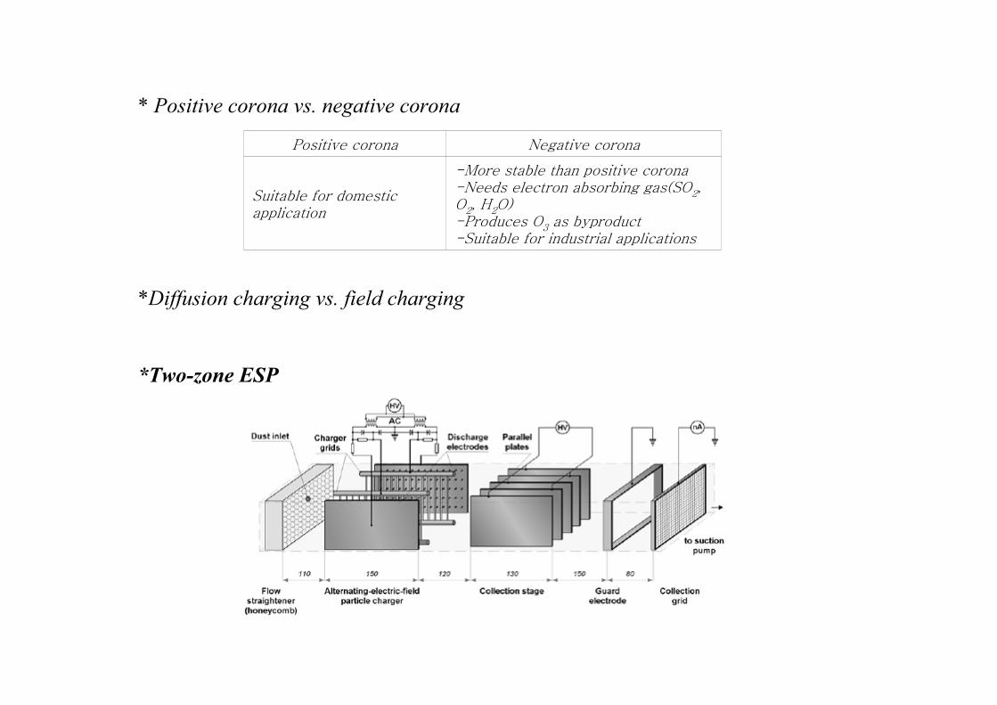
*Two-zone ESP
-More stable than positive corona-Needs electron absorbing gas(SO2, O2, H2O)-Produces O3 as byproduct-Suitable for industrial applications
Suitable for domestic application
Negative coronaPositive corona
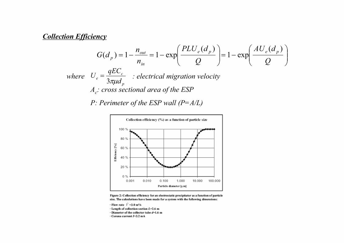
Collection Efficiency
where : electrical migration velocity
Ac: cross sectional area of the ESP
P: Perimeter of the ESP wall (P=A/L)
−=
−=−=
Q
dAU
Q
dPLU
n
ndG
pepe
in
outp
)(exp1
)(exp11)(
p
ce
d
qECU
πµ3=
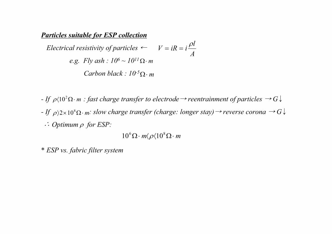
Particles suitable for ESP collection
Electrical resistivity of particles ←
e.g. Fly ash : 106 ~ 1011
Carbon black : 10-5
- If : fast charge transfer to electrode→ reentrainment of particles → G↓
- If : slow charge transfer (charge: longer stay)→ reverse corona → G↓
∴ Optimum for ESP:
* ESP vs. fabric filter system
A
liiRVρ
==
m⋅Ω
m⋅Ω
m⋅Ω⟨ 210ρ
m⋅Ω×⟩ 8102ρ
mm ⋅Ω⟨⟨⋅Ω 86 1010 ρ
ρ


