

CHEM-AD� SERIES ADIAPHRAGM
METERING PUMPBOOK NO. IM 440.600AA UA ISSUE A

IM 440.600AA UA (A/12-02)
CHEM-AD� SERIES A
EQUIPMENT SERIAL NO. _________________
DATE OF START-UP _____________________
START-UP BY ___________________________
Prompt service available from nationwide authorized service contractors.
ORDERING INFORMATION
In order for us to fill your order immediately and correctly, please order material by description and part number, as shown inthis book. Also, please specify the serial number of the equipment on which the parts will be installed.
WARRANTY
Seller warrants for a period of one year after shipment that the equipment or material of its manufacture is free from defectsin workmanship and materials. Corrosion or other decomposition by chemical action is specifically excluded as a defectcovered hereunder, except this exclusion shall not apply to chlorination equipment. Seller does not warrant (a) damagecaused by use of the items for purposes other than those for which they were designed, (b) damage caused by unauthorizedattachments or modifications, (c) products subject to any abuse, misuse, negligence or accident, (d) products where parts notmade, supplied, or approved by Seller are used and in the sole judgement of the Seller such use affects the products�performance, stability or reliability, and (e) products that have been altered or repaired in a manner in which, in the solejudgement of Seller, affects the products� performance, stability or reliability. SELLER MAKES NO OTHER WARRANTY OFANY KIND, AND THE FOREGOING WARRANTY IS IN LIEU OF ALL OTHER WARRANTIES, EXPRESS OR IMPLIED,INCLUDING ANY WARRANTY OF MERCHANTABILITY OR OF FITNESS OF THE MATERIAL OR EQUIPMENT FORANY PARTICULAR PURPOSE EVEN IF THAT PURPOSE IS KNOWN TO SELLER. If Buyer discovers a defect in materialor workmanship, it must promptly notify Seller in writing; Seller reserves the right to require the return of such defective partsto Seller, transportation charges prepaid, to verify such defect before this warranty is applicable. In no event shall suchnotification be received by Seller later than 13 months after the date of shipment. No action for breach of warranty shall bebrought more than 15 months after the date of shipment of the equipment or material.
LIMITATION OF BUYER�S REMEDIES. The EXCLUSIVE REMEDY for any breach of warranty is the replacement f.o.b.shipping point of the defective part or parts of the material or equipment. Any equipment or material repaired or replacedunder warranty shall carry the balance of the original warranty period, or a minimum of three months. Seller shall not be liablefor any liquidated, special, incidental or consequential damages, including without limitation, loss of profits, loss of savings orrevenue, loss of use of the material or equipment or any associated material or equipment, the cost of substitute material orequipment, claims of third parties, damage to property, or goodwill, whether based upon breach of warranty, breach ofcontract, negligence, strict tort, or any other legal theory; provided, however, that such limitation shall not apply to claims forpersonal injury.
Statements and instructions set forth herein are based upon the best information and practices known to U.S. Filter/Wallace& Tiernan, Inc., but it should not be assumed that every acceptable safety procedure is contained herein. Of necessity thiscompany cannot guarantee that actions in accordance with such statements and instructions will result in the completeelimination of hazards and it assumes no liability for accidents that may occur.
1.010-42
WALLACE & TIERNAN PRODUCTS1901 West Garden Road, Vineland, NJ 08360
CHEM-AD� SERIES A
IM 440.600AA UA (A/12-02) Introd.
INTRODUCTION
This technical manual contains all the necessary instructions for the in-stallation, start-up, maintenance, and repair of the USFilter�s Wallace &Tiernan Products (USF/W&T) Chem-Ad� Series A Diaphragm MeteringPumps.
WARNING: HAZARDOUS GAS MAY BE PRESENT IN THISEQUIPMENT DURING NORMAL OPERATION. TO AVOIDPOSSIBLE SEVERE PERSONAL INJURY OR DAMAGE TO THEEQUIPMENT, READ THIS INSTRUCTION BOOK BEFORE CON-NECTING THIS EQUIPMENT TO A SUPPLY OF GAS. OPERA-TION AND MAINTENANCE OF THIS EQUIPMENT MUST BERESTRICTED TO TRAINED, QUALIFIED PERSONNEL WHOARE COMPLETELY FAMILIAR WITH THESE INSTRUCTIONS.CONSULT FACTORY FOR APPLICATIONS AGAINST A NEGA-TIVE HEAD (PARTIAL VACUUM) OR A POSITIVEBACKPRESSURE OF LESS THAN 1.0 PSI (28 INCHES OF WA-TER) IN THE SOLUTION DISCHARGE LINE.
NOTE: When ordering material, always specify model and serialnumber of apparatus.
TABLE OF CONTENTS
Very Important Safety Precautions .......................... SP-1Notes on Protective Equipment and Clothing .......... 1.010-6Regional Offices ....................................................... 1.010-1Technical Data .......................................................... Section 1Installation ................................................................ Section 2Operation .................................................................. Section 3Service ...................................................................... Section 4Illustrations ............................................................... Section 5Preventive Maintenance Kits and Spare Parts List .. Section 6
!

IM 440.600AA UA (A/12-02)
CHEM-AD� SERIES A
VERY IMPORTANT SAFETY PRECAUTIONS
This page provides very important safety information related to safety in the installation, operation,and maintenance of this equipment.
WARNING
TO AVOID POSSIBLE SEVERE PERSONAL INJURY OR EQUIPMENT DAMAGE, OBSERVETHE FOLLOWING:
THIS EQUIPMENT SHOULD BE INSTALLED, OPERATED, AND SERVICED ONLY BYTRAINED, QUALIFIED PERSONNEL WHO ARE THOROUGHLY FAMILIAR WITH THE EN-TIRE CONTENTS OF THIS INSTRUCTION BOOK.
REPAIRS MAY ONLY BE CARRIED OUT WHEN THE PLUG IS DISCONNECTED FROM THEMAINS, OR WHEN THERE IS NO VOLTAGE.
ONLY ORIGINAL SPARE PARTS MUST BE USED FOR REPAIRS.
DO NOT DISCARD THIS INSTRUCTION BOOK UPON COMPLETION OF INSTALLATION.INFORMATION PROVIDED IS ESSENTIAL TO PROPER AND SAFE OPERATION AND MAIN-TENANCE.
ADDITIONAL OR REPLACEMENT COPIES OF THIS INSTRUCTION BOOK ARE AVAILABLEFROM:
USFILTER'S WALLACE & TIERNAN PRODUCTS1901 WEST GARDEN ROADVINELAND, NEW JERSEY 08360PHONE: (856) 507-9000FAX: (856) 507-4125
NOTE
Minor part number changes may be incorporated into USF/W&T products from time to time that are notimmediately reflected in the instruction book. If such a change has apparently been made in yourequipment and does not appear to be reflected in your instruction book, contact your local USF/W&Tsales office for information.
Please include the equipment serial number in all correspondence. It is essential for effective commu-nication and proper equipment identification.
SP-1

CHEM-AD� SERIES A
IM 440.600AA UA (A/12-02)
NOTES ON PROTECTIVE EQUIPMENT AND CLOTHING
The following Warning appears in several locations in this book. It is general in nature due to thevariety of hazardous liquids this equipment is capable of handling.
WARNING: WHEN DEALING WITH HAZARDOUS MATERIAL, ITIS THE RESPONSIBILITY OF THE EQUIPMENT USER TO OBTAINAND FOLLOW ALL SAFETY PRECAUTIONS RECOMMENDED BYTHE MATERIAL MANUFACTURER/SUPPLIER.
It is good general practice to make use of
protective equipment when handling any
hazardous material.
IT IS RECOMMENDED THAT SUCH
PROTECTIVE EQUIPMENT BE USED
BY ALL PERSONS SERVICING THIS
PUMP, ASSOCIATED PIPING, TUBING,
VALVES, AND ACCESSORIES, WHEN
THE EQUIPMENT IS HANDLING ANY
HAZARDOUS MATERIAL.
1. Goggles, flexible fitting,hooded ventilation(per ANSI Z87.1)
2. Face Shield(per ANSI Z87.1)
3. Chemical Apron
4. Chemical Gloves
NOTE: (1) ANSI Z87.1 �practice for occupational.......eye and face protection� recommends goggles(#1 above) as the �preferred protection� when handling chemicals that present a hazardfrom splash, acid burns or fumes; for severe exposure, a face shield (#2 above) over thegoggles is recommended.
(2) An eye flushing fountain and a deluge-type shower may be recommended or required byinsurance carriers or governmental safety agencies, which should be consulted for spe-cific requirements.
1.010-6C

IM 440.600AA UA (A/12-02)
CHEM-AD� SERIES A
REGIONAL OFFICES
INSTALLATION, OPERATION, MAINTENANCE, AND SERVICE INFORMATION
Direct any questions concerning this equipment that are not answered in the instruction book to theReseller from whom the equipment was purchased. If the equipment was purchased directly fromUSFilter's Wallace & Tiernan Products (USF/W&T), contact the office indicated below.
UNITED STATES
1901 West Garden RoadVineland, NJ 08360TEL: (856) 507-9000FAX: (856) 507-4125
CANADA
If the equipment was purchased directly from USF/W&T Canada, contact the nearest office indicatedbelow.
ONTARIO QUEBEC
250 Royal Crest Court 243 Blvd. BrienMarkham, Ontario Bureau 210L3R3S1 Repentigny, Quebec(905) 944-2800 (514) 582-4266
MEXICO
If the equipment was purchased directly from USF/W&T de Mexico, contact the office indicated below.
Via Jose López Portillo No. 321Col. Sta. Ma. Cuautepec, TultitlanEdo. México 54900TEL: +52 55 2159 2976 / +52 55 2159 2989FAX: +52 55 2159 2985
1.010-1

1
CHEM-AD� SERIES A
IM 440.600AA UA (A/12-02)
SECTION 1 - TECHNICAL DATA
List of Contents
PARA./DWG. NO.
Technical Data ....................................................... 1.1Capacity Chart ....................................................... 1.2Materials of Construction ...................................... 1.3Control Modes ....................................................... 1.4Description of Symbols ......................................... 1.5Illustrations
Chemical Resistance Guide ................................ 440.600.190.010A-F

2IM 440.600AA UA (A/12-02)
CHEM-AD� SERIES A
1.1 Technical Data
epyT notsiP-mgarhpaiDdetautcAyllacinahceMpmuPgnireteM
ledoM AseireS,dA-mehC
ecivreS evisorrocyrevotdlimfognireteMslacimehc
egnaryticapaC trahCyticapaCotrefeR
erutarepmeTtneibmA 401 ° 04(F ° )C
diuqiLmumixaMerutarepmeT
521 ° 25(F ° )C
erusserPkcaBmumixaM zH06ta)RAB8(ISP021zH05ta)RAB01(ISP051
tfiLnoitcuS retawfotf6
ycaruccA egnar1:5revoelacslluffo%2±
sevlaV sevlavdedaerht,llabelbuoD
mgarhpaiD mgarhpaiDetisopmocMDPE-EFTP
tinuevirD rotoMsuonorhcnyS
tnemtsujdAekortS03M/03Edna11M/11E
:sedomlortnoc,tnemtsujdaekortslacinahcemsnrutowT
stnemercni%5
lortnoCycneuqerFekortSedomlortnoc03M/03E
:ylnono,stnemercni%01,bonKyratoRlaunaM
edomlacolnotupniesluprotupniAm02-4/0
edometomer
sezisnoitcennoC:noisreVASU
:noisreVORUE
gniretemrofgnibutenelyhteylopDO"4/1-errofgnibutenelyhteylopDO"8/3
esohoudronoitalucricgnibutenelyhteylopDOmm6xDImm4
gniretemrofgnibutenelyhteylopDOmm8xDImm6
esohoudronoitalucric-errof

3
CHEM-AD� SERIES A
IM 440.600AA UA (A/12-02)
1.2 Capacity Chart
AseireSspmuP
yticapaC erusserP
@HPG,zH06mps441
@HPL,ZH06mps441
@HPL,zH05mps221
@ISPzH06
@RABzH05
1 60.0 42.0 2.0 021 01
2 61.0 6.0 5.0 021 01
3 92.0 80.1 9.0 021 01
4 44.0 86.1 4.1 021 01
NOTE: All data refer to a water temperature of 68° F (20° C).
1.3 Materials of Construction
tnenopmoCpmuP noitcurtsnoCfolairetaM
daeHpmuP FDVP
noitcennoC FDVP
rednilyc/notsiPgnireteM cimareC
mgarhpaiD mgarhpaiDetisopmoCMDPE-EFTP
sevlaV FDVP
sllaBevlaV evlavgniretemrofcimareC,ssalG
gnir-O zerlaK,MDPE,notiV
gnirpSevlaV detaocEFTP,CyolletsaH
hsiniFdnagnisuoH 7005LARrepeulB,citsalpomrehT
langiStuptuOmralAedomlortnoc03M/03E
:ylnoV42,daoL.xaM-tuptuOlangiSytpmE
spmA3,CD/CAV42,daoL.xaM-tuptuOlangiSekortS
Am003,CD
tnemeriuqeRrewoP elgniS,zH06,CAV511-noisreVASUsttaW02,esahP
elgniS,zH05,CAV032-noisreVORUEsttaW02,esahP

4IM 440.600AA UA (A/12-02)
CHEM-AD� SERIES A
1.4 Control Modes - See Figure 1.1
)11E(noisreVASUdradnatS )03E(noisreVASUlanoitpO
gulpgnorp-3ASU)01(nottuBffO-nO
)9(tnemtsujdAekortSlacinahceM)I(noitcennoChctiwSleveL
gulpgnorp-3ASU)31()lacoL-ffO-etomeR(hctiwSedoM
)9(tnemtsujdAekortSlacinahceM)21(lortnoCycneuqerFekortS
)I(noitcennoChctiwSleveL)III(tuptuOlangiSekortS&mralAesluProAm02-4/0tupnIgolanA
)II(tupnI
)11M(noisreVORUEdradnatS )03M(noisreVORUElanoitpO
gulpORUE)01(nottuBffO-nO
)9(tnemtsujdAekortSlacinahceM)I(noitcennoChctiwSleveL
gulpORUE)31()lacoL-ffO-etomeR(hctiwSedoM
)9(tnemtsujdAekortSlacinahceM)21(lortnoCycneuqerFekortS
)I(noitcennoChctiwSleveL)III(tuptuOlangiSekortS&mralAesluProAm02-4/0tupnIgolanA
)II(tupnI
Figure 1.1 - Pumps Front Configuration
9 tnemtsujdAekortSlacinahceM rotcennoCtekcoS01 hctiwSffO/nO I gninraw-erp/wytpme,noitcennoChctiwSleveL21 %hctiwSyratoRycneuqerFekortS II lortnoCffO/nOetomeR,tupnIlangiStnerruC/esluP31 noitisoPetomeR/ffO/lacoL,hctiwSedoM III tuptuOlangiSytpmE/tuptuOesluP
E11/M11 E30/M30

5
CHEM-AD� SERIES A
IM 440.600AA UA (A/12-02)
NOTE:1. The socket connectors, I and II, must always be occupied, either bythe protective cap with the corresponding symbol or by the appropri-ate equipment.2. Keep the protective cap secure, in a place where it will not be lost.
1.5 Description of Symbols
LOBMYS SNOITPIRCSEDLORTNOC
NOITPOROTACIDNI
THGILGNINAEM
dnagninraw-erpleveLytpme
11M/11E03M/03E
thgiLdeRgniknilB
thgiLdeRydaetS
egarotsehttahtgninraW.ytpmetsomlasiknat
.noitareponillitssipmuP
.ytpmesiegarotS.deppotspmuP
rotacidnItluaF 03M/03E thgiLdeRydaetS rehtiegnimocsilangisoN-4rohctiwslevelehtmorf
.langisAm02.deppotspmuP
rotacidnIgnitarepO 11M/11E03M/03E
thgiLneerGydaetS .derewopsipmuProgninnurrehtiesipmuP
deppots
rotacidnIgnireteM 03M/03E wolleYgniknilBotgnidroccathgiLgnittesycneuqerf
yllacirtcelesipmuP.yllamrongnitarepo
hctiwSleveLnoitcennoC
11M/11E03M/03E
noitacidnIthgiLoN notnemngissANIPeeS2noitceS
tupnIesluPtupnIlangiStnerruChctiwSffO/nOetomeR
03M/03E noitacidnIthgiLoN notnemngissANIPeeS2noitceS
tuptuOlangiSytpmEtuptuOlangiSekortS
03M/03E noitacidnIthgiLoN notnemngissANIPeeS2noitceS

6IM 440.600AA UA (A/12-02)
CHEM-AD� SERIES A
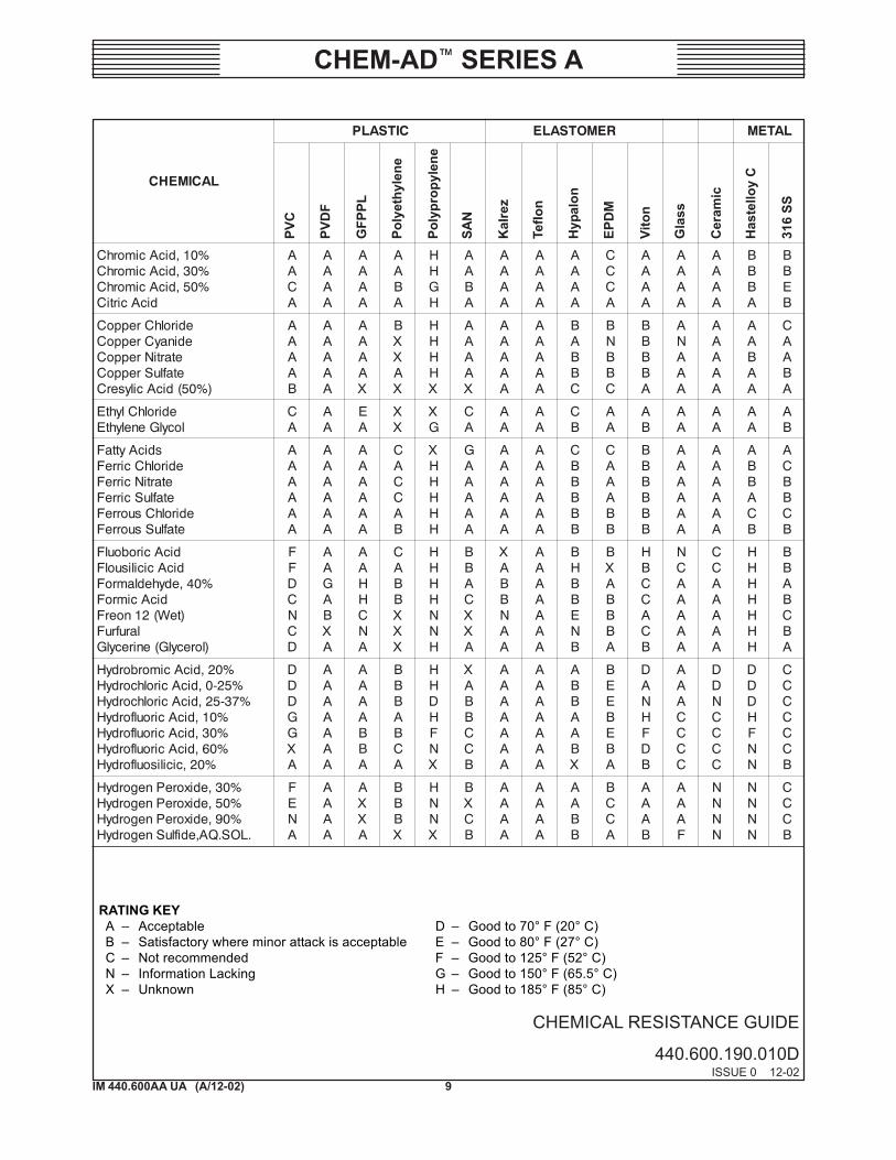
CHEMICAL RESISTANCE GUIDE
440.600.190.010AISSUE 0 12-02
INTRODUCTION
The following pages are offered as a general guide and indication of the suitability of variouselastomers and plastics in use today with a wide range of industrial chemicals. The ratingsare based, for the most part, on published literature of various plastic suppliers and elastomermanufacturers but, in some cases, they are considered the opinion of experiencedcompounders.We cannot guarantee their accuracy nor assume responsibility for use thereof. Severalfactors must always be considered in using an elastomer or plastic part in service. The mostimportant as we see them are:
TEMPERATURE OF SERVICE
Higher temperatures increase the effect of chemicals on plastic. The increase varies withthe plastic and the chemical. The compound quite stable at room temperature might fail atelevated temperature.
CONDITIONS OF SERVICE
A compound that swells badly might still function well as a static seal yet fail in any dynamicapplication.
GRADE OF PLASTIC
Many types of plastic are available in different grades that vary greatly in chemical resistance.
THE COMPOUND ITSELF
Compounds designed with certain outstanding properties may be poorer in performancewith a chemical than one designed especially for fluid resistance.
CAUTION: It is NOT recommended that USFilter/Wallace & Tiernan Chem-Ad MeteringPumps be used to handle FLAMMABLE LIQUIDS.
In light of the above factors, it is always best to TEST.
Statements and suggestions set forth herein are based upon the best information and practices known to USF/W&T. However, it shouldnot be assumed either that information is complete on the subjects covered or that all possible circumstances, safety measures,precautions, etc., have been included. These statements and suggestions are not intended to reflect state, municipal, or insurancerequirements or national safety codes; where applicable, those sources should be consulted directly. Moreover, since the conditions ofuse are beyond its control, USF/W&T makes no guarantee of results and assumed no liability in connection with the informationcontained herein.

7
CHEM-AD� SERIES A
IM 440.600AA UA (A/12-02)
CHEMICAL RESISTANCE GUIDE
440.600.190.010BISSUE 0 12-02
MATERIAL ANALYSIS OR DESCRIPTIONS
The following is typical analysis and description of the pump components named inMaterials of Construction.
LAIRETAM NOITPIRCSEDroSISYLANA
cimareC edixomunimula%99
MDPE enelyporPenelyhtE
LPPFG enelyporpylopdellif-ssalG
ssalG***naruD OiS%18,ssalGetacilisoroB 2 B%31, 2O3 aN%4, 2 K/O 2 lA%2,O 2O3
CyolletsaH :sisylanagniwollofehtfoyollaemorhc-lekcinhgiH%3srehto,%80.0C,%5.5eF,%4W,%61oM,%5.2oC,%5.51rC,%45,iN
*nolapyH MSC,enelyhteylopdetanohplusorolhC
*zerlaK MPFF,remotsaleoroulfreP
**ranyK FDVP,ediroulfenedilynivyloP
CVP edirolhclynivyloP
EP enelyhteyloP
PP enelyporpyloP
613,leetSsselniatS 613ISIA%3-2oM,%30.0S,%540.0P,%1iS,%2nM,%80.0C,%41-01iN,%81-61rC
NAS elirtinolyrcA-enerytS
*nolfeT EFTP,EFT,remylopenelyhteoroulfartetfonisernobracoroulF
*notiV ,enelyporporoulfaxehroenelyporporoulfrepdnaediroulfenedilynivforemylopoCMPEF,MKF
.oCtnoPuD.I.EfoskramedartderetsigereranotiVdna,zelraK,nolapyH,nolfeT*.cnI,aciremAhtroNmehcotAfokramedartderetsigerasiranyK**
.ttohcSfokramedartderetsigerasinaruD***

8IM 440.600AA UA (A/12-02)
CHEM-AD� SERIES A
CHEMICAL RESISTANCE GUIDE
440.600.190.010CISSUE 0 12-02
Poly
prop
ylen
e
PVC
PVD
F
GFP
PL
Poly
ethy
lene
SAN
Kal
rez
Teflo
n
Hyp
alon
EPD
M
Vito
n
Gla
ss
Cer
amic
Has
tello
y C
316
SS
RATING KEYA � Acceptable D � Good to 70° F (20° C)B � Satisfactory where minor attack is acceptable E � Good to 80° F (27° C)C � Not recommended F � Good to 125° F (52° C)N � Information Lacking G � Good to 150° F (65.5° C)X � Unknown H � Good to 185° F (85° C)
LACIMEHC
CITSALP REMOTSALE LATEM
%5,dicAcitecA%08,dicAcitecA
laicalG,dicAcitecAedirdyhnAcitecA
BCCC
DDDC
ACCA
ABBX
HEGG
AEEE
NGXA
AAAA
CEEA
ACBC
CCCC
AAAA
AAAA
HHHH
HBBB
edirolhCmunimulAediruolFmunimulAetafluSmunimulA
FFA
AAA
AAA
AXA
HHH
AAA
AXA
AAA
AAA
AAA
AAA
ACA
AXA
BGA
BEB
%01,ainommAedirolhCmuinommA
etartiNmuinommAetaflusrePmuinommAetafsohPmuinommA
etafluSmuinommA
AAAAAA
AAAAAA
AAAAAA
BAXXXA
XHHHHH
AAAAAA
AAAXXA
AAAAAA
AAAAAB
BAAAAA
AAAAAB
AAAAAA
ANAAAA
NHBXAA
ABAEAB
lohoclAlymAenilinA
ainommAauqAaigeRauqAdicAcinesrA
CCACA
ABAAA
XCAXA
XBBBX
HHXXH
CCBCA
AAAXA
AAAAA
BBBBC
BBABX
BABAA
AAAAA
AAAAN
AACCA
AAACB
edirolhCmuiraBetafluSmuiraB
reeBedyhedlazneBdicAciozneB
)etaroBmuidoS(xaroBdicAciroB
retaWenimorBdicAcirytuB
AAACAAACD
AAABAHAAA
AAACAAACA
XXBXABAXX
HHHXHHHCH
AAACEXAXB
AAAAAAAXB
AAAAAAAAA
BAACCBBCC
XXABCAABC
AAACAAAAB
ANAAAAAAA
AAAAANAAA
ANAAAAAAA
EBAABAACB
etiflusiBmuiclaCedirolhCmuiclaC
etirolhcopyHmuiclaCetafluSmuiclaC
AAAA
AAAA
AACA
AAAX
HHGH
XAAA
AAAA
AAAA
AAAA
CABB
AABA
NAAN
AABN
AAHA
BCCB
edirolhcarteTnobraCedixoiDenirolhC
dicAcinobraCdicAcitecaorolhC
maoforolhCdicAcinoflusorolhC
EBAACE
AAACAC
CEADEE
CXXXXC
CCHCCC
XXACCC
AXAAAA
AAAAAA
CCBCCC
CCCCCC
AABCBC
AAANAA
AXNAAA
AXAAAA
BCBCAB
9
CHEM-AD� SERIES A
IM 440.600AA UA (A/12-02)
CHEMICAL RESISTANCE GUIDE
440.600.190.010DISSUE 0 12-02
RATING KEYA � Acceptable D � Good to 70° F (20° C)B � Satisfactory where minor attack is acceptable E � Good to 80° F (27° C)C � Not recommended F � Good to 125° F (52° C)N � Information Lacking G � Good to 150° F (65.5° C)X � Unknown H � Good to 185° F (85° C)
Poly
prop
ylen
e
PVC
PVD
F
GFP
PL
Poly
ethy
lene
SAN
Kal
rez
Teflo
n
Hyp
alon
EPD
M
Vito
n
Gla
ss
Cer
amic
Has
tello
y C
316
SS
LACIMEHC
CITSALP REMOTSALE LATEM
%01,dicAcimorhC%03,dicAcimorhC%05,dicAcimorhC
dicAcirtiC
AACA
AAAA
AAAA
AABA
HHGH
AABA
AAAA
AAAA
AAAA
CCCA
AAAA
AAAA
AAAA
BBBA
BBEB
edirolhCreppoCedinayCreppoC
etartiNreppoCetafluSreppoC
)%05(dicAcilyserC
AAAAB
AAAAA
AAAAX
BXXAX
HHHHX
AAAAX
AAAAA
AAAAA
BABBC
BNBBC
BBBBA
ANAAA
AAAAA
AABAA
CAABA
edirolhClyhtElocylGenelyhtE
CA
AA
EA
XX
XG
CA
AA
AA
CB
AA
AB
AA
AA
AA
AB
sdicAyttaFedirolhCcirreF
etartiNcirreFetafluScirreF
edirolhCsuorreFetafluSsuorreF
AAAAAA
AAAAAA
AAAAAA
CACCAB
XHHHHH
GAAAAA
AAAAAA
AAAAAA
CBBBBB
CAAABB
BBBBBB
AAAAAA
AAAAAA
ABBACB
ACBBCB
dicAciroboulFdicAcicilisuolF
%04,edyhedlamroFdicAcimroF
)teW(21noerFlarufruF
)lorecylG(enirecylG
FFDCNCD
AAGABXA
AAHHCNA
CABBXXX
HHHHNNH
BBACXXA
XABBNAA
AAAAAAA
BHBBENB
BXABBBA
HBCCACB
NCAAAAA
CCAAAAA
HHHHHHH
BBABCBA
%02,dicAcimorbordyH%52-0,dicAcirolhcordyH%73-52,dicAcirolhcordyH
%01,dicAciroulfordyH%03,dicAciroulfordyH%06,dicAciroulfordyH
%02,cicilisoulfordyH
DDDGGXA
AAAAAAA
AAAABBA
BBBABCA
HHDHFNX
XABBCCB
AAAAAAA
AAAAAAA
ABBAABX
BEEBEBA
DANHFDB
AAACCCC
DDNCCCC
DDDHFNN
CCCCCCB
%03,edixorePnegordyH%05,edixorePnegordyH%09,edixorePnegordyH
.LOS.QA,edifluSnegordyH
FENA
AAAA
AXXA
BBBX
HNNX
BXCB
AAAA
AAAA
AABB
BCCA
AAAB
AAAF
NNNN
NNNN
CCCB

10IM 440.600AA UA (A/12-02)
CHEM-AD� SERIES A
CHEMICAL RESISTANCE GUIDE
440.600.190.010EISSUE 0 12-02
RATING KEYA � Acceptable D � Good to 70° F (20° C)B � Satisfactory where minor attack is acceptable E � Good to 80° F (27° C)C � Not recommended F � Good to 125° F (52° C)N � Information Lacking G � Good to 150° F (65.5° C)X � Unknown H � Good to 185° F (85° C)
Poly
prop
ylen
e
PVC
PVD
F
GFP
PL
Poly
ethy
lene
SAN
Kal
rez
Teflo
n
Hyp
alon
EPD
M
Vito
n
Gla
ss
Cer
amic
Has
tello
y C
316
SS
LACIMEHC
CITSALP REMOTSALE LATEM
senoteKdicAcitcaLetatecAdaeLliOgnitacirbuL
CCFF
CNAA
CAAE
XAXB
CDHH
CCAA
XAAA
AAAA
CBCB
XAAC
CFCA
AAAA
AAAA
AAAA
ANAA
edirolhCmuisengaMetartiNmuisengaMetafluSmuisengaM
dicAcielaMedirolhCenelyhteM
FFFFC
AAAAB
AAAAC
AXAXX
HHHXC
AAACC
ANAAA
AAAAA
AAAAC
ABACC
AAAAN
AAAAA
AAAAA
AAAAA
NAABA
enelahtpaNedirolhClekciN
etafluSlekciN%01,dicAcirtiN%02,dicAcirtiN%05,dicAcirtiN
suordyhnA,dicAcirtiNenezneBortiN
DFFFFNCC
AAAAHFCF
EAAAAECE
XAAABECX
DHHDDDCD
CAAFCCCC
AAAAAAAA
AAAAAAAA
CHAAFNCC
CAABCCXC
FHHAACCN
FAAAAAAA
AAANNNNA
AAAHFDDA
ANAAHFFA
staFdnasliOdicAcielO
muelOdicAcilaxO
FDCD
AACF
AEXA
XCCB
FDXF
XCCB
NAAA
AAAA
XNCH
CBXB
ADAA
AAAA
AAAA
AFXF
AAXC
lonehP%05-0,dicAcirohpsohP%001-05,dicAcirohpsohP
remyloPetahpsohpyloP
CDDBA
FAAAA
BABAA
EABAA
CHHXX
ABBAX
AAAAX
AAAAA
CAAAA
BBCAA
AHHAA
AAAAX
AAAAA
AAFXX
HFNBA
etanobraciBmuissatoPedimorBmuissatoPetanobraCmuissatoP
etarolhCmuissatoPedirolhCmuissatoPedinayCmuissatoP
etamorhciDmuissatoPedixordyHmuissatoP
etartiNmuissatoPetanagnamrePmuissatoP
etafluSmuissatoP
FFFFFFFHFFF
AAAAAAAFAAA
AAAAAAAAAAA
BBBBAXBAAAA
XHHHHHHHHFH
AAAAAAACAAA
AAAAAAAAAAA
AAAAAAAAAAA
BHHHHHHHHFH
AAABABBBBBA
XBBBBBBCHFA
NNHANFHCHFF
AANAAAACAAA
XHFFHFFHFAF
BFFFNAAHFHH

11
CHEM-AD� SERIES A
IM 440.600AA UA (A/12-02)
CHEMICAL RESISTANCE GUIDE
440.600.190.010FISSUE 0 12-02
RATING KEYA � Acceptable D � Good to 70° F (20° C)B � Satisfactory where minor attack is acceptable E � Good to 80° F (27° C)C � Not recommended F � Good to 125° F (52° C)N � Information Lacking G � Good to 150° F (65.5° C)X � Unknown H � Good to 185° F (85° C)
Poly
prop
ylen
e
PVC
PVD
F
GFP
PL
Poly
ethy
lene
SAN
Kal
rez
Teflo
n
Hyp
alon
EPD
M
Vito
n
Gla
ss
Cer
amic
Has
tello
y C
316
SS
LACIMEHC
CITSALP REMOTSALE LATEM
spaoSetatecAmuidoSetanimulAmuidoSetanobraciBmuidoS
etaflusiBmuidoSetiflusiBmuidoSetanobraCmuidoS
etarolhCmuidoSedirolhCmuidoSedinayCmuidoS
etahpsohpatemaxeHmuidoS%02,edixordyHmuidoS%05,edixordyHmuidoS
etirolhcopyHmuidoSetartiNmuidoSetaciliSmuidoSetafluSmuidoSedifluSmuidoS
FFBFFFFFFFFDNFFFFF
AAAAAAAAAAAHFAAAAA
AAAAAAAAAACAAEAAAA
EAAAAAAAAXAABAAAAA
HHXHHXHHHHXHHHHHHH
AAAAAAAAAAXBBAAAAA
AAAAFFAAAXAAAAAAAA
AAAAAAAAAAAAAAAAAA
AAAAAAAAAAAAAAAAAA
DAAAAAAAAAAANAAAAA
ANAAAAAAAAAADHDAAA
AAXGGCFNFAXCCGANAX
AAAAAANAAAACCAAAAA
AFXFFXFFFAXAAFFFAH
AAAAAAAFNAXAACAHAB
edirolhCcinnatSdicAciraetS
stnevloSsdraddotS%01-0,dicAcirufluS%57-01,dicAcirufluS%59-57,dicAcirufluS%001-59,dicAcirufluS
FFCDNNC
AAXAAAN
AEXAAEE
ACXAEEE
HXXHFNN
ACXCCCC
XAXAGEE
AAAAAAA
NXXACCC
NBCACCC
AAAAAAH
AAAAAAA
AAXAHFF
HXXAFFF
CAANCCC
dicAcinnaTsrouqiLgninnaT
dicAciratraTenelyhteorolhcirTetahpsohplysercirT
FFFCC
AAAAA
AAAEX
BAXCX
HXHCX
XXCXX
AXADX
AAAAA
AXDCC
BCDCB
AAAAA
AAHAX
AAAAA
HXAAX
FAANX
aerUrageniV
)dicA(rouqiLetihWedirolhCcniZ
etafluScniZetahpsohpohtrOcniZ
AAAAAA
AAAAAA
AAXAAA
XAXAAA
HHXHHX
XACAAX
NAXAAX
AAAAAA
NAXBAA
XAXAAX
CBABAA
AAAAAN
AAAAAX
AAXADX
BAABAA

12IM 440.600AA UA (A/12-02)
CHEM-AD� SERIES A

13
CHEM-AD� SERIES A
IM 440.600AA UA (A/12-02)
SECTION 2 - INSTALLATIONS
List of Contents
PARA. NO.
General Information ................................................. 2.1Unpacking ................................................................. 2.2Mounting the Pump .................................................. 2.3Dimensions ............................................................... 2.4Connection of Suction and Return Line with
Duo Hose ............................................................... 2.5Connection of Metering Line ................................... 2.6Connection to Optional Suction Pipe Assembly ...... 2.7Electrical Connection ............................................... 2.8Socket Connector, PIN Assignment ......................... 2.9
14IM 440.600AA UA (A/12-02)
CHEM-AD� SERIES A
2.1 General Information
To provide satisfactory service, the metering pump must be installed inaccordance with the instructions that follow. Operational difficulties, lackof accuracy, and possible damage to the pump mechanism may occur ifthese instructions are not followed properly.
CAUTION: Do not run Chem-Ad Series A pump dry.
2.2 Unpacking
When the pump is unpacked, check all items inside the box. There arebags of various connection parts, including the Duo tubing supplied withthe pump. Make sure that no parts are discarded with the packaging material.Whenever possible, unpack the equipment at the installation site.
2.3 Mounting the Pump
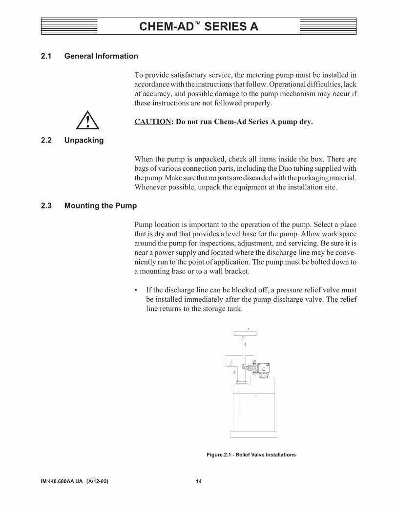
Pump location is important to the operation of the pump. Select a placethat is dry and that provides a level base for the pump. Allow work spacearound the pump for inspections, adjustment, and servicing. Be sure it isnear a power supply and located where the discharge line may be conve-niently run to the point of application. The pump must be bolted down toa mounting base or to a wall bracket.
� If the discharge line can be blocked off, a pressure relief valve mustbe installed immediately after the pump discharge valve. The reliefline returns to the storage tank.
Figure 2.1 - Relief Valve Installations
!

15
CHEM-AD� SERIES A
IM 440.600AA UA (A/12-02)
� If discharging into a negative head, an anti-siphon valve must beinstalled at the discharge line to prevent siphoning of the processfluids into the point of application. The installation of a solenoidvalve may be required to prevent process fluids from siphoning whenthe pump is not operating.
Figure 2.2 - Installation With Anti-Siphon and Solenoid Valve
� If the storage tank is higher than the pump, such that the processfluid may run freely through the pump, a back pressure valve mustbe installed at the discharge of the pump. The discharge pressuremust be at least 15 psi (1 bar) higher than the suction pressure.
OPENDISCHARGE
Ap>15PSIMUST NOTCONTACT LIQUID
BACK PRESSUREVALVE
Figure 2.3 - Flooded Suction Installations
16IM 440.600AA UA (A/12-02)
CHEM-AD� SERIES A
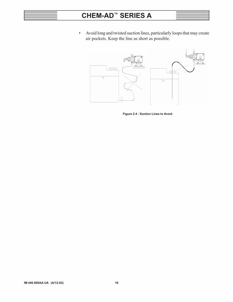
� Avoid long and twisted suction lines, particularly loops that may createair pockets. Keep the line as short as possible.
Figure 2.4 - Suction Lines to Avoid

17
CHEM-AD� SERIES A
IM 440.600AA UA (A/12-02)
2.4 Dimensions
Wall bracket (AJE4896) is a convenient way to mount the pump on thewall. Four #10 x 24 x 3/4" long screws (P41044) are needed to secure thepump. Position the pump for easy access to the liquid end for service andthe front face for the control. Figure 2.5 shows the pump dimensions.
4-11/16"(119mm)
5-5/8"(143mm)
3-1/4"(83.5mm)
3-11/16"(93mm)
4-3/4"(121.5mm)
DISCHARGE CONNECTION1/4" OD x 1/8" ID
TUBING
1-1/2"(37mm)
8-9/16"(218mm)
8-11/16"(220mm)
8-3/4"(221mm)
7/8"(22mm)
SUCTION CONNECTION1/4" ID x 3/8" ODTUBING
RETURN CONNECTION1/4" ID x 3/8" OD
TUBING
5"(126.6mm)
3-1/8"(80mm)
2-5/8"(67mm)
19/32"(15mm)
(4) MOUNTING HOLESØ3/16" (4.5mm)
Figure 2.5 - Dimensions, Series A
18IM 440.600AA UA (A/12-02)
CHEM-AD� SERIES A
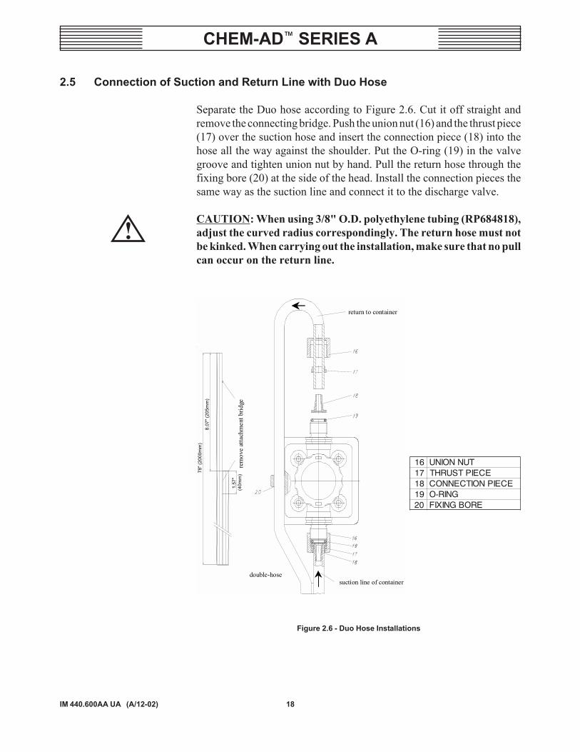
2.5 Connection of Suction and Return Line with Duo Hose
Separate the Duo hose according to Figure 2.6. Cut it off straight andremove the connecting bridge. Push the union nut (16) and the thrust piece(17) over the suction hose and insert the connection piece (18) into thehose all the way against the shoulder. Put the O-ring (19) in the valvegroove and tighten union nut by hand. Pull the return hose through thefixing bore (20) at the side of the head. Install the connection pieces thesame way as the suction line and connect it to the discharge valve.
CAUTION: When using 3/8" O.D. polyethylene tubing (RP684818),adjust the curved radius correspondingly. The return hose must notbe kinked. When carrying out the installation, make sure that no pullcan occur on the return line.
return to container
suction line of container
rem
ove
atta
chm
ent b
ridge
double-hose
Figure 2.6 - Duo Hose Installations
61 TUNNOINU71 ECEIPTSURHT81 ECEIPNOITCENNOC91 GNIR-O02 EROBGNIXIF
78" (
2000
mm
)8.
07" (
205m
m)
1.57
" (4
0mm
)!

19
CHEM-AD� SERIES A
IM 440.600AA UA (A/12-02)
2.6 Connection of Metering Line
Cut off the tubing straight, push union nut (16), and plastic ferrule (21)over the tubing. Attach the tubing into the connection piece (22) all the wayin and screw in the union nut tightly by hand. Adjust the angle to a conve-nient position by loosening and tightening the nut (23). See Figure 2.7.
Figure 2.7 - Metering Line Installation
2.7 Connection to the Optional Suction Pipe Assembly
Suction pipe assemblies with level switch, pre-warning, and empty sig-nals are available for use with this pump. They are completely wired andready to connect to the pump socket connector. A foot valve and strainerare built into the pipe. All the necessary connections for the Duo hosecome with the suction pipe. Depending on the storage tank height, thesuction pipes are available in different lengths. Select the length that ishigher than the storage tank by approximately six inches. These pumpsmust not run dry, therefore the use of the suction pipe with a connectionto stop the pump when the storage tank is empty is highly recommended.Refer to Section 6 - Preventive Maintenance Kits and Accessories formore information on these parts..
2.8 Electrical Connection
A six-foot cable with a three-prong grounded plug, US standard, is pro-vided with the USA version of the Chem-Ad Series A pumps. It can beplugged into a US standard outlet with 115 VAC, single phase, 30 amps.For the metric version, a cable with a EURO plug is provided.
NOTE: The electrical connections should comply with local electricalcodes.
23
22 21 16

20IM 440.600AA UA (A/12-02)
CHEM-AD� SERIES A
2.9 Socket Connector, PIN Assignment
Included in the bag of loose parts are the socket terminals for the socketconnections. They are keyed to connect properly to the correct PIN in thesocket connector. Look at the socket terminal and check for the availablePIN connections. Connector I has 3-PIN connections, Connector II has 5-PIN connections and Connector III has 4-PIN connections. Wire accord-ingly.
Figure 2.8 - Socket Connector
2.9.1 Connector I
� Tank empty signal input, PIN #3 and PIN #4 (Dry contact). Contactis open; the pump is stopped.
� Pre-warning signal input, PIN #1 and PIN #4 (Dry contact). Contactis open pre-warning, but the pump continues to operate.
Figure 2.9 - Connector I
1 nworb,tupnilangisevreseR
3 eulb,tupnilangisytpmE4 kcalb,)nommoc(dnuorG
E11/M11 E30/M30
I II IIII II III

21
CHEM-AD� SERIES A
IM 440.600AA UA (A/12-02)
2.9.2 Connector II
� Remote On/Off, PIN #3 and PIN #4 (Dry contact). Contact is closed;the pump is running.
NOTE: If the remote On/Off is not used, PIN # 3 and PIN # 4 must bebridged.
� Pulse Input, PIN #2 and PIN #4 (Dry contact). Contact is closed; apulse is processed.
Minimum pulse length is 15 milli-seconds = 1 strokeMaximum pulse is 122 pulses per min. = Continuous running for 50or 60 Hz
� 5V output, PIN #1 and PIN #4. Connect to sensor requiring 5VDCpower with maximum load of 80mA.
� 0/4-20mA input, PIN #5 and PIN #4. Connect to equipment with 0/4-20mA output.
Figure 2.10 - Connector II
1 nworb,V5tuptuO
2 etihw,tupnIesluP3 ffO/nOetomeR4 kcalb,)nommoc(dnuorG5 Am02-4/0tupnI

22IM 440.600AA UA (A/12-02)
CHEM-AD� SERIES A
2.9.3 Connector III
� Empty signal output, PIN #1 and PIN #2 (Floating relay contact).Contact is closed when pump is in fault mode or tank is empty. Whenstorage tank is almost empty (pre-warning), relay output contact ison and off with every stroke with local flashing red LED.
NOTE: Maximum load is 24V AC/DC, 3 amps External 24V AC/DC,power supply required.120/240V AC/DC, 3 amps power supply can be used, however, PIN #3and PIN #4 (stroke signal output) must not be used for safety reasons.Use only 2-wire cable.
� Stroke signal output, PIN #3 and PIN #4.1 pulse = 1 stroke
NOTE: Maximum load is 24VDC, 300mA. External 24VDC powersupply required.This output, PIN #3 and PIN #4, can be directly connected to Connec-tor II, PIN #2 and PIN #4, of another Chem-Ad pump.
Figure 2.11 - Connector III
NOTE: The color code allocation applies only to the standard cablesupplied from the factory.
1 nworb,tuptuOlangiSytpmE
2 etihw,tuptuOlangiSytpmE3 )+(eulb,tuptuOlangiSekortS4 )-(kcalb,tuptuOlangiSekortS

23
CHEM-AD� SERIES A
IM 440.600AA UA (A/12-02)
SECTION 3 - OPERATION
List of Contents
PARA. NO.
Preparation for Operation ......................................... 3.1Theory of Operation ................................................. 3.2Effect of Back Pressure on Capacity ........................ 3.3Capacity in Relation to Stroke Length ..................... 3.4

24IM 440.600AA UA (A/12-02)
CHEM-AD� SERIES A
3.1 Preparation for Operation
a. Fill the container with solution.
WARNING: TO AVOID POSSIBLE SEVERE PERSONAL IN-JURY, USE EXTREME CARE TO AVOID CONTACT WITH THEMATERIAL. CONSULT CHEMICAL SUPPLIER FOR INSTRUC-TIONS ON THE PREPARATION OF SOLUTIONS AND HAN-DLING OF CHEMICALS.
b. Start the pump, turn the mechanical stroke adjustment to �0�% andwait until the re-circulating line is primed completely as seen throughthe tubing. Then turn the stroke to 100% until the discharge line isfull. Keep the speed (stroke frequency) high and adjust the requireddosage by the mechanical stroke adjustment. If the installation isflow proportional and the pump is controlled by a 4 - 20 mA signal,do the adjustment of dosage in local mode.
c. Read the stroke scale setting of the knob. Two turns of the knob isfrom 0% to 100%. Between 0% to 50% setting is direct reading onthe knob graduations. Between 50% to 100% setting, add 50% to theknob graduation reading.
Figure 3.1 - Stroke Length Adjustment Scale
3.1.1 Metering Capability
The reproducible metering accuracy is ± 2% of full scale over 5:1 rangewith the manually adjustable stroke length knob. Stroke length settingfrom 20% and below is not recommended. It is preferable to make thestroke length adjustment from low setting to high setting, that is, withclockwise rotation of the knob.
With the E30/M30 control option the frequency of the stroke can beadjusted infinitely from 0 to 144 spm (60 Hz) or 0 to 122 spm (50 Hz) inpercent reading by a rotary knob (with the control switch in local posi-
!

25
CHEM-AD� SERIES A
IM 440.600AA UA (A/12-02)
tion). When the control switch is in remote position, the stroke frequencyis controlled by 4 - 20 mA signal or pulse, disabling the rotary knob.
3.1.2 Strength of Solution
Appropriate dilution of the solution will modify the concentration andtherefore the feed rate. This will increase or decrease the amount of solu-tion to be pumped per unit time. Adjusting the solution concentration canmatch the feed rate with the pump�s capabilities and enhance the meteringrepeatability.
3.1.3 Calibrating the Pump
Perform the calibration on the suction side of the pump against actual backpressure. The re-circulating line requires a different set-up than an ordi-nary pump using a calibration column. The discharge from the re-circu-lating line must be directed to the calibration column for the duration ofthe test. In addition, direct the liquid flow so that it will not create distur-bances to the liquid level in the column. If a back pressure valve is in-line,connect the discharge line after the valve or rig up a temporary dischargeline with back pressure valve in-line. Proceed as follows when using anyof the following calibration columns:
100 ML AAC2543250 ML AAC2546500 ML AAC2549
a. Fill up the calibration column over the �0� line.
b. Close the suction valve and open the valve to the calibration column.
c. Re-set the stopwatch to zero, start the pump, and watch the liquidlevel as it goes down.
d. As soon as the liquid level hits the �0� line, start the stopwatch.
e. Keep an eye on the liquid level and the stopwatch.
f. Time for exactly one minute and then check the liquid level.
g. The number corresponding to the graduation is the flow in GPH orML/MIN.
If the flow rate for one minute is too small and does not show very wellin the column graduation, do the test for a longer time period. Use the ML
26IM 440.600AA UA (A/12-02)
CHEM-AD� SERIES A
graduation to get the volume in milliliters and divide it by the run time inminutes to get milliliters per minute (ML/MIN). Multiply ML/MIN by0.01585 to get GPH.
3.2 Theory of Operation
Chem-Ad Series A is a mechanically actuated diaphragm metering pumpdriven by a synchronous motor. A flat diaphragm between the pump headand the pump housing moves backward and forward to produce a pump-ing action through two ball checks inside the pumping chamber. A plunger,connecting rod, and a fix eccentric combination produce the reciprocatingmotion that moves the diaphragm. In as much as the eccentric is fixed, thediaphragm moves the same distance/stroke all the time.
Attached at the front of the diaphragm (3) is a ceramic piston (see Figure3.2). The piston/cylinder unit (5) is where the metering takes place. Whenthe diaphragm is at the suction stroke (moving back), the suction valve (4)opens to admit the liquid into the pump chamber. Simultaneously vacuumdevelops in the compression chamber of the metering piston/cylinder unit(5) until the piston uncovers the hole (6) and at that time the liquid entersthe compression chamber. On the return stroke of the piston, the liquid inthe compression chamber is pushed back out through the hole (6) until thepiston covers the hole. All the liquid trapped is then discharged throughdischarge valve (7) while the excess liquid returns to the storage tankthrough discharge valve (8). The location of hole (6) determines howmuch liquid is trapped and hence metered. By turning the knob (9) thehole can be positioned in relation to the piston and is calibrated to meterfrom 0 flow (no liquid trapped) to 100% (all liquid trapped).
This system provides for the elimination �air binding� in pumping liquidthat emits gas, such as sodium hypochlorite and hydrogen peroxide, bycontinuously purging air through the re-circulating line.

27
CHEM-AD� SERIES A
IM 440.600AA UA (A/12-02)
1 ROTOMSUONORHCNYS2 RAEGCIRTNECCE-DOR3 MGARHPAID4 EVLAV
5NOTSIPGNIRETEM
TINUREDNILYC6 ELOHNOITCEPSNI7 EVLAV8 EVLAVNRUTER9 TNEMTSUJDAEKORTS
Figure 3.2 - Pump Structure with De-gassing Head

28IM 440.600AA UA (A/12-02)
CHEM-AD� SERIES A
3.3 Effect of Back Pressure on Capacity
3.3.1 USA Version - Capacity vs. Back Pressure

29
CHEM-AD� SERIES A
IM 440.600AA UA (A/12-02)
3.3.2 EURO Version - Capacity vs. Back Pressure
F ö F ö F ö
STROKE LENGTH
DEL
IVER
Y C
APAC
ITY
l/h

30IM 440.600AA UA (A/12-02)
CHEM-AD� SERIES A
3.4 Capacity in Relation to Stroke Length
All metering capacity information relates to measurements using water at68° F (20° C) with a constant power supply and warmed-up pump. Formetering accuracy, it is recommended that the lowest stroke length settingbe 20%.
3.4.1 USA Version - Capacity vs. Stroke Length

31
CHEM-AD� SERIES A
IM 440.600AA UA (A/12-02)
3.4.2 EURO Version - Capacity vs. Stroke Length
METERING BACK PRESSURE BAR
DEL
IVER
Y C
APAC
ITY
l/h

32IM 440.600AA UA (A/12-02)
CHEM-AD� SERIES A

33
CHEM-AD� SERIES A
IM 440.600AA UA (A/12-02)
SECTION 4 - SERVICE
List of Contents
PARA. NO.
General Information ................................................. 4.1Periodic Cleaning ..................................................... 4.2Periodic Preventive Maintenance ............................. 4.3Corrective Maintenance............................................ 4.4Troubleshooting ........................................................ 4.5Warning Summary .................................................... 1 Page
34IM 440.600AA UA (A/12-02)
CHEM-AD� SERIES A
NOTE: This Instruction Book assumes that the customer has theright tools that are necessary to service the pump safely and effi-ciently. The customer must also know how to use them properly.There are certain notes, cautions, and warnings included in the book;each one is there for a specific purpose. NOTES provide added infor-mation that will help complete a particular procedure. CAUTIONSare given to prevent an error that could damage the pump. WARN-INGS remind the user to be especially careful in those areas wherecarelessness can cause personal injury.
WARNING: TO AVOID POSSIBLE SEVERE PERSONAL INJURYOR EQUIPMENT DAMAGE FROM BEING SPRAYED WITH LIQ-UID UNDER PRESSURE, REFER TO DETAILED INSTRUCTIONON RELIEVING PRESSURE AND DRAINING PRIOR TO DIS-ASSEMBLY OF PIPE CONNECTIONS.
4.1 General Information
4.1.1 Routine Maintenance
Routine maintenance of the metering pump consists of two operations:
� Periodic cleaning: To remove contaminants and deposits formed onparts in contact with the solutions.
� Periodic preventive maintenance: To disassemble, inspect, clean, andreplace parts as recommended.
4.1.2 Corrective Maintenance
Corrective maintenance is performed (as required, at unscheduled inter-vals) to correct a discrepant operating or non-operating condition. Atroubleshooting table (refer to Table 4.2) lists possible fault conditionsand corrective actions as a guide for service personnel.
4.2 Periodic Cleaning
4.2.1 Cleaning Pumping Head Parts
If difficulty is encountered in pumping the solution where hard water isknown to have been used in the preparation of the solution, remove thepumping head parts for cleaning (refer to paragraph 4.4.1, RemovingPump from Service and Replacement of Valves, Pump Head, Diaphragm,and Casing Bellows, for head removal). The effects of hard water areindicated by a white coating on all parts in contact with the solution. This
!

35
CHEM-AD� SERIES A
IM 440.600AA UA (A/12-02)
coating is most easily removed by soaking the parts in 5% hydrochloricacid, commonly obtainable in drug store. The commercial grade of hydro-chloric acid�known as muriatic acid�is also suitable for this purpose.Where the above condition is known to exist, pump the acid solution tothe pump head for approximately five minutes.
WARNING: TO AVOID POSSIBLE SEVERE PERSONAL IN-JURY, USE EXTREME CARE TO AVOID CONTACT WITH THEMATERIAL. CONSULT CHEMICAL SUPPLIER FOR INSTRUC-TIONS ON THE PREPARATION OF SOLUTIONS AND HAN-DLING OF CHEMICALS.
4.2.2 Cleaning Clogged Solution Tube
Where the solution joins water being treated and that water containsconsiderable hardness, there may be a deposit formed inside the solutiontube at the point of application. In time, this can completely plug tube andthe deposit must be removed. The best method is by dissolving the depositas described in paragraph 4.2.1, Cleaning Pumping Head Parts. Wherethis condition is known to exist, clean the solution tube as a part of routinemaintenance.
4.3 Periodic Preventive Maintenance
To minimize unscheduled shut-down and ensure maximum service life,perform periodic maintenance at specified intervals while the equipmentis in satisfactory condition. Table 4.1 lists the interval, maintenance opera-tion, and preventive maintenance kits required. Before starting the work,ensure that the appropriate preventive maintenance kits are in stock. Referto Section 6 - Preventive Maintenance Kits and Spare Parts List for theappropriate maintenance kit.
NOTE: Although all parts are designed for long service life, it isrecommended that routine maintenance be performed to safeguardagainst unexpected downtime.
!

36IM 440.600AA UA (A/12-02)
CHEM-AD� SERIES A
Table 4.1 - Scheduled Maintenance Index
LAVRETNI NOITAREPOECNANETNIAMEVITNEVERP
TIKECNANETNIAM
fislavretniretrohs,ylretrauQyadasruoh42gninnur
egrahcsiddnanoitcuStcepsnI:skaelrofsnoitcennoc
1.4erugiFotrefeR)32,02,61(stuNnoinU
erehtfi(daehpmupno)72(eloHniarD)dekcarcsimgarhpaidehtkaelsi63-62oteuqrot,)62(swercSdaeH
)mN4-3(sbl-hcni
:dedeenerastrapfIMProf6noitceSotrefeR
.stiKtiKnoitcennoCehtredrO)noisreVORUEroASU(
fosruoh0004yrevEnoitarepo
mgarhpaidehtegnahC 7024BAA-4Adna1A3124BAA-2A0124BAA-3A
yllaunnA notsip/rednilycdnastesevlavllaegnahCylbmessa
MProf6noitceSotrefeRstiK
tiKdaeHehtredrO
Figure 4.1 - Parts to Check for Leaks
16
26
27
16
7 23
20

37
CHEM-AD� SERIES A
IM 440.600AA UA (A/12-02)
4.4 Corrective Maintenance
WARNING: TO AVOID CONTACT WITH THE MATERIAL ANDPOSSIBLE SEVERE PERSONAL INJURY WHEN SERVICINGHEADS AND/OR VALVES, FOLLOW THE PROCEDURES INTHIS SECTION FOR DISASSEMBLY.
WARNING: TO AVOID POSSIBLE SEVERE PERSONAL IN-JURY, USE EXTREME CARE TO AVOID CONTACT WITH THEMATERIAL. WHEN HANDLING HAZARDOUS MATERIAL,OBSERVE ALL SAFETY PRECAUTIONS RECOMMENDED BYTHE MATERIAL MANUFACTURER/SUPPLIER.
CAUTION: To prevent possible equipment damage, the solution mustnever be allowed to freeze in the pump. If freezing conditions arepresent when the pump is shut-off, drain the pump head and allsolution lines prior to shut-off.
Corrective maintenance is performed as required to correct a discrepantoperating or non-operating condition. A troubleshooting table (refer toTable 4.2) is provided to guide service personnel in diagnosing and cor-recting most common troubles.
Routine maintenance procedures includes the elimination of solution leakswhen they are found, to avoid corrosion damage. Flush away spilledsolution with water and wipe the parts clean and dry.
Maintain gasketed joints in good condition. Keep an adequate supply ofgaskets and O-rings available so that repair of leaks can be accomplishedwithout delay. It is a good practice to discard used gaskets and O-rings,replacing them with new material each time a joint is broken.
4.4.1 Removing Pump from Service and Replacement of Valves, Pump Head, Dia-phragm, and Casing Bellows
WARNING: TO AVOID POSSIBLE SEVERE PERSONAL IN-JURY, USE EXTREME CARE TO AVOID CONTACT WITH THEMATERIAL. OBSERVE ALL SAFETY PRECAUTIONS, ANDUTILIZE APPROPRIATE PROTECTIVE CLOTHING AND EYEPROTECTION WHEN HANDLING HAZARDOUS MATERIAL.
Procedures for the assembly and disassembly of parts for pump mainte-nance are referenced in the following paragraph.
!
!
!
!

38IM 440.600AA UA (A/12-02)
CHEM-AD� SERIES A
4.4.2 Draining System of Hazardous Material
WARNING: TO AVOID POSSIBLE SEVERE PERSONAL INJURYFROM BEING SPRAYED BY LIQUID UNDER PRESSURE, AL-LOW THE SYSTEM TO DRAIN FULLY BEFORE ATTEMPT-ING TO DISASSEMBLE PIPING AND REMOVE VALVES AND/OR HEAD.
a. Disconnect power from the pump or unplug the pump.
b. Close the discharge shutoff valves of the metering line and the re-circulating line.
c. For flooded suction, close the suction shutoff valve to prevent thebackflow of liquid when suction lines are disconnected.
d. Open the suction drain valve and drain the suction line of liquid.
e. Open the discharge drain valve of both the metering line and the re-circulating line to relieve pressure and drain the line.
f. The tubing connections can now be disconnected.
4.4.3 Replacement of the Re-circulating Valves
WARNING: TO AVOID POSSIBLE SEVERE PERSONAL IN-JURY, USE EXTREME CARE TO AVOID CONTACT WITH LIQ-UID PRESENT IN THE PUMP HEAD. ALLOW THE SUCTIONVALVE TO FALL INTO A SUITABLE CONTAINER AND CATCHTHE LIQUID.
WARNING: TO AVOID POSSIBLE SEVERE PERSONAL IN-JURY, USE EXTREME CARE TO AVOID CONTACT WITH THELIQUID PRESENT BETWEEN THE DISCHARGE DRAIN VALVEAND THE UNIT BELOW. FLUSH ANY SPILLED LIQUID IM-MEDIATELY.
a. Disconnect the discharge and suction connections per paragraph 4.4.2.
b. Unscrew the suction and discharge valves.
c. Wash the valves thoroughly with water to remove any chemical.
d. The valve can be disassembled to check for any dirt trapped insideby removing the bottom seat. They can be re-used after cleaning and
!
!
!

39
CHEM-AD� SERIES A
IM 440.600AA UA (A/12-02)
if there is no evidence of defect. Refer to Figure 4.2 for the valveassembly drawing.
CAUTION: Use a small pair of pliers to carefully twist the seat out.Be careful not to mar the seat's outside diameter. Position the valvevertically to prevent the parts from falling.
e. Inspect all the parts for any defects. Replace the whole valve if anypart is defective. The parts are available as a complete assembly inthe PM Kit.
f. For re-assembly look for the direction of the arrow. The arrow mustpoint upward.
g. To install the discharge valve, position the O-ring (22) at the bottomof the pump head discharge opening.
h. Position the O-ring (21) at the valve shoulder and screw it in hand-tight; watch for the direction of the arrow.
i. To install the suction valve, position two O-rings onto the valve, oneat the valve shoulder (21) and the other at the valve seat (20). Watchfor the direction of the arrow.
Figure 4.2 - Valves and Diaphragm Assembly
34 38 39 35 36 32
33737
30
31
29
22
21
5
21
22
!

40IM 440.600AA UA (A/12-02)
CHEM-AD� SERIES A
4.4.4 Replacement of Re-circulating Diaphragm and Casing Bellows
a. Drain the pump head of chemical and disconnect all the tubing linesper paragraph 4.4.2
b. Remove the suction and discharge valves of the re-circulating lineper paragraph 4.4.3
c. Loosen the metering head screws and pull out the pump head abso-lutely straight. Refer to Figure 4.2.
CAUTION: The head must be pulled straight out until the piston (5)clears the cylinder (34). The piston (5) remains connected to the dia-phragm (29), but may fall while pulling the head.
d. Remove the ceramic piston (5) sideways out of the coupling of thediaphragm unit (29).
e. Unscrew the diaphragm unit (29) and remove the intermediate plate(30).
f. Remove the bellow (31) and exchange for the new one.
g. Gently screw in the diaphragm unit (29) until it stops.
NOTE: The leakage drain connection of the intermediate plate mustbe pointing downward.
h. Re-insert the piston (5) into the cylinder unit (34) and carefully pushthe pump head absolutely straight.
i. Secure with four metering head screws and tighten to 26-36 inch-lbs(3-4 Nm) evenly and diagonally.
j. The metering head screws must be re-torqued to 26-36 inch-lbs (3-4Nm) after running the pump for 24 hours.
4.4.5 Replacement of Ceramic Piston/Cylinder Unit
a. Remove the head assembly per paragraph 4.4.4, procedures �a� to�d�.
b. Unscrew valve nipple (32). Refer to Figure 4.2.
!

41
CHEM-AD� SERIES A
IM 440.600AA UA (A/12-02)
CAUTION: Watch for the spring (35) and valve ball (7) as they mightfall out.
c. Remove washer (33), valve ball (7), and spring (35).
d. Push the ceramic cylinder unit (34) at the diaphragm end.
e. Insert a new unit.
NOTE: Cylinder and piston are one unit and are replaced as anassembly only.
f. Replaced O-rings (36, 37, 38, and 39).
g. Re-install the valve nipple (32) with the valve ball (7) and spring(35) in proper position.
4.4.6 Replacement of Metering Valve
a. Drain the pump head of chemical and disconnect the metering lineper paragraph 4.4.2
b. Unscrew the union nut (40) that holds the connection assembly. Re-fer to Figure 4.2.
c. Unscrew the valve nipple (32) and remove valve ball (7) and spring(35).
d. Replace O-rings (36 and 37), valve ball (7), and spring (35).
e. Install the new metering valve assembly with new valve ball (7) andnew spring (35) in proper position.
4.4.7 Setting the Mechanical Stroke Adjustment Calibration
The pump is calibrated at the factory in accordance with the characteristiccurves shown in Section 3, paragraph 3.4 and at maximum back pressure.The stroke adjustment basic setting can be determined as follows:
a. Turn the pump on and make sure that the flow of liquid in the meter-ing line (tubing) can be seen clearly.
b. Turn the stroke adjustment knob (9) counter-clockwise until there isno liquid flow in the metering line. Refer to Figure 4.3.
!
42IM 440.600AA UA (A/12-02)
CHEM-AD� SERIES A
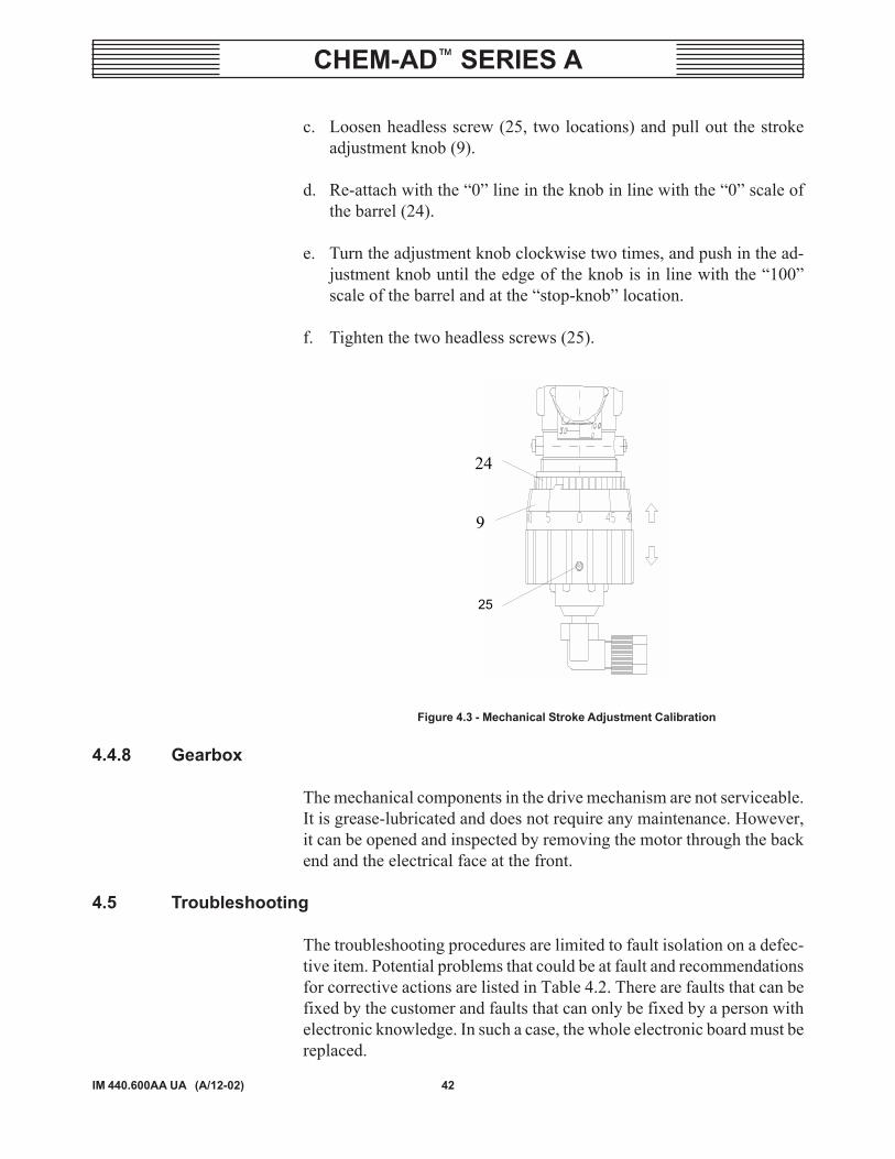
c. Loosen headless screw (25, two locations) and pull out the strokeadjustment knob (9).
d. Re-attach with the �0� line in the knob in line with the �0� scale ofthe barrel (24).
e. Turn the adjustment knob clockwise two times, and push in the ad-justment knob until the edge of the knob is in line with the �100�scale of the barrel and at the �stop-knob� location.
f. Tighten the two headless screws (25).
24
9
25
Figure 4.3 - Mechanical Stroke Adjustment Calibration
4.4.8 Gearbox
The mechanical components in the drive mechanism are not serviceable.It is grease-lubricated and does not require any maintenance. However,it can be opened and inspected by removing the motor through the backend and the electrical face at the front.
4.5 Troubleshooting
The troubleshooting procedures are limited to fault isolation on a defec-tive item. Potential problems that could be at fault and recommendationsfor corrective actions are listed in Table 4.2. There are faults that can befixed by the customer and faults that can only be fixed by a person withelectronic knowledge. In such a case, the whole electronic board must bereplaced.

43
CHEM-AD� SERIES A
IM 440.600AA UA (A/12-02)
Table 4.2 - Troubleshooting
NOITIDNOCTLUAF ESUACELBISSOP NOITCAEVITCERROC
SEODPMUPGNIRETEMDELNEERG,KROWTON
.FFO
rorewopon,egatlovtcerrocnI.nwolbesuf
gulproegamadelbacniaM.evitcefed
.elbacdnaylppusrewopkcehC
EMIRPTONSEODPMUP)ENILGNITALUCRIC-ER(
KCABTUOHTIWNEVEEKORTSXAM,ERUSSERP
.DEEPSDNA
sevlavegrahcsiddnanoitcuS.yrdrotridoteudkcuts,skael
.sevlavehtesnirdnaevomeR
pmupehttasetalumuccasaG.enilnoitcusdnadaeh
.noitativacrofkcehCdedoolffiresirdetnevallatsnI
.noitcusyllaicepse,diuqilehtetuliD
.etirolhcopyHmuidoS
ffo-tuhsegrahcsiddnanoitcuS.desolcsevlav
.sevlavnepO
.deggolcsireniartS .reniartsnaelC
.enilnoitcusniegakaelsierehT .skaelriaperdnakcehC
TNIOPTALACIMEHCON,NOITACILPPAFOSIPMUPHGUOHT
-ER(GNIPMUP.)ENILGNITALUCRIC
.hgihootsierusserP niamehttaerusserpehtkcehC.enil
.nrowsiylbmessanotsip/rednilyC .ylbmessanotsip/rednilycecalpeR
mgarhpaidmorfegagnesidnotsiP.gnilpuoc
rofkcehcdnadaehevomeR.notsiprognilpuocnekorb
gniveilersievlavfeilererusserP.evitcefedro)deppiuqefi(
otevlavfeilererusserptsujdA.erusserpfeilerreporp
erusserpehtriaperroegnahC.evitcefedfievlavfeiler
SIDAEHGNIRETEMSIDIUQILDNAGNIKAEL
NEEWTEBGNIGREMEDNADAEHEHT
.ETALPETAIDEMRETNI
.esoolsidaehgnireteM swercsdaehehtnethgiT4-3(sbl-hcni63-62otyllanogaid
.)mN
.erutpurmgarhpaiD .mgarhpaidecalpeR
GNIKAELSIDIUQILEHTHGUORHT
ETALPETAIDEMRETNI.ENILNIARD
.erutpurmgarhpaiD .mgarhpaidecalpeR

44IM 440.600AA UA (A/12-02)
CHEM-AD� SERIES A
Table 4.2 - Troubleshooting (Cont'd)
NOITIDNOCTLUAF ESUACELBISSOP NOITCAEVITCERROC
.SEHSALFDELLEVEL .ytpmeraensiknategarotS .knategarotsllif-eR
SIDELLEVEL.NOYLTNATSNOC
.ytpmesiknategarotS .knategarotsllif-eR
nognissimrogulprepmujesooL.Irotcennoc
ylreporpsigulpehttahtkcehC.nideggulp
SEHSALFDELLEVELEGAROTSLLUFETIPSED
.KNAT
.dekcolbsitaolF .taolfesaeleR
noitcusrogulprepmujesooLesoolsirotcennocylbmessaepip
.ytridro
naelcdnarotcennocehtkcehC.stcatnoceht
sielbacylbmessaepipnoitcuS.evitcefed
.elbacehtriaperroecalpeR
GNIKROWTONPMUPTONDELDER(
.)TLUAFGNITACIDNI
NIP(noitareponikcolgnireteMtsumIIrotcennocfo4#dna3#
.)degdirbeb
rotcennocotgulprepmujhcattA.II
.gulpfostcatnocnaelC
SEODPMUPGNIRETEMNEVE,KROWTON
ROHCTIWSNOHGUOHTSEHSALFDELWOLLEY
.)YLNO03M/03E(
.nrowsiylbmessanotsip/rednilyC .ylbmessanotsip/rednilycecalpeR
egrahcsidgniretemehtnitriD.evlav
.evlavehtnaelcdnaevomeR
.wolootemulovgnireteM .gnitteshtgnelekortsehtesaercnI
DELLANGISRORRE.PUSTHGIL
.deggolcevlavgnireteM .evlavehtnaelcdnaevomeR
.hgihootsierusserpkcaB rofsenilnruterkcehC.snoitcirtser
-4htiwgnitarepo03M/03EnOsitnerrucehtlangisAm02
.detpurretni
.tnerruclangisehthsilbatsE
.dekcolbmetsysgnireteM cinortceleecalper,tluaflanretnI.draob
gniebtseuqertuohtiwgnireteM.edam
cinortceleecalper,tluaflanretnI.draob

45
CHEM-AD� SERIES A
IM 440.600AA UA (A/12-02)
WARNING LABEL
The following warning label is attached to the equipment.
--------------------------------------------------------------------------------------AAA2520: This equipment may handle HAZARDOUS materials, which
can cause severe personal injury.
Use appropriate protective clothing and eye protection.
To prevent spraying of liquid DO NOT disconnect dischargetube/main connection without first relieving pressure anddraining line.
Tighten couplings nuts by hand�DO NOT use wrench.
For safety precautions refer to the MSDS for the materialbeing handled and the equipment instruction book for fur-ther important details and precautions.
To avoid possible severe personal injury from electricalshock, disconnect power source before servicing.
--------------------------------------------------------------------------------------

46IM 440.600AA UA (A/12-02)
CHEM-AD� SERIES A

47
CHEM-AD� SERIES A
IM 440.600AA UA (A/12-02)
SECTION 5 - ILLUSTRATIONS
List of Contents
DWG. NO.
PartsChem-Ad Series A ............................................. 440.600.000.010A-C
48IM 440.600AA UA (A/12-02)
CHEM-AD� SERIES A
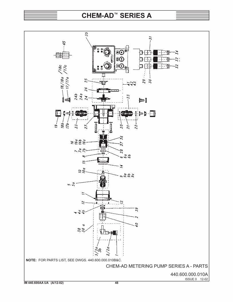
CHEM-AD METERING PUMP SERIES A - PARTS
440.600.000.010AISSUE 0 12-02
NOTE: FOR PARTS LIST, SEE DWGS. 440.600.000.010B&C.
49
CHEM-AD� SERIES A
IM 440.600AA UA (A/12-02)
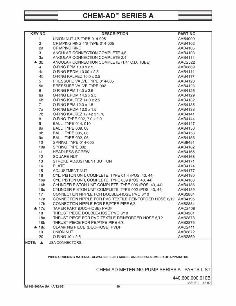
.ONYEK NOITPIRCSED .ONTRAP1 500-410EPYT6/4TUNNOINU 9904BAA2 500-410EPYT6/4GNIRGNIPMIRC 2014BAAa2 GNIRGNIPMIRC 5014BAA3 6/4ETELPMOCNOITCENNOCRALUGNA 8014BAAa3 4/2ETELPMOCNOITCENNOCRALUGNA 1114BAA
� b3 )EBUT.D.O"4/1(ETELPMOCNOITCENNOCRALUGNA 2252CAA4 5.2x0.01MPFGNIR-O 9682BAAa4 5.2x00.01MDPEGNIR-O 4114BAAb4 5.2x0.01ZERLAKGNIR-O 7114BAA
5 500-410EPYTEVLAVERUSSERP 0214BAAa5 200EPYTEVLAVERUSSERP 3214BAA6 5.2x0.41MPFGNIR-O 6214BAAa6 5.2x5.41MDPEGNIR-O 9214BAAb6 5.2x0.41ZERLAKGNIR-O 2314BAA7 5.1x0.21MPFGNIR-O 5314BAAa7 5.1x0.21MDPEGNIR-O 8314BAAb7 87.1x24.21ZERLAKGNIR-O 1414BAA8 0.2x0.7,200EPYT,GNIR-O 4414BAA9 010,410EPYT,LLAB 7414BAAa9 80.900EPYT,LLAB 0514BAAb9 80,500EPYT,LLAB 3514BAAc9 60,200EPYT,LLAB 6514BAA01 500-410EPYT,GNIRPS 1849BAAa01 200EPYT,GNIRPS 2614BAA
11 WERCSSSELDAEH 5614BAA21 TUNERAUQS 8614BAA31 NOTTUBTNEMTSUJDAEKORTS 1714BAA41 ETALP 4714BAA51 TUNTNEMTSUJDA 7714BAA61 )44,34.SOP(410EPYT,ETELPMOC,TINUNOTSIP.LYC 0814BAAa61 )44,34.SOP(900EPYT,ETELPMOC,TINUNOTSIP.LYC 3814BAAb61 )44,34.SOP(500EPYT,ETELPMOCTINUNOTSIPREDNILYC 6814BAAc61 )44,34.SOP(200EPYT,ETELPMOCTINUNOTSIPREDNILYC 9814BAA71 01/6CVPESOH-ELBUODROFELPPINNOITCENNOC 4882BAAa71 21/6ESOHDECROFNIERELITXETCVPROFELPPINNOITCENNOC 5914BAAb71 8/6EPIPEFTP/EPROFELPPINNOITCENNOC 4882BAA
� c71 FDVP)ESOH-OUD(TRAPREPAT 8042CAA81 01/6CVPESOH-ELBUODECEIPTSURHT 1024BAAa81 21/6ESOHDECROFNIERELITXET-CVPROFECEIPTSURHT 8782BAAb81 8/6EPIPEFTP/EPROFECEIPTSURHT 5782BAA
� c81 FDVP)ESOH-OUD(ECEIPGNIPMALC 1142CAA91 TUNNOINU 2782BAA02 5.2x01GNIR-O 9682BAA
CHEM-AD METERING PUMP SERIES A - PARTS LIST
440.600.000.010BISSUE 0 12-02
NOTE: ! USA CONNECTORS.
WHEN ORDERING MATERIAL ALWAYS SPECIFY MODEL AND SERIAL NUMBER OF APPARATUS
50IM 440.600AA UA (A/12-02)
CHEM-AD� SERIES A
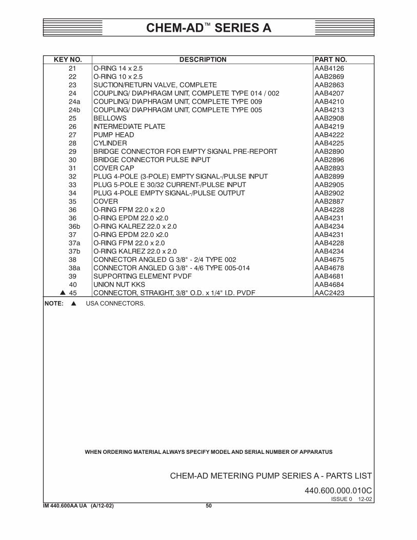
.ONYEK NOITPIRCSED .ONTRAP12 5.2x41GNIR-O 6214BAA22 5.2x01GNIR-O 9682BAA32 ETELPMOC,EVLAVNRUTER/NOITCUS 3682BAA42 200/410EPYTETELPMOC,TINUMGARHPAID/GNILPUOC 7024BAAa42 900EPYTETELPMOC,TINUMGARHPAID/GNILPUOC 0124BAAb42 500EPYTETELPMOC,TINUMGARHPAID/GNILPUOC 3124BAA52 SWOLLEB 8092BAA62 ETALPETAIDEMRETNI 9124BAA72 DAEHPMUP 2224BAA82 REDNILYC 5224BAA92 TROPER-ERPLANGISYTPMEROFROTCENNOCEGDIRB 0982BAA03 TUPNIESLUPROTCENNOCEGDIRB 6982BAA13 PACREVOC 3982BAA23 TUPNIESLUP/-LANGISYTPME)ELOP-3(ELOP-4GULP 9982BAA33 TUPNIESLUP/-TNERRUC23/03EELOP-5GULP 5092BAA43 TUPTUOESLUP/-LANGISYTPMEELOP-4GULP 2092BAA53 REVOC 7882BAA63 0.2x0.22MPFGNIR-O 8224BAA63 0.2x0.22MDPEGNIR-O 1324BAAb63 0.2x0.22ZERLAKGNIR-O 4324BAA73 0.2x0.22MDPEGNIR-O 1324BAAa73 0.2x0.22MPFGNIR-O 8224BAAb73 0.2x0.22ZERLAKGNIR-O 4324BAA83 200EPYT4/2-"8/3GDELGNAROTCENNOC 5764BAAa83 410-500EPYT6/4-"8/3GDELGNAROTCENNOC 8764BAA93 FDVPTNEMELEGNITROPPUS 1864BAA04 SKKTUNNOINU 4864BAA
� 54 FDVP.D.I"4/1x.D.O"8/3,THGIARTS,ROTCENNOC 3242CAA
CHEM-AD METERING PUMP SERIES A - PARTS LIST
440.600.000.010CISSUE 0 12-02
NOTE: ! USA CONNECTORS.
WHEN ORDERING MATERIAL ALWAYS SPECIFY MODEL AND SERIAL NUMBER OF APPARATUS

51
CHEM-AD� SERIES A
IM 440.600AA UA (A/12-02)
SECTION 6 - PREVENTIVE MAINTENANCE KITS AND ACCESSORIES
List of Contents
PARA. NO.
Configuration Code .................................................. 6.1Preventive Maintenance Kit ..................................... 6.2Accessories ............................................................... 6.3

52IM 440.600AA UA (A/12-02)
CHEM-AD� SERIES A
6.1 Configuration Code
To order the correct maintenance kit or spare parts the configuration of thepump must be known. The configuration number is also the ordering codeof that particular pump. Every pump has a data plate attached to it thatspecifies a configured alphanumeric code starting with �CM� and fol-lowed by thirteen (13) numbers or letters.

53
CHEM-AD� SERIES A
IM 440.600AA UA (A/12-02)
6.1.1 USA Version
CM 1 A4 E30 K F G 99 31
Connections, one selection only31 - PVDF adapter 3/8" OD tubing, Duo hose connections, 1/4"OD tubing connections
Valve Sets, one selection only99 - Standard valve, PVDF, no spring load
Ball Material, one selection onlyG - Glass Ball, (Ceramic Ball in the metering discharge)
O-ring MaterialsF - Viton, standardE - EPDM, optionalK - Kalrez, optional
Pump Head Material, one selection onlyK - PVDF
Control ModeE11 - No Electronic Control, standard
On/Off buttonMechanical Stroke Adjustment6 ft cable with USA Standard Plug
E30 - Electronic Control OptionMechanical Stroke AdjustmentStroke Frequency ControlLevel Switch ConnectionAlarm and Stroke Signal Output0/4 - 20 mA or Pulse Input6 ft cable with USA Standard plug.
Series, Capacity and PressureA1 - 0.06 GPH at 60 Hz., 120 PSIA2 - 0.16 GPH at 60 Hz., 120 PSIA3 - 0.29 GPH at 60 Hz., 120 PSIA4 - 0.44 GPH at 60 Hz., 120 PSI
Power Supply1 - 115 VAC, 60 Hz., Single Phase, USA Version only3 - 230 VAC, 50 Hz., Single Phase, EURO Version only
Product Prefix Code

54IM 440.600AA UA (A/12-02)
CHEM-AD� SERIES A
6.1.2 EURO Version
CM 3 A4 M30 K F G 99 33
Connections, one selection only33- PVDF, Connection Set, 6/8, 6/10 (mm ID/mm OD)
Connection Set for Duo Hose
Valve Sets, one selection only99 - Standard valve, PVDF, no spring load
Ball Material, one selection onlyG - Glass Ball, (Ceramic Ball in the metering discharge)
O-ring MaterialsF - Viton, standardE - EPDM, optionalK - Kalrez, optional
Pump Head Material, one selection onlyK - PVDF
Control ModeM11 - No Electronic Control, standard
On/Off buttonMechanical Stroke Adjustment6 ft cable with EURO Plug
M30 - Electronic Control OptionMechanical Stroke AdjustmentStroke Frequency ControlLevel Switch ConnectionAlarm and Stroke Signal Output0/4 - 20 mA or Pulse Input6 ft cable with EURO plug.
Series, Capacity and PressureA1 - 0.2 LPH at 50 Hz., 10 BARA2 - 0.5 LPH at 50 Hz., 10 BARA3 - 0.9 LPH at 50 Hz., 10 BARA4 - 1.4 LPH at 50 Hz., 10 BAR
Power Supply1 - 115 VAC, 60 Hz., Single Phase, for USA Version only3 - 230 VAC, 50 Hz., Single Phase, for EURO Version only
Product Prefix Code

55
CHEM-AD� SERIES A
IM 440.600AA UA (A/12-02)
6.2 Maintenance Kit
For convenient ordering, the Maintenance Kit consists of all the partsnecessary to perform regular required maintenance for the pump. Referto Figure 6.1 for a diagram of the parts that comprise each particular kit.
Figure 6.1 - Maintenance Kit Parts Reference

56IM 440.600AA UA (A/12-02)
CHEM-AD� SERIES A
6.2.1 Head Kit
Order one (1) kit per pump
1.6erugiFeeS-snoitpircseDnoisreVASU
pmuPnoisreVcirteM
pmuP
AseireS,)h/l42.0(HPG60.0roftiKdaeHsnoitcennocsedulcni,llabSSALGdnagnir-ONOTIV
AseireS,)h/l42.0(HPG60.0roftiKdaeHsnoitcennocsedulcni,llabSSALGdnagnir-OMDPE
AseireS,)h/l42.0(HPG60.0roftiKdaeHsnoitcennocsedulcni,llabCIMARECdnagnir-ONOTIV
AseireS,)h/l42.0(HPG60.0roftiKdaeHsnoitcennocsedulcni,llabCIMARECdnagnir-OMDPE
AseireS,)h/l42.0(HPG60.0roftiKdaeHsnoitcennocsedulcni,llabEFTPdnagnir-OZERLAK
3782CAA
6782CAA
9782CAA
2882CAA
4472CAA
6055BAA
4255BAA
6355BAA
8455BAA
8003CAA
AseireS,)h/l6.0(HPG61.0roftiKdaeHsnoitcennocsedulcni,llabSSALGdnagnir-ONOTIV
AseireS,)h/l6.0(HPG61.0roftiKdaeHsnoitcennocsedulcni,llabSSALGdnagnir-OMDPE
AseireS,)h/l6.0(HPG61.0roftiKdaeHsnoitcennocsedulcni,llabCIMARECdnagnir-ONOTIV
AseireS,)h/l6.0(HPG61.0roftiKdaeHsnoitcennocsedulcni,llabCIMARECdnagnir-OMDPE
AseireS,)h/l6.0(HPG61,0roftiKdaeHsnoitcennocsedulcni,llabEFTPdnagnir-OZERLAK
5882CAA
8882CAA
1982CAA
4982CAA
7472CAA
2155BAA
7255BAA
9355BAA
1555BAA
1103CAA

57
CHEM-AD� SERIES A
IM 440.600AA UA (A/12-02)
6.2.1 Head Kit (Cont'd)
1.6erugiFeeS-snoitpircseDnoisreVASU
pmuPnoisreVcirteM
pmuP
AseireS,)h/l80.1(HPG92.0roftiKdaeHsnoitcennocsedulcni,llabSSALGdnagnir-ONOTIV
AseireS,)h/l80.1(HPG92.0roftiKdaeHsnoitcennocsedulcni,llabSSALGdnagnir-OMDPE
AseireS,)h/l80.1(HPG92.0roftiKdaeHsnoitcennocsedulcni,llabCIMARECdnagnir-ONOTIV
AseireS,)h/l80.1(HPG92.0roftiKdaeHsnoitcennocsedulcni,llabCIMARECdnagnir-OMDPE
AseireS,)h/l80.1(HPG92.0roftiKdaeHsnoitcennocsedulcni,llabEFTPdnagnir-OZERLAK
7982CAA
0092CAA
4103CAA
7103CAA
0572CAA
5155BAA
0355BAA
2455BAA
4555BAA
0203CAA
AseireS,)h/l86.1(HPG44.0roftiKdaeHsnoitcennocsedulcni,llabSSALGdnagnir-ONOTIV
AseireS,)h/l86.1(HPG44.0roftiKdaeHsnoitcennocsedulcni,llabSSALGdnagnir-OMDPE
AseireS,)h/l86.1(HPG44.0roftiKdaeHsnoitcennocsedulcni,llabCIMARECdnagnir-ONOTIV
AseireS,)h/l86.1(HPG44.0roftiKdaeHsnoitcennocsedulcni,llabCIMARECdnagnir-OMDPE
AseireS,)h/l86.1(HPG44.0roftiKdaeHsnoitcennocsedulcni,llabEFTPdnagnir-OZERLAK
3203CAA
6203CAA
9203CAA
2303CAA
3572CAA
8155BAA
3355BAA
5455BAA
7555BAA
5303CAA

58IM 440.600AA UA (A/12-02)
CHEM-AD� SERIES A
6.2.2 USA Connection Kit
:rofnoitcennoC snoitpircseDredrOytitnauQ
rebmuNtraP
xDI"8/1htiwegrahcsiDgnireteMgnibutenelyhteylopDO"4/1
ot8/3G,noitcennocralugnAFDVP,gnibutDO"4/1
)1(enO 2252CAA
"8/3xDI"4/1htiwnoitalucric-eRgnibutenelyhteylopDO
ot8/3G,thgiarts,rotcennoCFDVP,gnibutDO"8/3
)2(owT 3242CAA
tiK,esohouDhtiwnoitalucric-eR:fostsisnoc
FDVP,8/3G,tuNnoinUFDVP,eceipgnipmalC
FDVP,traPderepaTro,MDPE,NOTIV,gnir-O
ZERLAK
tiKnoitcennoCesoHouDgnir-ONOTIVhtiw
tiKnoitcennoCesoHouDgnir-OMDPEhtiw
tiKnoitcennoCesoHouDgnir-OZERLAKhtiw
)2(owT
)2(owT
)2(owT
6572CAA
9572CAA
2672CAA
6.2.3 Metric Connection Kit
:rofnoitcennoC snoitpircseDredrOytitnauQ
rebmuNtraP
thgiarts,gniretemroftesnoitcennoCthgiarts,noitalucric-erroftesnoitcennoC
DOmm4xDImm2DOmm6xDImm4
)1(enO)2(owT
8303CAA1403CAA
delgna,gniretemroftesnoitcennoCdelgna,noitalucric-erroftesnoitcennoC
DOmm4xDImm2DOmm6xDImm4
)1(enO)2(owT
4403CAA7403CAA
:fostsisnoctiK,esohouDhtiwnoitalucric-eRFDVP,8/3G,tuNnoinU
FDVP,eceipgnipmalCFDVP,traPderepaT
roMDPE,NOTIV,gnir-OZERLAK
tiKnoitcennoCesoHouDgnir-ONOTIVhtiw
noitcennoCesoHouDgnir-OMDPEhtiwtiK
noitcennoCesoHouDgnir-OZERLAKhtiwtiK
)2(owT
)2(owT
)2(owT
0503CAA
3503CAA
6503CAA

59
CHEM-AD� SERIES A
IM 440.600AA UA (A/12-02)
6.2.4 Valve Kits for Re-circulation Valve
6.2.5 Electronic Board Assembly and Motor
PMUPNOISREV
LORTNOCSNOITPO
CINORTCELEDRAOB
ROTOM EGATLOV
NOISREVASU11E 1715CAA
8315CAA zH06,CAV51103E 4715CAA
NOISREVORUE11M 4025CAA
3515CAA zH05,CAV03203M 7025CAA
1.4erugiFeeS-snoitpircseDnoisreVASU
pmuPnoisreVcirteM
pmuP
sedulcni,AseireS,ylbmessaevlaVnoitalucric-eRetelpmoCsnoitcennoc
gnir-ONOTIVdnaLLABSSALGhtiwgnisuohFDVP
9503CAA 3682BAA
sedulcni,AseireS,ylbmessaevlaVnoitalucric-eRetelpmoCsnoitcennoc
gnir-OMDPEdnaLLABSSALGhtiwgnisuohFDVP
2603CAA 5672CAA
AseireS,ylbmessaevlaVnoitalucric-eRetelpmoCgnir-ONOTIVdnaLLABCIMAREChtiwgnisuohFDVP
5603CAA 8672CAA
sedulcni,AseireS,ylbmessaevlaVnoitalucric-eRetelpmoCsnoitcennoc
gnir-OMDPEdnaLLABCIMAREChtiwgnisuohFDVP
8603CAA 1772CAA
sedulcni,AseireS,ylbmessaevlaVnoitalucric-eRetelpmoCsnoitcennoc
gnir-OZERLAKdnaLLABEFTPhtiwgnisuohFDVP
1703CAA 4772CAA
60IM 440.600AA UA (A/12-02)
CHEM-AD� SERIES A
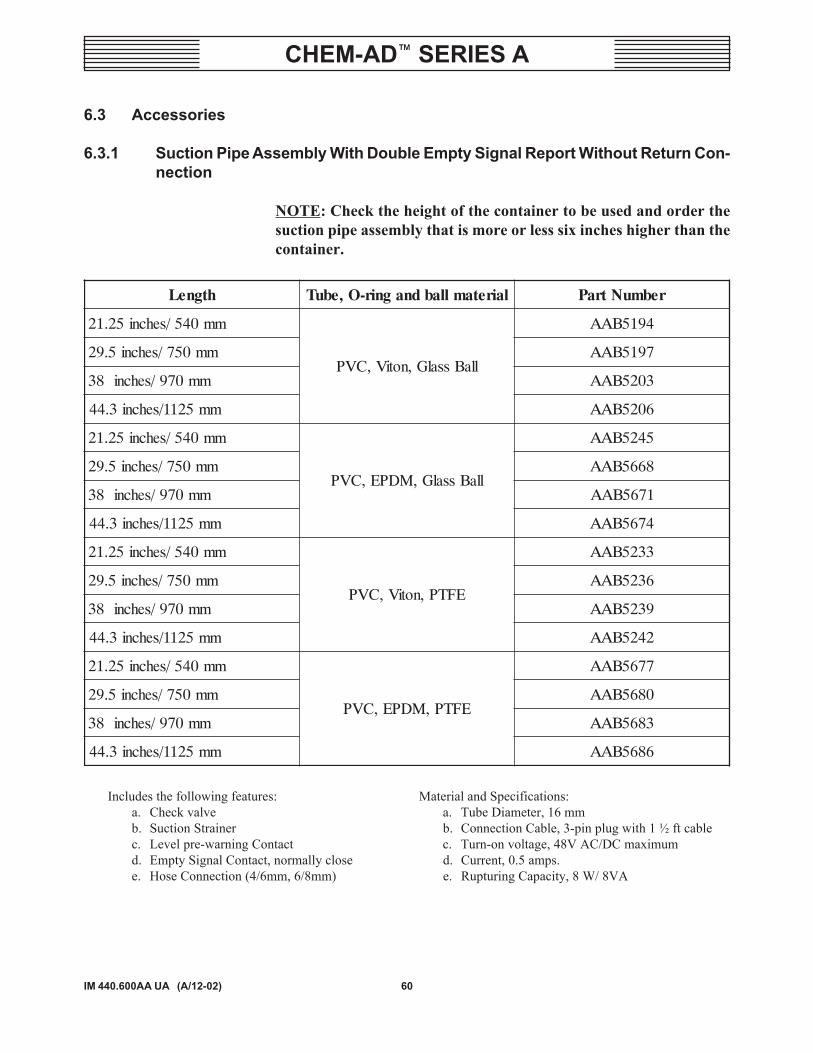
6.3 Accessories
6.3.1 Suction Pipe Assembly With Double Empty Signal Report Without Return Con-nection
NOTE: Check the height of the container to be used and order thesuction pipe assembly that is more or less six inches higher than thecontainer.
Includes the following features: Material and Specifications:a. Check valve a. Tube Diameter, 16 mmb. Suction Strainer b. Connection Cable, 3-pin plug with 1 ½ ft cablec. Level pre-warning Contact c. Turn-on voltage, 48V AC/DC maximumd. Empty Signal Contact, normally close d. Current, 0.5 amps.e. Hose Connection (4/6mm, 6/8mm) e. Rupturing Capacity, 8 W/ 8VA
htgneL lairetamllabdnagnir-O,ebuT rebmuNtraP
mm045/sehcni52.12
llaBssalG,notiV,CVP
4915BAA
mm057/sehcni5.92 7915BAA
mm079/sehcni83 3025BAA
mm5211/sehcni3.44 6025BAA
mm045/sehcni52.12
llaBssalG,MDPE,CVP
5425BAA
mm057/sehcni5.92 8665BAA
mm079/sehcni83 1765BAA
mm5211/sehcni3.44 4765BAA
mm045/sehcni52.12
EFTP,notiV,CVP
3325BAA
mm057/sehcni5.92 6325BAA
mm079/sehcni83 9325BAA
mm5211/sehcni3.44 2425BAA
mm045/sehcni52.12
EFTP,MDPE,CVP
7765BAA
mm057/sehcni5.92 0865BAA
mm079/sehcni83 3865BAA
mm5211/sehcni3.44 6865BAA

61
CHEM-AD� SERIES A
IM 440.600AA UA (A/12-02)
lairetaMdnaeziSgnibuTmumixaM
C02@erusserPrab/isP
rebmuNtraPesehtnodesUsnoitcennoCpmuP
m2xmm01/6,esohoudCVP 8/021 2365BAA cirteMdnaASUsnoitcennoC
enelyhteylop,DI"4/1xDO"8/3 taisp56107 ° F
818486PRnoitcennoCASU
enelyhteylop,DI"8/1xDO"4/1 8/521 744486PR noitcennoCASU
elamTPN"4/1otgnibutDO"4/1enelyporpylop,gnittifthgiarts
54082UnoitcennoCASU
elamTPN"4/1otgnibutDO"4/1enelyporpylop,gnittifwoble
64082UnoitcennoCASU
elamTPN"4/1otgnibutDO"8/3CVP,thgiarts,retpadACVP,wobleeerged09
tuNgnilpuoCretpadaehtroftungnilpuocredrO(
)evobawobledna
33293P53293P43293AXP
noitcennoCASU
elamefTPN"4/1otebut"4/1FDVP
CVP29432U51622U
snoitcennoCASU
mm01/4cirbaf-CVP 42/063 1744819PR
noitcennoCcirteMmm21/6cirbaf-CVP 32/543 7744819PR
mm6/4,enelehteyloP 01/051 5344119PR
mm8/6,enelehteyloP 8/021 1544119PR
6.3.2 Suction and Discharge Lines and Fittings

62IM 440.600AA UA (A/12-02)
CHEM-AD� SERIES A
noitpircseD rebmuNtraP
PP,erawdrahgnitnuomhtiwtekcarBllaW 9787BAA
CVP,tekcarBllaW 6984EJA
sselniatS,tekcarBllaW 8033AAA
lairetaM noitcennoC teppoP sgnir-O rebmuNtraP
dnaCVP,redlohevlaVneercsenelyporpyloP
DO"8/3xDI"4/1 ranyK notiV 44032U
dnaFDVP,redlohevlaVneercsenelyporpyloP
DO"8/3xDI"4/1 ranyK zerlaK 64782U
gnisuoHlairetaM
snoitcennoCmumixaM
wolF&egnaRerusserPstimiLerutarepmeT
&mgarhpaiDgnir-O
traPrebmuN
CVP
TPN"4/1dnatelniteltuo
hpg5.5
isp071ot52021-53 ° F
decaf-EFTgnir-OnolapyH
57752U
ranyKisp071ot52
081-53 ° Fdecaf-EFTgnir-OnotiV
87752U
ranyKisp071ot52
081-53 ° Fdecaf-EFTgnir-OzerlaK
00472U
6.3.3 Wall Mounting Bracket
6.3.4 Foot Valve Strainer
NOTE: Position the foot valve strainer vertically and at the lowestpoint of the container.If agitation is used, use rigid pipe to prevent tubing from becomingentangled with the propeller.Order rigid pipe adapter U22615 (1/4" NPT) PVC or U23492 (1/4"NPT) PVDF.
6.3.5 Back Pressure Valve

63
CHEM-AD� SERIES A
IM 440.600AA UA (A/12-02)
snoitcennoC lairetaM HPGyticapaCwolF rebmuNtraP
gnibutDO"8/3 CVP 5.5 64812U
gnibutDO"8/3 ranyK 5.5 96742U
etaRwolF yticapaC snoitcennoCdnE rebmuNtraP
HPG5.1-0 Lm001 TPNF"2/1 3452CAA
HPG4-0 Lm052 TPNF"2/1 6452CAA
HPG8-0 Lm005 TPNF"4/3 9452CAA
noitpircseD rebmuNtraP
htgnelM5/tf4.61,ylbmessaelbacnoitcennoCgulpnip-4thgiartshtiwtupnilangisytpmeroF
gulpnip-4thgiartshtiwtupniesluproFgulpnip-5thgiartshtiw,03E,tupnitnerrucroesluproF
gulpnip-4thgiartshtiwtuptuolangisekortsrolangisytpmeroF
2116BAA5116BAA8116BAA1216BAA
gnisuoHlairetaM
snoitcennoCmumixaM
wolF&egnaRerusserPstimiLerutarepmeT
&mgarhpaiDgnir-O
traPrebmuN
CVP
TPN"4/1dnatelniteltuo
hpg5.5
isp071ot52021-53 ° F
decaf-EFTgnir-OnolapyH
67752U
ranyKisp071ot52
081-53 ° Fdecaf-EFTgnir-OnotiV
77752U
ranyKisp071ot52
081-53 ° Fdecaf-EFTgnir-OzerlaK
10472U
6.3.6 Pressure Relief Valve
6.3.7 Main Connections
6.3.8 Calibration Column
6.3.9 Electrical Cable Assemblies


