

Article citation info:
BALICKI, W., GŁOWACKI, P. Causes of the powerplants failures installed on Polish civil aviation aircraft. Combustion Engines. 2017,
168(1), 110-121. DOI: 10.19206/CE-2017-117
110 COMBUSTION ENGINES, 2017, 168(1)
Włodzimierz BALICKI CE-2017-117 Paweł GŁOWACKI
Causes of the powerplants failures installed on Polish civil aviation aircraft
Currently in Poland about 2,500 different engine types are installed on the aircraft. In the years 2008-2016 powerplants failures
caused nearly 600 aviation events. Aborted flight or emergency landing, especially in the case of aircraft powered by a single piston
engine occurred. The objective of the article was to determine the failure causes and assessment of their impact on the flight safety.
Engine faults were assigned to particular types of powerplants, for example turboshaft, piston, etc. Causes of the failures were examined,
assigning ATA chapter to each of them. Also human factor was taken into account. According to the ICAO methodology, aviation safety
engine systems essential for flight safety and theirs impact on the safety risk was determined. The results of the analyzes presented in this
article are useful for managing the national aviation safety and supervising SMS in aviation organizations. The article shows that
preventive measures to raise the level of aviation safety should be taken. This is the first comprehensive analysis of the powerplants
failure causes and an evaluation of their influence on the level of aviation safety in Poland.
Key words: powerplant, aircraft engine failure, safety risk
1. Introduction The hitherto operational experience indicate that to the
greatest extent powerplant determines airplanes and heli-
copters safety of flying. Still significant number of aircraft
engines exploitation is a subject of the guaranteed by manu-
facturers service life (so-called “hard time”) [8, 9]. Such
a time is usually determined by the manufacturers carrying
out test-bed endurance programs where the engine is run
day and night, cycling through a specified and purposely
over-punishing schedule of so many hours at full power, so
many at idle, so many at cruise. During the manufacturer’s
tests the engine is run on the test bed in a manner which
is purposely more severe than ordinary operator will use.
Often engines are tested in the flying beds as well as high
altitude test-cells. During tests engine durability, especially
resistance on uncontained failure of the fan, compressor and
turbine cases are checked. Also resistance of the fan blades
against bird strike is examined.
The hard time exploitation method requires technical in-
spections and engine overhaul conducting after its work for
a certain period of time (regardless of the actual technical
condition of the engine). After a guaranteed by manufactur-
er life the engine is subject of a cassation. The advantage
of this method of operation is the possibility of a relatively
simple overhaul and maintenance tasks planning, spare
parts purchasing and new engines acquisition scheduling.
This system, however, is expensive, because often unneces-
sary maintenance tasks have to be carried out, reduces air-
craft operational readiness, requires removals of a servicea-
ble engine parts (risk of damage during these works), in
brief, increases engine direct maintenance cost.
It was noted that the degree of engine wear depends not
only on the number of its working hours, but also on variety
of difficult to evaluate factors like environmental conditions
(eg. dust, salt, humidity), and aircraft flight profile. Also
level of training and individual pilot psychophysical charac-
teristics are engine condition influencers. An attempt to
take into account the influence factors related to engine
operating conditions was the use of appropriate statistical
tools.
The development of a safe for aircraft application meas-
urement and registration technologies, enabled introduction
of the on-condition exploitation method applied for air-
frames, powerplants and specific aircraft parts. The possi-
bility of obtaining reliable records of the registered parame-
ters resulted, in turn, in the development of data interpreta-
tion methods. For the equipment reliability evaluation
mathematical statistic methods in a wider range were ap-
plied [5, 7, 11]. The reliability function allows a determina-
tion of the system continued operation probability. The
quality of the assessment depends on the obtained data
credibility, samples volume, that is, from the experience
gained during operation of a specific equipment type.
In order to present equipment reliability various indica-
tors are used, which include inter alia time between failure,
time between overhaul or factor describing the number of
its failures per 1000 operating hours [5, 6, 12].
The aircraft engines exploitation practice is to maintain
the required level of the flight safety. For this purpose, in
addition to the assessment of the engine’s technical condi-
tion, identification of its installations significantly affect the
flying safety is carried out. The risk associated with the
frequency of their faults is determined, which is important
one of the elements of aviation safety management system
(SMS).
The identification of aircraft and engines systems was
simplified by the introduction in 1956 standard numbering
system ATA 100 developed by Air Transport Association
(ATA) [4]. This rely on aircraft and engines systems de-
scription by giving them a two-digit number, eg. Chapter 73
– fuel supply and flow control, chapter 74 – ignition, chap-
ter 80 – starting etc. This system has expanded in 1999 by
adding two more digits to indicate each group, defining the
specific subsystems, eg. in the chapter 71 – powerplant
(general) separated: 7110 – cowling, 7120 – mounts, 7150 –
electrical harness etc. During the encoding of events caused
by powerplant, recorded in the data base ECCAIRS
as SCF-PP, the authors used the numbering system identical
for large aircraft, small and helicopters.

Causes of the powerplants failures installed on Polish civil aviation aircraft
COMBUSTION ENGINES, 2017, 168(1) 111
2. Research methodology In order to analyse various types of the powerplants
influence on flight safety, data contained in the ECCAIRS
were reviewed. This database is conducted by SCAAI and
ULC. Contains aviation event reports sent by the organiza-
tions involved in air operations. It is very extensive – con-
tains over 7000 events in air traffic reported between 2008
and 2016. Reported aviation incidents are coded according
to ICAO aviation occurrence categories [1, 2].
Events caused by powerplants coded as SCF-PP were
divided depending on engine type (piston, turboprop, tur-
boshaft and turbine). As the number of Polish registered
aircraft was changing between 2008 and 2016, factor in
order to objectify the data analysis was introduced (equa-
tion 1).
TYPE
TYPETYPE1000
LSP
LZ1000K
⋅= (1)
where: LZTYPE – number of aviation events caused by tur-
boshaft, turboprop, turbine and piston engines in certain
year, LSPTYPE – number of registered aircraft powered by
specified above type of engine in certain year.
Proper safety management lies not only in an
identification of essential safety parameters and prediction
of their level, but also requires an estimation of safety risk
connected with selected safety indicators.
In order to assess safety risk, it is necessary to estimate
the probability that the consequences of hazard will come to
effect during aircraft operations. In literature five point
probability table is frequently used [13]. The Tab. 1
includes five categories, which describe the probability
related to an unsafe event.
Table 1. Safety risk probability [13]
Likelihood Meaning Value
Frequent Likely to occur many times
(has occurred frequently) 5
Occasional Likely to occur sometimes
(has occurred inferequently) 4
Remote Unlikely to occur, but possible
(has occurred rarely) 3
Improbable Very unlikely to occur
(not known to have occurred) 2
Extremely
Improbable
Almost inconceivable that the event will
occured 1
The next step is a safety risk severity assessment, which
is a potential harm that might occur as a consequence of the
identified hazard. Tab. 2 from [13] has been utilized in
order to evaluate safety risk as a consequence of a potential
event caused by any powerplant system.
Based on the two tables above, safety risk assessment
could be performed. Usually it is performed utilizing Tab.3
Safety risk assessment matrix, which is a combination of
severity/probability
Events caused by particular type of powerplant system
were assigned by authors and shown in the safety risk
assessment tables (Tab. 5, Tab. 10, Tab. 13, Tab.16), which
are presented in the chapters disscusing each engine type.
Table 2. Safety risk severity [13]
Severity Meaning Value
Catastrophic Equipment destroyed
Multiple deaths A
Hazardous A large reduction in safety margins,
physical distress or workload such that
the operators cannot be relied upon to
perform their tasks accurately or
completely
Serious injury
Major equipment damage
B
Major A significant reduction in safety
margins, a reduction in the ability of the
operators to cope with adverse
operating conditions as a result of an
increase in workload, or as a result of
conditions impairing their efficiency
Serious incident
Injury to persons
C
Minor Nuisance
Use of emergency procedures
Operating limitations
Minor incident
D
Negligible Little consequences E
Table 3. Safety risk assessment matrix [13]
Risk
probability
Risk severity
Cat
astr
ophic
A
Haz
ard
ou
s
B
Maj
or
C
Min
or
D
Neg
lig
ible
E
Frequent 5 5A 5B 5C 5D 5E
Occasional 4 4A 4B 4C 4D 4E
Remote 3 3A 3B 3C 3D 3E
Improbable 2 2A 2B 2C 2D 2E
Extremely
improbable 1 1A 1B 1C 1D 1E
There was 557 reported events between 2008 and 2016
caused by all engine types installed on Polish registered
aircraft.
Figure 1 shows an annual number of reported aviation
events caused by powerplant types considered in this arti-
cle.
Fig. 1. Number of reported aviation events caused by powerplants installed
on Polish registered aircraft
Figure 2 shows changes of the coefficient K1000
for aviation events occurred within 2008-2016, for all pow-
erplant types. The below presented figures are showing
increased trend of the reported aviation occurences per
1000 registered aircraft for last two years. Such a situation

Causes of the powerplants failures installed on Polish civil aviation aircraft
112 COMBUSTION ENGINES, 2017, 168(1)
is different considering various engine types. Next four
chapters contains detailed information of aviation events
have occurred for each of the powerplant type since 2008.
Fig. 2. Changes of the coefficient K1000 for SCF-PP aviation occurrence
categories
3. Aviation piston engines Piston engines will be a suitable and popular engine
choice among personal airplane owners for many years.
From a manufacturing and engineering perspective, the
reciprocating engines found in piston aircraft are far less
complex than turboprops. Piston aircraft are generally
smaller aircraft, seating no more than six passengers, and
are well suited for relatively short missions of 500 kilome-
ters or less. There are many piston engine models being
currently in operation in Poland. All of them are installed
on aircraft which are operated in general aviation. Tab. 4
contains information about numbers of each installed en-
gine model.
Table 4. Model and number of the piston engines
Engine model Number of installed engines
Austro Engine 5
Bombardier Rotax 101
Continental 208
de Havilland Gipsy Major 3
Franklin 23
Jabiru 2
Limbach 4
LOM 46
Lycoming 492
PZL Kalisz ASZ62 120
PZL Kalisz AI14 94
PZL Kalisz M11 7
PZL Kalisz WN3 3
Rolls Royce 20
Rotor Way RI 4
Simonini Victor 1
Subaru EA 4
Thielert TAE125-01 Centurion 1.7 7
Titan CC340 4
Vedeneyev M14 P 35
Verner 1400 1
Volkswagen 1600 1
Walter Mikron III 3
WSK PZL Rzeszów PZL3 SR 1
Total 1189
Figure 3 shows view of the contemporary utilized typi-
cal aviation piston engine with description of its main parts
[3].
Fig. 3. Four cylinders, horizontally opposed, air cooled aviation piston
engine
3.1. General information
There was totally 207 aviation events caused by piston
engines in 2008-2016. Due to the fact that almost 95% of
the piston engines powered aircraft are single engine
airplane each failure is not the only a threat to the flying
crew safety, but most importantly for individuals on the
ground. Figure 4 shows an annual number of reported aviation
events caused by piston engines. Figure 5 shows changes
of the coefficient K1000pist.between 2008-2016.
Fig. 4. Number of events caused by piston engines installed on Polish
registered aircraft between 2008-2016
Fig. 5. Changes of the coefficient K1000pist.
It has to be pointed out that for last two years sudden,
significant increase in number of events caused by this

Causes of the powerplants failures installed on Polish civil aviation aircraft
COMBUSTION ENGINES, 2017, 168(1) 113
engine type is observed. From 17 in 2014 to 43 in 2016 –
more than twice.
Figure 6 gives (in percent) information during which
aircraft maneuver and how often reported event caused by
piston engine took place in 2008-2016. It is unacceptable
that the vast amount of the powerplant reported failures
occurred during aircraft movement. Only 15% of them were
detected during routine maintenance tasks.
Fig. 6. Flight phases share when piston engine malfunction took place
Figure 7 shows reported system defects frequency in
percent assigned to the certain ATA chapter for the piston
engines in the 2008-2016.
Fig. 7. Share of each powerplant system events coded by ATA 100 chapter
between 2008 and 2016
The above Fig. 7 shows “share” of the certain ATA
chapter in percent in the total volume of the piston engines
reported events. It was assumed that the most frequently
occurred event – ATA chapter 72 has occurrence
probability level equel 5. Next 79, 74 and 73 level 4, 61
level 3, 76 and 80 level 2 and the remaining 62, 71, 75, 77,
78, 81 and 83 level 1. According to the methodology de-
scribed in the introduction (Tab. 1, Tab. 2 and Tab. 3) to
each from the above ATA chapters safety risk severity was
assigned, based on events consequences described in the
ECCAIRS reports. Then safety risk assessment matrix was
developed for piston engines operated in Poland. Results of
the analysis are presented in the Tab. 5.
Every item presented in the red field requires immediate
actions, which have to be taken on the country level in
order to mitigate safety risk connected with the highlted in
red engine systems coded in ATA 72, 74 and 79 chapters.
Engine systems marked in yellow are acceptable based on
risk (moderate risk) mitigation. However, a schedule for
performance of safety assessment has to be prepared in
order to find ways to bring down safety risk to low. In this
way aviation authority can develop or order program
implementation of safety risk mitigation, in our case on
Country level. Below are discussed in details “red” ATA
chapters.
Table 5. Safety risk assessment matrix for piston engine systems
ATA chapter Index
No. Contents
61 Propellers/propulsors 3C
62 Main rotor(s) 1D
71 Powerplant general 1C
72 Engine-reciprocating 5B
73 Engine-fuel and control 4C
74 Ignition 4B
75 Bleed air 1E
76 Engine controls 2C
77 Engine indicating 1C
78 Exhaust 1E
79 Oil 4B
80 Starting 2D
81 Turbines 1E
83 Accessory gear boxes 1D
3.2. ATA chapter 72
There were 97 reported aviation events in the ATA 72
chapter between 2008-2016. Figure 8 shows an annual
number of reported events as a result of piston engine fail-
ures coded in that chapter.
Figure 9 gives (in percent) information during which
aircraft maneuver and how often failure of the piston engine
in the ATA 72 chapter took place between 2008-2016.
Fig. 8. Number of events caused by piston engines installed on Polish
registered aircraft in the ATA 72 chapter between 2008-2016
Fig. 9. Flight phases share when powerplant malfunction ATA chapter 72
took place

Causes of the powerplants failures installed on Polish civil aviation aircraft
114 COMBUSTION ENGINES, 2017, 168(1)
Majority failures concern ATA sub charters 72-20-00
power section and 72-30-00 cylinder section. As a result
of the engine failure serious events took place. Table 6
shows in numbers result of the piston engines malfunction,
symptoms observed and precursors of the powerplant de-
fect, where it was confirmed.
Almost 50% out of the total (207) occurrences caused
by powerplants can be assigned to the engine itself (see Fig.
7). Most of the events are connected with powertrain and
cylinder systems. The events were caused by cracked ex-
haust valves. Also carbon deposit was observed on them.
Other occurrences were caused by different failures of the
cylinders. It can be presumed that those damages were
mainly due to engines overheating that resulted from an
improper exploitation.
3.3. ATA chapter 74
During 2008-2016 there was 19 events caused by igni-
tion system. All of them in the two ATA sub chapters
74-10-00 electrical power supply and 74-20-00 distribution.
First includes magnetos, second spark plugs.
Figure 10 gives information during which aircraft ma-
neuver a failure in the ATA 74 chapter took place within
2008-2016. The Tab. 7 shows in numbers result of the en-
gine ignition system malfunctions, symptoms observed and
precursors of the powerplant defects, where it was con-
firmed.
Spark plugs during post event checks were found with
carbon deposit, few wrongly fitted, which again is an evi-
dence of careless maintenance or failure to meet engine
exploitation procedures. More than 70% of ignition system
malfunctions jeopardized flight safety as 13 aborted flights
or emergency landings occurred.
Fig. 10. Flight phases share when powerplant malfunction in the ATA 74
chapter took place
3.4. ATA chapter 79
Between 2008-2016 there was 23 events caused by en-
gine oil system. Figure 11 gives information during which
aircraft maneuver a failure coded in the ATA 79 chapter
took place within 2008-2016.
The Tab. 8 shows in numbers result of the engine oil
system malfunctions, symptoms observed and precursors of
the powerplant defects, where it was confirmed.
Improperly installed or connected oil pipes causing
leaks are the main, but not the only reason, for the reported
events connected with the engine oil system. Most of them
occurred due to maintenance imperfections. Oil system
faults had a significant impact on flight safety. It needs
to be mentioned that in 23 cases, in the years 2008-2016
out of the oil system malfunctions, 19 of them resulted in
aborted flights or emergency landings.
Table 6. Confirmed roots of the piston engines failures coded in the ATA 72 chapter which caused aviation event
No Mulfunction result No Symptom No Confirmed precursor
14 Emergency landing 27 Loss of power 4 Exhaust valve
51 Aborted flight 24 Unstable engine work 5 Cylinder
3 Aborted takeoff 2 Engine overheating 5 Crancase
2 Ground roll stopped 11 In flight shut down 4 Crankshaft
1 Engine vibration 1 Camshaft
2 Connecting rod
Table 7. Confirmed roots of the piston engines failures coded in the ATA 74 chapter which caused aviation event
No Mulfunction result No Symptom No Confirmed precursor
3 Emergency landing 8 Unstable engine work 10 Spark plug
10 Aborted flight 4 Loss of power 5 Magneto
2 Engine vibration 1 Electrical wire
Table 8. Confirmed roots of the piston engines failures coded in the ATA 79 chapter which caused aviation event
No Mulfunction result No Symptom No Confirmed precursor
15 Aborted flight 3 Loss of power 6 Improper maintenance
4 Emergency landing 4 Oil pressure low 6 Metal chips in the oil filter or on
detector
1 Ground roll stopped 3 Oil temperature high
1 Aircraft elements damage 2 Engine vibration
1 Oil pressure high
3 Oil leak
1 Not extended nose gear
1 Oil chip indication

Causes of the powerplants failures installed on Polish civil aviation aircraft
COMBUSTION ENGINES, 2017, 168(1) 115
Fig. 11. Flight phases share when powerplant malfunction in the ATA 79
chapter took place
The above descriptions presented leading to the conclu-
sion that piston engines require changes in the current ex-
ploitation system in order to improve flight safety.
In addition to the existing maintenance and operational
requirements already included in the manufacturers’ manu-
als such a system should introduce new tasks like, for ex-
ample, engine vibration or flight parameters monitoring. It
seems that also more insightful supervision of the mainte-
nance tasks execution as well as way of flying is required.
This will not have only a positive economic impact for
general aviation operators, but also intangible, like im-
provement of the flight safety, technical culture and sense
of responsibility of aviation technical staff and pilots.
4. Turboprop engines Turboprop engines are source of power for aircraft op-
erated in general and commercial aviation. Turboprop air-
craft are generally most efficient at altitudes of 6000 to
9000 meters and at average speeds of 450 km/h to 600
km/h. Turboprops tend to be larger than piston aircraft with
greater passenger capacity – and more fuel on-board – and
are more likely to be found flying distances of up to 2000
km. It seems that turboprops will be used widely for a long
time, both short and medium distances. Table 9 presents
number of installed turboprop engine models on Polish
registered aircraft.
Today's turboprop engines are characterized by a huge
power range (300-11000 kW) and a variety of design
forms. These are now mostly single-rotor with axial or axial
compressors with a radial stage, and a large share (among
small and medium power engines) of separate power tur-
bines.
Table 9. Model and number of the turboprop engines
Engine model Number of installed
engines
PRATT AND WHITNEY PT6A FAMILY 53
PRATT AND WHITNEY PW 150 20
PRATT AND WHITNEY PW 124 10
GENERAL ELECTRIC CT7 5A2 28
HONEYWELL TPE331 3
IVCHENKO AI24 VT 4
LOM M601 E 4
Total 122
Figure 12 shows scheme of the contemporary utilized
popular Pratt &Whitney PT6 turboprop engine with de-
scription of its main parts, covering the power range be-
tween 430 and 680 shaft kilowatts [8, 9].
Fig. 12. Design scheme of PT6 turboprop engine: 1 – air inlet, 2 – com-
pressor, 3 – combustor chamber, 4 – compressor powered turbine, 4’ –
power turbine 5 – exhaust, 6 – reduction gearbox
4.1. General information
There were 101 aviation events caused by turboprop
engine malfunction. It has to be emphasized that in Poland
almost 95% of turbo-propops are twin engines aircraft, so
results of a powerplant failure are not so dangerous like for
single engine aircraft.
Figure 13 shows an annual number of reported aviation
events caused by turboprop engines. Figure 14 shows
changes of the coefficient K1000tprop during 2008-2016.
Fig. 13. Number of events caused by turboprop engines installed on Polish
registered aircraft between 2008-2016
Fig. 14. Changes of the coefficient K1000tprop
Above pictures are showing sudden decrease in number
of events as well as coefficient K1000tprop from 2012 without
turboprop aircraft fleet size changes. Reason for such level
of safety increase is one of the operators aircraft fleet a

Causes of the powerplants failures installed on Polish civil aviation aircraft
116 COMBUSTION ENGINES, 2017, 168(1)
change to another turboprop aircraft type powered by dif-
ferent engine model.
Figure 15 shows reported system defects frequency in
percent assigned to the certain ATA chapter for the turbo-
prop engines in the years 2008-2016. Figure 16 gives (in
percent) information during which aircraft maneuver and
how often reported event caused by turboprop engine took
place within 2008-2016.
Fig. 15. Share of each powerplant system events coded in the ATA 100
chapter between 2008 and 2016
Fig. 16. Flight phases share when powerplant caused event took place
Figure 15 shows in percent “share” of the certain ATA
chapter in the total volume of the turboprop engines
reported events. It was assumed that the most frequently
occurred event – ATA chapter 72 has occurrence
probability level equel 5. Next, 77 and 79 level 4, 61, 73, 76
level 3, 80 level 2 and the remaining 71, 74, 75, 78, level 1.
According to the methodology described in the Introduction
(Tab. 1, Tab. 2 and Tab. 3) to each from the above ATA
chapters safety risk severity was assigned, based on events
consequences described in the ECCAIRS reports.
Then safety risk assessment matrix was developed for
turboprop engines operated in Poland. Results of the
analysis are presented in the Tab. 10.
Table 10. Safety risk assessment matrix for turboprop engine systems
ATA chapter Index
No. Contents
61 Propellers/propulsors 3D
71 Powerplant general 1E
72 Engine 5D
73 Engine-fuel and control 3D
74 Ignition 1E
75 Bleed air 1E
76 Engine controls 3D
77 Engine indicating 4D
78 Exhaust 1E
79 Oil 4C
80 Starting 2E
Similarly like for piston engines, turboprops systems
marked in yellow are acceptable based on risk (moderate
risk) mitigation. However, a schedule for performance of
safety assessment has to be prepared in order to find ways
to bring down safety risk to low. Especially when so many
engine systems fall in moderate risk level. The Tab. 11
shows in numbers result of the turboprops system malfunc-
tions, symptoms observed and precursors of the powerplant
defects, where it was confirmed.
Turboprops failures, which caused aviation events were
mainly due to medium level of engine parts reliability and
durability. There were only seven confirmed maintenance
faults.
5. Turboshaft engines There are 135 helicopters powered by turboshaft en-
gines registered in Poland. Fourteen of them are in MTOM
> 5700 kg class. Most of them is powered by engines mod-
els like: Allison 250C20, different kinds of P&W 206,
Turbomeca Arrius 2F and Arriel 2B1. Also manufactured in
Poland PZL-10W and GTD-350 are being in exploitation.
Mainly twin engine helicopters are utilized. Tab. 12 pre-
sents number of installed turboprop engine models on
Polish registered helicopters.
With the constant number of helicopters, the number of
events reported to the ECCAIRS database have increased
since 2008 (Fig. 18), as a consequence also coefficient
K1000tshaft, proportionally has increased (Fig. 19).
Table 11. Confirmed roots of the turboprop engines failures which caused aviation event
No Mulfunction result No Symptom No Confirmed precursor
25 Aborted flight 12 In flight shut down 6 Auto feather unit/governor
19 Aborted takeoff 12 Unstable engine work 4 Starter generator
4 Ground roll stopped 5 Low oil pressure 5 Torque indication
6 Emergency landing 1 High oil pressure 4 EGT indication
2 Engine vibration 7 Wrong seals/tubes installation
6 PCU/HMU/EEC failure
3 Compressor blades damage
1 Turbine blade damage

Causes of the powerplants failures installed on Polish civil aviation aircraft
COMBUSTION ENGINES, 2017, 168(1) 117
Fig. 17. View and cross-section of the PW 206 turboshaft engine: 1 – air
inlet, 2 – combustor chamber, 2 – compressor, 3 – exhaust, 4 – radial com-
pressor and turbine, 6 – reduction gearbox, 7 – shaft [17]
Table 12. Model and number of the turboshaft powerplants
Engine model Helicopter type Number
of helicopters
PW 206 B2 EC-135 25
GTD-350 Mi-2 24
Turbomeca Arriel 2 B1 EC-130 11
Turbomeca Arrius 2F EC-120 11
PZL-10W W-3 7
GE T-700 S -70i 6
Allison 250 C20B Bell-206, Mi-2 Kania,
H-369 5
Allison 250 C20R2 SW-4 5
Turbomeca Arriel 2 D AS-350; EC-130 4
PW 206 B3 EC-135 4
PW 207 D Bell-427; Bell-429 4
R-R 300 Robinson 66 4
Allison 250 C47B Bell-427 4
Fig. 18. Number of events caused by turboshaft engines installed on Polish
registered aircraft between 2008-2016
Fig. 19. Changes of the coefficient K1000tshaft and the trend line
A more accurate analyzes of the events shows that most
of them concerns engine oil system (ATA 79 chapter) and
ATA 72 chapter. This order is preserved both in terms of
number of events and percentage share (see Fig. 20 and 21).
Fig. 20. Number of the turboshaft engine system events coded in ATA 100
chapter between 2008 and 2016
Fig. 21. Share of turboshaft engine system events coded in ATA 100
chapter between 2008 and 2016
The positive thing is that as many as 2/3 of all tur-
boshaft malfunctions were detected during routine mainte-
nance checks and less than 1/5 during flight, which shows
Fig. 22.
Using a method described in Chapter 2 (Tab. 1 and Tab.
2), a safety hazard assessment chart for turboshaft engines
was developed (Tab. 13). It includes engine systems (coded
according to ATA100) failures were mentioned in the inci-
dent reports. The most frequent failures are related to the oil
system (ATA chapter 79), when malfunctions of the ex-
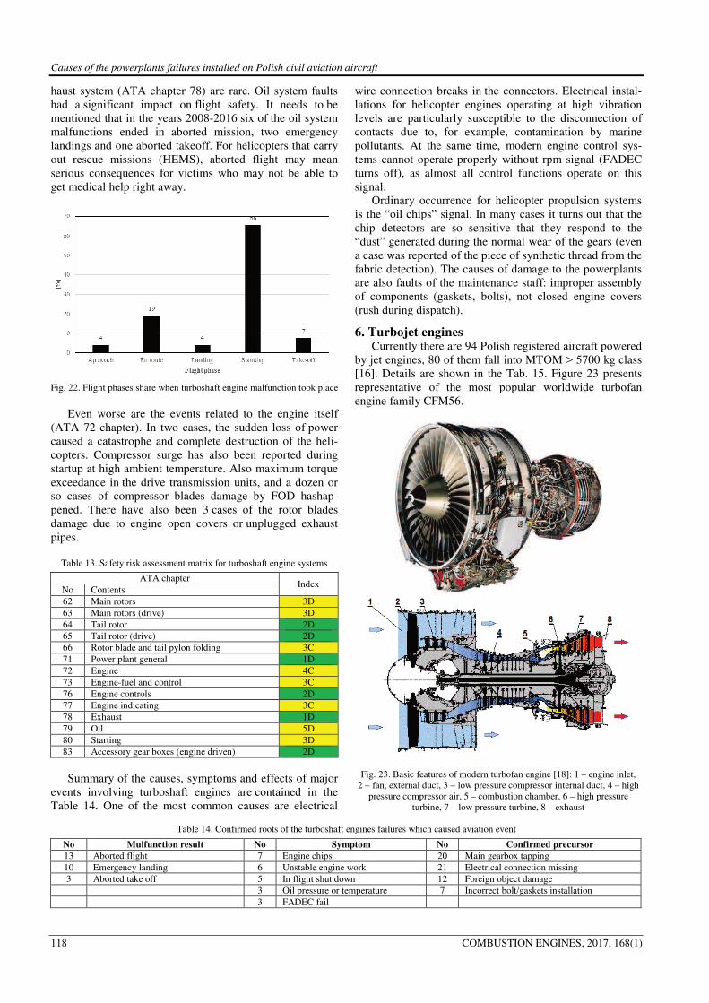
Causes of the powerplants failures installed on Polish civil aviation aircraft
118 COMBUSTION ENGINES, 2017, 168(1)
haust system (ATA chapter 78) are rare. Oil system faults
had a significant impact on flight safety. It needs to be
mentioned that in the years 2008-2016 six of the oil system
malfunctions ended in aborted mission, two emergency
landings and one aborted takeoff. For helicopters that carry
out rescue missions (HEMS), aborted flight may mean
serious consequences for victims who may not be able to
get medical help right away.
Fig. 22. Flight phases share when turboshaft engine malfunction took place
Even worse are the events related to the engine itself
(ATA 72 chapter). In two cases, the sudden loss of power
caused a catastrophe and complete destruction of the heli-
copters. Compressor surge has also been reported during
startup at high ambient temperature. Also maximum torque
exceedance in the drive transmission units, and a dozen or
so cases of compressor blades damage by FOD hashap-
pened. There have also been 3 cases of the rotor blades
damage due to engine open covers or unplugged exhaust
pipes.
Table 13. Safety risk assessment matrix for turboshaft engine systems
ATA chapter Index
No Contents
62 Main rotors 3D
63 Main rotors (drive) 3D
64 Tail rotor 2D
65 Tail rotor (drive) 2D
66 Rotor blade and tail pylon folding 3C
71 Power plant general 1D
72 Engine 4C
73 Engine-fuel and control 3C
76 Engine controls 2D
77 Engine indicating 3C
78 Exhaust 1D
79 Oil 5D
80 Starting 3D
83 Accessory gear boxes (engine driven) 2D
Summary of the causes, symptoms and effects of major
events involving turboshaft engines are contained in the
Table 14. One of the most common causes are electrical
wire connection breaks in the connectors. Electrical instal-
lations for helicopter engines operating at high vibration
levels are particularly susceptible to the disconnection of
contacts due to, for example, contamination by marine
pollutants. At the same time, modern engine control sys-
tems cannot operate properly without rpm signal (FADEC
turns off), as almost all control functions operate on this
signal.
Ordinary occurrence for helicopter propulsion systems
is the “oil chips” signal. In many cases it turns out that the
chip detectors are so sensitive that they respond to the
“dust” generated during the normal wear of the gears (even
a case was reported of the piece of synthetic thread from the
fabric detection). The causes of damage to the powerplants
are also faults of the maintenance staff: improper assembly
of components (gaskets, bolts), not closed engine covers
(rush during dispatch).
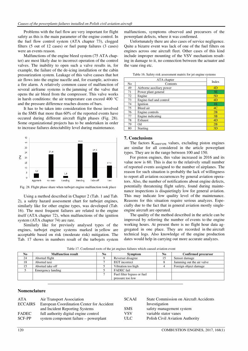
6. Turbojet engines Currently there are 94 Polish registered aircraft powered
by jet engines, 80 of them fall into MTOM > 5700 kg class
[16]. Details are shown in the Tab. 15. Figure 23 presents
representative of the most popular worldwide turbofan
engine family CFM56.
Fig. 23. Basic features of modern turbofan engine [18]: 1 – engine inlet,
2 – fan, external duct, 3 – low pressure compressor internal duct, 4 – high
pressure compressor air, 5 – combustion chamber, 6 – high pressure
turbine, 7 – low pressure turbine, 8 – exhaust
Table 14. Confirmed roots of the turboshaft engines failures which caused aviation event
No Mulfunction result No Symptom No Confirmed precursor
13 Aborted flight 7 Engine chips 20 Main gearbox tapping
10 Emergency landing 6 Unstable engine work 21 Electrical connection missing
3 Aborted take off 5 In flight shut down 12 Foreign object damage
3 Oil pressure or temperature 7 Incorrect bolt/gaskets installation
3 FADEC fail

Causes of the powerplants failures installed on Polish civil aviation aircraft
COMBUSTION ENGINES, 2017, 168(1) 119
The aircraft jet propulsion usually consists of two en-
gines placed under the aircraft wings or at the rear of the
fuselage. Currently on Polish registered aircraft mostly
turbofan engines are installed. They have superior fuel
efficiency over single shaft engines, which are only used in
military applications on aircraft of the 50's.
Table 15. Type and number of the aircraft powered by jet turbine power-
plants
Engine model Aircraft type Number
of aircraft
GE CF-34 Embraer
ERJ 170 and 190 26
CFM-56 serie 3, 5 and 7 Boeing 737 and Airbus
321 24
PW serie 300, 500 and 600
Cessna 510
Embraer 500
Falcon 2000
Learjet 60
8
IAE V2527 Airbus 320 6
Trent 1000 Boeing 787 6
Williams FJ44
Cessna 525
Beech 390
Raytheon 390
6
Allison AE3007 Embraer
EMB 135 and 145 5
Honeywell AS907 Bombardier 100 4
Honeywell TFE731
Gulfstream 150
Learjet 45
Hawker 750
3
Number of reported events as well as factor K1000jet
since 2011 have stabilized (Fig. 24 and 25).
Fig. 24. Number of events caused by turbojet engines installed on Polish
registered aircraft between 2008-2016
Fig. 25. Changes of the coefficient K1000jet and the trend line
Figure 26 presents number of reported events in each
ATA 100 chapter dedicated to powerplant systems. Fig. 27
shows reported system defects frequency in percent as-
signed to the certain ATA chapter for the turbojet engines
in the years 2008-2016. Fig. 28 gives (in percent) infor-
mation during which aircraft maneuver and how often re-
ported event caused by turbojet engine took place between
2008-2016.
Fig. 26. Number of the turbojet engine system events coded by ATA 100
chapter between 2008 and 2016
Fig. 27. Share of turbojet engine system events coded by ATA 100 chapter
between 2008 and 2016
Figure 27 shows “share” of the certain ATA chapter in
percent in the total volume of the turbojet engines reported
events. It was assumed that the most frequently occurred
event concerns engine design parts coded in ATA chapter
72, next are events in the ATA chapters 78, 75 and 73. The
most serious consequences are caused by events related to
the engine itself (chapter ATA 72). In 43 cases, 10 ended
with aborted flight, 4 aborted takeoffs and 1 emergency
landing. The reason was usually the sudden increase in
engine vibration, compressor surge, also exhaust tempera-
ture limit exceedances, and thrust differences between en-
gines causing the aircraft drift during takeoff. Borescope
inspections performed during routine maintenance detected
damage to the fan blades and compressor blades caused by
foreign objects (FOD).
Failures of the exhaust (ATA chapter 78) caused
aborted takeoff (5 out of 14 events). One aborted flight and
one emergency landing took place. During routine
maintenance checks usually thrust reverser sensors
mulfunction were reported.
Causes of the powerplants failures installed on Polish civil aviation aircraft
120 COMBUSTION ENGINES, 2017, 168(1)
Problems with the fuel flow are very important for flight
safety as this is the main parameter of the engine control. In
the fuel flow control system (ATA chapter 73), clogged
filters (5 out of 12 cases) or fuel pump failures (3 cases)
were an events reason.
Malfunctions of the engine bleed system (75 ATA chap-
ter) are most likely due to incorrect operation of the control
valves. The inability to open such a valve results in, for
example, the failure of the de-icing installation or the cabin
pressurization system. Leakage of this valve causes that hot
air flows into the engine nacelle and, for example, activates
a fire alarm. A relatively common cause of malfunction of
several airframe systems is the jamming of the valve that
opens the air bleed from the compressor. This valve works
in harsh conditions: the air temperature can exceed 400 °C
and the pressure difference reaches dozens of bars.
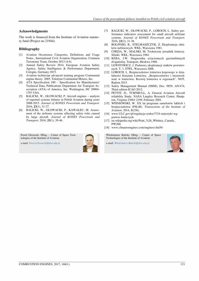
It has to be taken into consideration for those involved
in the SMS that more than 60% of the reported events have
occured during different aircraft flight phases (Fig. 28).
Some organizational projects has to be undertaken in order
to increase failures detectability level during maintenance.
Fig. 28. Flight phase share when turbojet engine malfunction took place
Using a method described in Chapter 2 (Tab. 1 and Tab.
2), a safety hazard assessment chart for turbojet engines,
similarly like for other engine types, was developed (Tab.
16). The most frequent failures are related to the engine
itself (ATA chapter 72), when malfunctions of the ignition
system (ATA chapter 74) are rare.
Similarly like for previusly analysed types of the
engines, turbojet engine systems marked in yellow are
acceptable based on risk (moderate risk) mitigation. The
Tab. 17 shows in numbers result of the turbojets system
malfunctions, symptoms observed and precursors of the
powerplant defects, where it was confirmed.
Unfortunately there are also cases of service negligence.
Quite a bizarre event was lack of one of the fuel filters on
engines across one aircraft fleet. Other cases of this kind
include improper mounting of the VSV mechanism result-
ing in damage to it, no connection between the actuator and
the vane ring etc.
Table 16. Safety risk assessment matrix for jet engine systems
ATA chapter Index
No Contents
49 Airborne auxiliary power 4D
71 Power plant general 3E
72 Engine 5D
73 Engine-fuel and control 4D
74 Ignition 1E
75 Bleed air 4C
76 Engine controls 2B
77 Engine indicating 3B
78 Exhaust 4D
79 Oil 2B
80 Starting 3D
7. Conclusions The factors K1000TYPE values, excluding piston engines
are similar for all considered in the article powerplant
types. They are in the range between 100 and 150.
For piston engines, this value increased in 2016 and its
value now is 60. This is due to the relatively small number
of reported events assigned to the number of airplanes. The
reason for such situation is probably the lack of willingness
to report all aviation occurrences by general aviation opera-
tors. Also, the number of notifications about engine defects,
potentially threatening flight safety, found during mainte-
nance inspections is disquietingly low for general aviation.
This may indicate low quality level of the maintenance.
Reasons for this situation require serious analyzes. Espe-
cially due to the fact that in general aviation mostly single-
engine aircraft are operated.
The quality of the method described in the article can be
improved by referring the number of events to the engine
working hours. At present there is no flight hour data ag-
gregated in one place. They are recorded in the aircraft
technical logs. Also knowledge of the engine production
dates would help in carrying out more accurate analyzes.
Table 17. Confirmed roots of the jet engines failures which caused aviation event
No Mulfunction result No Symptom No Confirmed precursor
24 Aborted flight 9 Reverser disagree 15 Sensor damage
18 Aborted taxi 7 EGT incorrect 8 Jamming out the air valve
15 Aborted take off 5 Vibration too high 4 Foreign object damage
5 Emergency landing 5 FADEC fail
7 Fuel filter bypass or fuel
pressure too low
Nomenclature
ATA Air Transport Association
ECCAIRS European Coordination Center for Accident
and Incident Reporting Systems
FADEC full authority digital engine control
SCF-PP system component failure – powerplant
SCAAI State Commission on Aircraft Accidents
Investigation
SMS safety management system
VSV variable stator vanes
ULC Polish Civil Aviation Authority
Causes of the powerplants failures installed on Polish civil aviation aircraft
COMBUSTION ENGINES, 2017, 168(1) 121
Acknowledgments
The work is financed from the Institute of Aviation statuto-
ry fund (Project no 21944).
Bibliography
[1] Aviation Occurrence Categories, Definitions and Usage
Notes., International Civil Aviation Organization, Common
Taxonomy Team, October 2013 (4.6).
[2] Annual Safety Review 2014, European Aviation Safety
Agency, Safety Intelligence & Performance Department,
Cologne, Germany 2015.
[3] Aviation technician advanced training program Continental
engine theory. 2005, Teledyne Continental Motors, Inc.
[4] ATA Specification 100 – Specification for Manufacturers'
Technical Data, Publications Department Air Transport As-
sociation (ATA) of America, Inc. Washington, DC 20004-
1707 USA.
[5] BALICKI, W., GŁOWACKI, P. Aircraft engines – analysis
of reported systems failures in Polish Aviation during years
2008-2015. Journal of KONES Powertrain and Transport.
2016, 23(1), 31-37.
[6] BALICKI, W., GŁOWACKI, P., KAWALEC, M. Assess-
ment of the airframe systems affecting safety risks caused
by large aircraft. Journal of KONES Powertrain and
Transport. 2016, 23(1), 39-46.
[7] BALICKI, W., GŁOWACKI, P., LOROCH, L. Safety per-
formance indicators assessment for small aircraft airframe
systems. Journal of KONES Powertrain and Transport.
2016, 23(2), 31-38.
[8] BOLIŃSKI, B., STELMASZCZYK, Z. Eksploatacja silni-
ków turbinowych. WKŁ, Warszawa 1981.
[9] CHEDA, W., MALSKI, M. Techniczny poradnik lotniczy.
Silniki. WKŁ, Warszawa 1984.
[10] KEBA, I.W. Diagnostika aviacionnych gazoturbinnych
dvigatieliej. Transport, Moskwa 1980.
[11] LEWITOWICZ, J. Podstawy eksploatacji statków powietrz-
nych. T. 3. ITWL, Warszawa 2006.
[12] LOROCH, L. Bezpieczeństwo lotnictwa krajowego w dzia-
łalności Instytutu Lotnictwa. „Bezpieczeństwo i niezawod-
ność w lotnictwie. Rozwój lotnictwa w regionach”. NOT,
Radom 2015.
[13] Safety Management Manual (SMM), Doc. 9859, AN/474,
Third edition ICAO 2012.
[14] PETTIT, D., TURNBULL, A. General Aviation Aircraft
reliability Study. NASA Langley Research Center, Hamp-
ton, Virginia 23681-2199, February 2001.
[15] WIŚNIOWSKI, W. XX lat programu samolotów lekkich i
bezpieczeństwa (PSLiB). Transactions of the Institute of
Aviation. 2014, 3(236).
[16] www.ULC.gov/pl/regulacja-rynku/3724-statystyki-wg-
portow-lotniczych.
[17] en.wikipedia.org/wiki/Pratt_%26_Whitney_Canada_
PW200.
[18] www.cfmaeroengines.com/engines/cfm56/
Paweł Głowacki, DEng. – Center of Space Tech-
nologies of the Institute of Aviation.
e-mail: [email protected]
Włodzimierz Balicki, DEng. – Center of Space
Technologies of the Institute of Aviation.
e-mail: [email protected]


