

Comparing Setup Errors of CBCT Guidance
System and Optical Positioning System Using
Phantom Experiments
Han Zhou, Jie Zhang, Yun Ge, and Ying Chen School of Electronic Science and Engineering, Nanjing University, China, XianLin Road, JiangSu province, 210046
Email: [email protected]
Kelvin Kian Loong Wong Engineering Computational Biology, School of Computer Science and Software Engineering The University of Western
Australia, 35 Stirling Highway, Crawley, WA 6000.
Email: [email protected]
Abstract—Objective: To compare the clinical positioning
error of patient setup between the cone beams computed
tomography (CBCT) guidance with Optical Positioning
System (OPS), and to evaluate the OPS based on our
proposed approach of patient positioning. Materials and
Methods: A phantom was used. We measured setup errors
in left-to-right (LR) and anterior-to-posterior (AP)
directions by vernier caliper on a graph paper on Varian
Linear accelerator, and then we shifted the couch height to
make the source-to-surface distance (SSD)=100cm and
recorded the height change which was displayed on monitor
screen as the setup error in inferior-to-superior (IS)
direction. Results: Average(Avg) setup errors for the CBCT
guidance system were 0.42mm, 0.50mm,and0.66mm in LR,
IS and AP directions, respectively; the SD of it were 0.24mm,
0.00mm and 0.52mm in LR, IS and AP directions,
respectively. The OPS has an Avg setup error of 0.28mm,
0.40mm and 0.30mm in LR, IS and AP directions and SD of
0.08mm, 0.10mm and 0.07mm in LR, IS and AP directions,
respectively. Conclusion: We demonstrated that OPS shows
a comparable, fast and efficient positioning method
compared to CBCT guidance system, and lives up to the
actual need and will have a wide use in clinical application.
Index Terms—radiotherapy, CBCT guidance system, optical
positioning system.
I. INTRODUCTION
Radiotherapy aims to provide higher dose to the tumor
area than to the tumor area than to the surrounding
normal tissues. It has the advantages of increasing tumor
cure rate, improving the radiate sensibility of the tissue,
and decreasing the damage of normal tissue. However the
normal tissue around the tumor has considerable low
tolerance level to radiation. As a result, in order to
acquire a better tumor control probability (TCP), an
accurate positioning is of paramount importance to
radiation treatment. Besides, positioning accuracy is a
Manuscript received July 20, 2014; revised December 2, 2014.
significant factor for drawing the plan target volume
(PTV)[1]-[3].
With the development of “precise radiotherapy”,
positioning guidance techniques, such as CBCT guidance
system and optical guidance system, have received more
attention and have already widely used in clinical.
The CBCT guidance system is a medical image
acquisition technique. The whole operation process is as
follows. First, the X-ray tube rotates a circle by targeting
the patient as the pivot. At the meantime, the flat panel
detector, located in the tube side, collected the projection
data [4]. When reconstructing those data, we receive the
current position layer of CBCT images. At last, the image
registration between CT and CBCT reveals the set-up
errors, which will be corrected on line. After all these
steps, we achieve the precise placement of the patients [5]
[6].
The Optical Positioning System (OPS), developed by
Nanjing University, achieves precise set-ups through real-
time tracking of the tumor. OPS leads tumor to the center
of the accelerators precisely by tracking the infrared
positioning balls on the patients’ faces or bodies. At the
same time, with the help of three-dimensional
radiotherapy planning system, OPS can maximally kill
the tumor and protect the normal tissues, and then realize
the value of precise radiotherapy [7] [8].
As above, we reported two commonly used methods of
positioning guidance systems. However, due to different
technical principles, the applications of the two methods
in practice clinical practices are also different. Therefore,
the present paper will conduct a comparative study to
explore the positioning error between CBCT guidance
system and OPS guidance system.
II. MATERIALS AND MATHODS
A. Experimental Phantom
A phantom regarded as a virtual patient was positioned
on the treatment couch (Fig. 1(a)). Firstly, we fixed a
metallic sphere (Fig. 1 (b)), which diameter is 1mm,
484
Journal of Medical and Bioengineering Vol. 4, No. 6, December 2015
©2015 Engineering and Technology Publishingdoi: 10.12720/jomb.4.6.484-487
inside the phantom as tumor. Then a graphing paper was
put under the metallic sphere to calculate deviation
position. Secondly, six IR sensitive markers were
attached to the surface of the phantom. The real-time
locations of the six IR sensitive markers, which were
fixed on the phantom, can help OPS monitor the planned
isocenter motion.
(a)
(b)
Figure 1. (a) The phantom that was implemented as a virtual patient. (b) The metallic sphere in the middle layer is the planned isocenter.
B. Optical Positioning System
Superior to other positioning systems in accuracy, OPS
has become the most widely use positioning system in the
field of image guidance [9].
The Optical Positioning System consists of two
components: an optical tracking system (from Northern
Digital Inc.) (as shown Fig. 2) used to detect IR sensitive
markers, and a software used to compute the distance
between the treatment machine isocenter and the planned
isocenter.
Figure 2. The operating principle of optical tracking system
The infrared light released by the infrared ray led
occupied all the detection area. The marked balls,
lobulated in the detection area, reflected light to the two
location sensors. According to the images formed
between the two location sensors, we could calculate the
coordinates of the three dimensional spaces [10].
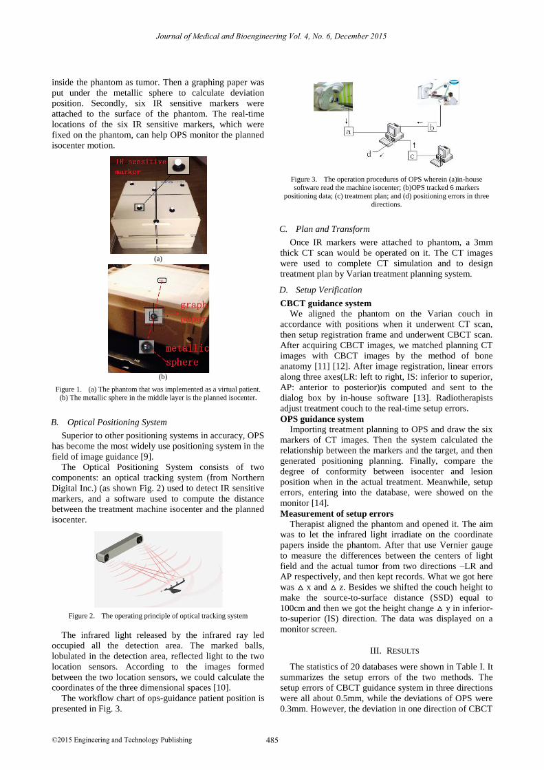
The workflow chart of ops-guidance patient position is
presented in Fig. 3.
Figure 3. The operation procedures of OPS wherein (a)in-house software read the machine isocenter; (b)OPS tracked 6 markers
positioning data; (c) treatment plan; and (d) positioning errors in three directions.
C. Plan and Transform
Once IR markers were attached to phantom, a 3mm
thick CT scan would be operated on it. The CT images
were used to complete CT simulation and to design
treatment plan by Varian treatment planning system.
D. Setup Verification
CBCT guidance system
We aligned the phantom on the Varian couch in
accordance with positions when it underwent CT scan,
then setup registration frame and underwent CBCT scan.
After acquiring CBCT images, we matched planning CT
images with CBCT images by the method of bone
anatomy [11] [12]. After image registration, linear errors
along three axes(LR: left to right, IS: inferior to superior,
AP: anterior to posterior)is computed and sent to the
dialog box by in-house software [13]. Radiotherapists
adjust treatment couch to the real-time setup errors.
OPS guidance system Importing treatment planning to OPS and draw the six
markers of CT images. Then the system calculated the
relationship between the markers and the target, and then
generated positioning planning. Finally, compare the
degree of conformity between isocenter and lesion
position when in the actual treatment. Meanwhile, setup
errors, entering into the database, were showed on the
monitor [14].
Measurement of setup errors Therapist aligned the phantom and opened it. The aim
was to let the infrared light irradiate on the coordinate
papers inside the phantom. After that use Vernier gauge
to measure the differences between the centers of light
field and the actual tumor from two directions –LR and
AP respectively, and then kept records. What we got here
was △ x and △ z. Besides we shifted the couch height to
make the source-to-surface distance (SSD) equal to
100cm and then we got the height change △ y in inferior-
to-superior (IS) direction. The data was displayed on a
monitor screen.
III. RESULTS
The statistics of 20 databases were shown in Table I. It
summarizes the setup errors of the two methods. The
setup errors of CBCT guidance system in three directions
were all about 0.5mm, while the deviations of OPS were
0.3mm. However, the deviation in one direction of CBCT
485
Journal of Medical and Bioengineering Vol. 4, No. 6, December 2015
©2015 Engineering and Technology Publishing

guidance system reached up to 1.5mm. Comparatively,
the deviation of OPS was just about 0.5mm.
The Avg and SD of setup errors were shown in Fig. 4.
TABLE I. SETUP ERRORS AND DIFFERENCES BETWEEN CBCT
GUIDANCE SYSTEM AND OPS.
Setup errors
(mm)
CBCT guidance OPS guidance
Avg
(mm)
SD
(mm)
MAX
(mm)
Avg
(mm)
SD
(mm)
MAX
(mm)
LR/△ x 0.42 0.24 0.80 0.28 0.08 0.40
IS/△ y 0.50 0.00 0.50 0.40 0.10 0.50
AP/△ z 0.66 0.52 1.50 0.30 0.07 0.40
Figure 4. A plot of the Avg and standard deviation (SD) of the setup error
IV. DISCUSSIONS
The accuracy of patient positioning and the reduction
of daily repositioning errors are of great importance to
radiotherapy; as Table I shown, the Avg setup errors of
CBCT and OPS in three directions are less than 1.0mm,
which meets the clinical demand. But the setup errors of
CBCT guidance system are less than that of OPS. Besides
although the standard deviate of setup error of CBCT
guidance system in IS direction is 0 mm, it showed a very
perfect stability. But in LR and AP directions, the errors
were 0.24mm and 0.52mm, which are less than that of
OPS in the same directions. The errors of OPS were 0.08
and 0.07mm. From the results we can see, the setup
stability of OPS is better than CBCT guidance system. It
is because during the process of image registration of
CBCT images and CT images, the matched images are
related to the voxel size of the image [15]. and it also
relies on how the operator of the accelerator justifies the
two images. The generalization of the Avg and standard
deviate of setup error was shown in fig. 4. In general, it
revealed that the number of setup errors of CBCT
guidance system were more than that of OPS’s in most
cases.
According to the above analysis, it can be concluded
that there is a significant correlation between the
positioning error and the application process of CBCT
image registration adjusted by operators [16].
Finally, it should be noted that, according to the
comparison of performance between the two patient-
techniques, the operation process of CBCT is relatively
complex. In order to acquire precisely patient-positioning,
even experience radiotherapist also need to take 5min -10
min to align patients [17], [18]. This process may add
patients’ pain and uncomfortableness. However, OPS can
save many manual operations, and only require thirty
seconds to acquire accurate patient-positioning. The
reason is that OPS operate very simply. Most steps are
finished automatically except drawing the markers which
are completed by hands. As demonstrated above,
radiotherapist can receive localization feedback to locate
target because OPS can monitor the real-time positions of
the planned isocenter and the machine isocenter by
putting them in the same coordinate system [19], [20],
namely the infrared coordinate system. The only thing
that matters here is whether the six IR sensitive markers
can be monitors by OPS. During this process, the
accuracy of the markers’ positions is of no concern, OPS
will be changed as soon as the positions of the markers
are shifted [21].
In summary, OPS improve the accuracy,
reproducibility and survive rate of patient positioning,
and meanwhile reduceenne daily repositioning errors. In
a word, it provides quality assurance for radiotherapy.
V. CONCLUSIONS
We compared OPS and CBCT guidance system by
using phantoms. In the research, this two positioning
methods have achieved higher setup accuracy than
conventional methods. But in terms of accuracy and
stability, OPS are superior to CBCT guidance system.
Compared with CBCT, OPS are more convenient,
efficient, and suitable for clinical practices. Infrared
system improves the shortcomings of CBCT guidance
system such as time-consuming. Therefore, OPS are a top
choice method for patient positioning due to its high
accuracy and efficiency, which may replace CBCT one
day.
ACKNOWLEDGMENT
This work is supported by the National Nature Science
Foundation of China (81371638), Fundamental Research
Funds for the Central Universities (1106021034), Jiangsu
Provincial Nature Science Foundation of China
(BE2012158, BK2011393 and BY2012186).
REFERENCES
[1] Y. Seppenwoolde, et al., “Precise and real-time measurement of
3D tumor motion in lung due to breathing and heartbeat, measured during radiotherapy,” International Journal of Radiation
Oncology Biology Physics, vol. 53, no. 4, pp. 822-834, 2002.
[2] T. R. Mackie, et al., “Image guidance for precise conformal radiotherapy,” International Journal of Radiation Oncology
Biology Physics, vol. 56, no. 1, pp. 89-105, 2003. [3] P. Seiler, et al., “A novel tracking technique for the continuous
precise measurement of tumour positions in conformal
radiotherapy,” Physics in Medicine and Biology, vol. 45, no. 9. pp. N103, 2000.
[4] R. Guijarro-Martinez and G. Swennen, “Cone-beam computerized tomography imaging and analysis of the upper airway: A
systematic review of the literature,” International Journal of Oral
and Maxillofacial Surgery, vol. 40, no. 11, pp. 1227-1237, 2011. [5] L. Xin, et al., A comparative Evaluation of Cone Beam Computed
Tomography (CBCT) and Multi-Slice CT (MSCT), 2010.
486
Journal of Medical and Bioengineering Vol. 4, No. 6, December 2015
©2015 Engineering and Technology Publishing

[6] M. Velec, et al., “Cone-beam CT assessment of interfraction and intrafraction setup error of two head-and-neck cancer
thermoplastic masks,” International Journal of Radiation
Oncology Biology Physics, vol. 76, no. 3, pp. 949-955, 2010. [7] F. Watzinger, et al., “Positioning of dental implants using
computer-aided navigation and an optical tracking system: Case report and presentation of a new method,” Journal of Cranio-
Maxillofacial Surgery, vol. 27, no. 2, pp. 77-81, 1999.
[8] X. Liang, et al., “A comparative evaluation of cone beam computed tomography (CBCT) and multi-slice CT (MSCT). Part
II: On 3D model accuracy,” European Journal of Radiology, vol. 75, no. 2, pp. 270-274, 2010.
[9] H. Shirato, et al., “Feasibility of insertion/implantation of 2.0-mm-
diameter gold internal fiducial markers for precise setup and real-time tumor tracking in radiotherapy,” International Journal of
Radiation Oncology Biology Physics, vol. 56, no. 1, pp. 240-247, 2003.
[10] M. Ribo, A. Pinz, and A. L. Fuhrmann, “A new optical tracking
system for virtual and augmented reality applications,” in Proc. 18th IEEE Instrumentation and Measurement Technology
Conference, 2001.. [11] A. Hiyama, et al., “Position tracking using infra-red signals for
museum guiding system,” in Ubiquitous Computing Systems,
Springer, 2005, pp. 49-61. [12] E. A. White, et al., “Cone beam computed tomography guidance
for setup of patients receiving accelerated partial breast irradiation,” International Journal of Radiation Oncology Biology
Physics, vol. 68, no. 2, pp. 547-554, 2007.
[13] C. Lascala, J. Panella, and M. Marques, “Analysis of the accuracy of linear measurements obtained by cone beam computed
tomography (CBCT-NewTom),” Analysis, vol. 33, no. 5, 2004. [14] W. Li, et al., “Geometric performance and efficiency of an optical
tracking system for daily pre-treatment positioning in pelvic
radiotherapy patients,” Technology in Cancer Research & Treatment, vol. 10, no. 2, pp. 163-170, 2011.
[15] W. De Vos, J. Casselman, and G. Swennen, “Cone-beam computerized tomography (CBCT) imaging of the oral and
maxillofacial region: a systematic review of the literature,”
International Journal of Oral and Maxillofacial Surgery, vol. 38, no. 6, pp. 609-625, 2009.
[16] W. M. Wells III, et al., “Multi-modal volume registration by maximization of mutual information,” Medical Image Analysis,
vol. 1, no. 1, pp. 35-51, 1996.
[17] K. K. Brock, et al., “Feasibility of a novel deformable image registration technique to facilitate classification, targeting, and
monitoring of tumor and normal tissue,” International Journal of Radiation Oncology Biology Physics, vol. 64, no. 4, pp. 1245-
1254, 2006.
[18] J. Sykes, et al., “Investigation of uncertainties in image registration of cone beam CT to CT on an image-guided
radiotherapy system,” Physics in Medicine and Biology, vol. 54, no. 24, pp. 7263, 2009.
[19] D. Sarrut, et al., “Patient setup error measurement using 3D
intensity-based image registration techniques,” International Journal of Radiation Oncology Biology Physics, vol. 56, no. 1, pp.
259-265, 2003. [20] J. Zhang, et al., “A study on the positioning accuracy of patient
positioning based on optical positioning System for
nasopharyngeal carcinoma: Compared with conventional method,” in Proc. IEEE International Conference on Medical Imaging
Physics and Engineering, 2013. [21] B. Jiang, et al., “Comparison of setup error using different
reference images: A phantom and lung cancer patients study,”
Medical Dosimetry, vol. 37, no. 1, pp. 47-52, 2012.
Han Zhou was born in SuQian, China, in
1991. She received the B.S.degree from
Nanjing Medical University in 2012. She is
now a postgraduate of Nanjing University at
the Department of Electronic Science and
Engineering, Nanjing University. she is
currently major in Medical Physics and
Medical Equipment in clinical application.
Jie Zhang was born in LiuZhou, GuangXi,
China, in 1990. She received the B.S.degree in
Communications Engineering from Nanjing
University. She is a Ph.D. candidate of
Department of Electronic Science and
Engineering, Nanjing University. Her current
research is medical physics and respiration
influence of radiotherapy in clinical
application.
Yun Ge
was born in Yang Zhou,
China, in
1970. He received the B.S degree and a Ph.D
in biomedical engineering from
Southeast
University of Nanjing in 1996 and 2003,
respectively.
Dr GE Yun is currently a professor of
Electronic Science and Engineering,
Nanjing
University, China.
He current focuses on
Medical Physics, Medical Equipment in
radiotherapy.
Ying Chen
was born inNanjing, China, in
1976. He received the B.S.degree in
electronics and information system from
Nanjing
University and
the Ph.D.degree in
acoustics from Nanjing University in 1994
and 2003, respectively.
He is currently working at the Department of
Electronic Science and Engineering, Nanjing
University, China, and has served
as a
Postdoctoral Research Scientist at the Ecole
superieure d’electricite(SUPELEC) in France. His research interests are
biomedical signal processing, nonlinear
time series analysis of
electrocardiogram, ischemia, and fibrillation in atria.
Kelvin Kian Loong Wong
was born in
Singapore in 1976. He has more than 5 years
of medical imaging, computational modelling
and simulation experience. He obtained a
BEng (Hons, 2001) in Mechanical and
Production Engineering from Nanyang
Technological University, a MAIT (2003) in
Applied Information Technology from The
University of Sydney, followed by a PhD in
Electrical and Electronic Engineering (2009) from The University of
Adelaide mainly under the supervision of Professors Jagannath
Mazumdar and Derek Abbott. From 2006 to 2009, he was doing
research work on medical imaging and cardiac flow analysis. Since
2009 to now, he was involved in computational fluid and solid dynamics.
In 2013, he began working on discrete element method with
applications in nuclear reactor design, first at Tsinghua University, and
later in biological systems at The University of Western Australia. Dr
Wong was the originator of the spatial game moment concept, in which
multi-objective multi-constraint combinatorial optimisation problems
can be treated as decision-making problems in the game theoretical
sense, and solved with high efficiency. In addition, he is the author of
the book “Methods in Research and Development of Biomedical
Devices”, and has served as associate editors for journals in the area of
biomedical engineering. Dr Kelvin Wong is currently an Assistant
Professor in the School of Computer Science and Software Engineering
at The University of Western Australia. His publications now span a
diverse range of research fields, including physics, applied mathematics,
mechanics, cardiac flow analysis, multiscale modelling, medical
imaging, medical image reconstruction, discrete element method,
computational fluid dynamics, and biomedical device production.
487
Journal of Medical and Bioengineering Vol. 4, No. 6, December 2015
©2015 Engineering and Technology Publishing


