
Special Deep Foundation CompendiumMethods and EquipmentEd.: Liebherr, Nenzing/Austria
BVV Spezialtiefbautechnik Vertriebs GmbH, München/Germany
Volume I: Piling and Drilling Rigs (LRB Series)1st Edition - March 2008304 pages, hardcover, € 129,– ISBN (German Edition): 978-3-433-02904-6ISBN (English Edition): 978-3-433-02905-3
Band II: Drilling Machines and Hydraulic Crawler Cranes (LB and HS Series)1st Edition - Spring 2009approx. 320 pages, hardcover, € 129,– ISBN (German Edition): 978-3-433-02933-6ISBN (English Edition): 978-3-433-02932-9
The methods and equipment technology employed in the deep foundation industry have improved rapidly in recent years. The in-genuity of civil engineers, the results of new scientific research and the ongoing and new developments in machine technology have all led to the acceleration of this process.
Applying technologies that have become very complex, and se-lecting the suitable machinery and equipment, demand ever more specialized knowledge and practical experience. It has become very difficult for users and manufacturers of special deep founda-tion machinery to maintain an overview of the level of technology in the sector.
Both volumes provide a comprehensive overview of the special deep foundation applications, equipment and processes. They are intended as an aid to planning and implementation, and aim to help practitioners, public authorities, engineering companies and students to broaden and complete their level of knowledge. They are targeted primarily at occupational engineers and applications in the field.
The individual chapters discuss manufacturing techniques and po-tential applications, along with the associated machine compo-nents. The specifics of each method and machine technology are examined in detail.
Since the first volume of the compendium on Special Deep Foun-dation was published in March 2008, it has become a standard reference book. We are about to finish Volume II which certainly meets the standard set by Volume I.
Brief description
Use the chance and order in advance: Volume II Drilling Machines and Hydraulic Crawler Cranes – or the complete set of Volume I and Volume II for € 189,–
Am
ount
Title
€ *
Spez
ialti
efba
u K
ompe
ndiu
m B
and
I (G
erm
an)
Spec
ial D
eep
Foun
datio
n C
ompe
ndiu
m V
olum
e I (
Eng
lish
)
ISBN 97
8-3-
433-
0290
4-6
978-
3-43
3-02
905-
3
* Su
bjec
t to
alte
ratio
ns. €
pric
e is
eff
ectiv
e in
Ger
man
y.
Volume IPiling and Drilling Rigs(LRB Series)
published in March 2008
Special Deep Foundation
CompendiumMethods and Equipment
Volume IIDrilling Machines and Hydraulic Crawler Cranes(LB and HS Series)
Spez
ialti
efba
u K
ompe
ndiu
m B
and
II (G
erm
an)
Spec
ial D
eep
Foun
datio
n C
ompe
ndiu
m V
olum
e II
(En
glis
h)
978-
3-43
3-02
933-
6
978-
3-43
3-02
932-
9
Pake
t Ba
nd I
+ B
and
II (G
erm
an)
Pack
age
Volu
me
I + V
olum
e II
(En
glis
h)
Pack
age
978-
3-43
3-02
935-
0
S p e C i a l D e e p F O U N D a T i O NC O m p e N D i U m
m e T h O D S a N D e q U i p m e N T
V O l U m e i i
D R i l l i N G m a C h i N e S a N D h y D R a U l i C C R a W l e R C R a N e S
S p e C i a l D e e p F O U N D a T i O NC O m p e N D i U m
m e T h O D S a N D e q U i p m e N T
New!
In Spring 2009
Ord
er f
orm
Plea
se s
end
your
ord
er t
o th
e fo
llow
ing
addr
ess
Or
sim
ply
FAX
+49
(0)3
0 47
0 31
-240
Or
send
it d
irect
ly t
o th
e cu
stom
er s
ervi
ce E
rnst
& S
ohn
Wile
y-V
CH
· Bo
schs
traß
e 12
· D
-694
69 W
einh
eim
Phon
e: +
49 (0
)620
1 60
6-40
0 · F
ax: +
49 (0
)620
1 60
6-18
4E-
Mai
l: se
rvic
e@w
iley-
vch.
de
......
......
......
......
......
......
......
......
......
......
......
......
......
......
......
......
......
......
......
......
......
......
......
......
......
......
......
......
......
–
❏❏ La
st n
ame/
first
nam
e
Com
pany
Phon
e
Stre
et
Cou
ntry
Zip-
Cod
e
P.O
.Box
Fax
Priv
ate
addr
ess
Busi
ness
add
ress
City
Dat
e, S
igna
ture
Ord
er N
o.:
1011
67 (
ho
mep
age)
VAT-
No.
General:
• Vibrating • Vibro-drilling • Pressing
• Double rotary drilling • Impact pile driving
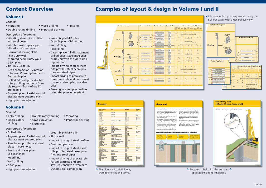
Content Overview
K 16 / �
Als Stützflüssigkeit (Stützsuspension) kommt üb-licherweise eine Suspension aus Bentonit und Was-ser zur Anwendung (Bentonitsuspension) (siehe Beschreibung in „Schlitzen“). Die Bentonitsuspension wird je nach der anstehen-den Bodenart und der verwendeten Bentonitsorte unterschiedlich aufbereitet.
Der Aushub des Schlitzes erfolgt je nach Anforde-rung in Bezug auf Tiefe, Breite und Bodenart entwe-der im Greiferverfahren oder mit einer Schlitz-wandfräse. Während des Aushubes wird die Ben-tonitsuspension ständig zugegeben, wobei darauf zu achten ist, dass sich die Schwankungen des Flüssigkeitsspiegels im Schlitz stets innerhalb der Leitwandhöhe bewegen. Bei einer Zweiphasen-schlitzwand wird die nach der Fertigstellung des
Schlitzes durch Bodenmaterial verunreinigte („ge-brauchte“) Suspension vom eingebrachten Beton verdrängt und abgepumpt. Da sie meist in diesem Zustand nicht weiterverwendet werden kann und eine Abfuhr auf Deponie aus Kosten- und Umwelt-schutzgründen zu aufwendig ist, wird sie in einer Regenerierungsanlage zur Wiederverwendung aufbereitet.
Zur Herstellung einer durchgehenden Schlitzwand werden die einzelnen Elemente erst auf Lücke fer-tiggestellt (Primärschlitz) und nach dem Erhärten dieser Lamellen die dazwischen liegenden Sekun-därschlitze ausgehoben und betoniert.
Herstellungsphasen einer Schlitzwandlamelle aus Stahlbeton (z.B. Primärschlitz)
Aushub z.B. mit Schlitzwandgreifer unter Zugabe von Stützsuspension
Einbauen der Abschalrohre
Einstellen der Bewehrung
Beton
Abschalrohr
Einbringen des Betons im Kontraktorverfahren und gleichzeitiges Abpumpen der Stützsuspension
Slurry wall
Illustrations help visualize complex applications and technologies.
Examples of layout & design in Volume I und II
Volume I
Description of methods:- Vibrating sheet pile profiles
and steel beams - Vibrated cast-in-place pile ·
Vibration of steel pipes- Horizontal sealing slabs - Thin slurry wall
(vibrated beam slurry wall) - GEWI piles- RV pile and RI pile- Deep compaction · Vibration
columns · Vibro-replacement · Geotextile pile
- Drilled pile using the double rotary drilling method · Dou-ble rotary (“front-of-wall”) drilled pile
- Augered piles · Partial and full displacement augered piles
- High-pressure injection
- Wet-mix pile/MIP pile · Dry-mix pile · CSV method
- Well drilling- Predrilling- Cast-in-place full displacement
drilled piles · Steel pipe piles produced with the vibro-drill-ing method
- Impact driving of steel sheet pile profiles, steel beam pro-files and steel pipes
- Impact driving of precast rein-forced concrete and prestressed concrete driven piles, wooden piles
- Pressing in sheet pile profiles using the pressing method
Description of methods:- Drilled pile
- Augered piles · Partial and full displacement augered piles
- Steel beam profiles and steel pipes in bore holes
- Sand- and gravel piles, Soil exchange
- Predrilling
- Well drilling
- GEWI piles
- High-pressure injection
- Wet-mix pile/MIP pile
- Slurry wall
- Impact driving of steel profiles
- Deep compaction
- Impact driving of steel sheet pile profiles, steel beam pro-files and steel pipes
- Impact driving of precast rein-forced concrete and pre-stressed concrete driven piles
- Dynamic soil compaction
General:
• Kelly drilling • Double rotary drilling • Vibrating
• Single rotary • Grab excavation • Impact pile driving
drilling • Slurry wall
Volume II
13/10/08
SteelPressing15Z and
U profiles– Z and
U profilesZ and
U profiles–
depending on the type of profile down to a depth of max. 15 m
12–15
R
R
* Where a ring vibrator is used (with suitably designed leader top), the steel pipe may extend beyond the length of the leader
Sheet pile profiles
Combined profiles
Wood
Concrete
Steel
P
P
P
P
Q
Q
Impact pile driving
Hydraulic hammerH 85
Sheet pile press 4080 or 4125
22
22
22
22
all
HEB 600
–
450x450
–
–
610
–
all
HEB 600
–
450x450
–
–
depending on the type of profile down to a depth of max. 22 m
508
–
standard down to a depth of 15 m
18
16
18
18
all
HEB 400
–
450x450
–
–
508
–
20
20
22
20
Sheet pile profiles
Steel beam profiles
Combined profiles
Steel pipes
Driven wood pile
Precast reinf. concrete driven pile
K
H
H
L
L
N
M
Suspension
Lime/Cement
Concrete
E
I
I
L
Double rotary drive DBA 200
Casing with auger
Double rotary drilling
610
610
appr. 600
appr. 500
down to a depth of max. 24 m
down to a depth of max. 24 m
appr. 600
appr. 600
possible with LRB 155, but not standard
610
appr. 600
750
750
appr. 750
appr. 600
appr. 750
appr. 750
900
appr. 750
12
12
18
18
18
18
10
18
–
–
–
–
–
–
–
–
–
–
–
–
–
–
–
–
17
17
18
15
18
18
12
18
–
–
–
–
–
–
–
–
508
508
appr. 500
appr. 400
appr. 500
appr. 500
508
appr. 500
17
17
20
18
20
20
12
20
High pressure injection
Drilled pile
FOW (“front-of-wall“) drilled pile
CSV method
Dry-mix pile
Predrilling
Well drilling
GEWI pile
Augered pile
Partial and full displacement pile
Wet-mix pile/MIP pile
Steel
Concrete
Suspension
Steel and Suspension
Gravel/Sand
B
A
A
B
E
F
G
A
C
D
G
G
Method and equipment
Vibrating
Product/application Described underInstallation material
Top vibrator 23 VML
Ring vibrator20 VMR
LRB 155 Soil conditions and dimensions (guidelines)Soil types light medium heavy
24
24
24*
24*
21
21*
21*
all
HEB 600
–
–
I 800
–
–
–
–
610
610
–
610
610
Depth max
m
Profiles/ dimensions
mm
Ø max
mm
all
HEB 600
–
–
I 600
–
–
–
–
depending on the type of profile down to a depth of max. 24 m
508
508
down to a depth of max. 24 m
–
down to a depth of max. 24 m
depending on the type of profile down to a depth of max. 24 m
depending on the installation method down to a depth of max. 24 m*
508
508
Depth max
m
Profiles/ dimensions
mm
Ø max
mm
16
16
18*
18*
15
18*
18*
all
HEB 400
–
–
I 600
–
–
–
–
508
508
–
508
508
Depth max
m
Profiles/ dimensions
mm
Ø max
mm
20
20
24*
24*
21
21*
21*
Steel pipes
Sheet pile profiles
Steel beam profiles
Vibrated cast-in-place pile
GEWI pile
RI and RV pile
Deep compaction
Combined profiles
Horizontal sealing slabs
Thin slurry wall
Vibro-repl. columns/vibro-repl.
Geotextile pile
© 53007 BVV Spezialtiefbautechnik/kom DESIGN·1 GmbH Munich
Comp_LRB155_EN_1_Ed.qxd 28.08.2006 11:03 Uhr Seite 2
It is easy to find your way around using the pull-out pages with a general overview.
SteelPressing15Z and
U profiles– Z and
U profilesZ and
U profiles–
depending on the type of profile down to a depth of max. 15 m
12–15
R
R
* Where a ring vibrator is used (with suitably designed leader top), the steel pipe may extend beyond the length of the leader
Sheet pile profiles
Combined profiles
Wood
Concrete
Steel
P
P
P
P
Q
Q
Impact pile driving
Hydraulic hammerH 85
Sheet pile press 4080 or 4125
22
22
22
22
all
HEB 600
–
450x450
–
–
610
–
all
HEB 600
–
450x450
–
–
depending on the type of profile down to a depth of max. 22 m
508
–
standard down to a depth of 15 m
18
16
18
18
all
HEB 400
–
450x450
–
–
508
–
20
20
22
20
Sheet pile profiles
Steel beam profiles
Combined profiles
Steel pipes
Driven wood pile
Precast reinf. concrete driven pile
K
H
H
L
L
N
M
Suspension
Lime/Cement
Concrete
E
I
I
L
Double rotary drive DBA 200
Casing with auger
Double rotary drilling
610
610
appr. 600
appr. 500
down to a depth of max. 24 m
down to a depth of max. 24 m
appr. 600
appr. 600
possible with LRB 155, but not standard
610
appr. 600
750
750
appr. 750
appr. 600
appr. 750
appr. 750
900
appr. 750
12
12
18
18
18
18
10
18
–
–
–
–
–
–
–
–
–
–
–
–
–
–
–
–
17
17
18
15
18
18
12
18
–
–
–
–
–
–
–
–
508
508
appr. 500
appr. 400
appr. 500
appr. 500
508
appr. 500
17
17
20
18
20
20
12
20
High pressure injection
Drilled pile
FOW (“front-of-wall“) drilled pile
CSV method
Dry-mix pile
Predrilling
Well drilling
GEWI pile
Augered pile
Partial and full displacement pile
Wet-mix pile/MIP pile
Steel
Concrete
Suspension
Steel and Suspension
Gravel/Sand
B
A
A
B
E
F
G
A
C
D
G
G
Method and equipment
Vibrating
Product/application Described underInstallation material
Top vibrator 23 VML
Ring vibrator20 VMR
LRB 155 Soil conditions and dimensions (guidelines)Soil types light medium heavy
24
24
24*
24*
21
21*
21*
all
HEB 600
–
–
I 800
–
–
–
–
610
610
–
610
610
Depth max
m
Profiles/ dimensions
mm
Ø max
mm
all
HEB 600
–
–
I 600
–
–
–
–
depending on the type of profile down to a depth of max. 24 m
508
508
down to a depth of max. 24 m
–
down to a depth of max. 24 m
depending on the type of profile down to a depth of max. 24 m
depending on the installation method down to a depth of max. 24 m*
508
508
Depth max
m
Profiles/ dimensions
mm
Ø max
mm
16
16
18*
18*
15
18*
18*
all
HEB 400
–
–
I 600
–
–
–
–
508
508
–
508
508
Depth max
m
Profiles/ dimensions
mm
Ø max
mm
20
20
24*
24*
21
21*
21*
Steel pipes
Sheet pile profiles
Steel beam profiles
Vibrated cast-in-place pile
GEWI pile
RI and RV pile
Deep compaction
Combined profiles
Horizontal sealing slabs
Thin slurry wall
Vibro-repl. columns/vibro-repl.
Geotextile pile
© 53007 BVV Spezialtiefbautechnik/kom DESIGN·1 GmbH Munich
Comp_LRB155_EN_1_Ed.qxd 28.08.2006 11:03 Uhr Seite 2
Glossary
© 53007 BVV Spezialtiefbautechnik/kom DESIGN·1 GmbH Munich
Glossary 3
Drilled beam Drilled pile Drilling HDrilled pile Drilling HDrilled well Well drilling Drilling MDrilling drive Drilling DrillingDrilling rod Drilled pile Drilling HDrive cap Impact driving Impact drivingDrive pipe Impact driving Impact drivingDriven pile Impact driving P, QDriven steel pile Steel beam profiles, steel pipes Impact driving PDry-mix pile Drilling LDuctile cast iron pile Steel pipes Impact driving PDuctile driven pile Ductile pile Impact driving PDuctile iron pile Steel pipes Impact driving PDuctile pile Steel pipes Impact driving P
E Exciter Vibrator Vibrating VibratingExternal impacting process Steel pipes Impact driving P
F Foot grouting Sheet pile wall profile Vibrating, impact driving A, PFOW (front-of-wall) drilling FOW (front-of-wall) drilled pile Drilling HFOW (front-of-wall) pile Drilled pile Drilling HFree-fall hammer Hammer Impact driving Impact drivingFrequency Vibrator Vibrating VibratingFull displacement cast-in-place drilled pile Vibro-drilling OFull displacement drilled pile Full displacement cast-in-place pile Vibro-drilling OFull displacement pile Displacement pile Vibrating, drilling B, I
G Geotextile hose Geotextile stocking, geotextile pile Vibrating GGeotextile pile Vibrating GGeotextile sand pile Geotextile pile Vibrating GGeotextile stocking Geotextile hose, geotextile pile Vibrating GGEWI pile Vibrating, drilling EGravel column Gravel pile, vibro-replacement column Vibrating GGravel drain pile Gravel pile, vibration columns Vibrating GGravel pile Vibration columns Vibrating GGravel pile with textile skin Geotextile pile Vibrating GGroundwater well Well drilling Drilling MGrout Thin slurry wall Vibrating D
H Hammer Impact driving Impact drivingHammer guide Impact driving Impact drivingHigh pressure injection Drilling KHigh-frequency vibrator Vibrator Vibrating VibratingHigh-pressure soil stabilisation/ High-pressure injection Drilling KcementationHollow stem Augered pile Drilling IHollow stem auger Augered pile Drilling IHorizontal sealing slab Vibrating CHP pile Steel beam profiles Vibrating, impact driving A, PHydraulic free-fall hammer Hammer Impact driving Impact drivingHydraulic hammer Hammer Impact driving Impact drivingHZ pile Steel beam profiles Vibrating, impact driving A, PHZ wall Combined wall Vibrating, impact driving A, P
Term / Product / See Operation DescribedApplication under
Glossary_Kompendium_EN_H02.qxd 28.08.2006 10:39 Uhr Seite 3
The glossary lists definitions, cross-references and terms.
Thin slurry wall (vibrated beam slurry wall)
© 53007 BVV Spezialtiefbautechnik/kom DESIGN·1 GmbH Munich
D 12 / 3
Creating a thin slurry wall by the vibration process
D_Thin_slurry_walls_EN_H03.qxd 29.08.2006 18:08 Uhr Seite 3
Thin slurry wall (vibrated beam slurry wall)
© 53007 BVV Spezialtiefbautechnik/kom DESIGN·1 GmbH Munich
D 12 / 3
Creating a thin slurry wall by the vibration process
D_Thin_slurry_walls_EN_H03.qxd 29.08.2006 18:08 Uhr Seite 3
Thin slurry wall (vibrated beam slurry wall)
© 53007 BVV Spezialtiefbautechnik/kom DESIGN·1 GmbH Munich
D 12 / 3
Creating a thin slurry wall by the vibration process
D_Thin_slurry_walls_EN_H03.qxd 29.08.2006 18:08 Uhr Seite 3


