

Computational Evaluation of Inlet Distortion on an Ejector Powered Hybrid Wing Body at Takeoff and Landing Conditions
Daniel M. Tompkins, Matthew R. Sexton, Edward A. Mugica, Michael D. BeyarBoeing Research & Technology, Huntington Beach, CA, 92647
Michael J. Schuh, Paul M. StremelNASA Ames Research Center, Moffett Field, CA, 94035
Karen A. Deere, Naomi McMillin, Melissa B. CarterNASA Langley Research Center, Hampton, VA, 23681
AIAA SciTech 2016, Jan 4-8 2016, San Diego, CA1
https://ntrs.nasa.gov/search.jsp?R=20160000932 2020-07-07T05:24:14+00:00Z
Engineering, Operations & TechnologyBoeing Research & Technology
Computational Evaluation of Inlet Distortion on an Ejector Powered Hybrid Wing Body at Takeoff and Landing Conditions
Daniel M. Tompkins, Matthew R. Sexton, Edward A. Mugica, Michael D. BeyarBoeing Research & Technology, Huntington Beach, CA, 92647
Michael J. Schuh, Paul M. StremelNASA Ames Research Center, Moffett Field, CA, 94035
Karen A. Deere, Naomi McMillin, Melissa B. CarterNASA Langley Research Center, Hampton, VA, 23681
ABPSI-01/GEPC-01, NASA ERA Systems Integration, Jan 4th, 2016 SCITECH 2016, San Diego, CA
2
Boeing Research & Technology | Flight & Vehicle Technology
Introduction§ Due to the aft, upper surface engine location on the Hybrid Wing
Body (HWB) planform, there is potential to shed vorticity and separated wakes into the engine when the vehicle is operated at off-design conditions and corners of the envelope required for engine and airplane certification
§ CFD simulations were performed of the full-scale reference propulsion system, operating at a range of inlet flow rates, flight speeds, altitudes, angles of attack, and angles of sideslip to identify the conditions which produce the largest distortion and lowest pressure recovery
§ Pretest CFD was performed by NASA and Boeing, using multiple CFD codes§ Model integration § Characterize inlet flow distortion patterns§ Help define the wind tunnel test matrix
§ CFD was also performed post-test; when compared with test data, it was possible to make comparisons between measured model-scale and predicted full-scale distortion levels.
3
Boeing Research & Technology | Flight & Vehicle Technology
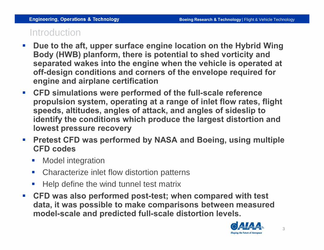
Pre-Test CFD for Model Integration: Ejector Sizing
CFD Analysis was used to size the constant-area duct in the ejector▪ CFD results plot the difference in Cp with the
ejector present and absent▪ A longer constant-area duct in the ejector
minimizes the ejectors’ effect on pressure distributions on the body
4
Boeing Research & Technology | Flight & Vehicle Technology
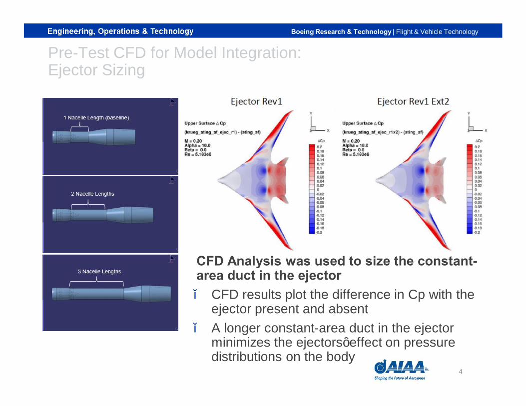
Pre-Test CFD for Model Integration: Influence of Support Stand
▪ Ejector support had negligible effects on the flowfield through the ejector assembly
▪ Top surface of the wing appeared unaffected by the ejector support
▪ Ejector support primarily influenced the underside of the wing body
Bottom View Top View Ejector Flowfield
Model Support
Ejector Assembly
Ejector Support
5
Boeing Research & Technology | Flight & Vehicle Technology
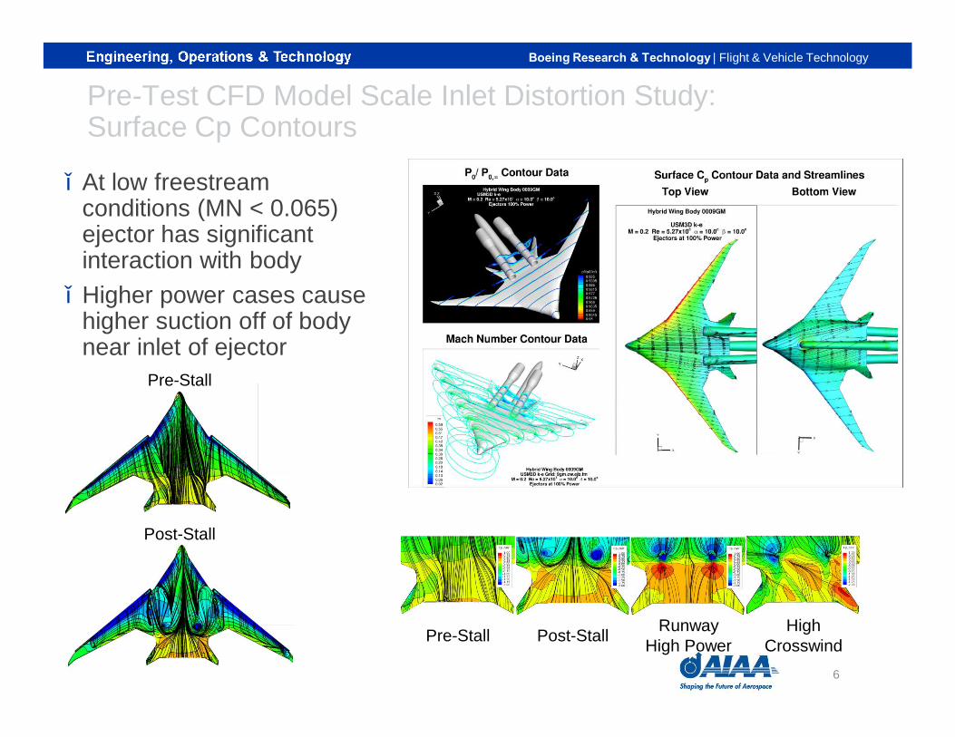
Pre-Test CFD Model Scale Inlet Distortion Study:Surface Cp Contours
▪ At low freestreamconditions (MN < 0.065) ejector has significant interaction with body
▪ Higher power cases cause higher suction off of body near inlet of ejector
Pre-Stall
Post-Stall
Pre-Stall Post-Stall RunwayHigh Power
HighCrosswind
6
Boeing Research & Technology | Flight & Vehicle Technology
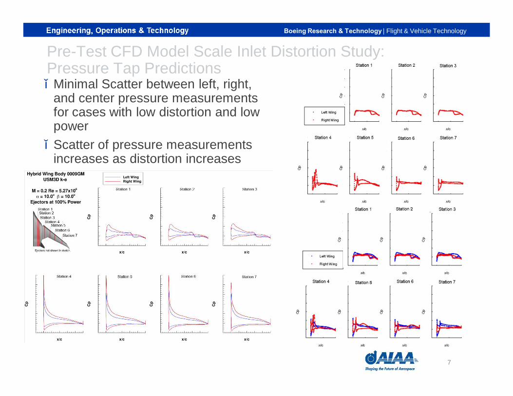
Pre-Test CFD Model Scale Inlet Distortion Study:Pressure Tap Predictions▪ Minimal Scatter between left, right,
and center pressure measurements for cases with low distortion and low power
▪ Scatter of pressure measurements increases as distortion increases
7

Boeing Research & Technology | Flight & Vehicle Technology
Pre-Test CFD Model Scale Inlet Distortion Study:Total Pressure Recovery Contours
▪ “Ground” vortex off of HWB body is ingested at MN 0.05
▪ At high β, significant distortion is seen
▪ Wing vortex shedding at moderate αdoes not appear to interact with inlets
Low β, MN 0.05
Moderate β, MN 0.10
High β, MN 0.06458

Boeing Research & Technology | Flight & Vehicle Technology
Pre-Test CFD Model Scale Inlet Distortion Study:Nacelle Placement Study Slight preference for moving inlet▪ Up▪ Aft, or ▪ Up, aft, and inboard together
9
Boeing Research & Technology | Flight & Vehicle Technology
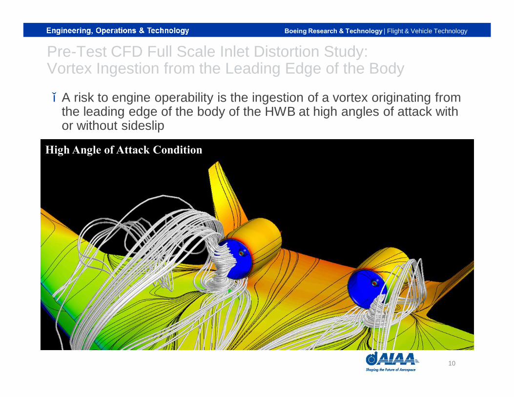
Pre-Test CFD Full Scale Inlet Distortion Study:Vortex Ingestion from the Leading Edge of the Body
▪ A risk to engine operability is the ingestion of a vortex originating from the leading edge of the body of the HWB at high angles of attack with or without sideslip
High Angle of Attack Condition
10
Boeing Research & Technology | Flight & Vehicle Technology
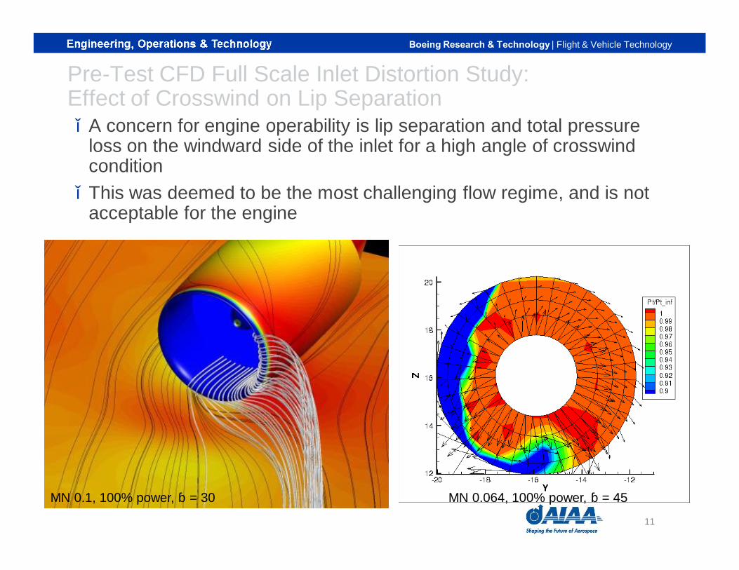
Pre-Test CFD Full Scale Inlet Distortion Study:Effect of Crosswind on Lip Separation▪ A concern for engine operability is lip separation and total pressure
loss on the windward side of the inlet for a high angle of crosswind condition
▪ This was deemed to be the most challenging flow regime, and is not acceptable for the engine
MN 0.1, 100% power, β = 30 MN 0.064, 100% power, β = 45
11
Boeing Research & Technology | Flight & Vehicle Technology
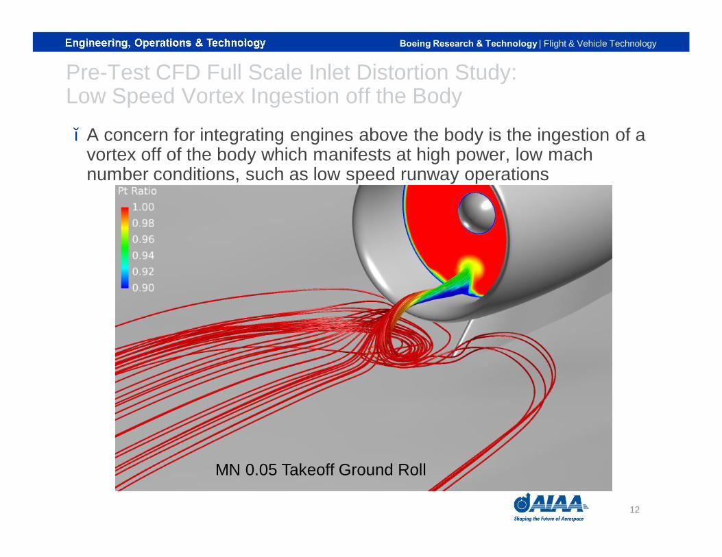
Pre-Test CFD Full Scale Inlet Distortion Study:Low Speed Vortex Ingestion off the Body
▪ A concern for integrating engines above the body is the ingestion of a vortex off of the body which manifests at high power, low machnumber conditions, such as low speed runway operations
MN 0.05 Takeoff Ground Roll
12
Boeing Research & Technology | Flight & Vehicle Technology
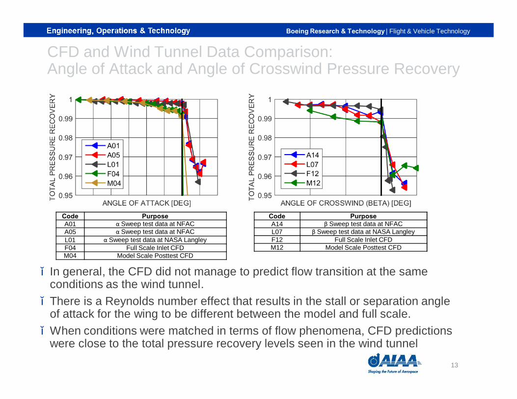
CFD and Wind Tunnel Data Comparison:Angle of Attack and Angle of Crosswind Pressure Recovery
Code PurposeA01 α Sweep test data at NFACA05 α Sweep test data at NFACL01 α Sweep test data at NASA LangleyF04 Full Scale Inlet CFDM04 Model Scale Posttest CFD
Code PurposeA14 β Sweep test data at NFACL07 β Sweep test data at NASA LangleyF12 Full Scale Inlet CFDM12 Model Scale Posttest CFD
▪ In general, the CFD did not manage to predict flow transition at the same conditions as the wind tunnel.
▪ There is a Reynolds number effect that results in the stall or separation angle of attack for the wing to be different between the model and full scale.
▪ When conditions were matched in terms of flow phenomena, CFD predictions were close to the total pressure recovery levels seen in the wind tunnel
13

Boeing Research & Technology | Flight & Vehicle Technology
CFD and Wind Tunnel Data Comparison:Post-Test CFD Model Scale Inlet Distortion Study
CONDITION CFD RESULTS
Mach 0.20 Moderate Angle of
Attack Case
Mach 0.20 High Angle of Attack
Case
Mach 0.05 High Power Case
CONDITION WIND TUNNEL TEST RESULTS
Mach 0.20 Moderate Angle of
Attack Case
Mach 0.20 High Angle of Attack
Case
Mach 0.05 High Power Case
▪ Qualitative agreement in terms of total pressure levels between experiment and CFD
▪ The level of distortion seen in the wind tunnel tests near wing stall or high sideslip conditions were within the level of distortion provided to Pratt & Whitney for the PSC inlet fan compatibility assessment
▪ A further discussion of the comparison between CFD and wind tunnel test results is in Ref. 1
14
Boeing Research & Technology | Flight & Vehicle Technology
Conclusions§ CFD of the full-scale reference inlet was performed to predict
inlet distortion levels and provide data for engine company operability assessment
§ Pretest CFD was also run in a collaborative effort between Boeing and NASA to characterize inlet flow distortion and provide insight for test planning
§ Boeing and NASA also performed CFD to help determine the size and layout of ejector hardware
§ The model-scale ejector hardware was designed and built to measure inlet distortion levels via the ejector campaign
§ Subsequent to collecting data, CFD was run on the post-test model-scale ejector
§ Therefore, it was possible to make comparisons between experimental data and CFD to make projections of distortion levels for the full-scale configuration
15
Boeing Research & Technology | Flight & Vehicle Technology
References1) Carter, Melissa B. et al., “Experimental Evaluation of Inlet
Distortion on an Ejector Powered Hybrid Wing Body at Take-off and Landing Conditions,” AIAA Science and Technology Forum and Exposition 2016. (submitted for publication)
16

17


